Embed Size (px)
Citation preview
EXPERIMENTAL ANALYSIS OF PKW HYDRAULIC PERFORMANCE AND
GEOMETRIC PARAMETERS OPTIMUM
Machiels O.1, 2
, Erpicum S.1, Pirotton M.
1, Dewals B.
1 and Archambeau P.
1
1HECE, ArGEnCo department, University of Liège, Chemin des chevreuils 1 B52/3, 4000
Liège, Belgium, Email: [email protected], Tel: +32 (0)4 366 95 60, Fax: +32 (0)4 366 95
58
2Belgian Fund for education to Industrial and Agricultural Research - FRIA
Abstract
In the scope of dam rehabilitation to manage floods increase or to increase water storage, the
Piano Key Weir is a good solution for concrete dams. The efficiency of Piano Key Weirs is
now well demonstrated through various experimental studies. Even if parametrical studies are
currently undertaken, the definition of the optimal shape to give to the structure is still
missing due to the lack of knowledge in the influence of the large set of geometrical
parameters. This paper presents the results of a combine experimental and numerical study of
PKW. On the one hand, the study, led on a large scale model of PKW, aims at defining the
main parameters influencing the hydraulic behaviour of the structure. On the other hand, the
influence of these main parameters has been studied on several scale models considering
variation of the weir height, the keys widths and the overhangs lengths. The results of the
experiments enable to define optimal values for a common variation of these parameters.
Keywords: Spillway, Piano Key Weir, Experimental, Rehabilitation

Introduction
The Piano Key Weir (PKW) is a particular form of labyrinth weir, developed by
Lempérière (Blanc and Lempérière 2001, Lempérière and Ouamane 2003), using up- and/or
downstream overhangs to limit its basis length and enabling its use directly on dam crest. The
PKW is thus a cost effective solution for dam rehabilitation but also for new dam projects
with low space or limited reservoir segment available to release a large design discharge. The
first scale model studies showed that this new type of weir can be four times more efficient
than a traditional ogee-crested weir at constant head and crest length on the dam (Ouamane
and Lempérière 2006a).
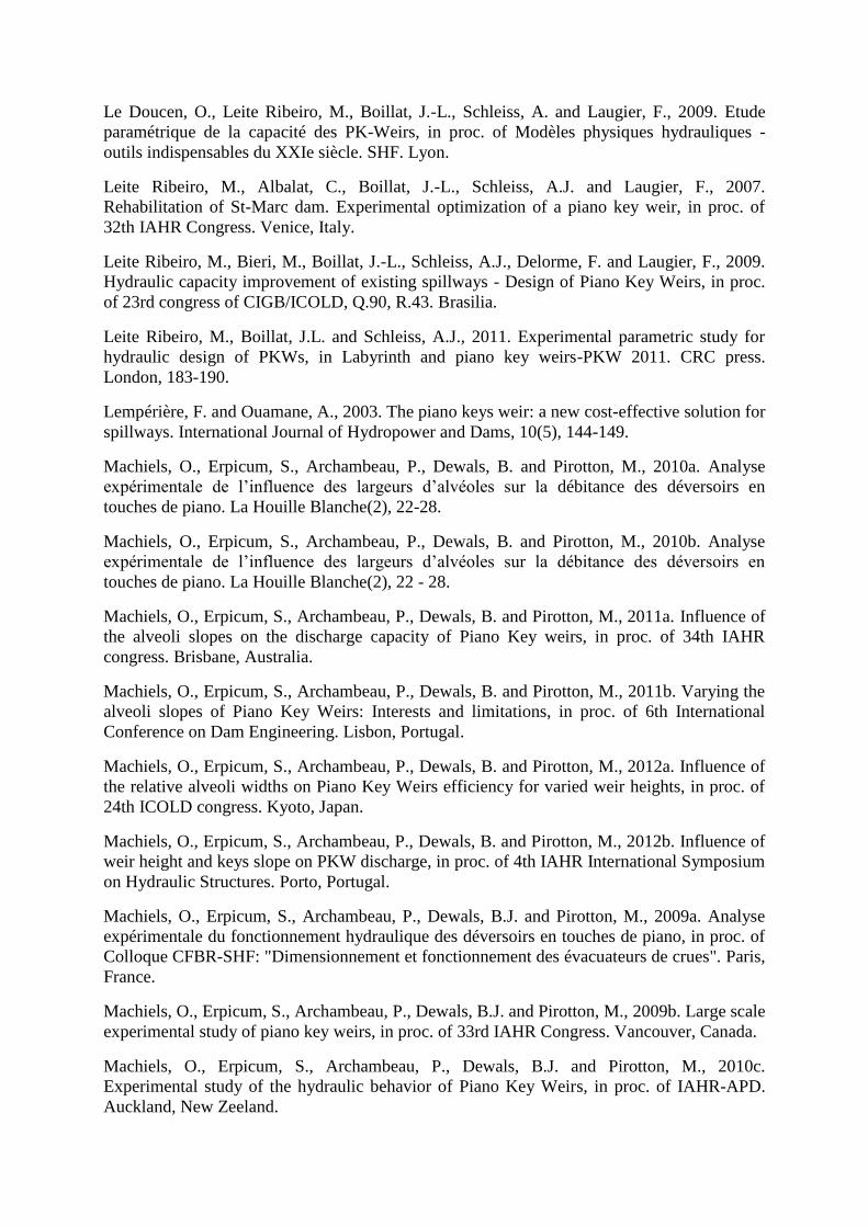
The geometric specificities of the PKW, such as up- and/or downstream overhangs with
variable width, inlet and outlet bottom slopes, involve a large set of parameters increasing the
difficulty of a systematic optimization. Following Pralong et al. (2011), the “PKW-unit” can
be defined as the basic structure of a PKW, composed of two transversal walls, an inlet and
two half-outlet keys. The main geometric parameters of a PKW are the weir height P, the unit
width Wu, the number of PKW-units Nu, the lateral crest length B, the inlet and the outlet
widths Wi and Wo, the up- and downstream overhang lengths Bo and Bi, and the wall thickness
Ts (Figure 1). The i, o and s indexes are used respectively for the inlet, the outlet key and the
side wall characteristics.
Even if the first prototype size PKW have been built by “Electricité de France (EDF)” in
France since 2006 (Laugier 2007, Bieri et al. 2009, Laugier et al. 2009, Leite Ribeiro et al.
2009, Vermeulen et al. 2011), the definition of the optimal geometry of the structure has been
still poorly approached. Until now, even if first systematic pre-design method has been
developed to limit the iterations on scale models (Machiels et al. 2011d), the hydraulic design
of a PKW is mainly performed on the basis of experimental knowledge and scale model
studies, modifying step by step an initial geometry following the ideas of the project
engineers (Leite Ribeiro et al. 2007, Cicero et al. 2010).
The first parametrical studies, carried out to characterize the influence of a number of the
geometrical parameters, showed the interests of increasing the inlet/outlet widths
ratio (Ouamane and Lempérière 2006a, Le Doucen et al. 2009, Machiels et al. 2010a,
Anderson 2011), the upstream overhang length (Ouamane and Lempérière 2006a, b,
Anderson 2011) and the weir height (Ouamane and Lempérière 2006a, b, Le Doucen et al.
2009, Machiels et al. 2011c), to increase the release capacity of the PKW. A profiling of the
shape of the upstream overhang also contributes to increase the discharge capacity (Ouamane
and Lempérière 2006a, b, Anderson 2011). Some studies finally demonstrated the interest of
the PKW in terms of aeration capacity and floating debris response (Ouamane and Lempérière
2006a, b). Through all these parametrical studies, only two optimization curves have been
proposed, concerning the influence of the inlet/outlet widths ratio for PKW with only
upstream overhangs (Machiels et al. 2010a) and the influence of the weir height (Machiels et
al. 2011c).
In order to improve the understanding of the flow over a PKW, a physical approach has been
initiated at the University of Liege (Machiels et al. 2011e). The results obtained on a large
scale model, so enables to highlight the mainly influent geometrical parameters on the PKW
flow behaviour. Following these observations, several parametric models have been studied.
The results of this study, presented in this paper, enable the optimisation of the weir height,
the inlet/outlet widths ratio and the upstream/downstream overhangs lengths ratio in terms of
release capacity.

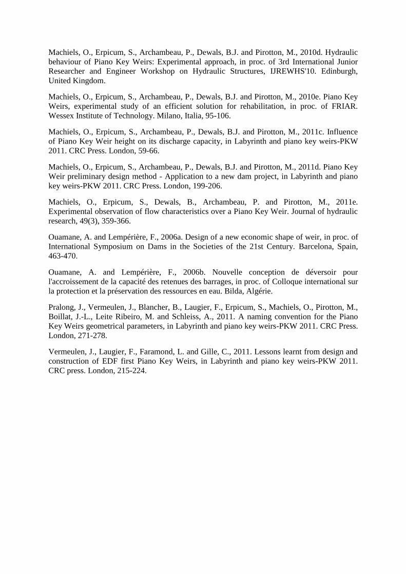
Experimental set-up
A specific experimental facility has been built to perform all the scale model tests depicted
hereafter. The channel, 7.2 m long, 1.2 m wide and 1.2 m high is fed up by two pumps
delivering up to 300 l/s in an upstream stilling basin (Figure 2). The upstream entry of the
channel is equipped with a metal grid and a synthetic membrane ensuring uniform
alimentation conditions. Two Plexiglas plates on both channel sides allow to observe the flow
patterns on the whole channel height at the location of the PKW model. Specific convergent
structures allow reducing the channel width to the variable width of the tested models.
Downstream of the tested models optional dividing walls allow the separation of the flows
coming from the different keys. These dividing channels are closed downstream by triangular
sharp-crested weirs for which the stage-discharge curve was previously established.
During the study, 36 models of PKW (a large scale model and 35 parametric models) have
been tested. All PKWs have been made in PVC to minimize the effects of friction. The
various thicknesses of the PVC plates have been chosen in agreement with the structural
considerations of concrete prototypes. All models have been placed on a 0.2 m high support
representing the dam crest use of the structure.
During the various experimental tests, discharges, water free surface levels, stream lines
positions, flow velocities and pressures have been measured. The upstream discharges have
been measured using an electromagnetic flowmeter with a precision of ± 1 l/s. The free
surface level measurements have been performed using electronic limnimeters with a
precision of ± 0.5 mm. Pitot tubes (Klopfenstein Jr 1998) have been placed on the channel
cross section to measure the flow velocity and the pressure at different heights and at different
points upstream the weir and along the inlet key. The accuracy of these measurements is ± 1
mm. That corresponds to a precision of ± 0.15 m/s on velocity.
Large scale model
In order to enhance the understanding of the physics of the flows on a PKW, a 1:10 scale
model of a basic PKW geometry (Wi/Wo = 1, Bi/Bo = 1, L/W = 4.15, Pi/Wu = 1.31, Pi/Po = 1)
has firstly been exploited in a wide range of discharges (Machiels et al. 2009b, Machiels et al.
2010c, e, d, Machiels et al. 2011e). The model has been used to investigate flow types on the
weir crests and to characterize these flow types in terms of discharge, velocity, pressure and
flow patterns. To achieve this goal, 1.5 inlets and 1.5 outlets have been modelled. The halves
outlet and inlet, along the Plexiglas walls, allow the observation of the flow. The full ones, at
the centre of the channel, enable measurements without side effects.
According to the flow observations and to the measurements of the free surface, the velocity
and the pressure profiles, the typical curve of the discharge coefficient CdW of the PKW
function of the ratio between upstream water head H and weir height P (Figure 3) can be
explained.
For low heads H, the transition from a partially clinging nappe to a leaping nappe and then to
a springing nappe (Johnson 2000) can be observed on the different parts of the PKW crest.
These transitions occur for different heads depending on the crest thickness T and shape.
Using 2 cm thick PVC plates, the side crest thickness is 2 cm, while the upstream and
downstream crests thickness are 2.4 cm because of the slope of the plates.
On the side crests, for the smallest head ratio (H/P = 0.05), the leaping nappe remains in
contact with the crest. For H/Ts ratios between 2.35 and 2.6, the nappe becomes springing and
is detached from the crest on the most downstream 3/4 of the crest length. This situation
persists for higher water heads. The same behaviour is observed on the downstream crest of
the inlet key. The transition from a leaping to a springing nappe is observed for H/Ti ratios
between 2.4 and 2.6. The flow behaviour on the upstream crest is different. Indeed, for the
lowest head ratios, the nappe is completely attached to the walls. Then for H/To ratios
between 3.48 and 3.64, the nappe is directly fully aerated.
For very low heads (H/P < 0.06), surface tension effects unable concluding on the discharge
capacity of the model. Until the transition from a leaping nappe to a springing one along the
side crest, the discharge coefficient increases with the head as the crest efficiency increases.
For head ratios H/P over 0.1, a springing nappe appears on the 3/4 of the side crest length, the
discharge coefficient stabilizes with increasing heads. That can be explained by the combined
effects of the decrease of the side crest efficiency, due to its orientation perpendicular to the
main flow direction, and the increase of efficiency, due to the leaping nappe on the
downstream crest and the clinging nappe on the upstream crest. When the downstream nappe
becomes springing, the discharge coefficient begins to decrease continuously with increasing
heads because of a less important increase of efficiency only due to clinging nappe on the
upstream crest. Finally, the discharge coefficient decreases more importantly when the
upstream nappe becomes free for H/P over 0.2.
The continuous decrease in efficiency, observed then in Figure 3, can be explained by the
analysis of the streamlines distribution and Froude profiles for high heads. For these heads,
the downstream crest of the inlet key is over supplied because of the flow inertia in the
downstream direction. More streamlines than for low heads reach this section of the PKW.
The side crest is poorly supplied because of the same longitudinal flow inertia. The
streamlines along this crest are less dense. The upstream crest of the outlet key is supplied
equally for high heads and for low heads (same streamlines).
According to the Froude calculation, enabled as the pressure measurements show hydrostatic
profiles all over the weir, a control section (Fr = 1) appears where the velocities become too
important. This control section moves upstream with the rising head, where the water height
is more important. The efficient length of the weir, and thus the global discharge coefficient
of the PKW, decreases more and more importantly. Finally, for higher heads the control
section should be located directly at the entrance of the inlet key. The discharge capacity
decreases less importantly and seems to tend to a limit value.
These observations enable to explain the interest of increasing the inlet width (Ouamane and
Lempérière 2006a, Machiels et al. 2009a), slope or height (using crest extension by
example) (Ouamane and Lempérière 2006a, b) to increase the inlet cross section. This would
limit the occurrence of control section, thus improving the discharge capacity of the weir. It
also explains the hydraulic interest of using only upstream overhangs (Ouamane and
Lempérière 2006a), which reduce the inlet key length and increase its slope, so the influence
of the control section is limited. Finally, the use of a non-rectangular shape of the front part of
the upstream overhangs (Ouamane and Lempérière 2006b) decreases the recirculation zone
size and therefore increases the discharge capacity.
Parametric models
In a second time, the study aims to allow determining the influence of the different
geometrical parameters of the PKW on its discharge capacity. To achieve this goal, several
scale models with variable geometries have been tested. Considering the results and the
observations from the 1:10 scale model study, four main geometrical parameters can be
distinguished from the large set of parameters induced by the complex geometry of PKW: the
crest length, the weir height, the keys width and the overhangs length.
The crest length seems to be the main parameter for PKW. Indeed, it defines the relative
length L/W and so the maximal efficiency of the weir for low heads. As this parameter has
already been extensively studied (Ouamane and Lempérière 2006a, Le Doucen et al. 2009,
Leite Ribeiro et al. 2011) and as its main influence is, as expected, only to increase the
effective weir length, this parameter has not been studied in the present parametrical study.
PKW height
On the 1:10 scale model, the flow contraction at the inlet key entrance and the apparition of a
control section in the downstream part of the key have been identified as the two main reasons
of the observed efficiency decrease with increasing heads. As the increase of the weir height
decreases the flow velocities along the inlet key, it must increase significantly the PKW
efficiency.
To test the influence of PKW height, in a first time, 7 PKW models with varying height
(Pi/Wu = 0.33, 0.5, 0.67, 0.8, 1, 1.33, 2), providing varied bottom slopes of the inlet and outlet
keys, have been studied (Machiels et al. 2011a, b, Machiels et al. 2011c). The inlet/outlet
widths ratio Wi/Wo of all models is 1.5, the ratio between the total length of the crest L and the
width of the weir W is 5, and the two overhangs are symmetric and equal to the third of the
side crest length B. In a second time, to highlight the relative influence of parapet walls and of
other geometric parameters of PKW, several models have been tested with and without
parapet walls, providing variants characterized by either the same bottom slopes or by the
same total height, while varying values have been used for inlet/outlet widths ratio, developed
length ratio and slopes of the keys. 6 models have been studied, providing 14 variants of
PKW (Machiels et al. 2012b).
According to the experimental results, the optimal slope, in terms of discharge capacity, is
between 1.1 and 1.2, for the tested values of the steady non-dimensional ratios (L/W = 5,
Wi/Wo = 1.5, Bo/Bi =1, Bo/B = 0.33) (Figure 4). However, 95% of the maximum discharge
capacity is already provided with slopes between 0.4 and 0.8 depending on the upstream head.
Even if the hydraulic criterion encourages increasing the bottom slope of the PKW,
modification of the geometry involves technical and economic aspects that designers have to
deal with. So the optimization of the structure may change function of the large set of design
criteria varying with the project constraints. By example, assuming the global cost of a PKW
building is directly proportional with the volume of the structure, the optimal geometry,
considering economic interests, is the one which assures, for a given head, the highest
discharge release q per cubic meter of concrete Vconcrete necessary to build a PKW-unit. In this
case the optimal geometry varies with the design head between Si = 0.3 to 0.35 (Figure 4).
The results obtained from the 14 variants of PKW, with or without parapet walls, highlight
the main importance of the weir height, instead of keys slopes. When the vertical aspect ratio
P/Wu decreases from is optimal value of 1.5, the efficiency of the weir decreases quickly
(until 30% for P/Wu decreasing from 1.33 to 0.5). The keys slopes are of minor importance,
only allowing a few percentage of discharge increase. Higher outlet key slope will be
preferred, for low height geometries, as they increase the resilience capacity of the outlet key.
For sufficiently high weir geometries, the definition of the optimal keys slopes must be
balanced between the low gain in efficiency obtained with parapet walls decreasing the inlet
key slope, and the increase of the cost resulting of the complexity of the structure using
parapet walls. Furthermore, the height of the parapet wall has to be limited to keep the interest
of upstream overhang use, which limit the flow velocity at the inlet key entrance and so give
to the PKW a better discharge capacity than a labyrinth weir with same horizontal shape.

As practical design of PKW is based on project constraints which most of the time impose the
weir height (normal reservoir level, structural characteristics of the dam, …), it is more
convenient and cost effective to use standard PKW, without parapet walls. However, parapet
walls provide a good opportunity for future PKW rehabilitations, enabling in some cases to
increase the discharge of the initial PKW by up to 20% by a limited increase of the maximal
reservoir level. Parapet walls must thus be conserved and studied as safety works for future.
Keys widths
As the increase of the inlet key width decreases the flow velocities along the inlet key, it also
must increase significantly the PKW efficiency. However, the increase of the inlet width, for
given weir width and crest length, induces a decrease of the outlet width. A too narrow outlet
key may be unable to evacuate the outlet flow under supercritical conditions and may so
decrease the global weir efficiency. An optimal value of the Wi/Wo ratio must thus be found
between inlet width increase and outlet resilience capacity.
As the results presented here before have shown various optimal PKW heights regarding pure
hydraulic or technico-economic considerations, the influence of the keys widths has been
studied considering two PKW heights (P/Wu = 1.33; 0.5) corresponding respectively to these
two optimum. For each weir height, seven models of PKW, with varied ratio between inlet
and outlet keys widths (Wi/Wo = 0.5; 0.667; 0.796; 1; 1.256; 1.5; 2), have been
tested (Machiels et al. 2012a). The ratio between the total length of the crest and the width of
all weirs is 5, and the two overhangs are symmetric (type A PKW) with a length equals to the
third of the whole side crest length. Before these tests, the influence of the Wi/Wo ratio had
been studied on PKW models with only upstream overhangs (type B PKW) (Machiels et al.
2010b). Six geometries of PKW with varying keys widths (Wi/Wo = 0; 0.54; 0.82; 1.5; 2.33;
∞) has been tested on a single PKW-unit. The ratio between the total length of the crest and
the width of all weirs is 6, and the only upstream overhang has a length equals to the half of
the whole side crest length.
According to the experimental results, Wi/Wo ratios between 1.25 and 1.5 must be used to
obtain an optimal discharge whatever the optimization of the weir height or the overhangs
position (Figure 5 and Figure 6). However, the decrease in discharge for Wi/Wo ratios varying
from the optimum is not the same function of the weir height. For low weir height, the PKW
efficiency varies only of few percentages for Wi/Wo ratios varying between 1 and 2.
Until now the value of the H/Wu ratios for the design of the existing projects of PKW varies
between 0.18 and 0.25 for dams rehabilitations in Europe (Vermeulen et al. 2011), and
between 0.35 and 0.55 for rehabilitations as well as new dams projects in Asia (Das Singhal
and Sharma 2011, Ho Ta Khanh et al. 2011). In dam projects for which the economic interest
is of prime importance (development projects by example) and with a large number of PKW-
units, the use of a symmetric geometry, which encourages the use of precast elements, is so
relevant. This economic PKW geometry, using simultaneously a low weir height and
symmetric keys, decreases the maximal discharge by 30% compared to the hydraulically
optimized geometry, but by less than 2% considering a technico-economic optimized PKW
height.
Furthermore, the use of larger inlet apex enhances the air entrainment under the downstream
nappe for low weir heights. That avoids cavitation problem and helps to a better energy
dissipation along the structure without need of artificial aerators.

Overhangs lengths
The position of the overhangs influences the inlet and outlet key slopes and cross section as
well as the side crest length influenced by these slopes and cross sections. So, it influences
significantly the PKW discharge, modifying flow velocities along the keys. Upstream
overhangs increase inlet cross section what must increase weir capacity. However, they
decrease in the same time the outlet cross section and the slope, what may limit its resilience
capacity. Downstream overhangs increase this resilience capacity of the outlet key but
decrease the inlet cross section, what may decrease the weir efficiency. The optimal ratio
between up- and downstream overhangs lengths must thus be balanced to increase the inlet
cross section assuring a sufficient release capacity of the outlet key.
As for the study of keys widths influence, the influence of the overhangs position has been
studied considering two PKW heights (P/Wu = 1.33; 0.5) corresponding respectively to the
hydraulic and the technico-economic optimum. For each weir height, five models of PKW,
with varied ratio between upstream and downstream overhangs lengths (Bo/Bi = 0; 0.333; 1; 3;
), have been tested. The ratio between the total length of the crest and the width of all weirs
is 5, the ratio between inlet and outlet keys widths equals 1.5, and the toe length equals the
third of the whole side crest length.
Until now most of the PKW prototypes are close to the Type A PKW using symmetric up-
and downstream overhangs for structural reasons (self-equilibrated structure, use of precast
elements). Regarding pure hydraulics, Ouamane and Lempérière propose to use Type B
PKW, using only upstream overhangs, to increase discharge capacities (Ouamane and
Lempérière 2006a). Regarding the experimental results obtained from the present study, this
last assumption is to correlate with the definition of the weir height.
For low PKW height configuration (Figure 7), which is the most used until now, the use of
longer upstream overhangs decreases the outlet slope and so its resilience capacity. As, for
this configuration, the flow on side and upstream crests are mainly managed by the outlet
capacity, there is no interest in using longer upstream overhangs. Furthermore, the use of
downstream overhangs enhanced the downstream nappe aeration for high heads, avoiding the
need in artificial aerators. Model type A are thus to encourage for low weir configurations.
For high weir height configurations (Figure 8), which have to be encouraged when high level
of hydraulic performance is researched, the use of longer upstream overhangs increases the
inlet cross section that mainly manages the side crest efficiency. However, too long upstream
overhangs induced one more time subcritical outlet flow that decreases the efficient length of
the side crest. The hydraulic optimum is the one using the longest upstream overhangs enable
to avoid outlet slope under the critical one.
Conclusion
In order to improve the understanding of the PKW flow behaviour, a large scale model has
firstly been studied. This study enables the definition of the main geometrical parameters
influencing the PKW release capacity. In a second part of the study, the influence of these
main geometrical parameters has been analysed on several scale models.
Regarding the experimental results, the definition of unique optimum design of PKW doesn’t
exist. Indeed, hydraulic, technic and economic interests induce high variation of the weir
design function of the project constraints and of the project engineer’s point of view.
Distinction between various approaches of the project may be done.
For new dam projects, high weir geometries (P/Wu ≈ 1.25) have to be preferred as they
provide larger discharges (around 30% more efficient than low weir configurations) and can
be incorporated in the dam structure. For rehabilitation projects, lower geometries (P/Wu ≈
0.5) seem to provide the best compromise between hydraulic and economic interests.
Regarding overhangs lengths, model with symmetric overhangs has to be favoured for a
general use. That makes the structure self-equilibrated, favours the use of precast elements,
and provides relevant hydraulic behaviour. However, for new dam projects in industrialized
areas, the combination of high weir geometry with longer upstream overhangs may improve
the design.
Finally regarding keys widths ratios, a Wi/Wo ratio of 1.25 has to be favoured for hydraulic
reasons. However, for projects with a high number of PKW-units or for projects in
development areas, a Wi/Wo ratio of 1 seems to approach the best design combining economic,
technic and hydraulic interests.
All these considerations must be kept in mind all along the design of a PKW.
References
Anderson, R.M., 2011. Piano Key Weir Head Discharge Relationships. Utah State University,
79.
Bieri, M., Leite Ribeiro, M., Boillat, J.-L., Schleiss, A., Laugier, F., Delorme, F. and Villard,
J.-F., 2009. Réhabilitation de la capacité d'évacuation des crues : Intégration de « PK-Weirs »
sur des barrages existants, in proc. of Colloque CFBR-SHF: "Dimensionnement et
fonctionnement des évacuateurs de crues". Paris, France.
Blanc, P. and Lempérière, F., 2001. Labyrinth spillways have a promising future.
International Journal of Hydropower and Dams, 8(4), 129-131.
Cicero, G.-M., Guene, C., Luck, M., Pinchard, T., Lochu, A. and Brousse, P.-H., 2010.
Experimental optimization of a Piano Key Weir to increase the spillway capacity of the
Malarce dam, in proc. of 1st IAHR European Congress. Edinburgh.
Das Singhal, G. and Sharma, N., 2011. Rehabilitation of Sawara Kuddu Hydroelectric Project
- Model studies of Piano Key Weir in India., in Labyrinth and piano key weirs-PKW 2011.
CRC Press. London, 241-250.
Ho Ta Khanh, M., Sy Quat, D. and Xuan Thuy, D., 2011. P.K weirs under design and
construction in Vietnam (2010), in Labyrinth and piano key weirs-PKW 2011. CRC Press.
London, 225-232.
Johnson, M.C., 2000. Discharge coefficient analysis for flat-topped and sharp-crested weirs.
Irrigation science, 19(3), 133 - 137.
Klopfenstein Jr, R., 1998. Air velocity and flow measurement using a Pitot tube. ISA
Transactions, 37(4), 257-263.
Laugier, F., 2007. Design and construction of the first Piano Key Weir (PKW) spillway at the
Goulours dam. International Journal of Hydropower and Dams, 14(5), 94-101.
Laugier, F., Lochu, A., Gille, C., Leite Ribeiro, M. and Boillat, J.-L., 2009. Design and
construction of a labyrinth PKW spillway at Saint-Marc dam, France. International Journal of
Hydropower and Dams, 16(5), 100-107.
Le Doucen, O., Leite Ribeiro, M., Boillat, J.-L., Schleiss, A. and Laugier, F., 2009. Etude
paramétrique de la capacité des PK-Weirs, in proc. of Modèles physiques hydrauliques -
outils indispensables du XXIe siècle. SHF. Lyon.
Leite Ribeiro, M., Albalat, C., Boillat, J.-L., Schleiss, A.J. and Laugier, F., 2007.
Rehabilitation of St-Marc dam. Experimental optimization of a piano key weir, in proc. of
32th IAHR Congress. Venice, Italy.
Leite Ribeiro, M., Bieri, M., Boillat, J.-L., Schleiss, A.J., Delorme, F. and Laugier, F., 2009.
Hydraulic capacity improvement of existing spillways - Design of Piano Key Weirs, in proc.
of 23rd congress of CIGB/ICOLD, Q.90, R.43. Brasilia.
Leite Ribeiro, M., Boillat, J.L. and Schleiss, A.J., 2011. Experimental parametric study for
hydraulic design of PKWs, in Labyrinth and piano key weirs-PKW 2011. CRC press.
London, 183-190.
Lempérière, F. and Ouamane, A., 2003. The piano keys weir: a new cost-effective solution for
spillways. International Journal of Hydropower and Dams, 10(5), 144-149.
Machiels, O., Erpicum, S., Archambeau, P., Dewals, B. and Pirotton, M., 2010a. Analyse
expérimentale de l’influence des largeurs d’alvéoles sur la débitance des déversoirs en
touches de piano. La Houille Blanche(2), 22-28.
Machiels, O., Erpicum, S., Archambeau, P., Dewals, B. and Pirotton, M., 2010b. Analyse
expérimentale de l’influence des largeurs d’alvéoles sur la débitance des déversoirs en
touches de piano. La Houille Blanche(2), 22 - 28.
Machiels, O., Erpicum, S., Archambeau, P., Dewals, B. and Pirotton, M., 2011a. Influence of
the alveoli slopes on the discharge capacity of Piano Key weirs, in proc. of 34th IAHR
congress. Brisbane, Australia.
Machiels, O., Erpicum, S., Archambeau, P., Dewals, B. and Pirotton, M., 2011b. Varying the
alveoli slopes of Piano Key Weirs: Interests and limitations, in proc. of 6th International
Conference on Dam Engineering. Lisbon, Portugal.
Machiels, O., Erpicum, S., Archambeau, P., Dewals, B. and Pirotton, M., 2012a. Influence of
the relative alveoli widths on Piano Key Weirs efficiency for varied weir heights, in proc. of
24th ICOLD congress. Kyoto, Japan.
Machiels, O., Erpicum, S., Archambeau, P., Dewals, B. and Pirotton, M., 2012b. Influence of
weir height and keys slope on PKW discharge, in proc. of 4th IAHR International Symposium
on Hydraulic Structures. Porto, Portugal.
Machiels, O., Erpicum, S., Archambeau, P., Dewals, B.J. and Pirotton, M., 2009a. Analyse
expérimentale du fonctionnement hydraulique des déversoirs en touches de piano, in proc. of
Colloque CFBR-SHF: "Dimensionnement et fonctionnement des évacuateurs de crues". Paris,
France.
Machiels, O., Erpicum, S., Archambeau, P., Dewals, B.J. and Pirotton, M., 2009b. Large scale
experimental study of piano key weirs, in proc. of 33rd IAHR Congress. Vancouver, Canada.
Machiels, O., Erpicum, S., Archambeau, P., Dewals, B.J. and Pirotton, M., 2010c.
Experimental study of the hydraulic behavior of Piano Key Weirs, in proc. of IAHR-APD.
Auckland, New Zeeland.
Machiels, O., Erpicum, S., Archambeau, P., Dewals, B.J. and Pirotton, M., 2010d. Hydraulic
behaviour of Piano Key Weirs: Experimental approach, in proc. of 3rd International Junior
Researcher and Engineer Workshop on Hydraulic Structures, IJREWHS'10. Edinburgh,
United Kingdom.
Machiels, O., Erpicum, S., Archambeau, P., Dewals, B.J. and Pirotton, M., 2010e. Piano Key
Weirs, experimental study of an efficient solution for rehabilitation, in proc. of FRIAR.
Wessex Institute of Technology. Milano, Italia, 95-106.
Machiels, O., Erpicum, S., Archambeau, P., Dewals, B.J. and Pirotton, M., 2011c. Influence
of Piano Key Weir height on its discharge capacity, in Labyrinth and piano key weirs-PKW
2011. CRC Press. London, 59-66.
Machiels, O., Erpicum, S., Archambeau, P., Dewals, B.J. and Pirotton, M., 2011d. Piano Key
Weir preliminary design method - Application to a new dam project, in Labyrinth and piano
key weirs-PKW 2011. CRC Press. London, 199-206.
Machiels, O., Erpicum, S., Dewals, B., Archambeau, P. and Pirotton, M., 2011e.
Experimental observation of flow characteristics over a Piano Key Weir. Journal of hydraulic
research, 49(3), 359-366.
Ouamane, A. and Lempérière, F., 2006a. Design of a new economic shape of weir, in proc. of
International Symposium on Dams in the Societies of the 21st Century. Barcelona, Spain,
463-470.
Ouamane, A. and Lempérière, F., 2006b. Nouvelle conception de déversoir pour
l'accroissement de la capacité des retenues des barrages, in proc. of Colloque international sur
la protection et la préservation des ressources en eau. Bilda, Algérie.
Pralong, J., Vermeulen, J., Blancher, B., Laugier, F., Erpicum, S., Machiels, O., Pirotton, M.,
Boillat, J.-L., Leite Ribeiro, M. and Schleiss, A., 2011. A naming convention for the Piano
Key Weirs geometrical parameters, in Labyrinth and piano key weirs-PKW 2011. CRC Press.
London, 271-278.
Vermeulen, J., Laugier, F., Faramond, L. and Gille, C., 2011. Lessons learnt from design and
construction of EDF first Piano Key Weirs, in Labyrinth and piano key weirs-PKW 2011.
CRC press. London, 215-224.
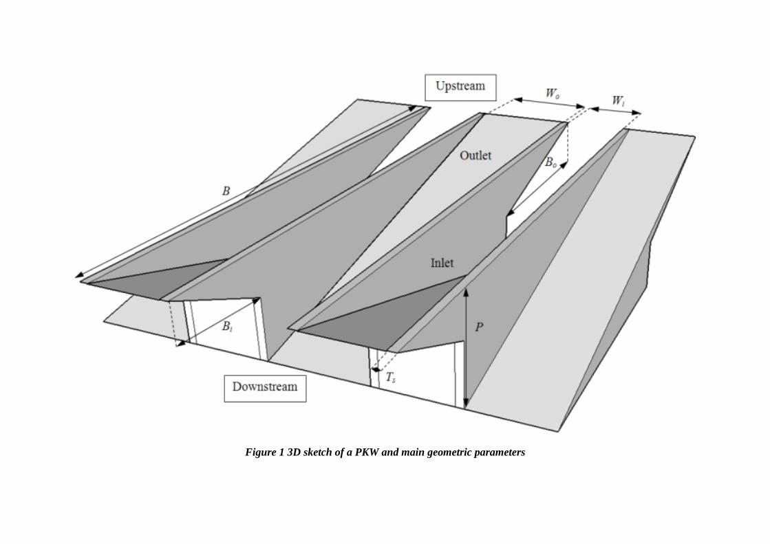
Figure 1 3D sketch of a PKW and main geometric parameters
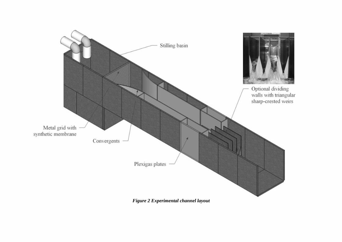
Figure 2 Experimental channel layout
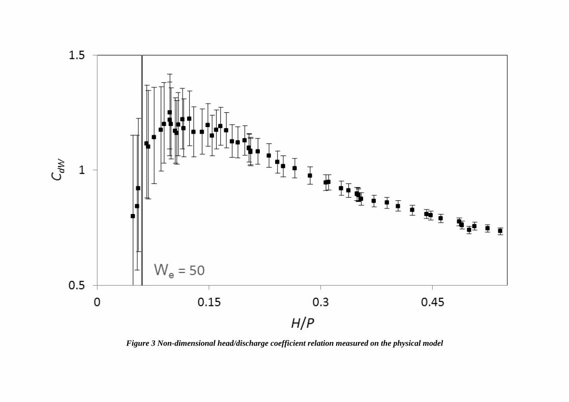
Figure 3 Non-dimensional head/discharge coefficient relation measured on the physical model
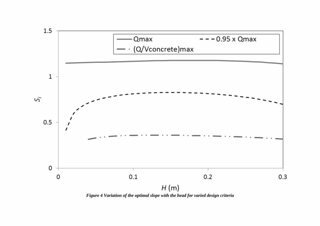
Figure 4 Variation of the optimal slope with the head for varied design criteria
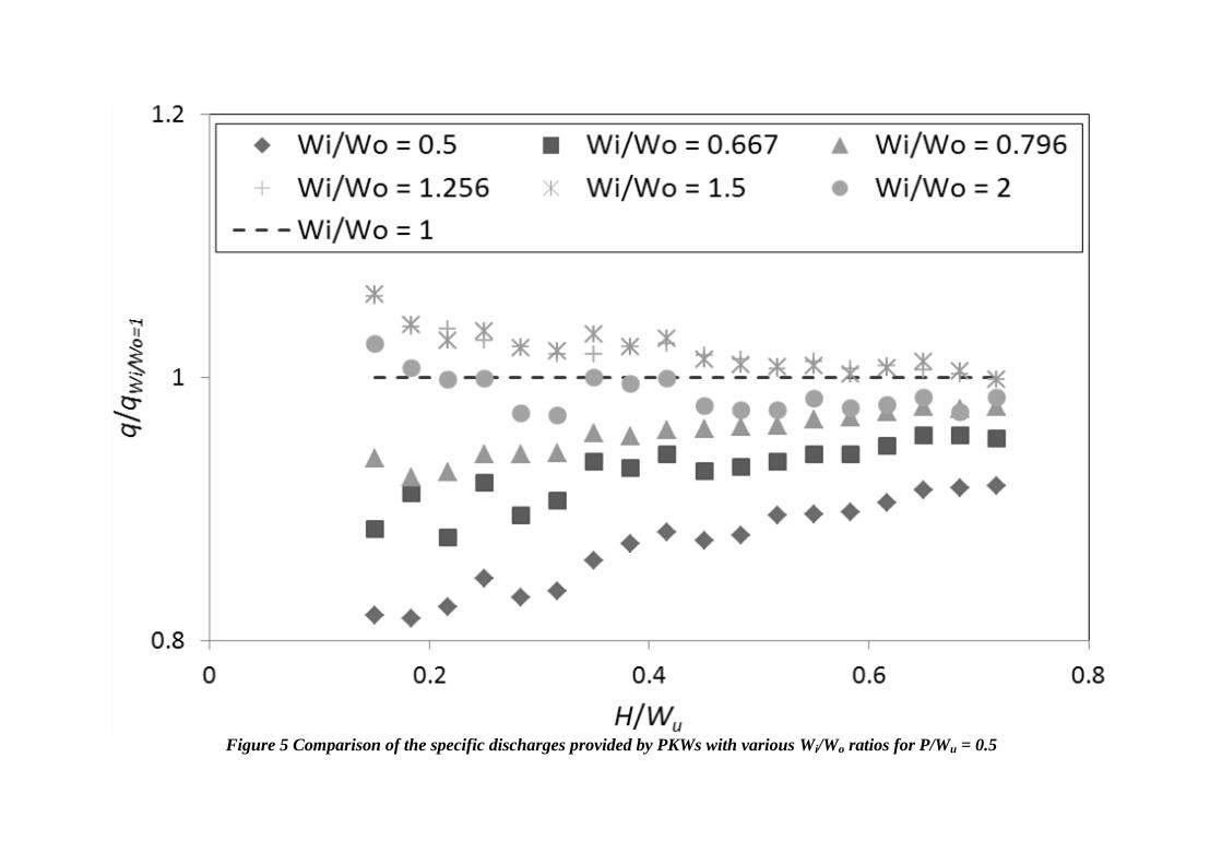
Figure 5 Comparison of the specific discharges provided by PKWs with various Wi/Wo ratios for P/Wu = 0.5

Figure 6 Comparison of the specific discharges provided by PKWs with various Wi/Wo ratios for P/Wu = 1.33
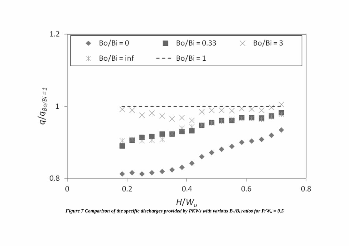
Figure 7 Comparison of the specific discharges provided by PKWs with various Bo/Bi ratios for P/Wu = 0.5
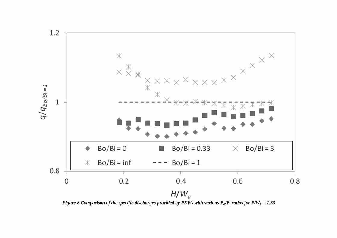
Figure 8 Comparison of the specific discharges provided by PKWs with various Bo/Bi ratios for P/Wu = 1.33