Embed Size (px)
Citation preview

Applied Energy 156 (2015) 390–397
Contents lists available at ScienceDirect
Applied Energy
journal homepage: www.elsevier .com/ locate/apenergy
Experiment on superadiabatic radiant burner with augmentedpreheating
http://dx.doi.org/10.1016/j.apenergy.2015.07.0620306-2619/� 2015 Elsevier Ltd. All rights reserved.
⇑ Corresponding author at: School of Mechanical Engineering, SungkyunkwanUniversity, 2066 Seobu-ro, Jangan-gu, Suwon, Gyeonggi-do 440-746, Republicof Korea. Tel.: +82 31 290 7465; fax: +82 31 290 5889.
E-mail address: [email protected] (O.C. Kwon).
H. Wu a, Y.J. Kim a, V. Vandadi b, C. Park c, M. Kaviany d, O.C. Kwon a,⇑a School of Mechanical Engineering, Sungkyunkwan University, Suwon, Gyeonggi-do 440-746, Republic of Koreab Department of Mechanical Engineering, University of Nevada, Reno, NV 89557, USAc Department of Mechanical and Aerospace Engineering, University of Missouri, Columbia, MO 65211, USAd Department of Mechanical Engineering, University of Michigan, Ann Arbor, MI 48109, USA
h i g h l i g h t s
� Potential of superadiabatic radiant burners (SRBs) is experimentally confirmed.� The SRB consists of two-layered porous media, a preheater and radiation rods.� The SRB can be operated at very fuel-lean condition due to enhanced heat recovery.� CO/NOx emissions are reduced compared with the conventional porous radiant burners.� The SRB is acceptable for practical applications.
a r t i c l e i n f o
Article history:Received 21 February 2015Received in revised form 22 June 2015Accepted 20 July 2015
Keywords:Porous burnersRadiant burnersHeat recirculationSuperadiabatic
a b s t r a c t
A radiant porous burner with augmented preheating (i.e., superadiabatic radiant burner, SRB) isexperimentally investigated. The porous alumina (Al2O3) burner with a square cross-section consists ofa small-pored upstream section for internally preheating the incoming gas mixture, a large-pored down-stream section for establishing flame, a preheater for externally recovering heat from the exiting flue gasand preheating the inlet air for the burner in addition to the internal heat recirculation in the small-poredupstream section, and radiation corridors for extracting heat from the flame and transferring it to radi-ating disk surfaces. Temperature distribution and combustion stability limits of flame in the SRB andthe nitrogen oxide (NOx) and carbon monoxide (CO) emissions are measured. Results show that theSRB can be operated even at very fuel-lean condition because of the internal and external heat recircu-lation, showing blow-off and flash-back limits for a given fuel-equivalence ratio. It is observed that thesuperadiabatic radiation temperature on the disk surfaces is higher than the flue gas temperature atthe same axial location, experimentally confirming the previous theoretical and computational resultsof SRBs. Improved performance of CO and NOx emissions compared with the conventional porous radiantburners also indicates that the SRB is acceptable for practical application.
� 2015 Elsevier Ltd. All rights reserved.
1. Introduction
In response to the current concerns over climate change andenergy security, there has been substantial interest in either devel-oping high-efficiency, low-emission combustion devices or findingalternative energy sources. Porous burners have been consideredas one possible technology for achieving the high-efficiency andlow-emission since they can recirculate heat from the burned hot
downstream gas to the unburned, incoming cold gas through theporous medium and thus operate under very fuel-lean condition[1,2]. In addition, it is known that the porous burners have the fuelflexibility, implying that alternative and renewable fuels such aslow-calorific syngas from waste pyrolysis and landfill gas can beutilized [3].
Recently a novel radiant porous burner with augmented pre-heating (i.e., superadiabatic radiant burner, SRB) was suggestedand computationally investigated [4]. The SRB consists of asmall-pored upstream section for internally preheating the incom-ing gas mixture, a large-pored downstream section for establishingflame, a preheater for externally recovering heat from the exiting

H. Wu et al. / Applied Energy 156 (2015) 390–397 391
flue gas and preheating the inlet air for the burner in addition tothe internal heat recirculation in the small-pored upstream sec-tion, and radiation corridors for extracting heat from the flameand transferring it to radiating disk surfaces. The two-section por-ous burners have been studied by various researchers, since thesmall-pored upstream section can play a role as a flashbackarrestor as well as the internal preheater, and the interfacebetween the two sections can stabilize the flame over a wide rangeof flow rates [5–11]. It was shown that for fuel-lean conditions theexternal heat recirculation due to the preheater in addition to theinternal heat recirculation in the small-pored section can increasethe local flame temperature in the SRB beyond the adiabatic flametemperature. Also, extracting and conducting heat from thesuperadiabatic flame through the embedded radiation corridors(rods), each of which is composed of a finned stem and a radiationdisk at the downstream end with high thermal conductivity, theheat is radiated to the target at a higher temperature than the fluegas. Efficiencies of the superadiabatic radiant burner were found tobe remarkably enhanced compared with the conventional porousburners.
The concept of external heat recirculation by installing apreheater in a porous burner has not been extensively investigated,though some fundamental studies were reported [12]. Meanwhile,the incorporation of the superadiabatic burners into thermophoto-voltaic (TPV) systems in which the direct generation of electricitythrough thermal radiation is possible can be suggested since theradiation disk surfaces at the downstream end of the radiation cor-ridors are appropriate to effectively radiate heat into photovoltaiccells. Actually the concept of using porous burners instead ofconventional cylindrical combustors in the TPV systems has beensuggested [13], but the radiation of the heat that is generated fromflame into the photovoltaic cells without the radiation corridors isnot effective since the flame is submerged in the porous medium.Thus, the SRBs seem to have a significant improvement in the per-formance compared with the conventional porous burners, particu-larly for the specific applications such as TPV systems that requireeffective radiation to the target. Considering that the concept ofthe SRB has been suggested via a computational investigation, it isneeded to experimentally demonstrate it.
In view of the above considerations, in this study we aim toexperimentally demonstrate the novel concept of the SRB, withthe following specific objectives. The first objective is to designand fabricate a laboratory scale SRB for demonstrating the concept.The second objective is to measure the combustion stability limitsof fuel-lean propane (C3H8)/air flames in the SRB at normal tem-perature and pressure (NTP), including the blow-off (i.e.,high-stretch extinction) limits and the flashback (i.e.,low-stretch) limits, in order to provide the fundamental databaseof steady-state operating limits of the SRB. The third objective isto confirm the superadiabatic effects of the SRB. We measure thetemperature distribution in the porous medium to observe if thepeak flame temperature is higher than the adiabatic flame temper-ature of the corresponding fuel/air mixture. Temperatures of radi-ating disk surfaces and the flue gas at the same axial location arealso measured to observe if the former is higher than the latter.The fourth objective is to measure the nitrogen oxide (NOx) andcarbon monoxide (CO) emissions of the premixed C3H8/air flamesin the SRB in order to observe if the SRB can exhibit NOx and COreduction. Finally, we estimate the thermal efficiencies of the SRB.
The configuration of the designed SRB, the combustion stabilitylimits and temperature distribution of the premixed C3H8/airflames in the SRB, the superadiabatic effects of the SRB and theCO and NOx emissions and efficiencies of the SRB will be subse-quently presented, following the descriptions of the experimentalmethods used during this investigation.
2. Experimental methods
The superadiabatic radiant burner with two porous sections(i.e., two-layer porous media), radiation rods embedded in the por-ous media and a preheater is considered for the present investiga-tion since it is expected to experimentally demonstrate thesuperadiabatic effects. A diagram of the experimental apparatusused in this study is shown in Fig. 1. It consists of a test SRB, afuel–air mixture supply system, a ventilation system, thermocou-ples for measuring temperature distribution in the SRB, a gas ana-lyzer for measuring NOx and CO emissions and a digital camera(Sony A65) for recording flame and radiation images.
Air (21% oxygen (O2)/79% nitrogen (N2) in volume, purity>99.9%) and C3H8 (purity >99.9999%) are supplied respectively toa preheater and to a mixing chamber using commercial mass flowcontrollers (Aera: 0–5 slm and MKS: 0–200 slm) with accuracy±1.0% of full scale. The mass flow controllers are calibrated usinga bubble meter. Air is preheated through the preheater and thenit is delivered to the mixing chamber. The preheater is a spiralfin tube with the inner diameter of 10.2 mm (stainless steel,SUS316L) and is located between the downstream end of the por-ous medium of the SRB and the radiation disks of the radiationrods. Thus, heat in exhaust gas is recovered to preheat fresh airin the preheater. The preheated air and fuel are mixed in the mix-ing chamber and are issued from the bottom of a distributor(68 � 68 � 60 mm3) that is filled with stainless steel beads withan average bead diameter of 1.5 mm for obtaining uniform flow.The distributor is windowed to detect flashback using quartz.The preheated air–fuel mixture is fed into the porous medium ofthe SRB with uniform flow.
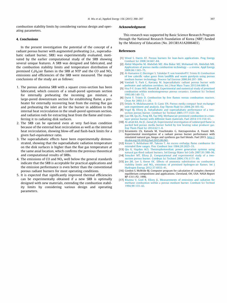
The test SRB is two-layered: a porous medium with fine alumina(Al2O3) foam (PM1: 60 ppi (pores per inch), 68.0 � 68.0 � 40.0 mm3,Drache Inc.) upstream and the other porous medium with coarseAl2O3 foam (PM2: 20 ppi, 68.0 � 68.0 � 40.0 mm3, Drache Inc.)downstream. The sides of porous media are surrounded by theheat-insulated case with thickness of 5.0 mm (SUS316L,78 � 78 � 140 mm3). The preheated air–fuel mixture is ignited atthe exhaust outlet of the burner by a torch-igniter. Once the mixtureis ignited, the flame moves backward and is stabilized in the PM2 oron the interface between the PM1 and PM2. Heat from the flame isextracted through the fins around the stem of the embedded radia-tion rods (silicon carbide, SiC), conducted through the stem and radi-ated at the radiation disk surface. Figs. 2 and 3 show the photographsof the assembled and disassembled SRB and the typical images of theradiating PM2 and disks, respectively.
R-type thermocouples with a bead diameter of 250 ± 20 lm andan accuracy of ± 0.25% are used to measure the temperature (T)distribution in the PM2. A stage on which the thermocouples arefixed can move through a hole that is drilled along the axial center-line, identifying the maximum flame temperature and its location.The preheated air temperature is measured using K-type thermo-couples with a bead diameter of 250 ± 20 lm and an accuracy of±0.75%. K-type thermocouples are also used to measure the radia-tion disk surface temperature and the exhaust gas temperature atthe same axial location as the disk surface. The disk surface tem-perature and the exhaust gas temperature are obtained by averag-ing measurements at the same axial location but different points.
The combustion stability limits of fuel-lean C3H8/air flames inthe SRB are measured by varying the fuel-equivalence ratio /and the burner inlet velocity V that is defined as the total volumeflow rate of the mixture divided by the cross-sectional area ofthe PM1. Propane has been chosen as fuel since it can be used inpractical applications. Once a flame is stabilized in the PM2 asaforementioned, / is set to a fixed value and then V is varied to findthe combustion stability limits. Given / two combustion stability
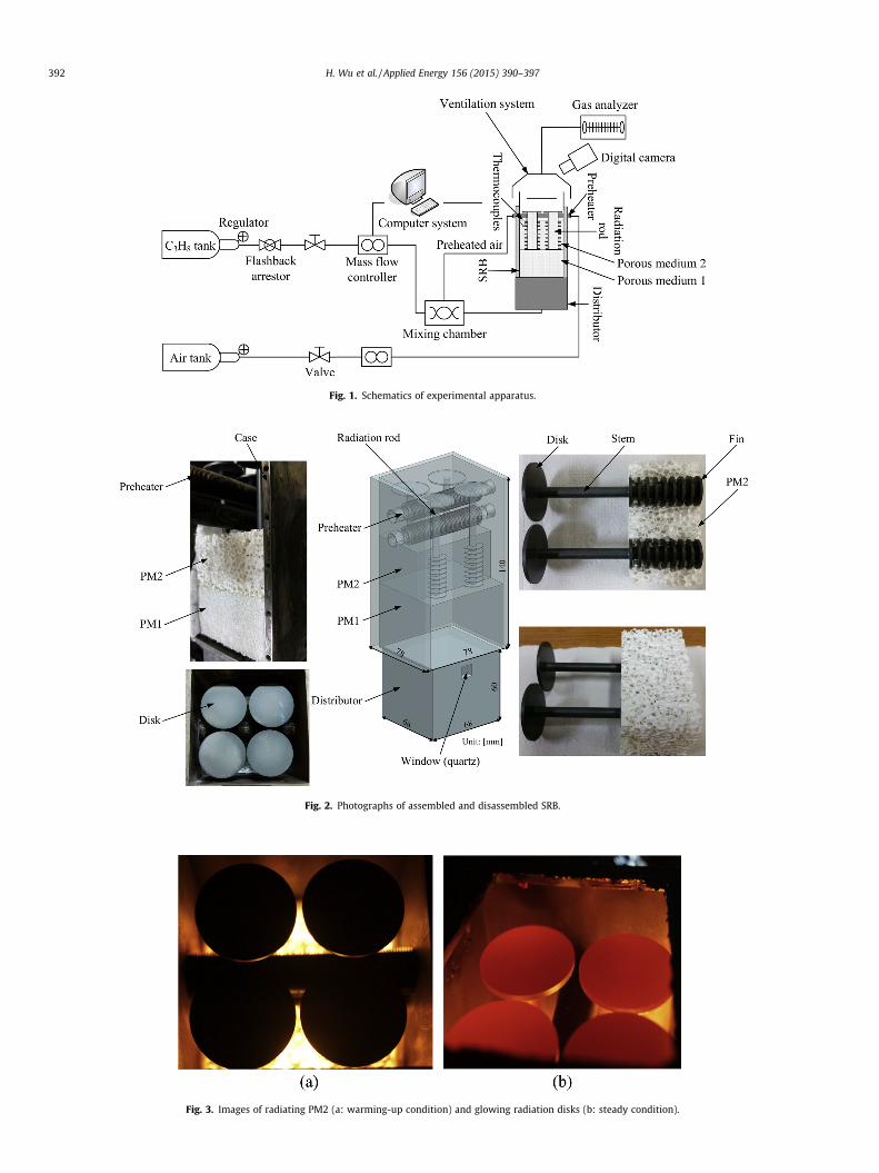
Fig. 1. Schematics of experimental apparatus.
Fig. 2. Photographs of assembled and disassembled SRB.
Fig. 3. Images of radiating PM2 (a: warming-up condition) and glowing radiation disks (b: steady condition).
392 H. Wu et al. / Applied Energy 156 (2015) 390–397

Table 1Specifications of major SRB components.
Components Parameters Values
PM1 Materials Alumina (Al2O3)Width (height) 68.0 mmLength 40.0 mmPorosity 0.835Pore size 60 ppiThermal conductivity 0.2 W/m K
PM2 Materials Al2O3
Width (height) 68.0 mmLength 40.0 mm
H. Wu et al. / Applied Energy 156 (2015) 390–397 393
limits are observed in general: the flashback (i.e., low-stretch) lim-its at low Vs and the blow-off (i.e., high-stretch extinction) limits athigh Vs. For some conditions no blow-off limits were obtainedbecause of the limited capability of the present apparatus. The con-centrations of NOx and CO are also measured in the ventilationtube using a gas analyzer (Testo 350-XL) with an accuracy of0.1–1.0 ppm: the probe is located on the center of the ventilationpath. Final results are obtained by averaging measurements of4–6 tests at each condition. Experimental uncertainties (95% confi-dence) for V and T are less than 5%. At NTP (298 ± 3 K) experimentswere carried out for / = 0.28–0.65 and V = 0.092–0.459 m/s.
Porosity 0.870Pore size 20 ppiThermal conductivity 0.1 W/m K
Radiation rods Materials Silicon carbide (SiC)Stem diameter 6.0 mmFin diameter 16.0 mmFin thickness 1.5 mmFin pitch 333 m�1
Disk diameter 32.0 mmDisk thickness 2.0 mmLength 90.0 mm
Preheater (fin tube) Materials Stainless steel (SS316L)Inner diameter 10.2 mmFin diameter 16.0 mmFin thickness 1.0 mmFin pitch 666 m�1
Tube thickness 0.5 mmLength 70.0 mm
3. Results and discussion
3.1. Configuration and dimensions of SRB
The final configuration and dimensions of the two-layered SRBwith a preheater and radiation rods as briefly described inSection 2 (Fig. 2) have been determined from the earlier computa-tional study of the concept of the SRB [4].
In order to use a simple structured, uniformly radiating burner,a square cylindrical configuration is chosen as the basic geometryof the SRB, and the external heat-recirculation concept of recover-ing heat from exhaust gas for preheating fresh air with the pre-heater is adopted. Heat from the flame stabilized in the PM2 isextracted through the fins around the stem of the embedded radi-ation rods, conducted through the stem and radiated at the radia-tion disk surface. Considering the limited capability of the presentmass flow controllers, the cross-sectional area of the PM 1 and PM2 has been determined, and four radiation rods are embedded intothe PM2. Based on the earlier computational study of the SRB [4]and the feasibility of fabrication, the pore size and length (thick-ness) of the PM1 and PM2 and the dimensions of the preheaterand the stem, fins and disk of the radiation rods have been alsodetermined. The measured preheated air temperature throughthe preheater for the present tests ranges from 453 to 501 K, i.e.,the temperature gain compared with the air supply temperaturewhen the preheater is not installed is 155–203 K, mainly beingaffected by the fuel-equivalence ratio. Specifications of the majorcomponents of the SRB, including the detailed dimensions andmaterials, are provided in Table 1.
Fig. 4. Combustion stability limits on _Q 00–/ diagram for fuel-lean premixed C3H8/airflames in SRB at NTP.
3.2. Combustion stability limits and temperature distribution in SRB
The combustion stability limits of fuel-lean C3H8/air flames inthe SRB are measured to provide the fundamental database ofsteady-state operating limits of the present SRB at NTP. Once aflame is stabilized in the PM2 as described in Section 2, / is setto a fixed value and then V or the firing flux of fuel ( _Q 00, based onlower heating value) is varied to find the combustion stabilitylimits.
Fig. 4 shows the combustion stability limits on a _Q 00–/ diagramfor fuel-lean premixed C3H8/air flames in the SRB at NTP. Given /two combustion stability limits are observed in general: the flash-back (i.e., low-stretch) limits at low _Q 00 s and the blow-off (i.e.,
high-stretch extinction) limits at high _Q 00 s. The flashback limitsare observed when the local burning velocity exceeds V, while theblow-off limits are observed due to insufficient residence times ofthe supplied fuel–air mixture. For some conditions no blow-off lim-its were obtained because of the limited capability of the presentapparatus, particularly the air supply system, since very high airflow rates are required for those conditions. Error bars for somedata points indicate typical variations for the present measure-ments. With increasing /, _Q 00 s at both the flashback and blow-off
limits increase. This tendency is observed since under thefuel-lean condition the burning velocities of C3H8/air flames alsoincrease with enhanced /. However, the blow-off limits increasemore sharply than the flashback limits, indicating that the formeris more sensitive to fuel composition than the latter and thus show-ing an effect of widening the stable operating range of the SRB forenhanced /. This observation was somewhat expected since similartendencies are observed for porous radiant burners with no exter-nal heat recirculation [14] and tube type gas burners [15]. The /limit where the flashback and blow-off limits are merged is esti-mated to be around 0.25, which is considered to be substantiallyextended compared with the limits for conventional porous radiantburners having a configuration and dimensions similar to the pre-sent SRB since preheated air is supplied to the burner inlet for theSRB while ambient air at normal temperature for the conventionalporous burners.

Fig. 6. Temperature distribution along axial centerline of PM2 for premixed C3H8/air flames of / = 0.48 and various fuel flow rates.
Fig. 7. Temperature distribution along axial centerline of PM2 for premixed C3H8/air flames of / = 0.60 and various fuel flow rates.
394 H. Wu et al. / Applied Energy 156 (2015) 390–397
Fig. 5 shows the combustion stability limits on a V–/ diagramfor fuel-lean premixed C3H8/air flames in the SRB at NTP. Similar
to the combustion stability limits on the _Q 00–/ diagram (Fig. 4),the flashback and blow-off limits are observed for a given /, exceptfor some conditions where the blow-off limits could not be mea-sured due to the limited capability of the present air supply sys-tem. Again, error bars for some data points indicate typicalvariations for the present measurements. With increasing /, Vs atboth the flashback and blow-off limits increase, showing a sharper
increase for the blow-off limits, similar to the _Q 00 limits in Fig. 4;however, the flashback limits are almost constant beyond / = 0.4.This tendency is observed since with increasing / the total volumeflow rate of the fuel–air mixture does not change remarkablythough fuel composition increases.
To understand flame structure in the present SRB at NTP and toprovide an additional database at steady-state operating conditionthe temperature distribution in the PM2 has been measured. Fig. 6shows the temperature distribution along the axial centerline ofthe PM2 for premixed C3H8/air flames of / = 0.48 and various fuelflow rates (1000–1400 sccm). All the flames in the figure are understeady-state operating condition, and each firing condition wasdetermined by controlling it to establish a flame at a proper posi-tion for various conditions. Also, those stable operating conditionsare confirmed from the combustion stability limits in Figs. 4 and 5.As shown in Fig. 6, all the flames are established quite downstreamfrom the interface between the PM1 and PM2. With increasing fuelflow rates the peak temperature is enhanced, though its locationdoes not seem to be sensitive to the flow rate within the currenttest range and thus no consistent tendency is observed, showingthe locations at the peak temperature between 20 and 25 mmdownstream from the interface. The tendency of the enhancedpeak temperature with increasing fuel flow rates is observed sincethe flame is intensified with the increased amount of supplied fuel.The superadiabatic effects of the present SRB shown in Fig. 6 willbe discussed in Section 3.3.
In order to observe the effects of / on flame structure in the SRB,the temperature distribution in the PM2 at enhanced / has beenmeasured. Fig. 7 shows the temperature distribution along theaxial centerline of the PM2 for premixed C3H8/air flames of/ = 0.60 and various fuel flow rates (1000–1400 sccm). Similar tothe flames of / = 0.48 in Fig. 6, all the flames in the figure are understeady-state operating condition and are established downstreamfrom the interface between the PM1 and PM2. Also, with increasingfuel flow rates temperature is generally enhanced due to the inten-sified burning. Although no consistent tendency is still observed
Fig. 5. Combustion stability limits on V–/ diagram for fuel-lean premixed C3H8/airflames in SRB at NTP.
for the location at the peak temperature in terms of fuel flow rates,however, all the flames somewhat shift upstream compared withthe flames at fuel-leaner condition in Fig. 6, showing the locationsat the peak temperature between 15 and 20 mm downstream fromthe interface. This is observed since the burning velocities areenhanced with increasing / and thus the fuel–air mixture burnsrelatively fast for a fixed fuel flow rate. The flame location in thePM2 is expected to be one of the important design parametersfor the practical applications of the SRB, e.g., TPV devices. Forinstance, if the flame is established downstream in the PM2, tem-perature of the radiation disks can increase and then photovoltaicperformance may improve. Also, the effects of preheating air in thepreheater of the SRB can be enhanced. However, high exhaust gastemperature cannot be avoided, implying that the overall systemefficiency degrades. Thus, further studies regarding the effects ofthe flame position in the SRB are needed when the overall perfor-mance of practical systems is considered. Again, the superadiabaticeffects of the present SRB shown in Fig. 7 will be discussed inSection 3.3.
3.3. Superadiabatic effects
The superadiabatic effects of the SRB are examined to experi-mentally confirm the unique features, comparing the measured

H. Wu et al. / Applied Energy 156 (2015) 390–397 395
peak flame temperature in the PM2 with the adiabatic flame tem-perature as well as temperature of radiating disk surfaces with theflue gas at the same axial location.
Figs. 6 and 7 which show the temperature distribution in thePM2 for the fuel-lean premixed C3H8/air flames as discussed inSection 3.2 also include the adiabatic flame temperature (AFT) ofthe corresponding fuel–air mixtures. The adiabatic flame tempera-ture is computed using the NASA CEA (Chemical Equilibrium withApplications) code [16]. As shown in Fig. 6 the peak temperaturefor all the flames is higher than the AFT, which indicates thesuperadiabatic effects of the SRB. Considering heat losses to thesurroundings even with thermal insulation under practical operat-ing condition, this superadiabatic effect is remarkable. For exam-ple, the peak temperature is much higher than the actual AFTthat is estimated when 10% heat losses are assumed. The AFTand the AFT with 10% heat losses for the premixed C3H8/air flameof / = 0.48 at NTP are respectively 1456 and 1310 K, indicating thedifference between the AFT and the maximum peak temperature of124 K (i.e., the maximum peak temperature 8.5% higher than theAFT). Fig. 7 for the flames of the enhanced / (= 0.60) also showsa similar observation with the AFT of 1700 K, the AFT with 10%heat losses of 1530 K and the difference between the AFT and themaximum peak temperature of 150 K (i.e., the maximum peaktemperature 8.8% higher than the AFT). Thus, the superadiabaticeffects do not change significantly with / variations, though flamessomewhat shift upstream with increasing /. Of course, thesesuperadiabatic effects of the SRB are observed due to the externalheat recirculation through the preheater as well as the internalheat recirculation through the PM1.
In addition to the superadiabatic effects in terms of the peaktemperature in the PM2, temperature of radiating disk surfacesand the flue gas at the same axial location are also measured toobserve if the former is higher than the latter, which is expectedfrom the earlier computational study of the concept of the SRB[4]. Fig. 8 shows the measured disk and flue gas temperature atthe same axial location in terms of fuel flow rates for premixedC3H8/air flames of / = 0.45 in the SRB at NTP. Both the disk and fluegas temperatures increase with increasing fuel flow rates becausethe burning in the PM2 is intensified. Due to the superadiabaticeffects of the SRB, i.e., the preheating and the separate heat transferthrough the radiation rods having high thermal conductivity, theradiating disk surface temperature is higher than the flue gas tem-perature for all the tests. The difference between two temperaturesis 53–67 K, which seems to be reasonable since the computationalstudy where no heat losses to the surroundings (particularly
Fig. 8. Disk and flue gas temperature in terms of fuel flow rates for premixed C3H8/air flames of / = 0.45 in SRB at NTP.
through the side walls of the burner case) are assumed showsthe difference up to 81 K [4], though the dimensions of the SRBand the test conditions are somewhat different from those in thepresent study. The disk temperature higher than the flue gas tem-perature may result in higher radiation efficiency, which will bediscussed in Section 3.4. Thus, the results in Figs. 6–8 experimen-tally and clearly demonstrate the superadiabatic effects of the SRB.
3.4. CO/NOx emissions and efficiencies
In order to evaluate if the SRB can exhibit CO and NOx reductioncompared with conventional gas burners for its practical applica-tion, the CO and NOx emissions of the premixed flames in theSRB have been measured. Also, the thermal efficiencies of the pre-sent SRB are estimated, though it has not been optimally designedconsidering various parameters.
Fig. 9 shows CO emissions from the exhaust gas as a function offuel flow rates for premixed C3H8/air flames of variousfuel-equivalence ratios (/ = 0.3–0.6) in the SRB at NTP. In general,the CO concentration is below 25 ppm, except for very fuel-leanand low fuel flow rate conditions. This level of CO emissions indi-cates that the SRB is acceptable for practical applications and theemission performance is even better than the conventional porousradiant burners for most operating conditions [17]. At veryfuel-lean conditions, CO emissions rapidly increase with decreas-ing fuel flow rates. This tendency is observed since the flame tem-perature is very low and thus oxidation (to carbon dioxide, CO2)rates are reduced. At moderate to high fuel flow rates (>1400 sccm)CO emissions do not seem to be sensitive to both the fuel flow rateand /. Considering that CO emissions are expected to be sensitiveto flame location since the oxidation time is reduced as the flameapproaches the exit plane of the PM2 [17], this observation seemsto be reasonable because flame does not move remarkably at thoseconditions, particularly for various fuel flow rates, as discussed inSection 3.2. If fuel flow rates increase further beyond the presenttest conditions, CO emissions are expected to increase due to thelimited oxidation time. As briefly discussed in Section 3.2 (Fig. 6),further studies regarding the effects of the flame position on theSRB performance, including CO emissions, are needed when theoverall performance of practical systems is considered.
The emissions of NOx from the exhaust gas as a function of fuelflow rates for premixed C3H8/air flames of various fuel-equivalenceratios (/ = 0.3–0.6) in the SRB at NTP are given in Fig. 10. All theNOx concentrations in the figure are corrected to 15% O2. For a
Fig. 9. CO emissions from exhaust gas as function of fuel flow rates for premixedC3H8/air flames of various fuel-equivalence ratios in the SRB at NTP.

Fig. 11. Thermal efficiencies as function of fuel flow rates for premixed C3H8/airflames of various fuel-equivalence ratios in the SRB at NTP.
396 H. Wu et al. / Applied Energy 156 (2015) 390–397
given / the NOx concentration increases with increasing fuel flowrates in general, which is observed since the peak temperature thatis enhanced due to the intensified burning (as shown in Figs. 6 and7) strongly affects NOx emissions via a thermal mechanism. For afixed fuel flow rate, however, no consistent tendency in terms of/ is observed. Actually, some earlier studies on the NOx emissionsof porous radiant burners have shown conflicting results, i.e., dif-ferent tendencies of emissions for varying / and V [9,17]. Thus,the effects of / and V on NOx emissions are less clear. This uncleartendency seems to be observed since the peak temperature thatstrongly affects NOx emissions via a thermal mechanism, particu-larly for fuel-lean condition, varies with varying / and V, but simul-taneously the residence time of burned gas also varies due to theflame position that is changed with / and V, which may compen-sate the effects of the varied peak temperature. Also, the earlierstudy shows that NOx emissions can be substantially reducedwhen the materials of porous medium are replaced, e.g., SiC [9].Thus, further studies regarding the effects of the SRB materials aswell as the flame position on the SRB performance (includingNOx emissions) are needed when the overall performance of prac-tical systems is considered. Considering that the absolute NOx con-centration is between 2 and 7 ppm for all the present testconditions, however, finding a general tendency may not be mean-ingful since any variations are likely to be within the measurementerror. This level of NOx emissions, which is well below the generalstandards, e.g., 70 ppm for commercial burners by SouthernCalifornia Emission Standards, indicates that the SRB is acceptablefor practical applications and the emission performance is evenbetter than the conventional porous radiant burners for most oper-ating conditions [17].
As a final item of investigation, the thermal efficiencies of thepresent SRB are estimated and given in Fig. 11, which shows ther-mal efficiencies as a function of fuel flow rates for premixedC3H8/air flames of various fuel-equivalence ratios (/ = 0.3–0.6) inthe SRB at NTP. In the present study, the thermal efficiency isdefined as follows:
g ¼_Q f � _Q exh
_Q f
¼ 1�_mexhcp;exhðTexh � TambÞ
_Q f
ð1Þ
where _Q f , _Q exh, _mexh, cp,exh, Texh and Tamb are the input heat power offuel (based on lower heating value), the exhausted heat rate, themass flow rate of the exhaust gas, the specific heat of the exhaustgas at constant pressure, the exhaust gas temperature behind the
Fig. 10. NOx emissions from exhaust gas as function of fuel flow rates for premixedC3H8/air flames of various fuel-equivalence ratios in the SRB at NTP.
preheater and the ambient temperature, respectively. As shown inthe figure, g decreases with increasing fuel flow rates, due toenhanced heat losses even with the increased fuel input.Meanwhile, g increases with increasing /, which is predicted fromthe earlier computational study showing a similar tendency up to /� 0.5 until the flame moves to the burner inlet and thus more radi-ation loss occurs [4]. According to Eq. (1), the thermal efficiencies ofthe SRB are expected to be enhanced compared with the conven-tional porous radiant burners since Texh decreases due to the sub-stantial heat recovery through the preheater. Actually, the earliercomputational study of the SRB has shown g even higher than40% under the optimized condition compared with at most 25%for conventional porous radiant burners [4]. Of course, such a sub-stantial improvement in g can be attributed to the unique feature ofthe SRB, the external heat recirculation via the preheater and theefficient heat transfer through the radiation rods. For the configura-tion and materials of the present SRB under the present test condi-tions, however, g is lower than 25%, which is just a similar level tothe conventional porous radiant burners. This significant differencebetween the earlier prediction and the present measurements in gof the SRB seems to be caused by the difference between the idealcomputational condition and the actual experimental condition.For instance, it is expected that there are remarkable heat losses,though the side walls of the SRB are assumed to be perfectly insu-lated for the computations. Also, a small gap at the interfacebetween the PM1 and PM2, which cannot be completely avoidedin the experiments, plays a role as a flashback arrestor along withthe small-pored upstream PM1. Since the interface is ideally consid-ered without any physical gap for the computations, however, theflame can move into the porous medium just with smaller pores(PM1) through it, not resulting in the flashback extinction.Actually, most computed flames have been predicted to be stabi-lized in the PM1 [4], while the present measured flames areobserved only in the PM2. Finally, the present SRB has not beenoptimally designed considering various parameters as aforemen-tioned. Thus, in the present investigation neither the configurationand dimensions nor the test operating conditions have been opti-mized. Although the computational and experimental studies havebeen conducted using the SRBs with different configurations at dif-ferent test conditions, a rough comparison of the results indicatesthe present values of g under non-optimized conditions seem tobe reasonable. Thus, it is expected that significantly improvedthermal efficiencies can be experimentally obtained if a new SRBis optimally designed with new materials, extending the
H. Wu et al. / Applied Energy 156 (2015) 390–397 397
combustion stability limits by considering various design and oper-ating parameters.
4. Conclusions
In the present investigation the potential of the concept of aradiant porous burner with augmented preheating (i.e., superadia-batic radiant burner, SRB) was experimentally evaluated, moti-vated by the earlier computational study of the SRB showingseveral unique features. A SRB was designed and fabricated, andthe combustion stability limits and temperature distribution ofpremixed C3H8/air flames in the SRB at NTP and the CO and NOx
emissions and efficiencies of the SRB were measured. The majorconclusions of the study are as follows:
1. The porous alumina SRB with a square cross-section has beenfabricated, which consists of a small-pored upstream sectionfor internally preheating the incoming gas mixture, alarge-pored downstream section for establishing flame, a pre-heater for externally recovering heat from the exiting flue gasand preheating the inlet air for the burner in addition to theinternal heat recirculation in the small-pored upstream section,and radiation rods for extracting heat from the flame and trans-ferring it to radiating disk surfaces.
2. The SRB can be operated even at very fuel-lean conditionbecause of the external heat recirculation as well as the internalheat recirculation, showing blow-off and flash-back limits for agiven fuel-equivalence ratio.
3. The superadiabatic effects have been experimentally demon-strated, showing that the superadiabatic radiation temperatureon the disk surfaces is higher than the flue gas temperature atthe same axial location, which confirms the previous theoreticaland computational results of SRBs.
4. The emissions of CO and NOx well below the general standardsindicate that the SRB is acceptable for practical applications andthe emission performance is even better than the conventionalporous radiant burners for most operating conditions.
5. It is expected that significantly improved thermal efficienciescan be experimentally obtained if a new SRB is optimallydesigned with new materials, extending the combustion stabil-ity limits by considering various design and operatingparameters.
Acknowledgment
This research was supported by Basic Science Research Programthrough the National Research Foundation of Korea (NRF) fundedby the Ministry of Education (No. 2013R1A1A2006403).
References
[1] Wood S, Harris AT. Porous burners for lean-burn applications. Prog EnergyCombust Sci 2008;34:667–84.
[2] Abdul Mujeebu M, Abdullah MZ, Abu Bakar MZ, Mohamad AA, Abdullah MK.Applications of porous media combustion technology – a review. Appl Energy2009;86:1365–75.
[3] Al-Hamamre Z, Diezinger S, Talukdar P, von Issendorff F, Trimis D. Combustionof low calorific value gases from landfills and waste pyrolysis using porousmedium burner technology. Process Saf Environ 2006;84:297–308.
[4] Vandadi V, Park C, Kaviany M. Superadiabatic radiant porous burner withpreheater and radiation corridors. Int J Heat Mass Trans 2013;64:680–8.
[5] Hsu P-F, Evans WD, Howell JR. Experimental and numerical study of premixedcombustion within nonhomogeneous porous ceramics. Combust Sci Technol1993;90:149–72.
[6] Durst F, Trimis D. Combustion by free flames versus combustion reactors.Clean Air 2002;3:1–20.
[7] Delalic N, Mulahasanovic D, Ganic EN. Porous media compact heat exchangerunit-experiment and analysis. Exp Therm Fluid Sci 2004;28:185–92.
[8] Vogel BJ, Ellzey JL. Subadiabatic and superadiabatic performance of a two-section porous burner. Combust Sci Technol 2005;177:1323–38.
[9] Gao HB, Qu ZG, Feng XB, Tao WQ. Methane/air premixed combustion in a two-layer porous burner with different foam materials. Fuel 2014;115:154–61.
[10] Al-attab KA, Ho JC, Zainal JA. Experimental investigation of submerged flame inpacked bed porous media burner fueled by low heating value producer gas.Exp Them Fluid Sci 2014;62:1–8.
[11] Keramiotis Ch, Katoufa M, Vourliotakis G, Hatziapostolou A, Founti MA.Experimental investigation of a radiant porous burner performance withsimulated natural gas, biogas and synthesis gas fuel blends. Fuel 2015. http://dx.doi.org/10.1016/j.fuel.2015.06.041.
[12] Kotani Y, Behbahani HF, Takeno T. An excess enthalpy flame combustor forextended flow ranges. Proc Combust Inst 1984;20:2025–33.
[13] Qiu K, Hayden ACS. Thermophotovoltaic power generation systems usingnatural gas-fired radiant burners. Sol Energy Mater Sol Cells 2007;91:588–96.
[14] Smucker MT, Ellzey JL. Computational and experimental study of a two-section porous burner. Combust Sci Technol 2004;176:1171–89.
[15] Joo JM, Lee S, Kwon OC. Effects of ammonia substitution on combustionstability limits and NOx emissions of premixed hydrogen-air flames. Int JHydrogen Energy 2012;37:6933–41.
[16] Gordon S, McBride BJ. Computer program for calculation of complex chemicalequilibrium compositions and applications. Cleveland, OH, USA: NASA ReportRP-1311-P2; 1996.
[17] Khanna V, Goel R, Ellzey JL. Measurements of emissions and radiation formethane combustion within a porous medium burner. Combust Sci Technol1994;99:133–42.


![Development of a non-premix radiant burner...burners with a smaller fue] input. The restrietion on burner dimensions has Jater been changed to: height x width: ~ 1000 mm x 1000 mm](https://img.pdfslide.us/doc/110x75/5f28213b13a9b76f5e104707/development-of-a-non-premix-radiant-burner-burners-with-a-smaller-fue-input.jpg)