Embed Size (px)
Citation preview

1/16
Figure (1-1): Basic Operation
of a dc Generator.
EXPERIMENT N0.1
DC GENERATORS
I. Objectives:
To investigate the principles of operation of dc generators by
measure some of the characteristics of a separately excited dc generator,
dc shunt generator, dc series generator, and dc compound generator such
as, no-load characteristics, and terminal characteristics. Also to be
familiar with the main advantages and disadvantages of these types of dc
generators by comparing the main features among them, specially the
voltage regulation and control methods of the output voltage.
II. Equipment: 1. D.C Machine (as a Generator) MV 1006 / TERCO 1
2. D.C Machine (as a Motor) MV 1028 / TERCO 1
3. Torque measuring unit MV 1051 / TERCO 1
4. Power supply MV 1300 / TERCO 1
5. Shunt regulator MV 1905 / TERCO 2
6. Resistor load MV 1100 / TERCO 1
7. Load switch MV 1500 / TERCO 1
8. Multimeters 5
III. Theory:
Direct current machines are energy transfer devices. These machines
can function as either a motor or a generator. DC motors and generators
have the same basic construction, differing primarily in the energy
conversion. In DC generators, the three conditions that necessary to
induce voltage are: magnetic field, conductor, and relative motion
between them. So the basic DC generator has four basic parts: magnetic
field, single conductor or loop, commutator and brushes, as shown in
Fig.(1-1).

EXPERIMENT NO.(1) DC GENERATORS
2/16
Figure (1-2): Left-Hand Rule for
Generators.
A single conductor, shaped in the form of a loop, is positioned
between the magnetic poles. As long as the loop is stationary, the
magnetic field has no effect (no relative motion). If the loop is rotated,
there will be a relative motion between the magnetic field and the
conductor, so an EMF (voltage) will induce into it. The magnitude of the
induced EMF depends on the field strength and the rate at which the flux
lines are cut, as given by the following equation.
Eg = K (1-1)
Where:
Eg = generated voltage
K = constant, depending on the construction of the machine
= magnetic flux strength
= angular speed
The direction of the induced current flow can be determined
using the "left-hand rule" for generators, as shown in Fig.(1-2).
Applying the left-hand rule to both sides of the loop will show that
current flows in a counter-clockwise direction in the loop
Commutator converts the AC voltage generated in the rotating
loop into a DC voltage. In a simple one-loop generator, the commutator
is made up of two semi cylindrical pieces of a smooth conducting
material, usually copper, separated by an insulating material. Each half of
the commutator segments is permanently attached to one end of the
rotating loop.
Brushes usually made of carbon, slides along the commutator as it
rotates so the brushes make contact with each end of the loop. Each brush
slides along one half of the commutator and then along the other half.
Every time the ends of the loop reverse polarity, the brushes
switch from one commutator segment to the next. This means that one
brush is always positive with respect to the other. The voltage between
the brushes fluctuates in amplitude between zero and some maximum
value, but it is always of the same polarity as shown in Fig.(1-3).

EXPERIMENT NO.(1) DC GENERATORS
3/16
%100
fl
flnl
V
VVVR
Figure (1-4): The magnetization curve of a
generator for a fixed speed.
The magnetic field may be supplied by either a permanent magnet
or an electromagnet. The magnetic fields in DC generators are most
commonly provided by electromagnets. The current which flow through
the electromagnet conductors to produce the magnetic field is known as
the field excitation current and can be supplied to the field winding in one
of two ways; it can be fed from a separate DC source (Separately excited
generator) or it can come directly from the output of the generator, in that
it is called a self-excited generator. In a self-excited generator, the field
winding is connected directly to the generator output. The field may be
connected in parallel with the output (Shunt generator), in series with the
output (Series generator), or a combination of the two (Compound
generator).
The field current produces a flux in the machine core in accordance
with its magnetization curve, and since EA is directly proportional to the
flux at constant speed, the relation between EA and If (no-load
characteristic) will be as shown in Fig.(1-4).
Dc Generators are compared by their voltages, power ratings,
efficiencies, and voltage regulations. Voltage regulation (VR) is defined
by the equation
(1-2)
EA
If
= o
Figure (1-3): Commutation in a DC Generator.
EXPERIMENT NO.(1) DC GENERATORS
4/16
AAAT RIEV
Figure (1-5): A separately excited dc
generator.
The Separately Excited DC Generator
The equivalent circuit of such a machine is shown in Fig.(1-5). In
this figure the armature circuit is represented by an ideal voltage source
(EA) and a resistor (RA). The field coils are represented by inductor (Lf)
and resistor (Rf). It is clear that the armature current (IA) is equal to the
load current (IL) in a separately excited generator. By Kirchhoff's voltage
low, the terminal voltage is:
(1-3)
According to the previous equation the terminal characteristic (VT
versus IL) of a separately excited generator is a straight line as shown in
Fig.(1-6-a). In generators without compensating windings, an increase in
IA causes an increase in armature reaction and armature reaction causes
flux weakening. This flux weakening causes a decrease in EA= K
which further decreases the terminal voltage of the generator as show in
Fig.(1-6-b)
There are two possible ways to control the output voltage:
1. Change the speed of rotation. If then EA = K increases, so VT =
EA-IARA increases too.
2. Change the field current. If If increases then the flux in the machine
increases. Therefore EA = K increases and VT = EA-IARA
increases too.
RA
+
-
RF
LF
Load
IL IA IF
EA VT
+
-
VF
AR drop
IL
VT
EA RAIA
IL
VT
EA
RAIA drop
Figure (1-6): The terminal characteristic of a separately excited dc
generator with(a) and without(b) compensating windings.
(a) (b)

EXPERIMENT NO.(1) DC GENERATORS
5/16
Figure (1-7): The equivalent circuit
of a shunt dc generator.
Figure (1-8): Voltage buildup on starting
in a shunt dc generator.
The Shunt-Wound DC Generators
When the field windings is connected in parallel with the armature
of the generator, the generator is called a shunt-wound generator (Fig.(1-
7)). In this circuit the armature current supplies both the field current and
the load, so
The Kirchhoff's voltage low equation for the armature circuit is:
The voltage buildup in a dc generator depends on the presence of a
residual flux in the poles of the generator as shown in Fig.(1-8)
There are several possible causes for the voltage to fail to buildup
during starting. Among them are:
1- There may be no residual flux
2- The direction of rotation of the generator or the field current may have
been reversed which produces a flux opposing the residual flux instead
of adding to it.
3- The field resistance may be adjusted to a high value so the field
current will be very small and the voltage never buildup.
AAAT RIEV
RA
+
-
RF
LF
Load
IL IA
IF
EA VT
+
-
EA/VT
If
VT versus If
Ifnl
VTnl
EA versus If
Rf =VT/If
EResid
ual
LFA I I I

EXPERIMENT NO.(1) DC GENERATORS
6/16
Figure (1-9): The terminal
characteristic of a
shunt dc generator
.
Figure (1-10): The equivalent circuit of
a series dc generator.
As the load is increased, IA increases and then armature resistance
voltage drop increases, causing VT to decrease. However, when VT
decreases, the field current decreases and so the flux also decreases with
it. This causes EA to decrease which causes a further decrease in the
terminal voltage. By the effect of the armature reaction the terminal
voltage will decrease more and more as shown in Fig.(1-9)
As in the separately exited generator, there are two ways to control
the voltage of a shunt generator:
1. Change the speed of rotation.
2. Change the field current.
The Series-Wound DC Generators
When the field winding of the DC generator is connected in series
with the armature, the generator is called a series-wound generator
(Fig.(1-10)).
According to this equivalent circuit, it can be noted that
LFA III
and
(1-4)
Since the excitation current in a series-wound generator is the
same as the load current, the curve represents the relation between the
generated voltage (EA) and the load current, looks like the magnetization
)( SAAAT RRIEV
IL
VT
RAIA drop
Field weakening effect
A.R.
RA
+
-
RS LS
Load
IL IA IF
EA VT
+
-

EXPERIMENT NO.(1) DC GENERATORS
7/16
Figure (1-11): A series generator
terminal characteristic.
Figure (1-12): the equivalent circuit
of a compounded dc
generator.
curve. The IA(RA+RS) drop goes up by increasing load current which
reduces the terminal voltage as shown in Fig. (1-11).
The Compound DC Generators
Series and shunt generators have a disadvantage in that changes in
load current cause change in generator output voltage. One means of
supplying a stable output voltage is by using a compound generator.
A compound dc generator is a dc generator with both series and
shunt fields, connected so that the magnetomotive forces from the two
fields are additive (cumulatively compound) or subtractive (differentially
compound). Fig (1-12) shows the equivalent circuit of a compound dc
generator.
As load current increases the armature current increases which tends
to cause a decrease in the terminal voltage VT = EA- IA(RA+RS). In
cumulatively compound generator, increasing IA cause an increase in the
net flux which increases EA and VT. These two effects oppose each other,
one tending to decrease VT and the other tending to increase VT.
In case of few series turns the first effect will be dominant so the
terminal voltage decreases. This type of construction is called
undercompounded
If there are a few more series turns, then at first the flux
strengthening effect wins but as the load continues to increase, the
resistive drop becomes stronger. If VT at no load is equal to VT at full
load the generator is called flatcompounded.
IL
EA/VT
IA(RA+ RS) drop
+ Armature reaction
RA
+
-
RS LS
Load
IL IA
EA VT
+
-
RF
LF IF

EXPERIMENT NO.(1) DC GENERATORS
8/16
Figure (1-13): Terminal characteristic of
a compounded dc generator.
If the number of series turns is large, the effect that increases the
terminal voltage will be predominant and the generator is called
overcompounded. Fig.(1-13) shows the terminal characteristic of the
compound dc generator with all previous cases compared with the shunt
generator.
In differentially compounded generator, as the load is increased, IA
increases, causing decreasing in the net flux which in turn decreases the
induced voltage and VT. The resistive voltage drop will also reduce the
terminal voltage and so it will drops drastically by increasing the load
current as shown in Fig.(1-13).
IL
VT
Overcompounded
Flatcompounded
Undercompounded
Shunt
IFL
Differentially
compounded

EXPERIMENT NO.(1) DC GENERATORS
9/16
IV. Procedures:
Part 1: Separately excited dc generator
No-Load Characteristic
1.1 Connect the dc machine MV 1006 as a generator, and the dc machine
MV1028 as a motor in accordance with circuit diagram (1).
1.2 Make sure that the switch S is off and the two regulators are turned
to minimum value.
1.3 Set the field current of the dc motor to 0.7 A, increase the armature
voltage whereupon the motor starts rotating. Adjust the speed to
1400 rpm (this speed must be kept constant during the experiment).
1.4 Increase the field current of the generator in steps of 0.1 A up to
maximum (see ratings) for each step measure the terminal voltage.
1.5 Repeat step 1.4 after adjusting the speed to 1200 rpm
Load characteristic
1.6 Readjust the speed to 1400 rpm (this speed must be kept constant
during this part).
1.7 Adjust the shunt regulator of the generator to bring the voltage up to
220 V. Record the excitation current, this value must be kept
constant during this part of the experiment.
1.8 Turn the load resistor toward minimum load current. Turn on switch
S. By varying the load resistor increase the armature current in steps
of 1A up to maximum (see ratings), for each step read the terminal
voltage and the shaft torque.
1.9 Turn off the switch S, variable dc voltage, fixed dc voltage, and the
main power supply switches (don’t open the field circuit of the dc
motor while motor is running)

EXPERIMENT NO.(1) DC GENERATORS
10/16
Part 2: Shunt dc generator
2.1 Leave the dc machine MV1028 as it was, and reconnect the dc
machine MV1006 as a shunt dc generator as shown in circuit
diagram (2).
2.2 Restart the dc motor as in the previous part (step 1.3)
2.3 Adjust the shunt regulator of the dc generator to bring the terminal
voltage up to 220 V.
2.4 Turn the load resistor toward minimum load current. Turn on switch
S. By varying the load resistor increase the load current in steps of
1A up to 5A, for each step read the terminal voltage, the field
current and the shaft torque.
2.5 Turn off the switch S, variable dc voltage, fixed dc voltage, and the
main power supply switches (don’t open the field circuit of the dc
motor while motor is running)
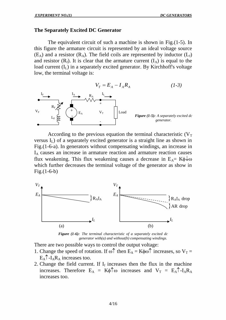
Part 3: Series dc generator
3.1 Leave the dc machine MV1028 as it was, and reconnect the dc
machine MV1006 as a series dc generator as shown in circuit
diagram (3).
3.2 Restart the dc motor as in the previous part (step 1.3)
3.3 Turn the load resistor toward minimum load current. Turn on switch
S. By varying the load resistor increase the load current in steps of
0.5A up to 5A, for each step read the terminal voltage and the shaft
torque.
3.4 Turn off the switch S, variable dc voltage, fixed dc voltage, and the
main power supply switches (don’t open the field circuit of the dc
motor while motor is running)

EXPERIMENT NO.(1) DC GENERATORS
11/16
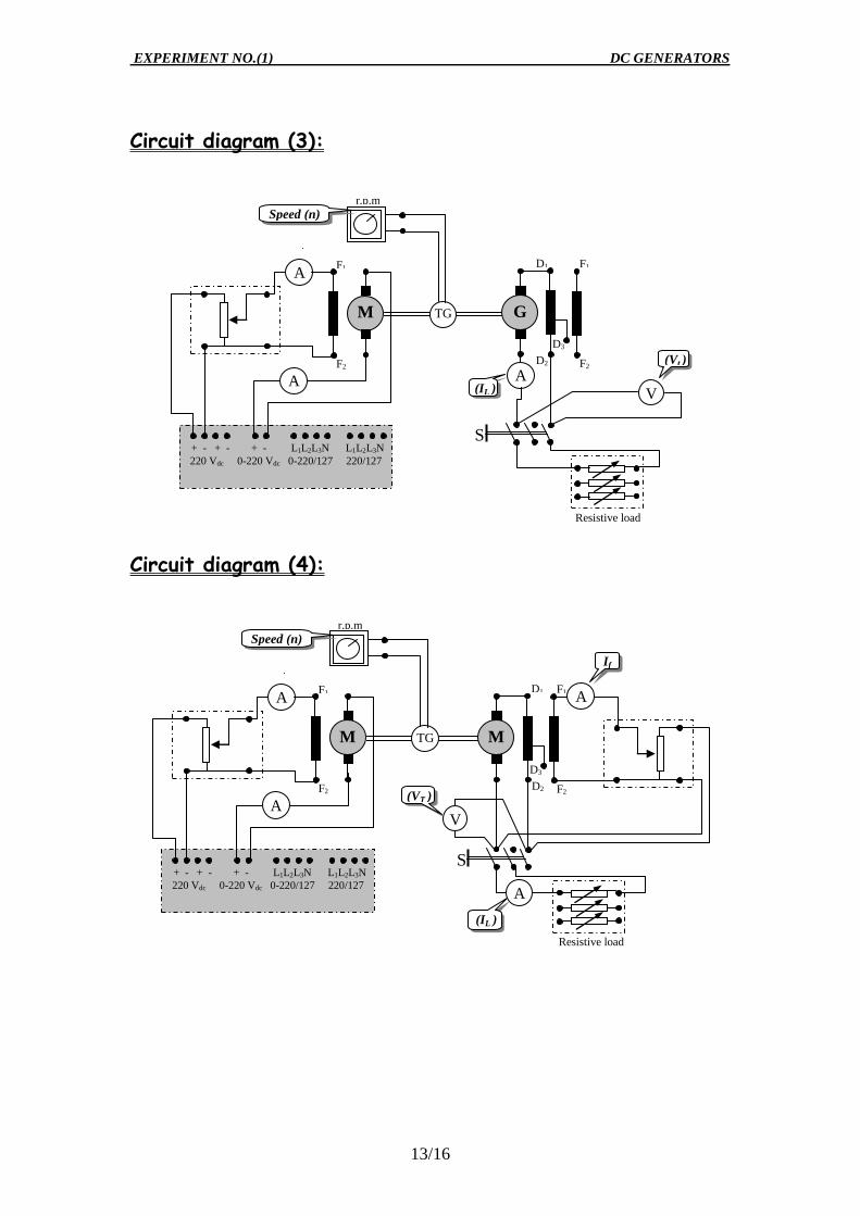
Part 4: Compound dc generator
4.1 Leave the dc machine MV1028 as it was, and reconnect the dc
machine MV1006 as a compound dc generator with 100% of the
series windings (Overcompounded) as shown in circuit diagram (4).
4.2 Restart the dc motor as in the previous part (step 1.3)
4.3 Adjust the shunt regulator of the dc generator to bring the terminal
voltage up to 220 V.
4.4 Turn the load resistor toward minimum load current. Turn on switch
S. By varying the load resistor increase the load current in steps of
1A up to 5A, for each step read the terminal voltage and the shaft
torque.
4.5 Turn off the switch S, variable dc voltage, fixed dc voltage, and the
main power supply switches (don’t open the field circuit of the dc
motor while motor is running).
4.6 Modify the circuit by using 70% of the series windings
(Flatcompounded) and then repeat step 4.3 to 4.5.
4.7 Again modify the circuit but now with only 30% of the series
windings (Undercompounded) and then repeat step 4.3 to 4.5

EXPERIMENT NO.(1) DC GENERATORS
12/16
Circuit diagram (1):
Circuit diagram (2):
+ - + - + - L1L2L3N L1L2L3N
220 Vdc 0-220 Vdc 0-220/127 220/127
TG
r.p.m
A
F2
F1
M
Resistive load
S
A
A
Speed (n)
(VT )
If
(IL )
D3
D2
D1
M
F2
F1
A
V
+ - + - + - L1L2L3N L1L2L3N
220 Vdc 0-220 Vdc 0-220/127 220/127
TG
r.p.m
A
F2
F1
M
Resistive load
S
A
A
Speed (n)
(VT )
If
(IL )
D3
D2
D1
M
F2
F1
A
V
EXPERIMENT NO.(1) DC GENERATORS
13/16
Circuit diagram (3):
Circuit diagram (4):
A
+ - + - + - L1L2L3N L1L2L3N
220 Vdc 0-220 Vdc 0-220/127 220/127
TG
r.p.m
A
F2
F1
M
Resistive load
S
A
Speed (n)
(Vt )
(IL )
V
D2
D1
G
D3
F2
F1
+ - + - + - L1L2L3N L1L2L3N
220 Vdc 0-220 Vdc 0-220/127 220/127
TG
r.p.m
A
F2
F1
M
Resistive load
S
A
A
Speed (n)
(VT )
If
(IL )
D3
D2
D1
M
F2
F1
A
V

EXPERIMENT NO.(1) DC GENERATORS
14/16
V. Results:
Part 1: Separately excited dc generator
No-Load Characteristic
Load characteristic
Part 2: Shunt dc generator
n=1400 rpm
IF (A) 0.0 0.1 0.2 0.3 0.4 0.5
Eg (V)
n=1400 rpm
IF (A) 0.0 0.1 0.2 0.3 0.4 0.5
Eg (V)
N=1400 rpm IF =
Measu
red IL (A) 0
Vt (V) 220
(Nm)
Ca
lcu
late
d Pin(w)
Pout(w)
(%)
n=1400 rpm
Mea
sure
d IL (A) 0 1 2 3 4 5
Vt (V) 220
IF (A)
(Nm)
Ca
lcu
late
d
Pin(w)
Pout(w)
(%)

EXPERIMENT NO.(1) DC GENERATORS
15/16
Part 3: Series dc generator
Part 4: Compound dc generator
n=1400rpm
Measu
red
IL (A) 0 0.5 1 1.5 2 2.5 3 3.5 4 4.5 5
Vt (V)
(Nm)
Calc
ula
ted
Pin(w)
Pout(w)
(%)
N=1400 rpm 100% of the series winding (Overcompounded)
Mea
sure
d
IL (A) 0
Vt (V) 220
(Nm)
Ca
lcu
late
d
Pin(w)
Pout(w)
(%)
n=1400 rpm 70% of the series winding (Flatcompounded)
Mea
sure
d
IL (A) 0
Vt (V) 220
(Nm)
Ca
lcu
late
d
Pin(w)
Pout(w)
(%)
n=1400 rpm 30% of the series winding (Undercompounded)
Measu
red
IL (A) 0
Vt (V) 220
(Nm)
Ca
lcu
late
d
Pin(w)
Pout(w)
(%)

EXPERIMENT NO.(1) DC GENERATORS
16/16
VI. Tasks:
a. In the same graph, draw the magnetization curve (Eg versus IF) for
the two different speeds according to the measured data in part 1.
b. Complete the tables in parts 1, 2, 3, and 4 by calculating the input
power (Pin = ), the output power (Pout =VtIL), and the efficiency
(in
out
P
P ) for each electrical load.
c. In the same graph, draw the terminal voltage versus the load
current of the separately excited, shunt, and series dc generator.
d. In the same graph, draw the terminal voltage versus the load
current for the different cases of the cumulatively compounded dc
generator and the shunt dc generator.
e. In the same graph, draw the efficiency () as a function of the load
current for the separately excited, shunt, series, and
flatcompounded dc generator.
f. According to the terminal characteristics drawn in C, is there any
effect of the armature reaction in this machine? How can this
problem be remedied?
g. Using the terminal characteristic of the separately excited dc
generator, determine approximately the internal resistance of the
armature of the dc generator (RA).
h. Calculate the voltage regulation of this dc generator in case of
separately, shunt, and series excitation. Calculate the voltage
regulation for the different cases of the cumulatively compounded
dc generator.
i. What is the critical resistance?
j. How can the different cases of the cumulatively compounded dc
generator (over, under, and flat) be gotten without changing the
number of series windings?
k. Explain how to control the output voltage for the different types of
the dc generator and how to reverse the voltage polarity?