Embed Size (px)
Citation preview

Experiment Instructions
HL 710 Air Duct Systems


HL 710 AIR DUCT SYSTEMS
All
right
s re
serv
ed, G
.U.N
.T. G
erät
ebau
, Bar
sbüt
tel,
Ger
man
y 01
/201
1
Experiment Instructions
Dipl.-Ing. Klaus-Jürgen Radtke
Dipl.-Geogr. Uta Linke
This manual must be kept by the unit.
Before operating the unit: - Read this manual.
- All participants must be instructed on handling of the unit and, where appropriate,
on the necessary safety precautions.
i
Version 1.0 Subject to technical alterations

HL 710 AIR DUCT SYSTEMS
ii

HL 710 AIR DUCT SYSTEMS
All
right
s re
serv
ed, G
.U.N
.T. G
erät
ebau
, Bar
sbüt
tel,
Ger
man
y 01
/201
1
Table of Contents
1 Introduction . . . . . . . . . . . . . . . . . . . . . . . . . . . . . . . . . . . . . . . . . . . . . . . . . 1
1.1 Purpose of the device, audience and learning objectives . . . . . . . . . . 1
1.2 Didactic notes for teachers . . . . . . . . . . . . . . . . . . . . . . . . . . . . . . . . . 2
2 Safety . . . . . . . . . . . . . . . . . . . . . . . . . . . . . . . . . . . . . . . . . . . . . . . . . . . . . . 5
2.1 Intended use . . . . . . . . . . . . . . . . . . . . . . . . . . . . . . . . . . . . . . . . . . . . 5
2.2 Structure of safety instructions . . . . . . . . . . . . . . . . . . . . . . . . . . . . . . 5
2.3 Safety instructions . . . . . . . . . . . . . . . . . . . . . . . . . . . . . . . . . . . . . . . . 6
2.4 Ambient conditions for the operating and storage location . . . . . . . . . 8
3 Description of the system. . . . . . . . . . . . . . . . . . . . . . . . . . . . . . . . . . . . . . . 9
3.1 System structure and components . . . . . . . . . . . . . . . . . . . . . . . . . . . 9
3.1.1 Example structure. . . . . . . . . . . . . . . . . . . . . . . . . . . . . . . . . . 9
3.1.2 Fan and control cabinet . . . . . . . . . . . . . . . . . . . . . . . . . . . . 11
3.1.3 Assembly stand . . . . . . . . . . . . . . . . . . . . . . . . . . . . . . . . . . 12
3.1.4 Pipes and adapter pieces . . . . . . . . . . . . . . . . . . . . . . . . . . . 12
3.1.5 Bends and branches. . . . . . . . . . . . . . . . . . . . . . . . . . . . . . . 14
3.1.6 Throttle valve and iris . . . . . . . . . . . . . . . . . . . . . . . . . . . . . . 15
3.1.7 Pressure measuring points . . . . . . . . . . . . . . . . . . . . . . . . . . 16
3.1.8 Filters and outlets . . . . . . . . . . . . . . . . . . . . . . . . . . . . . . . . . 17
3.1.9 Manometer . . . . . . . . . . . . . . . . . . . . . . . . . . . . . . . . . . . . . . 19
3.1.10 Anemometer . . . . . . . . . . . . . . . . . . . . . . . . . . . . . . . . . . . . . 20
3.2 Operation. . . . . . . . . . . . . . . . . . . . . . . . . . . . . . . . . . . . . . . . . . . . . . 21
3.2.1 Positioning and connection. . . . . . . . . . . . . . . . . . . . . . . . . . 21
3.2.2 Operation . . . . . . . . . . . . . . . . . . . . . . . . . . . . . . . . . . . . . . . 22
3.2.3 Measuring pressures and differential pressures. . . . . . . . . . 23
3.2.4 Measuring volume velocities and volume flows . . . . . . . . . . 25
3.2.5 Maintenance . . . . . . . . . . . . . . . . . . . . . . . . . . . . . . . . . . . . . 25
iii

HL 710 AIR DUCT SYSTEMS
All rights reserved, G
.U.N
.T. G
erätebau, Barsbüttel, G
ermany 01/2011
4 Basic principles . . . . . . . . . . . . . . . . . . . . . . . . . . . . . . . . . . . . . . . . . . . . . 27
4.1 Pressure, flow velocity and volume flow . . . . . . . . . . . . . . . . . . . . . . 27
4.2 Pressure losses in pipes . . . . . . . . . . . . . . . . . . . . . . . . . . . . . . . . . . 29
4.3 Pressure losses in piping elements . . . . . . . . . . . . . . . . . . . . . . . . . . 29
4.4 Characteristic curves . . . . . . . . . . . . . . . . . . . . . . . . . . . . . . . . . . . . . 31
4.4.1 Functionality of a radial fan. . . . . . . . . . . . . . . . . . . . . . . . . . 31
4.4.2 Fan characteristic curve . . . . . . . . . . . . . . . . . . . . . . . . . . . . 32
4.4.3 System characteristic curve . . . . . . . . . . . . . . . . . . . . . . . . . 34
4.4.4 Operating point . . . . . . . . . . . . . . . . . . . . . . . . . . . . . . . . . . . 36
4.4.5 Efficiency . . . . . . . . . . . . . . . . . . . . . . . . . . . . . . . . . . . . . . . 38
5 Tasks . . . . . . . . . . . . . . . . . . . . . . . . . . . . . . . . . . . . . . . . . . . . . . . . . . . . . 41
5.1 Worksheet A – Components of the air duct system . . . . . . . . . . . . . 42
5.2 Worksheet B – Assembling a complex air duct system. . . . . . . . . . . 45
5.3 Worksheet C – Two methods for determining the dynamic pressure. . . . . . . . . . . . . . . . . . . . . . . . . . . . . . . . . . . . . . . . . . . . . . . 52
5.4 Worksheet D – Two methods for determining the flow velocity. . . . . 57
5.5 Worksheet E – Two methods for determining the volume flow . . . . . 64
5.6 Worksheet F – Pressure loss and resistance coefficient of a composite 180° bend. . . . . . . . . . . . . . . . . . . . . . . . . . . . . . . . . . . . . 72
5.7 Worksheet G – Characteristic curve of the pressure loss over a 90° bend . . . . . . . . . . . . . . . . . . . . . . . . . . . . . . . . . . . . . . . . . . . . . . 77
5.8 Worksheet H – Characteristic curve of the pressure loss over a filter . . . . . . . . . . . . . . . . . . . . . . . . . . . . . . . . . . . . . . . . . . . . . . . . . . 83
5.9 Worksheet I – Characteristic curve of the lower pipeline. . . . . . . . . . 89
5.10 Worksheet J – Throttle characteristic curve of the lower pipeline . . . 95
5.11 Worksheet K – Air distribution in the air duct system . . . . . . . . . . . 101
iv

HL 710 AIR DUCT SYSTEMS
All
right
s re
serv
ed, G
.U.N
.T. G
erät
ebau
, Bar
sbüt
tel,
Ger
man
y 01
/201
1
6 Solutions . . . . . . . . . . . . . . . . . . . . . . . . . . . . . . . . . . . . . . . . . . . . . . . . . 107
6.1 Worksheet A – Components of the air duct system . . . . . . . . . . . . 108
6.2 Worksheet B – Assembling a complex air duct system. . . . . . . . . . 111
6.3 Worksheet C – Two methods for determining the dynamic pressure. . . . . . . . . . . . . . . . . . . . . . . . . . . . . . . . . . . . . . . . . . . . . . 118
6.4 Worksheet D – Two methods for determining the flow velocity. . . . 123
6.5 Worksheet E – Two methods for determining the volume flow . . . . 130
6.6 Worksheet F – Pressure loss and resistance coefficient of a composite 180° bend. . . . . . . . . . . . . . . . . . . . . . . . . . . . . . . . . . . . 138
6.7 Worksheet G – Characteristic curve of the pressure loss over a 90° bend . . . . . . . . . . . . . . . . . . . . . . . . . . . . . . . . . . . . . . . . . . . . . 143
6.8 Worksheet H – Characteristic curve of the pressure loss over a filter . . . . . . . . . . . . . . . . . . . . . . . . . . . . . . . . . . . . . . . . . . . . . . . . . 149
6.9 Worksheet I – Characteristic curve of the lower pipeline. . . . . . . . . 155
6.10 Worksheet J – Throttle characteristic curve of the lower pipeline . . 161
6.11 Worksheet K – Air distribution in the air duct system . . . . . . . . . . . 167
7 Appendix . . . . . . . . . . . . . . . . . . . . . . . . . . . . . . . . . . . . . . . . . . . . . . . . . 173
7.1 Technical data . . . . . . . . . . . . . . . . . . . . . . . . . . . . . . . . . . . . . . . . . 173
7.2 Characteristic curves . . . . . . . . . . . . . . . . . . . . . . . . . . . . . . . . . . . . 175
7.3 List of formula symbols and units . . . . . . . . . . . . . . . . . . . . . . . . . . 177
7.4 Conversion tables . . . . . . . . . . . . . . . . . . . . . . . . . . . . . . . . . . . . . . 178
7.5 Scope of delivery . . . . . . . . . . . . . . . . . . . . . . . . . . . . . . . . . . . . . . . 178
v

HL 710 AIR DUCT SYSTEMS
All rights reserved, G
.U.N
.T. G
erätebau, Barsbüttel, G
ermany 01/2011
vi

HL 710 AIR DUCT SYSTEMS
All
right
s re
serv
ed, G
.U.N
.T. G
erät
ebau
, Bar
sbüt
tel,
Ger
man
y 01
/201
1
1 Introduction
1.1 Purpose of the device, audience and learning objectives
The HL 710 air duct system has been designedfor training in ventilation technology.
Various practical air duct systems can be builtfrom the individual off-the-shelf components.
The action and behaviour of the system and itscomponents is to be identified, measured andevaluated when operating the system with thefan.
For this purpose the delivery includes measuringdevices in addition to the many components, suchas a digital pressure gauge, an inclined tubemanometer and an anemometer for measuringflow velocity.
Various pipes of the air duct system are fitted withpressure gauge adaptors. The fan's power con-sumption is indicated on the control cabinet by avoltmeter and an ammeter.
The components used here correspond to thoseused in air conditioning systems.
1 Introduction 1

HL 710 AIR DUCT SYSTEMS
Learning objectives are
• Planning, designing and testing air duct sys-tems
• Typical ventilation technology components
• Measuring the air flow and velocity
• Measuring dynamic and static pressures
• Determining pressure loss across various com-ponents such as bends, angles, distributors,etc.
• Recording system characteristic curves
• Recording the fan characteristic curve
• Determining the operating point
• Calculating the electric output of the fan motorwith regard to current and voltage
• Calculating fan efficiency.
1.2 Didactic notes for teachers
This teaching material should be used to help youprepare your lesson. You can compose parts ofthe material as information for students and use itin class. In the teaching material you will also findprepared exercise sheets for the students alongwith the corresponding solutions.
We also provide you with these experimentinstructions in pdf format on a CD to supportlearning. Within the context of your teachingduties, we grant you unlimited rights to reproducethe teaching materials.
2 1 Introduction

HL 710 AIR DUCT SYSTEMS
All
right
s re
serv
ed, G
.U.N
.T. G
erät
ebau
, Bar
sbüt
tel,
Ger
man
y 01
/201
1
We wish you much joy and success with theG.U.N.T. device HL 710 Air Duct Systems inyour important task of introducing students andtrainees to the fundamentals of technology.
Should you have any comments about thisdevice, please do not hesitate to contact us.
1 Introduction 3

HL 710 AIR DUCT SYSTEMS
4 1 Introduction

HL 710 AIR DUCT SYSTEMS
All
right
s re
serv
ed, G
.U.N
.T. G
erät
ebau
, Bar
sbüt
tel,
Ger
man
y 01
/201
1
2 Safety
2.1 Intended use
The unit is to be used only for teaching purposes.
2.2 Structure of safety instructions
The signal words DANGER, WARNING orCAUTION indicate the likelihood of occurrenceand potential severity of injuries.
An additional symbol explains the type of dangeror a command.
Signal word Explanation
Indicates a situation which, if not avoided, will lead to death or serious injury.
Indicates a situation which, if not avoided, may lead to death or serious injury.
Indicates a situation which, if not avoided, may lead to light or moderate injury.
NOTICE Indicates a situation which may lead to device damage or provides information on operating the device.
DANGER
WARNING
CAUTION
2 Safety 5
HL 710 AIR DUCT SYSTEMS
2.3 Safety instructions
WARNINGWhen the control cabinet is open, electricalconnections are exposed.
Risk of electrical shock.
• Before opening the control cabinet: Pull theplug out.
• All work must be performed by trained electri-cians only.
• Protect the control cabinet from moisture.
Symbol Explanation
Electric voltage
Hazard area (general)
Hand injuries
Notice
Wear ear defenders
Wear gloves
6 2 Safety

HL 710 AIR DUCT SYSTEMS
All
right
s re
serv
ed, G
.U.N
.T. G
erät
ebau
, Bar
sbüt
tel,
Ger
man
y 01
/201
1
WARNINGNoise emission > 70dB(A).
Risk of hearing damage.
• Wear ear defenders.
WARNINGStrong blow out force at the fan outlet androtating parts in the fan outlet.
Risk of hand injuries.
• Do not reach into the fan outlet.
• Only operate the fan when a pipe is mountedon the fan outlet.
CAUTIONStrong suction force at the fan inlet.
Items and clothing may be drawn in.
• Do not stand near the fan inlet.
• Do not store loose items where they can bedrawn in by the fan.
CAUTIONSharp edges on the pipes.
Risk of hand injuries.
• Wear gloves.
2 Safety 7

HL 710 AIR DUCT SYSTEMS
NOTICEOverload of the electrics.
Risk of damage to the electrics.
• Ensure that the following currents are compliedwith during continuous load:120V: max 12,5A230V: max 6A
2.4 Ambient conditions for the operating and storage location
• Free from dirt and humidity.
• Level and paved surface.
• Air at the operating and storage location andaspirated air:
– Air temperature: +10°C to +50°C
– Air quality: The air must not contain any cor-rosive, abrasive, adhesive, toxic, explosiveor very moist substances.
8 2 Safety

HL 710 AIR DUCT SYSTEMS
All
right
s re
serv
ed, G
.U.N
.T. G
erät
ebau
, Bar
sbüt
tel,
Ger
man
y 01
/201
1
3 Description of the system
3.1 System structure and components
3.1.1 Example structure
A variety of different air duct systems can be con-structed using the individual components of theHL 710 system.
Fig. 3.1 shows an example structure.
3 Description of the system 9

HL 710 AIR DUCT SYSTEMS
Fig. 3.1 Side view of the system
1C
ontr
ol c
abin
et10
Line
ar d
iffus
er D
N16
02
45°
bran
ch D
N10
011
Pip
e D
N20
03
Filt
er c
artr
idge
DN
100
for
filte
r m
attin
g12
Filt
er c
artr
idge
DN
100
for
pock
et fi
lter
4T
hrot
tle v
alve
DN
100
13Ir
is D
N20
05
Iris
DN
100
1490
° br
anch
DN
200
6P
ipe
DN
100
15R
educ
er D
N20
0 -
DN
160
7O
utle
t val
ve D
N10
016
Thr
ottle
val
ve D
N20
08
90°
bend
DN
100
1790
° br
anch
with
red
ucer
DN
200
- D
N10
09
90°
bend
DN
200
18F
an
13
57
1016
12
4
1813
8
9
6
11
2
1714
15
10 3 Description of the system

HL 710 AIR DUCT SYSTEMS
All
right
s re
serv
ed, G
.U.N
.T. G
erät
ebau
, Bar
sbüt
tel,
Ger
man
y 01
/201
1
3.1.2 Fan and control cabinet
The air duct is operated by a portable fan, consist-ing of a movable frame, the fan, an electric motorand the control cabinet.
The fan inlet is protected by a coarse-meshedgrille. The fan draws in air and then feeds it in a90° bend via blades into the spiral housing andfurther into the pressure ports. A pipe is con-nected to the fan outlet.
The flow rate of the fan is varied with the rotationspeed control knob, which is mounted on the con-trol cabinet.
Details on the operation of the fan are containedin the manufacturer's instructions.
NOTICEOverload of the electrics.
Risk of damage to the electrics.
• Ensure that the following currents are compliedwith during continuous load:120V: max 12,5A230V: max 6A
Fig. 3.2 Fan and control cabinet
Control cabinet
Pressure port
Suction port
3 Description of the system 11
HL 710 AIR DUCT SYSTEMS
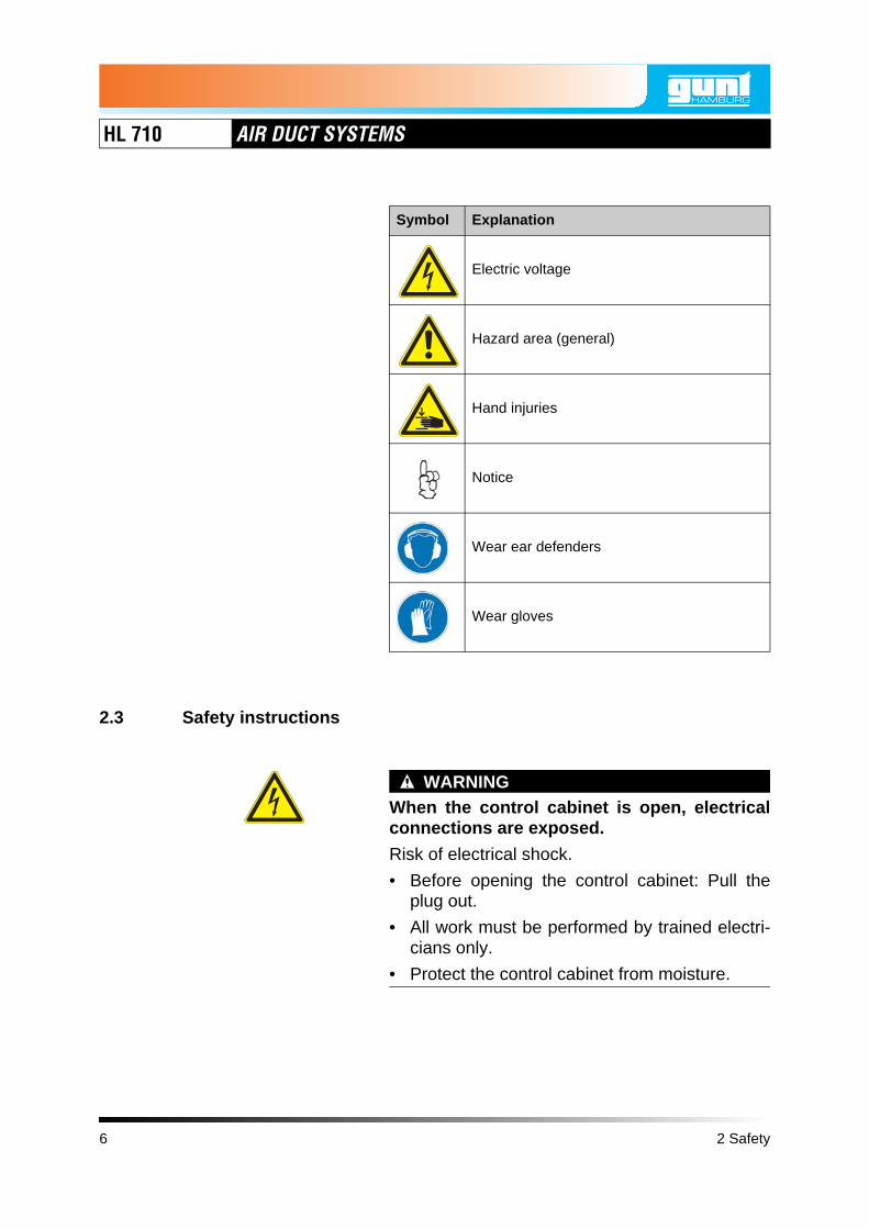
3.1.3 Assembly stand
The air ducts are held by assembly stands.These can be positioned according to the struc-ture of the air duct.
Each assembly stand consists of a stable baseframe, on which a vertical mounting bar isscrewed. Three height adjustable jibs areattached to the mounting bar.
The pipes are placed in rubber pipe clamps, whichare screwed hanging onto the jibs using threadedrods.
The assembly stands can be connected andsecured to each other with additional bars. Thus,stable air duct systems up to about 10m long canbe constructed.
3.1.4 Pipes and adapter pieces
The pipes are up to 1,6m long spiral seam ductswith the nominal diameters DN 100 and DN 200.The outer spiral folded seam provides the rigidityrequired by the thin-walled pipes. The pipes aremade of galvanized sheet metal.
Fig. 3.3 Assembly stand
Pipe clampThreaded rod
Base frame
Mounting bar
Jib
Fig. 3.4 Spiral seam duct
12 3 Description of the system

HL 710 AIR DUCT SYSTEMS
All
right
s re
serv
ed, G
.U.N
.T. G
erät
ebau
, Bar
sbüt
tel,
Ger
man
y 01
/201
1
The pipes are connected together with plug con-nectors. A plug connector is plugged into theends of the pipes to be connected, i.e. the plugconnector sits inside. The joints are then sealedwith adhesive tape.
Sleeves are needed to connect different shapedpieces with each other. They are stuck on theends of the respective elements to be connected,so that the sleeve is sitting on the outside.
Reducers connect pipes and other componentsof different nominal diameters.
Fig. 3.5 Plug connector
Fig. 3.6 Sleeve
Fig. 3.7 Reducer
3 Description of the system 13

HL 710 AIR DUCT SYSTEMS
3.1.5 Bends and branches
Installing bends makes it possible to change thedirection within the air duct system.
Branched air duct systems can be built usingbranches.
45° branches are suited to the flow of air ducts.Just by looking it is obvious that the flow is betterthan in 90° branches.
A variant of the branch is the branch withreducer. This branches off from a large nominaldiameter directly into a smaller nominal diameter.
Fig. 3.8 90° bend and 45° bend
Fig. 3.9 45° branch and 90° branch
Fig. 3.10 90° branch with reducer
14 3 Description of the system
HL 710 AIR DUCT SYSTEMS
All
right
s re
serv
ed, G
.U.N
.T. G
erät
ebau
, Bar
sbüt
tel,
Ger
man
y 01
/201
1
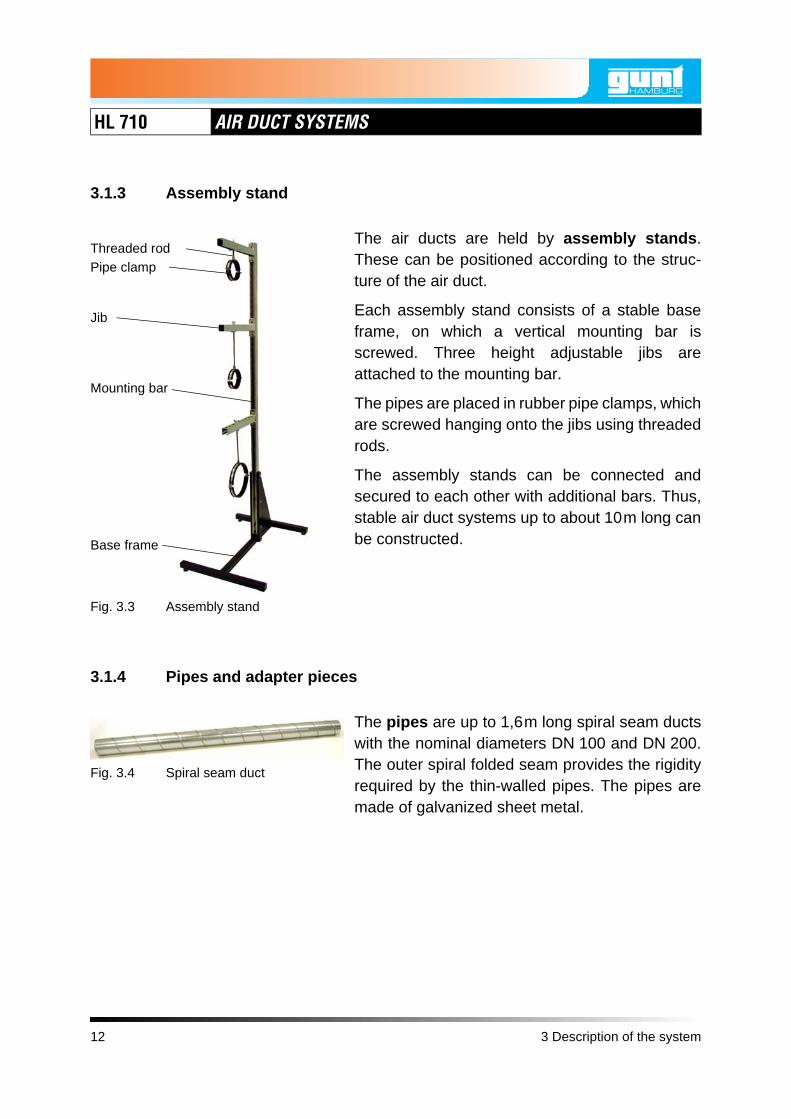
3.1.6 Throttle valve and iris
The air flow can be throttled by flaps and aper-tures.
The throttle valve can be adjusted with a handle.Various lockable positions are possible, thismeans
• Position 0: Closed
In this case, however, a small permeable annu-lar gap remains between valve and pipe wall,so that the pipe is not blocked completely.
• Position 9: Open
The iris can be moved into various positionsusing a knob that snaps into place, this means
• Position 1: Closed
• Position 6: Open
The iris does not close completely. Approxi-mately 34% of the pipe cross-section remainsopen.
Pressure measure points for static pressure arelocated directly in front of and behind the iris.
Fig. 3.11 Throttle valve
Fig. 3.12 Iris with pressure measuring points
3 Description of the system 15

HL 710 AIR DUCT SYSTEMS
3.1.7 Pressure measuring points
To take pressure measurements, a large numberof short pipes with pressure measurementpoints are provided. They are designed so thatthey can be used in various parts of the air ductsystem.
The pressure measuring points consist of:
• a static probe to measure the static pressure
• or a pitot tube to measure the total pressure.
All pressure measuring points have a nozzle or asmall tube, to which a PVC tube is connected,which connects the measuring point with the pres-sure gauge.
Depending on the arrangement of the pressuremeasuring points, pressure gradients are meas-ured in the air duct system and pressure drops inindividual components.
Fig. 3.13 Pressure measuring points
Static probe
Pitot tube
16 3 Description of the system

HL 710 AIR DUCT SYSTEMS
All
right
s re
serv
ed, G
.U.N
.T. G
erät
ebau
, Bar
sbüt
tel,
Ger
man
y 01
/201
1
3.1.8 Filters and outlets
Filters separate out liquid or solid particles fromthe air. The filter elements used here (filter mat-ting and pocket filters) are used frequently in prac-tice as pre-filters.
For training purposes, the filter elements of theHL 710 air duct system can be operated with andwithout filter elements.
Outlets distribute the air in the ventilated room.
Linear diffusers have shutters and valves to con-trol the direction and intensity of the outgoing airflow. Here, the flow behaviour can be observed atdifferent positions.
Linear diffusers should be adjusted in actual useso that people are not bothered by excessivedraught.
Fig. 3.14 Filter cartridges
Filter cartridge for filter matting
Filter cartridge for pocket filter
Fig. 3.15 Linear diffuser
3 Description of the system 17
HL 710 AIR DUCT SYSTEMS
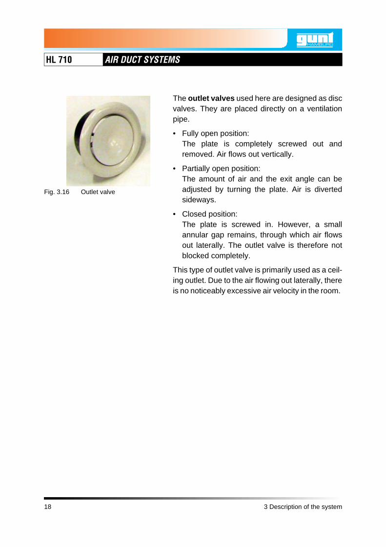
The outlet valves used here are designed as discvalves. They are placed directly on a ventilationpipe.
• Fully open position: The plate is completely screwed out andremoved. Air flows out vertically.
• Partially open position: The amount of air and the exit angle can beadjusted by turning the plate. Air is divertedsideways.
• Closed position: The plate is screwed in. However, a smallannular gap remains, through which air flowsout laterally. The outlet valve is therefore notblocked completely.
This type of outlet valve is primarily used as a ceil-ing outlet. Due to the air flowing out laterally, thereis no noticeably excessive air velocity in the room.
Fig. 3.16 Outlet valve
18 3 Description of the system

HL 710 AIR DUCT SYSTEMS
All
right
s re
serv
ed, G
.U.N
.T. G
erät
ebau
, Bar
sbüt
tel,
Ger
man
y 01
/201
1
3.1.9 Manometer
There should be at least 1m calmed distancebefore a pressure measuring point, in order toreduce measurement errors caused by turbu-lence.
Small pressure changes are measured with theinclined tube manometer.
Before using the inclined tube manometer, carryout the following steps in accordance with themanufacturer's instructions for the inclined tubemanometer:
1. Align the inclined tube manometer horizontally.
2. Fill the inclined tube manometer with themanometer liquid.
3. Adjust the zero point.
The digital manometer is suitable for a largepressure range.
Details on operation are contained in the manu-facturer's instructions for the digital manometer.
Fig. 3.17 Inclined tube manometer
Fig. 3.18 Digital manometer
3 Description of the system 19

HL 710 AIR DUCT SYSTEMS
3.1.10 Anemometer
The anemometer is used to measure the flowvelocity and the volume flow.
With the vane anemometer used here, there is avane in the anemometer housing, which is set inrotation during inflow. The rotational speed is con-verted into flow velocity in the unit; this will then beshown on the display.
To measure volume flow rates, a volume flowhood is also used.
Details on operation are contained in the manu-facturer's instructions for the anemometer.
Fig. 3.19 Anemometer with volume flow hood
20 3 Description of the system

HL 710 AIR DUCT SYSTEMS
All
right
s re
serv
ed, G
.U.N
.T. G
erät
ebau
, Bar
sbüt
tel,
Ger
man
y 01
/201
1
3.2 Operation
3.2.1 Positioning and connection
1. Ensure that there is sufficient space available.
The maximum length of the air duct systemHL 710 is 11m. Allow additional space for unre-stricted inlet and outlet.
2. Lock the wheels of the frame on which the fanand the control cabinet are located.
3. Assemble the components to the desiredexperiment layout.
WARNINGSharp edges on the pipes.
Risk of hand injuries.
• Wear gloves.
4. Seal the joints with adhesive tape.
5. Connect the control cabinet to the power sup-ply.
3 Description of the system 21
HL 710 AIR DUCT SYSTEMS
3.2.2 Operation
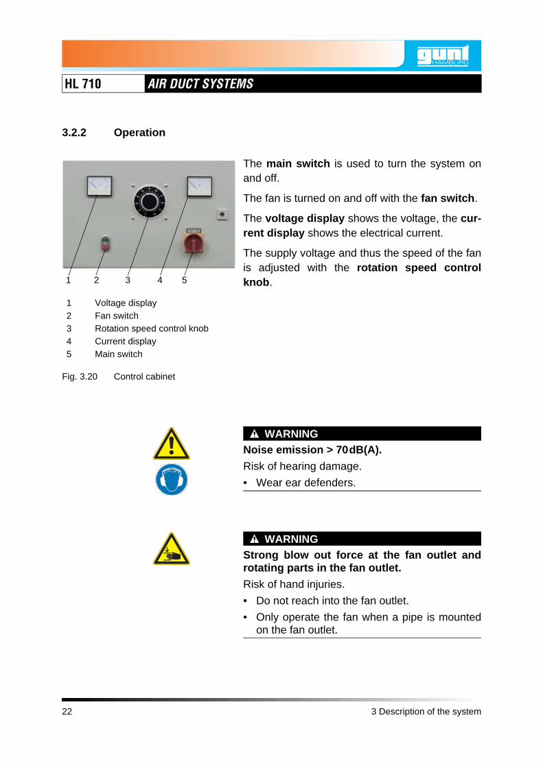
The main switch is used to turn the system onand off.
The fan is turned on and off with the fan switch.
The voltage display shows the voltage, the cur-rent display shows the electrical current.
The supply voltage and thus the speed of the fanis adjusted with the rotation speed controlknob.
WARNINGNoise emission > 70dB(A).
Risk of hearing damage.
• Wear ear defenders.
WARNINGStrong blow out force at the fan outlet androtating parts in the fan outlet.
Risk of hand injuries.
• Do not reach into the fan outlet.
• Only operate the fan when a pipe is mountedon the fan outlet.
Fig. 3.20 Control cabinet
1 Voltage display2 Fan switch3 Rotation speed control knob4 Current display5 Main switch
1 2 3 4 5
22 3 Description of the system

HL 710 AIR DUCT SYSTEMS
All
right
s re
serv
ed, G
.U.N
.T. G
erät
ebau
, Bar
sbüt
tel,
Ger
man
y 01
/201
1
CAUTIONStrong suction force at the fan inlet.
Items and clothing may be drawn in.
• Do not stand near the fan inlet.
• Do not store loose items where they can bedrawn in by the fan.
NOTICEOverload of the electrics.
Risk of damage to the electrics.
• Ensure that the following currents are compliedwith during continuous load:120V: max 12,5A230V: max 6A
3.2.3 Measuring pressures and differential pressures
Pressures and differential pressures at pressuremeasuring points can be measured both with theinclined tube manometer and with the digitalmanometer. Details on operation are containedin the respective manufacturer's instructions.
3 Description of the system 23

HL 710 AIR DUCT SYSTEMS
• Measure pressure relative to atmosphericpressure:
– Connect the connector indicated with "+" onthe pressure gauge with a hose to a meas-urement point for static pressure.
– The connector on the manometer markedwith "-" remains free.
• Measure differential pressure:
– Connect the connector indicated with "+" onthe pressure gauge with a hose to the firstmeasurement point for static pressure.
The pressure at the first measuring pointmust be greater than the pressure at thesecond measuring point.
– Connect the connector indicated with "-" onthe pressure gauge with a hose to the sec-ond measuring point for static pressure.
Fig. 3.21 Measuring the pressure relative to the atmospheric pressure
+-
Fig. 3.22 Measuring the differential pressure with the digital manometer
+-
24 3 Description of the system

HL 710 AIR DUCT SYSTEMS
All
right
s re
serv
ed, G
.U.N
.T. G
erät
ebau
, Bar
sbüt
tel,
Ger
man
y 01
/201
1
• Measure dynamic pressure:
– Connect the connector indicated with "+" onthe pressure gauge with a hose to the meas-uring point for total pressure.
– Connect the connector indicated with "-" onthe pressure gauge with a hose to the meas-uring point for static pressure.
3.2.4 Measuring volume velocities and volume flows
Volume velocities and volume flows at pipe out-lets are measured with the anemometer. Detailson operation are contained in the manufacturer'sinstructions for the anemometer.
To measure volume flow rates, a volume flowhood is also used.
3.2.5 Maintenance
The HL 710 air duct system does not requiremaintenance.
See also the manufacturer's instructions of thecomponents.
Fig. 3.23 Measuring dynamic pressure with the digital manometer
+-
3 Description of the system 25

HL 710 AIR DUCT SYSTEMS
26 3 Description of the system

HL 710 AIR DUCT SYSTEMS
All
right
s re
serv
ed, G
.U.N
.T. G
erät
ebau
, Bar
sbüt
tel,
Ger
man
y 01
/201
1
4 Basic principles
The basic principles set out in the following makeno claim to completeness. For further theoreticalexplanations, refer to the specialist literature.
Knowledge of ventilation technology is a pre-requisite for the experiments with the HL 710 airduct system, see also G.U.N.T. document"Fundamental Principles of Air Conditioning Tech-nology".
4.1 Pressure, flow velocity and volume flow
The total pressure ptotal in a pipe consists of
• the static pressure pstat, that corresponds tothe air pressure in the pipe, and
• the dynamic pressure pdyn, which is generatedby the flowing air.
The total pressure ptotal is measured with a pitottube. It is located in the middle of the pipe and hasan opening at the stagnation point.
The static pressure pstat is measured at an open-ing with a static probe on the pipe wall.
The dynamic pressure can be calculated fromthe total pressure and the static pressure:
(4.1)Fig. 4.1 Measuring the total pressure and static pressure
pstat
ptotal
pdyn
Static probe
Pitot tube
pdyn ptotal pstat–=
4 Basic principles 27

HL 710 AIR DUCT SYSTEMS
The flow velocity can be calculated from thedynamic pressure:
(4.2)
v Flow velocityDensity of the flow mediumAir: 1,225kg/m3 at 15°C
The volume flow is determined from cross-section area and flow velocity.
The volume flow within an air duct system isalmost constant. In pipes with a small cross-section, the flow velocity and thus the dynamicpressure are greater, in pipes with a larger cross-section the flow velocity and the dynamic pres-sure are less.
= constant (4.3)
Volume flowAD Cross-section area of the pipe
From Formula (4.2) and Formula (4.3) it thus fol-lows:
(4.4)
v2 pdyn⋅
ρ-------------------=
ρ
V· AD v⋅=
V·
V· AD2 pdyn⋅
ρ-------------------⋅=
28 4 Basic principles

HL 710 AIR DUCT SYSTEMS
All
right
s re
serv
ed, G
.U.N
.T. G
erät
ebau
, Bar
sbüt
tel,
Ger
man
y 01
/201
1
4.2 Pressure losses in pipes
Pressure losses arise in each pipe due to frictionbetween the wall of the pipe and the flowingmedium. Pressure losses due to friction areexpressed by the pipe friction factor .
Pressure losses are calculated according toFormula (4.5).
(4.5)
Differential pressurePipe friction factor
l Length of the piped Diameter of the pipe
The formula can be solved for the pipe friction fac-tor:
(4.6)
4.3 Pressure losses in piping elements
Pressure losses occur in piping elements such asbends, branches and valves, as the pipe ele-ments constitute obstacles to consistent pipeflow. They lead to turbulence and thus unevenflow through pipe cross sections.
The flow resistance R of the pipe elements isexpressed by the dimensionless resistancecoefficient .
λ
Δp λ l⋅2 d⋅----------- ρ v 2⋅ ⋅=
Δpλ
λ 2 Δp d⋅ ⋅ρ l v 2⋅ ⋅-----------------------=
ζ
4 Basic principles 29
HL 710 AIR DUCT SYSTEMS
Pressure losses are calculated as follows.
(4.7)
Resistance coefficient
Correspondingly, the resistance coefficient canbe determined according to Formula (4.8):
(4.8)
Δp ζ ρ v 2
2------⋅ ⋅=
ζ
ζ 2 Δ⋅ p
ρ v 2⋅---------------=
30 4 Basic principles

HL 710 AIR DUCT SYSTEMS
All
right
s re
serv
ed, G
.U.N
.T. G
erät
ebau
, Bar
sbüt
tel,
Ger
man
y 01
/201
1
4.4 Characteristic curves
4.4.1 Functionality of a radial fan
An air particle passes through the air inlet (1) inthe centre of the impeller (2). Kinetic energy isgiven to the particle by it being entrained by theimpeller. Due to the centrifugal forces generatedby the circular motion, the particle leaves theimpeller and enters the spiral housing (3).
In the spiral housing, on the way to the air outlet(4), the particle is forced through the shape of thehousing. In this way the particle becomes sloweras the flow cross-section increases.
According to the law of continuity, therefore, thespeed decreases. According to the law of conser-vation of energy decreasing kinetic energy leadsto the increase in pressure energy.
The static pressure of the flowing medium isgreatest at the end of the spiral housing. It estab-lishes a steady state within the fan, with the higherpressure at the outlet and the lower pressure atthe inlet. This ensures the free inflow of air fromthe atmospheric environment.
Fig. 4.2 Air flow in a radial fan
1
1 Air inlet2 Impeller3 Spiral housing4 Air outlet
2
4
3
Air flow
Direction of rotation of the impeller
4 Basic principles 31

HL 710 AIR DUCT SYSTEMS
4.4.2 Fan characteristic curve
For a fan driven at a constant speed, the differen-tial pressure depends on the volume flow. Thisrelationship is shown in characteristic curves. Fancharacteristic curves are like the fan's "fingerprint"and are therefore an important tool for designinga system.
Fan characteristic curves show the volume flowsat different differential pressures. Each differentialpressure value refers to a certain volume flow(see Fig. 4.3).
When recording a fan's characteristic curve, thefan's speed of rotation is not changed. The vol-ume flow is varied by changing the flow resistanceR and thus the resistance coefficient , e.g. byusing a throttle valve.
The fan characteristic curve for HL 710 is shownin Chapter 7.2, Page 175.
ζ
32 4 Basic principles

HL 710 AIR DUCT SYSTEMS
All
right
s re
serv
ed, G
.U.N
.T. G
erät
ebau
, Bar
sbüt
tel,
Ger
man
y 01
/201
1
Altering the speed (see Fig. 4.3) alters the curve.Higher speeds cause greater differential pres-sures compared to low speeds.
Due to the different speeds, the air particlesentrained in the impeller are each given differentkinetic energies. The subsequent decrease in thekinetic energies due to the increasing flow cross-section in the spiral housing of the fan causes thepressure energy to increases as a function of thespeed.
Fig. 4.3 Fan characteristic curves with different speeds n1 and n2
Volume flow V·
Diff
eren
tial p
ress
ure Δ
p
n1
n2
n1 > n2
4 Basic principles 33

HL 710 AIR DUCT SYSTEMS
4.4.3 System characteristic curve
The system characteristic curve shows the pres-sure drop (differential pressure) , caused by allthe flow resistances R of the air duct to the fanoutlet, as a function of the volume flow .
Different system characteristic curves arise whenthe flow resistance is altered, for example byopening or closing a valve.
When recording a system curve, the volume flow will be altered by the change in speed n. In
doing so the internal components may not bemodified, because this would amount to a changein the flow resistance R, and thus the resistancecoefficients .
• The system characteristic curve shows the vol-ume flows at different pressures p.
• Each pressure value prefers to a certain vol-ume flow .
• The differential pressure is dependent onthe fan speed n.
• The differential pressure is proportional tothe square of the volume flow .
Δp
V·
V·
ζ
V·
V·
Δp
ΔpV·
34 4 Basic principles

HL 710 AIR DUCT SYSTEMS
All
right
s re
serv
ed, G
.U.N
.T. G
erät
ebau
, Bar
sbüt
tel,
Ger
man
y 01
/201
1
Fig. 4.4 System characteristic curve at constant flow resistance R
Volume flow V·
Diff
eren
tial p
ress
ure Δ
p
n1
n2
R = constantn1 > n2 > n3
n3
Fig. 4.5 System characteristic curve at different flow resistance R
Volume flow V·
Diff
eren
tial p
ress
ure Δ
p
R1
R2
R1 > R2 > R3
R3
4 Basic principles 35

HL 710 AIR DUCT SYSTEMS
4.4.4 Operating point
The operating point of a fan appears at the pointwhere the differential pressures of fan and systemare equal size, thus at the intercept point of thesystem curve and the fan curve (see Fig. 4.6).
The position of the operating point can bealtered
• via the fan speed n (see Fig. 4.7),
• or via the flow resistance R (see Fig. 4.8), forexample by changing the throttle valve posi-tion.
Fig. 4.6 Operating point
Volume flow V·
Diff
eren
tial p
ress
ure Δ
p
Operating point
System characteristic curve
Fan characteristic curve
36 4 Basic principles

HL 710 AIR DUCT SYSTEMS
All
right
s re
serv
ed, G
.U.N
.T. G
erät
ebau
, Bar
sbüt
tel,
Ger
man
y 01
/201
1
Fig. 4.7 Changing the operating point via the speed n
Volume flow V·
Diff
eren
tial p
ress
ure Δ
p
Operating point at n1
Operating point at n2
Fig. 4.8 Changing the operating point via the flow resistance R
Volume flow V·
Diff
eren
tial p
ress
ure Δ
p
Operating point at R1
Operating point at R2
R1 R2
4 Basic principles 37
HL 710 AIR DUCT SYSTEMS
4.4.5 Efficiency
To determine the volume flow that is drawn in, thetotal pressure ptotal and static pressure pstat aremeasured after the inflow into the intake port.From this we can calculate:
• the dynamic pressure pdyn see Formula (4.1), Page 27
• the flow velocity vsee Formula (4.2), Page 28
• the volume flow see Formula (4.3), Page 28.
To determine the supply pressure, the pressuredifference between the static pressure ps at thesuction side of the fan and the static pressure ppat the pressure side of the fan is measured.
(4.9)
ps Pressure at the suction side of thefan
pp Pressure at the pressure side of thefan
The delivered hydraulic power (capacity) canbe calculated from the volume flow and the totalpressure increase (consisting of static anddynamic portions). Generally, the dynamic portionis considered if the speeds in the suction-sidecross-section As and in the pressure-side cross-section Ap are of different sizes. This is the casewhen the cross-section areas As and Ap are differ-ent sizes.
V·
Δp ps pp–=
38 4 Basic principles

HL 710 AIR DUCT SYSTEMS
All
right
s re
serv
ed, G
.U.N
.T. G
erät
ebau
, Bar
sbüt
tel,
Ger
man
y 01
/201
1
(4.10)
(4.11)
Phydr Hydraulic powerpp Pressure at the pressure side of the
fanps Pressure at the suction side of the
fan
The supplied electrical power is calculated asfollows:
(4.12)
Pel Electrical powerU VoltageI Current
The fan efficiency is obtained from the ratio ofthe delivered hydraulic power to the suppliedelectrical power.
(4.13)
Phydr V· p⋅=
Phydr V· pp ps–( ) ρ2--- vp
2 vs2
–( )⋅+⋅=
Pel U I⋅=
η
ηPhydr
Pel-------------=
4 Basic principles 39

HL 710 AIR DUCT SYSTEMS
40 4 Basic principles

HL 710 AIR DUCT SYSTEMS
All
right
s re
serv
ed, G
.U.N
.T. G
erät
ebau
, Bar
sbüt
tel,
Ger
man
y 01
/201
1
5 Tasks
Tasks
Worksheet A – Components of the air duct system Page 42
Worksheet B – Assembling a complex air duct system Page 45
Worksheet C – Two methods for determining the dynamic pressure Page 52
Worksheet D – Two methods for determining the flow velocity Page 57
Worksheet E – Two methods for determining the volume flow Page 64
Worksheet F – Pressure loss and resistance coefficient of a composite 180° bend
Page 72
Worksheet G – Characteristic curve of the pressure loss over a 90° bend Page 77
Worksheet H – Characteristic curve of the pressure loss over a filter Page 83
Worksheet I – Characteristic curve of the lower pipeline Page 89
Worksheet J – Throttle characteristic curve of the lower pipeline Page 95
Worksheet K – Air distribution in the air duct system Page 101
5 Tasks 41

HL 710 AIR DUCT SYSTEMS
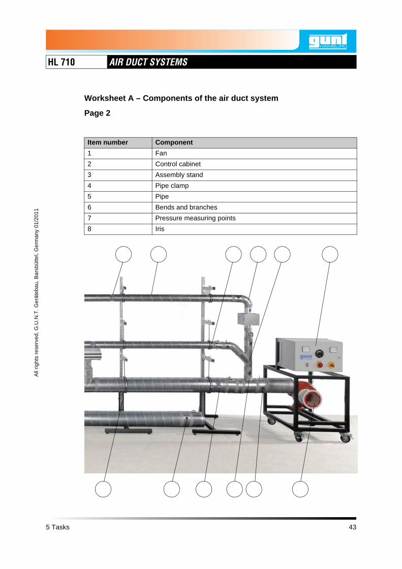
5.1 Worksheet A – Components of the air duct system
Page 1
Objective
To recognise and name the components of an air duct system
Exercise
1. On the following page you will see a section of an air duct system.
Enter the item numbers of the components from the table in the image.
42 5 Tasks
HL 710 AIR DUCT SYSTEMS
All
right
s re
serv
ed, G
.U.N
.T. G
erät
ebau
, Bar
sbüt
tel,
Ger
man
y 01
/201
1
Worksheet A – Components of the air duct system
Page 2
Item number Component
1 Fan
2 Control cabinet
3 Assembly stand
4 Pipe clamp
5 Pipe
6 Bends and branches
7 Pressure measuring points
8 Iris
5 Tasks 43

HL 710 AIR DUCT SYSTEMS
Worksheet A – Components of the air duct system
Page 3
2. Here you can see some components that can be fitted to the air duct.
Enter the names of the components in table.
Item 1 Item 2 Item 3
Item 8Item 5 Item 6 Item 7
Item 4
Item number Component
1
2
3
4
5
6
7
8
44 5 Tasks

HL 710 AIR DUCT SYSTEMS
All
right
s re
serv
ed, G
.U.N
.T. G
erät
ebau
, Bar
sbüt
tel,
Ger
man
y 01
/201
1
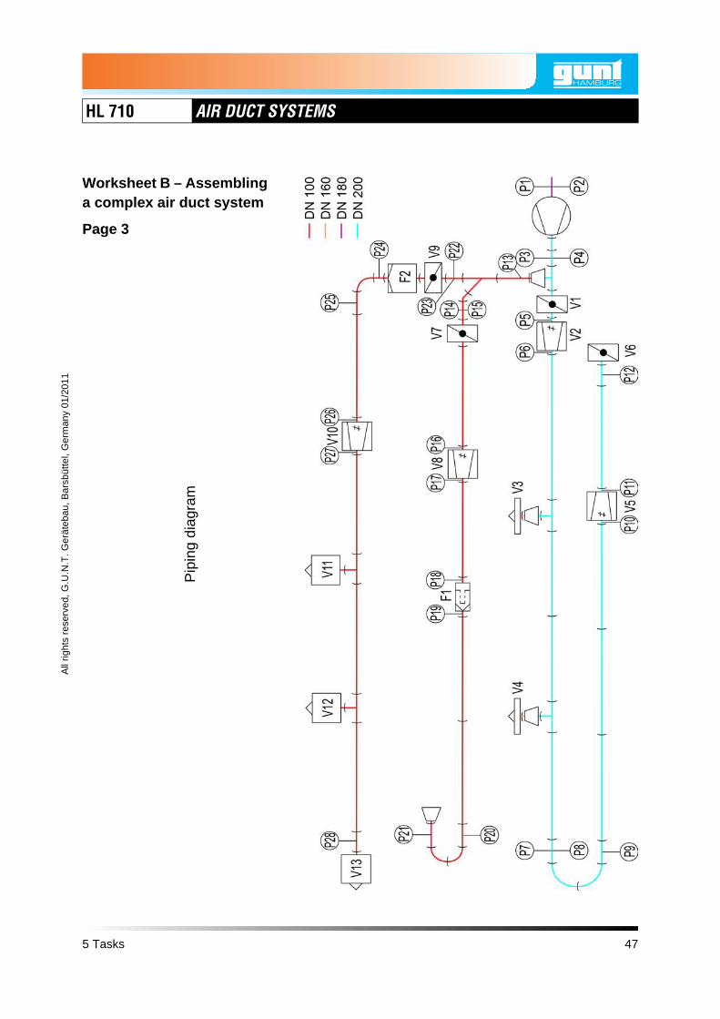
5.2 Worksheet B – Assembling a complex air duct system
Page 1
Objective
• To assemble an air duct system
• To recognise possible pressure measurements
Exercise
On the following pages you will see a complex air duct system, representedas
• Illustration
• Piping diagram
• Parts list
• List of measuring points.
5 Tasks 45

HL 710 AIR DUCT SYSTEMS
Illus
trat
ion
Worksheet B – Assembling a complex air duct system
Page 2
46 5 Tasks
HL 710 AIR DUCT SYSTEMS
All
right
s re
serv
ed, G
.U.N
.T. G
erät
ebau
, Bar
sbüt
tel,
Ger
man
y 01
/201
1
Pip
ing
diag
ram
Worksheet B – Assembling a complex air duct system
Page 3
5 Tasks 47

HL 710 AIR DUCT SYSTEMS
Worksheet B – Assembling a complex air duct system
Page 4
Parts list, part 1
Symbol Name Nominal diameter
Quan-tity
Identifi-cation letter
Fan 1
Assembly stand 5
Pipe, length 1600mmDN 100 8
DN 200 8
Sleeve
DN 100 5
DN 160 2
DN 200 5
Plug connectorDN 100 4
DN 200 7
45° bend DN 100 1
90° bendDN 100 3
DN 200 2
45° branch DN 100 1
90° branchDN 100 2
DN 200 2
90° branch with reducerDN 200 - DN 100
1
48 5 Tasks

HL 710 AIR DUCT SYSTEMS
All
right
s re
serv
ed, G
.U.N
.T. G
erät
ebau
, Bar
sbüt
tel,
Ger
man
y 01
/201
1
Worksheet B – Assembling a complex air duct system
Page 5
Parts list, part 2
Symbol Name Nominal diameter
Quan-tity
Identifi-cation letter
Reducer
DN 200 - DN 160
2
DN 160 - DN 100
1
Throttle valveDN 100 2 V7, V9
DN 200 2 V1, V6
IrisDN 100 2 V8, V10
DN 200 2 V2, V5
Pipe with measuring point for static pressure
DN 100 6
DN 200 2
Pipe with measuring point for static pressure and measuring point for total pressure
DN 100 2
DN 180 1
DN 200 2
Pocket filter DN 100 1 F1
Filter (filter matting) DN 100 1 F2
Linear diffuser DN 160 2 V3, V4
Outlet valve DN 100 3V11, V12, V13
Adhesive tape
5 Tasks 49

HL 710 AIR DUCT SYSTEMS
Worksheet B – Assembling a complex air duct system
Page 6
List of measuring points
Type of measuring point
Measuring point identification letter
Nominal diameter of
the pipe
Cross-section area of the pipe
Measuring point for static pressure
P13, P14, P16, P17, P18, P19, P20, P21, P22, P24, P25, P26, P27, P28
DN 100 7.854mm2
P1 DN 180 25.447mm2
P3, P5, P6, P7, P9, P10, P11, P12
DN 200 31.416mm2
Measuring point for total pressure
P15, P23 DN 100 7.854mm2
P2 DN 180 25.447mm2
P4, P8 DN 200 31.416mm2
50 5 Tasks

HL 710 AIR DUCT SYSTEMS
All
right
s re
serv
ed, G
.U.N
.T. G
erät
ebau
, Bar
sbüt
tel,
Ger
man
y 01
/201
1
Worksheet B – Assembling a complex air duct system
Page 7
1. Assemble the system shown from the components of the HL 710 air ductsystem and tightly seal the joints with tape.
CAUTIONSharp edges on the pipes.
Risk of hand injuries.
• Wear gloves.
This experiment layout is the basis for the worksheets in Chapter 5.3,Page 52, to Chapter 5.11, Page 101.
2. Pressure measurement points are shown in the piping diagram onPage 47.
Which pressure measurements could you perform on this system? Namethe measuring points and the purpose of each measurement.
Pressure measuring points
Purpose of the measurement
Example: P3 and P12 Pressure drop across the lower pipeline at different volume flows.
5 Tasks 51

HL 710 AIR DUCT SYSTEMS
5.3 Worksheet C – Two methods for determining the dynamic pressure
Page 1
Objective
• To measure dynamic pressure as differential pressure
• To measure total pressure and static pressure and to calculate thedynamic pressure
• To compare results of both methods
• Familiarisation with the digital manometer
Measuring equipment
• Digital manometer
52 5 Tasks
HL 710 AIR DUCT SYSTEMS
All
right
s re
serv
ed, G
.U.N
.T. G
erät
ebau
, Bar
sbüt
tel,
Ger
man
y 01
/201
1
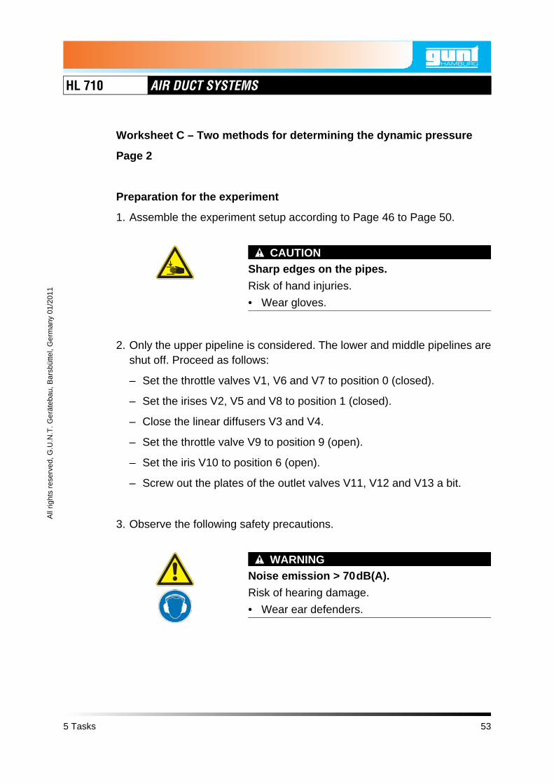
Worksheet C – Two methods for determining the dynamic pressure
Page 2
Preparation for the experiment
1. Assemble the experiment setup according to Page 46 to Page 50.
CAUTIONSharp edges on the pipes.
Risk of hand injuries.
• Wear gloves.
2. Only the upper pipeline is considered. The lower and middle pipelines areshut off. Proceed as follows:
– Set the throttle valves V1, V6 and V7 to position 0 (closed).
– Set the irises V2, V5 and V8 to position 1 (closed).
– Close the linear diffusers V3 and V4.
– Set the throttle valve V9 to position 9 (open).
– Set the iris V10 to position 6 (open).
– Screw out the plates of the outlet valves V11, V12 and V13 a bit.
3. Observe the following safety precautions.
WARNINGNoise emission > 70dB(A).
Risk of hearing damage.
• Wear ear defenders.
5 Tasks 53

HL 710 AIR DUCT SYSTEMS
Worksheet C – Two methods for determining the dynamic pressure
Page 3
WARNINGStrong blow out force at the fan outlet androtating parts in the fan outlet.
Risk of hand injuries.
• Do not reach into the fan outlet.
• Only operate the fan when a pipe is mountedon the fan outlet.
CAUTIONStrong suction force at the fan inlet.
Items and clothing may be drawn in.
• Do not stand near the fan inlet.
• Do not store loose items where they can bedrawn in by the fan.
NOTICEOverload of the electrics.
Risk of damage to the electrics.
• Ensure that the following currents are compliedwith during continuous load:120V: max 12,5A230V: max 6A
4. Turn the main switch on.
5. Turn the fan switch on.
6. Turn the rotation speed control knob to 100%.
54 5 Tasks

HL 710 AIR DUCT SYSTEMS
All
right
s re
serv
ed, G
.U.N
.T. G
erät
ebau
, Bar
sbüt
tel,
Ger
man
y 01
/201
1
Worksheet C – Two methods for determining the dynamic pressure
Page 4
Exercise
1. Measuring dynamic pressure as differential pressure
• Use the digital manometer to measure the differential pressure betweenmeasuring point P22 and measuring point P23.
This differential pressure corresponds to the dynamic pressure pdyn1.
• Note down the measurement result:
Measuring points 22 and 23
Dynamic pressure pdyn1in Pa
P22
P23
5 Tasks 55

HL 710 AIR DUCT SYSTEMS
Worksheet C – Two methods for determining the dynamic pressure
Page 5
2. Measuring total pressure and static pressure and from this calculating thedynamic pressure
• Use the digital manometer to measure the total pressure at measuringpoint P23 and note down the measured value in the table below.
• Use the digital manometer to measure the static pressure at measuringpoint P22 and note down the measured value.
• Calculate the difference between total pressure and static pressure.This is the dynamic pressure pdyn2.
Measurements:
3. Comparing both dynamic pressures
Compare the dynamic pressure pdyn1 from task 1 with the dynamic pres-sure pdyn2 from task 2.
Measuring point 23 Measuring point 22 Measuring points 22 and 23
Total pressure ptotal in Pa
Static pressure pstat in Pa
Dynamic pressure pdyn2 in Pa
56 5 Tasks

HL 710 AIR DUCT SYSTEMS
All
right
s re
serv
ed, G
.U.N
.T. G
erät
ebau
, Bar
sbüt
tel,
Ger
man
y 01
/201
1
5.4 Worksheet D – Two methods for determining the flow velocity
Page 1
Objective
• Familiarisation with measuring the flow velocity
• Familiarisation with measuring dynamic pressure as differential pressure
• To calculate the flow velocity from the dynamic pressure
• To compare measured and calculated flow velocities
• Familiarisation with the anemometer
Measuring equipment
• Digital manometer
• Anemometer
5 Tasks 57
HL 710 AIR DUCT SYSTEMS
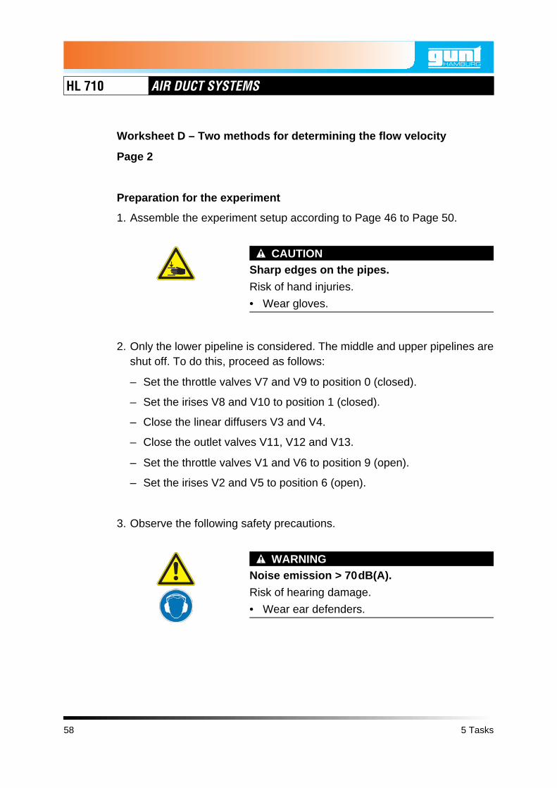
Worksheet D – Two methods for determining the flow velocity
Page 2
Preparation for the experiment
1. Assemble the experiment setup according to Page 46 to Page 50.
CAUTIONSharp edges on the pipes.
Risk of hand injuries.
• Wear gloves.
2. Only the lower pipeline is considered. The middle and upper pipelines areshut off. To do this, proceed as follows:
– Set the throttle valves V7 and V9 to position 0 (closed).
– Set the irises V8 and V10 to position 1 (closed).
– Close the linear diffusers V3 and V4.
– Close the outlet valves V11, V12 and V13.
– Set the throttle valves V1 and V6 to position 9 (open).
– Set the irises V2 and V5 to position 6 (open).
3. Observe the following safety precautions.
WARNINGNoise emission > 70dB(A).
Risk of hearing damage.
• Wear ear defenders.
58 5 Tasks

HL 710 AIR DUCT SYSTEMS
All
right
s re
serv
ed, G
.U.N
.T. G
erät
ebau
, Bar
sbüt
tel,
Ger
man
y 01
/201
1
Worksheet D – Two methods for determining the flow velocity
Page 3
WARNINGStrong blow out force at the fan outlet androtating parts in the fan outlet.
Risk of hand injuries.
• Do not reach into the fan outlet.
• Only operate the fan when a pipe is mountedon the fan outlet.
CAUTIONStrong suction force at the fan inlet.
Items and clothing may be drawn in.
• Do not stand near the fan inlet.
• Do not store loose items where they can bedrawn in by the fan.
NOTICEOverload of the electrics.
Risk of damage to the electrics.
• Ensure that the following currents are compliedwith during continuous load:120V: max 12,5A230V: max 6A
4. Turn the main switch on.
5. Turn the fan switch on.
5 Tasks 59

HL 710 AIR DUCT SYSTEMS
Worksheet D – Two methods for determining the flow velocity
Page 4
Exercise
1. Taking measurements
Set the rotation speed control knob to 100% and take the following meas-urements:
• Use the digital manometer to measure the differential pressure betweenmeasuring points P7 and P8. This is the dynamic pressure at measuringpoint P8. Note down the value in the table on the next page.
• Use the anemometer to measure the flow velocity at the outlet of thelower pipeline. Note down the value in the table.
Gradually reduce the position of the rotation speed control knob andrepeat the measurements. Note down your measurement results in thetable on the following page.
P8 P7
Outlet of the lower pipeline
60 5 Tasks

HL 710 AIR DUCT SYSTEMS
All
right
s re
serv
ed, G
.U.N
.T. G
erät
ebau
, Bar
sbüt
tel,
Ger
man
y 01
/201
1
Worksheet D – Two methods for determining the flow velocity
Page 5
2. Calculation
Calculate the flow velocities from the dynamic pressures at measuringpoint P8 and enter the results in the table.
Rotation speed control knob
Measuring point P8 Outlet of the lower pipeline
in % Dynamic pressure pP8
in Pa
Flow velocity calculated
in m/s
Flow velocity measured
in m/s
v v
5 Tasks 61

HL 710 AIR DUCT SYSTEMS
Worksheet D – Two methods for determining the flow velocity
Page 6
3. Comparison
Compare the measured and calculated flow velocities and evaluate the dif-ferences.
62 5 Tasks

HL 710 AIR DUCT SYSTEMS
All
right
s re
serv
ed, G
.U.N
.T. G
erät
ebau
, Bar
sbüt
tel,
Ger
man
y 01
/201
1
Worksheet D – Two methods for determining the flow velocity
Page 7
4. Improving the measurements
With which measurements at the measuring points P8 and at the outlet ofthe lower pipeline could you achieve better results?
5 Tasks 63

HL 710 AIR DUCT SYSTEMS
5.5 Worksheet E – Two methods for determining the volume flow
Page 1
Objective
• Familiarisation with the volume flow at outlet valves
• Familiarisation with measuring dynamic pressure as differential pressure
• To calculate the volume flow from the dynamic pressure
• To compare measured and calculated volume flows
Measuring equipment
• Digital manometer
• Anemometer
Preparation for the experiment
1. Assemble the experiment setup according to Page 46 to Page 50.
CAUTIONSharp edges on the pipes.
Risk of hand injuries.
• Wear gloves.
2. Only the upper pipeline is considered. The lower and middle pipelines areshut off. Proceed as follows:
– Set the throttle valves V1, V6 and V7 to position 0 (closed).
– Set the irises V2, V5 and V8 to position 1 (closed).
– Close the linear diffusers V3 and V4.
– Set the throttle valve V9 to position 9 (open).
– Set the iris V10 to position 6 (open).
64 5 Tasks

HL 710 AIR DUCT SYSTEMS
All
right
s re
serv
ed, G
.U.N
.T. G
erät
ebau
, Bar
sbüt
tel,
Ger
man
y 01
/201
1
Worksheet E – Two methods for determining the volume flow
Page 2
3. Observe the following safety precautions.
WARNINGNoise emission > 70dB(A).
Risk of hearing damage.
• Wear ear defenders.
WARNINGStrong blow out force at the fan outlet androtating parts in the fan outlet.
Risk of hand injuries.
• Do not reach into the fan outlet.
• Only operate the fan when a pipe is mountedon the fan outlet.
CAUTIONStrong suction force at the fan inlet.
Items and clothing may be drawn in.
• Do not stand near the fan inlet.
• Do not store loose items where they can bedrawn in by the fan.
5 Tasks 65

HL 710 AIR DUCT SYSTEMS
Worksheet E – Two methods for determining the volume flow
Page 3
NOTICEOverload of the electrics.
Risk of damage to the electrics.
• Ensure that the following currents are compliedwith during continuous load:120V: max 12,5A230V: max 6A
4. Turn the main switch on.
5. Turn the fan switch on.
6. Set the rotation speed control knob to 100%.
66 5 Tasks

HL 710 AIR DUCT SYSTEMS
All
right
s re
serv
ed, G
.U.N
.T. G
erät
ebau
, Bar
sbüt
tel,
Ger
man
y 01
/201
1
Worksheet E – Two methods for determining the volume flow
Page 4
Exercise
1. Measuring flow rates at outlet valves
• Screw out the plates of the outlet valves V11, V12 and V13 all the way,so that all three outlet valves are open simultaneously.
• Use the anemometer and the volume flow hood to measure the volumeflow at the outlet valves V11, V12 and V13.
Note down the measurement results in the following table:
Outlet valve V11 Outlet valve V12 Outlet valve V13
Volume flow in ltr/s
Volume flow in ltr/s
Volume flow in ltr/s
V13 V12 V11
V· V11 V· V12 V· V13
5 Tasks 67

HL 710 AIR DUCT SYSTEMS
Worksheet E – Two methods for determining the volume flow
Page 5
• Screw the plates back into the outlet valves V11, V12 and V13.
• Turn the plates in or out until you are measuring the same volume flowat all three outlet valves.
Note down the measurement results as an aid:
Outlet valve V11 Outlet valve V12 Outlet valve V13
Volume flow in ltr/s
Volume flow in ltr/s
Volume flow in ltr/s
Adjusted, same volume flow at the exhaust valves V11, V12 and V13
Sum of the volume flow at the outlet valves V11, V12 and V13
V· V11 V· V12 V· V13
V· sum
68 5 Tasks

HL 710 AIR DUCT SYSTEMS
All
right
s re
serv
ed, G
.U.N
.T. G
erät
ebau
, Bar
sbüt
tel,
Ger
man
y 01
/201
1
Worksheet E – Two methods for determining the volume flow
Page 6
2. Measuring dynamic pressure
• Use the digital manometer to measure the differential pressure betweenmeasuring point P22 and measuring point P23.
This differential pressure corresponds to the dynamic pressure.
• Note down the measurement result in the table.
Measuring point 23
Dynamic pressure pdyn in Pa
P22
P23
5 Tasks 69

HL 710 AIR DUCT SYSTEMS
Worksheet E – Two methods for determining the volume flow
Page 7
3. Calculating volume flow
Calculate the volume flow from the dynamic pressure at the measuringpoint P23.
Your calculation result:
= V· calc
70 5 Tasks

HL 710 AIR DUCT SYSTEMS
All
right
s re
serv
ed, G
.U.N
.T. G
erät
ebau
, Bar
sbüt
tel,
Ger
man
y 01
/201
1
Worksheet E – Two methods for determining the volume flow
Page 8
4. Comparing measured and calculated volume flow
The volume flow you calculated in task 1 is:
The volume flow you measured in task 2 is:
Compare the two volume flows. Explain the different values.
How could you improve the measurement of the dynamic pressure to getbetter results for the calculated volume flow ?
V· sum
V· calc
V· calc
5 Tasks 71

HL 710 AIR DUCT SYSTEMS
5.6 Worksheet F – Pressure loss and resistance coefficient of a composite 180° bend
Page 1
Objective
• To measure the pressure loss of a composite 180° bend
• To calculate the resistance coefficient of the bend
• Familiarisation with an inclined tube manometer
Measuring equipment
• Inclined tube manometer
• Anemometer
Preparation for the experiment
1. Assemble the experiment setup according to Page 46 to Page 50.
CAUTIONSharp edges on the pipes.
Risk of hand injuries.
• Wear gloves.
2. Only the lower pipeline is considered. The middle and upper pipelines areshut off. To do this, proceed as follows:
– Set the throttle valves V7 and V9 to position 0 (closed).
– Set the irises V8 and V10 to position 1 (closed).
– Close the linear diffusers V3 and V4.
– Close the outlet valves V11, V12 and V13.
– Set the throttle valves V1 and V6 to position 9 (open).
– Set the irises V2 and V5 to position 6 (open).
72 5 Tasks

HL 710 AIR DUCT SYSTEMS
All
right
s re
serv
ed, G
.U.N
.T. G
erät
ebau
, Bar
sbüt
tel,
Ger
man
y 01
/201
1
Worksheet F – Pressure loss and resistance coefficient of a composite 180° bend
Page 2
3. Observe the following safety precautions.
WARNINGNoise emission > 70dB(A).
Risk of hearing damage.
• Wear ear defenders.
WARNINGStrong blow out force at the fan outlet androtating parts in the fan outlet.
Risk of hand injuries.
• Do not reach into the fan outlet.
• Only operate the fan when a pipe is mountedon the fan outlet.
CAUTIONStrong suction force at the fan inlet.
Items and clothing may be drawn in.
• Do not stand near the fan inlet.
• Do not store loose items where they can bedrawn in by the fan.
5 Tasks 73

HL 710 AIR DUCT SYSTEMS
Worksheet F – Pressure loss and resistance coefficient of a composite 180° bend
Page 3
NOTICEOverload of the electrics.
Risk of damage to the electrics.
• Ensure that the following currents are compliedwith during continuous load:120V: max 12,5A230V: max 6A
4. Turn the main switch on.
5. Turn the fan switch on.
74 5 Tasks
HL 710 AIR DUCT SYSTEMS
All
right
s re
serv
ed, G
.U.N
.T. G
erät
ebau
, Bar
sbüt
tel,
Ger
man
y 01
/201
1
Worksheet F – Pressure loss and resistance coefficient of a composite 180° bend
Page 4
Exercise
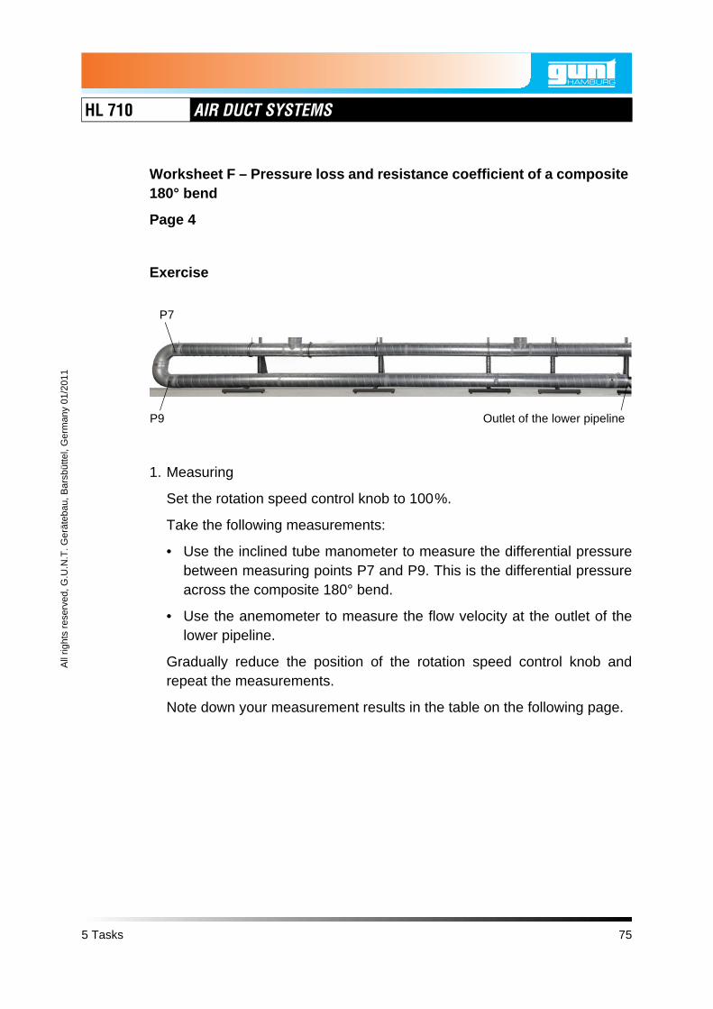
1. Measuring
Set the rotation speed control knob to 100%.
Take the following measurements:
• Use the inclined tube manometer to measure the differential pressurebetween measuring points P7 and P9. This is the differential pressureacross the composite 180° bend.
• Use the anemometer to measure the flow velocity at the outlet of thelower pipeline.
Gradually reduce the position of the rotation speed control knob andrepeat the measurements.
Note down your measurement results in the table on the following page.
P9
P7
Outlet of the lower pipeline
5 Tasks 75

HL 710 AIR DUCT SYSTEMS
Worksheet F – Pressure loss and resistance coefficient of a composite 180° bend
Page 5
2. Calculating
From the differential pressure and the flow velocity at the outlet,calculate the resistance coefficient of the composite 180° bend and enterthe results into the table.
What is the relationship between flow velocity and resistance coefficient?
Rotation speed control knob
Measuring point P7 - measuring point P9
Outlet of the lower pipeline
Composite 180°-bend
in % Differential pressure
in Pa
Flow velocity in m/s
measured
Resistance coefficient
ΔpP7-P9
ΔpP7-P9
vζ
76 5 Tasks

HL 710 AIR DUCT SYSTEMS
All
right
s re
serv
ed, G
.U.N
.T. G
erät
ebau
, Bar
sbüt
tel,
Ger
man
y 01
/201
1
5.7 Worksheet G – Characteristic curve of the pressure loss over a 90° bend
Page 1
Objective
• To measure the pressure loss over a 90° bend
• To measure the volume flow
• To draw and evaluate the characteristic curve of the pressure loss over thevolume flow
Measuring equipment
• Digital manometer
• Anemometer
Preparation for the experiment
1. Assemble the experiment setup according to Page 46 to Page 50.
CAUTIONSharp edges on the pipes.
Risk of hand injuries.
• Wear gloves.
2. Only the upper pipeline is considered. The lower and middle pipelines areshut off. To do this, proceed as follows:
– Set the throttle valves V1, V6 and V7 to position 0 (closed).
– Set the irises V2, V5 and V8 to position 1 (closed).
– Close the linear diffusers V3 and V4.
– Set the throttle valve V9 to position 9 (open).
– Screw out the plates of the outlet valves V11, V12 and V13 a bit.
5 Tasks 77

HL 710 AIR DUCT SYSTEMS
Worksheet G – Characteristic curve of the pressure loss over a 90° bend
Page 2
3. Observe the following safety precautions.
WARNINGNoise emission > 70dB(A).
Risk of hearing damage.
• Wear ear defenders.
WARNINGStrong blow out force at the fan outlet androtating parts in the fan outlet.
Risk of hand injuries.
• Do not reach into the fan outlet.
• Only operate the fan when a pipe is mountedon the fan outlet.
CAUTIONStrong suction force at the fan inlet.
Items and clothing may be drawn in.
• Do not stand near the fan inlet.
• Do not store loose items where they can bedrawn in by the fan.
78 5 Tasks

HL 710 AIR DUCT SYSTEMS
All
right
s re
serv
ed, G
.U.N
.T. G
erät
ebau
, Bar
sbüt
tel,
Ger
man
y 01
/201
1
Worksheet G – Characteristic curve of the pressure loss over a 90° bend
Page 3
NOTICEOverload of the electrics.
Risk of damage to the electrics.
• Ensure that the following currents are compliedwith during continuous load:120V: max 12,5A230V: max 6A
4. Turn the main switch on.
5. Turn the fan switch on.
6. Turn the rotation speed control knob to 100%.
5 Tasks 79

HL 710 AIR DUCT SYSTEMS
Worksheet G – Characteristic curve of the pressure loss over a 90° bend
Page 4
Exercise
1. Taking measurements
• Set the iris V10 to position 1 (closed).
• Take the following measurements:
– Use the digital manometer to measure the differential pressurebetween measuring points P24 and P25. This is the differential pres-sure across the 90° bend.
– Use the anemometer and the volume flow hood to measure the vol-ume flow at the outlet valves V11, V12 and V13. Generate the sumof the three volume flows.
Gradually change the position of the iris V10 from position 1 (closed) toposition 6 (open) and repeat each of the measurements.
V13 V12 V11 P24P25V10
80 5 Tasks

HL 710 AIR DUCT SYSTEMS
All
right
s re
serv
ed, G
.U.N
.T. G
erät
ebau
, Bar
sbüt
tel,
Ger
man
y 01
/201
1
Worksheet G – Characteristic curve of the pressure loss over a 90° bend
Page 5
Iris Measuring point P24 - measuring point P25
Outlet valve V11
Outlet valve V12
Outlet valve V13
Sum V11, V12 and
V13
Position Differen-tial pres-
sure
in Pa
Volume flow
in ltr/s
Volume flow
in ltr/s
Volume flow
in ltr/s
Total vol-ume flow
in ltr/sΔpP24-P25
V· V11 V· V12 V· V13
V· sum
5 Tasks 81

HL 710 AIR DUCT SYSTEMS
Worksheet G – Characteristic curve of the pressure loss over a 90° bend
Page 6
2. Enter the values for the differential pressure across the total volume flowin a chart and plot the curve.
3. Evaluate the characteristics of the curve.
Diff
eren
tial p
ress
ure
in P
aΔ
p
Volume flow in ltr/sV· sum
82 5 Tasks
HL 710 AIR DUCT SYSTEMS
All
right
s re
serv
ed, G
.U.N
.T. G
erät
ebau
, Bar
sbüt
tel,
Ger
man
y 01
/201
1
5.8 Worksheet H – Characteristic curve of the pressure loss over a filter
Page 1
Objective
• Familiarisation with throttling via iris and via rotation speed control knob
• To determine the pressure loss over a filter
Measuring equipment
• Digital manometer
• Anemometer
Preparation for the experiment
1. Assemble the experiment setup according to Page 46 to Page 50.
CAUTIONSharp edges on the pipes.
Risk of hand injuries.
• Wear gloves.
2. Only the middle pipeline is considered. The lower and upper pipelines areshut off. To do this, proceed as follows:
– Set the throttle valves V1, V6 and V9 to position 0 (closed).
– Set the irises V2, V5 and V10 to position 1 (closed).
– Close the disc valves V11, V12 and V13.
– Close the linear diffusers V3 and V4.
– Install the filter element in the pocket filter F1.
– Set the throttle valve V7 to position 9 (open).
– Set the iris V8 to position 6 (open).
5 Tasks 83

HL 710 AIR DUCT SYSTEMS
Worksheet H – Characteristic curve of the pressure loss over a filter
Page 2
3. Observe the following safety precautions.
WARNINGNoise emission > 70dB(A).
Risk of hearing damage.
• Wear ear defenders.
WARNINGStrong blow out force at the fan outlet androtating parts in the fan outlet.
Risk of hand injuries.
• Do not reach into the fan outlet.
• Only operate the fan when a pipe is mountedon the fan outlet.
CAUTIONStrong suction force at the fan inlet.
Items and clothing may be drawn in.
• Do not stand near the fan inlet.
• Do not store loose items where they can bedrawn in by the fan.
84 5 Tasks

HL 710 AIR DUCT SYSTEMS
All
right
s re
serv
ed, G
.U.N
.T. G
erät
ebau
, Bar
sbüt
tel,
Ger
man
y 01
/201
1
Worksheet H – Characteristic curve of the pressure loss over a filter
Page 3
NOTICEOverload of the electrics.
Risk of damage to the electrics.
• Ensure that the following currents are compliedwith during continuous load:120V: max 12,5A230V: max 6A
4. Turn the main switch on.
5. Turn the fan switch on.
6. Turn the rotation speed control knob to 100%.
5 Tasks 85

HL 710 AIR DUCT SYSTEMS
Worksheet H – Characteristic curve of the pressure loss over a filter
Page 4
Exercise
1. Measurements with throttling via the iris
• Use the digital manometer to measure the differential pressure betweenmeasuring points P19 and P18. This is the pressure loss across the fil-ter F1.
• Use the anemometer and the volume flow hood to measure the volumeflow at the outlet of the middle pipeline.
Gradually change the position of the iris V8 from position 6 (open) to posi-tion 1 (closed) and repeat each of the measurements.
Iris Measuring point P19 - measuring point P18
Outlet of the middle pipeline
Position Differential pressure
in Pa
Volume flow in ltr/s
Outlet of the middle pipeline V8P19 P18
Δpp19-p18
V·
86 5 Tasks

HL 710 AIR DUCT SYSTEMS
All
right
s re
serv
ed, G
.U.N
.T. G
erät
ebau
, Bar
sbüt
tel,
Ger
man
y 01
/201
1
Worksheet H – Characteristic curve of the pressure loss over a filter
Page 5
2. Measurements with throttling via the rotation speed control knob
• Set the iris V8 to position 6 (open).
• Use the digital manometer to measure the differential pressure betweenmeasuring points P19 and P18. This is the pressure loss across the fil-ter F1.
• Use the anemometer and the volume flow hood to measure the volumeflow at the outlet of the middle pipeline.
Gradually reduce the position of the rotation speed control knob andrepeat the measurements. Note down the results of your measurements inthe following table.
Rotation speed control knob
Measuring point P19 - measuring point P18
Outlet of the middle pipeline
Position Differential pressure
in Pa
Volume flow in ltr/sΔpp19-p18
V·
5 Tasks 87
HL 710 AIR DUCT SYSTEMS
Worksheet H – Characteristic curve of the pressure loss over a filter
Page 6
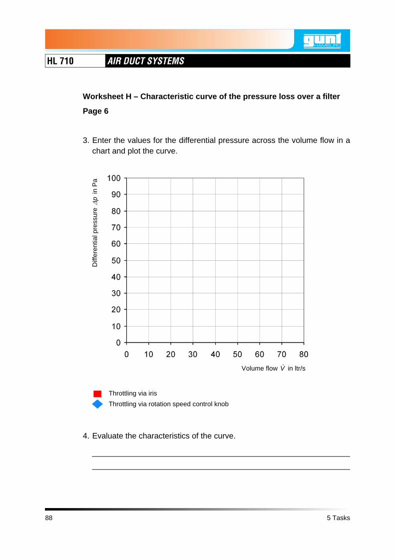
3. Enter the values for the differential pressure across the volume flow in achart and plot the curve.
4. Evaluate the characteristics of the curve.
Diff
eren
tial p
ress
ure
in P
aΔ
p
Volume flow in ltr/sV·
Throttling via iris
Throttling via rotation speed control knob
88 5 Tasks

HL 710 AIR DUCT SYSTEMS
All
right
s re
serv
ed, G
.U.N
.T. G
erät
ebau
, Bar
sbüt
tel,
Ger
man
y 01
/201
1
5.9 Worksheet I – Characteristic curve of the lower pipeline
Page 1
Objective
• To measure the static pressure relative to atmospheric pressure
• To measure the volume flow
• To present and evaluate a pipeline's characteristic curve
Measuring equipment
• Digital manometer
• Anemometer
Preparation for the experiment
1. Assemble the experiment setup according to Page 46 to Page 50.
CAUTIONSharp edges on the pipes.
Risk of hand injuries.
• Wear gloves.
2. Only the lower pipeline is considered. The middle and upper pipelines areshut off. To do this, proceed as follows:
– Set the throttle valves V7 and V9 to position 0 (closed).
– Set the irises V8 and V10 to position 1 (closed).
– Close the linear diffusers V3 and V4.
– Close the outlet valves V11, V12 and V13.
– Set the throttle valves V1 and V6 to position 9 (open).
– Set the irises V2 and V5 to position 6 (open).
5 Tasks 89

HL 710 AIR DUCT SYSTEMS
Worksheet I – Characteristic curve of the lower pipeline
Page 2
3. Observe the following safety precautions.
WARNINGNoise emission > 70dB(A).
Risk of hearing damage.
• Wear ear defenders.
WARNINGStrong blow out force at the fan outlet androtating parts in the fan outlet.
Risk of hand injuries.
• Do not reach into the fan outlet.
• Only operate the fan when a pipe is mountedon the fan outlet.
CAUTIONStrong suction force at the fan inlet.
Items and clothing may be drawn in.
• Do not stand near the fan inlet.
• Do not store loose items where they can bedrawn in by the fan.
90 5 Tasks

HL 710 AIR DUCT SYSTEMS
All
right
s re
serv
ed, G
.U.N
.T. G
erät
ebau
, Bar
sbüt
tel,
Ger
man
y 01
/201
1
Worksheet I – Characteristic curve of the lower pipeline
Page 3
NOTICEOverload of the electrics.
Risk of damage to the electrics.
• Ensure that the following currents are compliedwith during continuous load:120V: max 12,5A230V: max 6A
4. Turn the main switch on.
5. Turn the fan switch on.
5 Tasks 91

HL 710 AIR DUCT SYSTEMS
Worksheet I – Characteristic curve of the lower pipeline
Page 4
Exercise
1. Set the rotation speed control knob to 100% and take the following meas-urements:
• Use the digital manometer to measure the static pressure at measuringpoint P3 relative to the atmospheric pressure.
• Use the anemometer to measure the flow velocity at the outlet of thelower pipeline.
Gradually reduce the position of the rotation speed control knob andrepeat the measurements. Note down the results of your measurements inthe table.
2. Calculate the volume flow from the flow velocity and enter the results intothe table.
P3
Outlet of the lower pipeline
92 5 Tasks

HL 710 AIR DUCT SYSTEMS
All
right
s re
serv
ed, G
.U.N
.T. G
erät
ebau
, Bar
sbüt
tel,
Ger
man
y 01
/201
1
Worksheet I – Characteristic curve of the lower pipeline
Page 5
Rotation speed control knob
Measuring point P3
Outlet of the lower pipeline
in % Static pressure pP3
in Pa
Flow velocity measured
in m/s
Total volume flow
in ltr/s
vV·
5 Tasks 93

HL 710 AIR DUCT SYSTEMS
Worksheet I – Characteristic curve of the lower pipeline
Page 6
3. Enter the values for the pressure across the volume flow in a chart and plotthe curve.
4. Is it a system characteristic curve?
5. Evaluate the characteristics of the curve.
Pre
ssur
e p 3
in P
a
Volume flow in ltr/sV·
94 5 Tasks
HL 710 AIR DUCT SYSTEMS
All
right
s re
serv
ed, G
.U.N
.T. G
erät
ebau
, Bar
sbüt
tel,
Ger
man
y 01
/201
1
5.10 Worksheet J – Throttle characteristic curve of the lower pipeline
Page 1
Objective
• To measure the static pressure relative to atmospheric pressure
• To measure the volume flow
• To represent a throttle characteristic curve
Measuring equipment
• Digital manometer
• Anemometer
Preparation for the experiment
1. Assemble the experiment setup according to Page 46 to Page 50.
CAUTIONSharp edges on the pipes.
Risk of hand injuries.
• Wear gloves.
2. Only the lower pipeline is considered. The middle and upper pipelines areshut off. To do this, proceed as follows:
– Set the throttle valves V7 and V9 to position 0 (closed).
– Set the irises V8 and V10 to position 1 (closed).
– Close the linear diffusers V3 and V4.
– Close the outlet valves V11, V12 and V13.
– Set the throttle valves V1 and V6 to position 9 (open).
– Set the irises V2 and V5 to position 6 (open).
5 Tasks 95

HL 710 AIR DUCT SYSTEMS
Worksheet J – Throttle characteristic curve of the lower pipeline
Page 2
3. Observe the following safety precautions.
WARNINGNoise emission > 70dB(A).
Risk of hearing damage.
• Wear ear defenders.
WARNINGStrong blow out force at the fan outlet androtating parts in the fan outlet.
Risk of hand injuries.
• Do not reach into the fan outlet.
• Only operate the fan when a pipe is mountedon the fan outlet.
CAUTIONStrong suction force at the fan inlet.
Items and clothing may be drawn in.
• Do not stand near the fan inlet.
• Do not store loose items where they can bedrawn in by the fan.
96 5 Tasks

HL 710 AIR DUCT SYSTEMS
All
right
s re
serv
ed, G
.U.N
.T. G
erät
ebau
, Bar
sbüt
tel,
Ger
man
y 01
/201
1
Worksheet J – Throttle characteristic curve of the lower pipeline
Page 3
NOTICEOverload of the electrics.
Risk of damage to the electrics.
• Ensure that the following currents are compliedwith during continuous load:120V: max 12,5A230V: max 6A
4. Turn the main switch on.
5. Turn the fan switch on.
5 Tasks 97
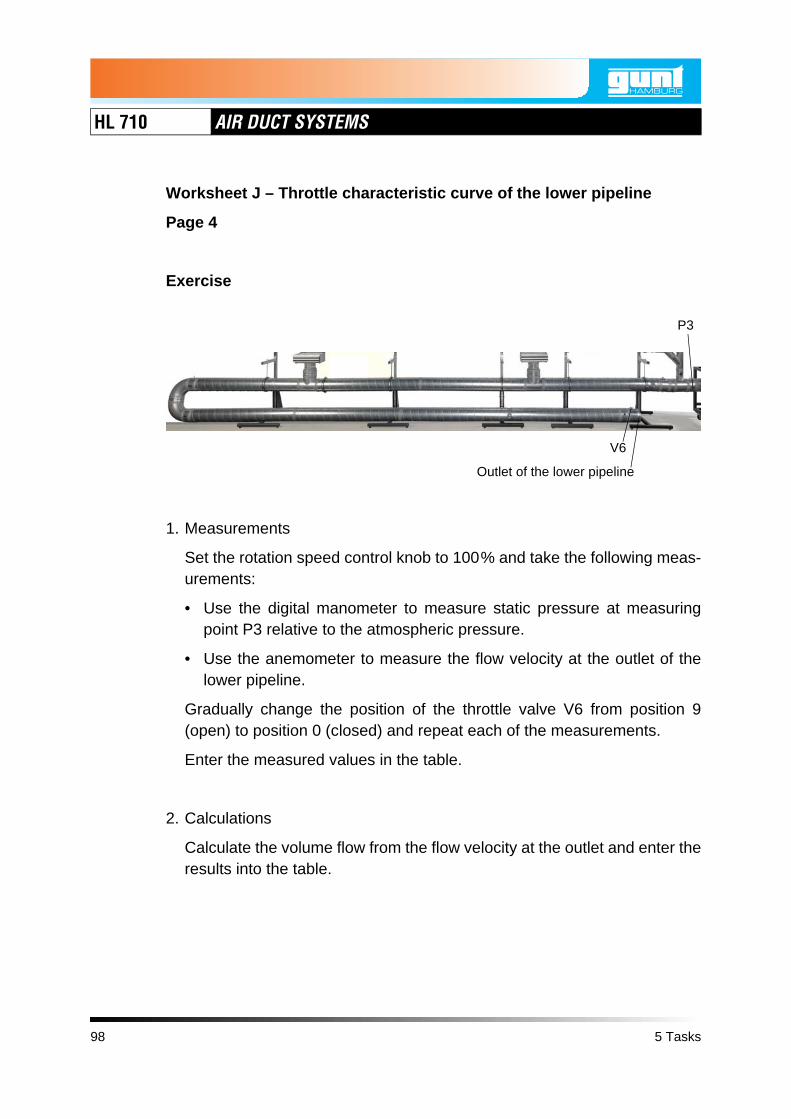
HL 710 AIR DUCT SYSTEMS
Worksheet J – Throttle characteristic curve of the lower pipeline
Page 4
Exercise
1. Measurements
Set the rotation speed control knob to 100% and take the following meas-urements:
• Use the digital manometer to measure static pressure at measuringpoint P3 relative to the atmospheric pressure.
• Use the anemometer to measure the flow velocity at the outlet of thelower pipeline.
Gradually change the position of the throttle valve V6 from position 9(open) to position 0 (closed) and repeat each of the measurements.
Enter the measured values in the table.
2. Calculations
Calculate the volume flow from the flow velocity at the outlet and enter theresults into the table.
P3
Outlet of the lower pipeline
V6
98 5 Tasks

HL 710 AIR DUCT SYSTEMS
All
right
s re
serv
ed, G
.U.N
.T. G
erät
ebau
, Bar
sbüt
tel,
Ger
man
y 01
/201
1
Worksheet J – Throttle characteristic curve of the lower pipeline
Page 5
Throttle valve Measuring point P3
Outlet of the lower pipeline
Position Static pressure pP3
in Pa
Flow velocity measured
in m/s
Total volume flow
in ltr/s
vV·
5 Tasks 99

HL 710 AIR DUCT SYSTEMS
Worksheet J – Throttle characteristic curve of the lower pipeline
Page 6
3. Characteristic curve
• Enter the values for the pressure across the volume flow in a chart andplot the curve.
4. Comparison
Compare the characteristic curve from Chapter 5.9, Page 89 (WorksheetI – Characteristic curve of the lower pipeline) with the characteristic curveon this page (Worksheet J – Throttle characteristic curve of the lower pipe-line).
What do the characteristic curves represent?
Pre
ssur
e p 3
in P
a
Volume flow in ltr/sV·
100 5 Tasks

HL 710 AIR DUCT SYSTEMS
All
right
s re
serv
ed, G
.U.N
.T. G
erät
ebau
, Bar
sbüt
tel,
Ger
man
y 01
/201
1
5.11 Worksheet K – Air distribution in the air duct system
Page 1
Objective
• To operate upper, middle and lower pipelines individually and in combina-tion with each other
• To measure the volume flows at outlet valves
• To evaluate the air distribution
Measuring equipment
• Anemometer
Preparation for the experiment
1. Assemble the experiment setup according to Page 46 to Page 50.
CAUTIONSharp edges on the pipes.
Risk of hand injuries.
• Wear gloves.
2. Create the starting state. To do this, proceed as follows:
– Set the throttle valve V6 to position 9 (open).
– Set the irises V2, V5, V8 and V10 to position 6 (open).
– Close the linear diffusers V3 and V4.
5 Tasks 101

HL 710 AIR DUCT SYSTEMS
Worksheet K – Air distribution in the air duct system
Page 2
3. Observe the following safety precautions.
WARNINGNoise emission > 70dB(A).
Risk of hearing damage.
• Wear ear defenders.
WARNINGStrong blow out force at the fan outlet androtating parts in the fan outlet.
Risk of hand injuries.
• Do not reach into the fan outlet.
• Only operate the fan when a pipe is mountedon the fan outlet.
CAUTIONStrong suction force at the fan inlet.
Items and clothing may be drawn in.
• Do not stand near the fan inlet.
• Do not store loose items where they can bedrawn in by the fan.
102 5 Tasks

HL 710 AIR DUCT SYSTEMS
All
right
s re
serv
ed, G
.U.N
.T. G
erät
ebau
, Bar
sbüt
tel,
Ger
man
y 01
/201
1
Worksheet K – Air distribution in the air duct system
Page 3
NOTICEOverload of the electrics.
Risk of damage to the electrics.
• Ensure that the following currents are compliedwith during continuous load:120V: max 12,5A230V: max 6A
4. Turn the main switch on.
5. Turn the fan switch on.
6. Turn the rotation speed control knob to 100%.
5 Tasks 103

HL 710 AIR DUCT SYSTEMS
Worksheet K – Air distribution in the air duct system
Page 4
Exercise
1. Opening or blocking individual pipelines
From the table on the next page, select the desired settings and open orblock the individual pipelines accordingly.
• To open the upper pipeline:Set the throttle valve V9 to position 9 (open).
• To block the upper pipeline: Set the throttle valve V9 to position 0 (closed).
• To open the middle pipeline:Set the throttle valve V7 to position 9 (open).
• To block the middle pipeline:Set the throttle valve V7 to position 0 (closed).
• To open the lower pipeline:Set the throttle valve V1 to position 9 (open).
• To block the lower pipeline:Set the throttle valve V1 to position 0 (closed).
V9
Outlet of the lower pipeline
V7V13Outlet of the middle pipeline
V1
V12 V11
104 5 Tasks

HL 710 AIR DUCT SYSTEMS
All
right
s re
serv
ed, G
.U.N
.T. G
erät
ebau
, Bar
sbüt
tel,
Ger
man
y 01
/201
1
Worksheet K – Air distribution in the air duct system
Page 5
2. Measurements
Use the anemometer and the volume flow hood to measure the volumeflows at
– the outlet valves V11, V12 and V13
– the outlet of the middle pipeline
– the outlet of the lower pipeline
As the throttle valves do not fully seal the flow cross-section, the meas-urements must always be taken at all outlet valves and pipe outlets.
Note down the results of your measurements in the table.
white: closedyellow: open
Upper pipeline
Middle pipeline
Lower pipeline
Upper pipeline Middle pipeline
Lower pipeline
Sum of all pipe-
linesV11 V12 V13 Sum
V11, V12 and V13
Outlet Outlet
Volume flow in ltr/s
open open open
open open closed
open closed open
open closed closed
closed open open
closed open closed
closed closed open
closed closed closed
V·
5 Tasks 105

HL 710 AIR DUCT SYSTEMS
Worksheet K – Air distribution in the air duct system
Page 6
3. Evaluate the measurement results.
106 5 Tasks

HL 710 AIR DUCT SYSTEMS
All
right
s re
serv
ed, G
.U.N
.T. G
erät
ebau
, Bar
sbüt
tel,
Ger
man
y 01
/201
1
6 Solutions
Solutions
Worksheet A – Components of the air duct system Page 108
Worksheet B – Assembling a complex air duct system Page 111
Worksheet C – Two methods for determining the dynamic pressure Page 118
Worksheet D – Two methods for determining the flow velocity Page 123
Worksheet E – Two methods for determining the volume flow Page 130
Worksheet F – Pressure loss and resistance coefficient of a composite 180° bend
Page 138
Worksheet G – Characteristic curve of the pressure loss over a 90° bend Page 143
Worksheet H – Characteristic curve of the pressure loss over a filter Page 149
Worksheet I – Characteristic curve of the lower pipeline Page 155
Worksheet J – Throttle characteristic curve of the lower pipeline Page 161
Worksheet K – Air distribution in the air duct system Page 167
6 Solutions 107

HL 710 AIR DUCT SYSTEMS
6.1 Worksheet A – Components of the air duct system
Page 1
Objective
To recognise and name the components of an air duct system
Exercise
1. On the following page you will see a section of an air duct system.
Enter the item numbers of the components from the table in the image.
108 6 Solutions

HL 710 AIR DUCT SYSTEMS
All
right
s re
serv
ed, G
.U.N
.T. G
erät
ebau
, Bar
sbüt
tel,
Ger
man
y 01
/201
1
Worksheet A – Components of the air duct system
Page 2
Item number Component
1 Fan
2 Control cabinet
3 Assembly stand
4 Pipe clamp
5 Pipe
6 Bends and branches
7 Pressure measuring points
8 Iris
26
3
4
1
6
6
58
77 8
6 Solutions 109

HL 710 AIR DUCT SYSTEMS
Worksheet A – Components of the air duct system
Page 3
2. Here you can see some components that can be fitted to the air duct.
Enter the names of the components in table.
Item 1 Item 2 Item 3
Item 8Item 5 Item 6 Item 7
Item 4
Item number Component
1 Outlet valve
2 90° branch
3 Reducer
4 Filter cartridge for filter matting and pocket filter
5 90° bend and 45° bend
6 45° branch
7 Linear diffuser
8 90° branch with reducer
110 6 Solutions

HL 710 AIR DUCT SYSTEMS
All
right
s re
serv
ed, G
.U.N
.T. G
erät
ebau
, Bar
sbüt
tel,
Ger
man
y 01
/201
1
6.2 Worksheet B – Assembling a complex air duct system
Page 1
Objective
• To assemble an air duct system
• To recognise possible pressure measurements
Exercise
On the following pages you will see a complex air duct system, representedas
• Illustration
• Piping diagram
• Parts list
• List of measuring points.
6 Solutions 111

HL 710 AIR DUCT SYSTEMS
Illus
trat
ion
Worksheet B – Assembling a complex air duct system
Page 2
112 6 Solutions

HL 710 AIR DUCT SYSTEMS
All
right
s re
serv
ed, G
.U.N
.T. G
erät
ebau
, Bar
sbüt
tel,
Ger
man
y 01
/201
1
Pip
ing
diag
ram
Worksheet B – Assembling a complex air duct system
Page 3
6 Solutions 113

HL 710 AIR DUCT SYSTEMS
Worksheet B – Assembling a complex air duct system
Page 4
Parts list, part 1
Symbol Name Nominal diameter
Quan-tity
Identifi-cation letter
Fan 1
Assembly stand 5
Pipe, length 1600mmDN 100 8
DN 200 8
Sleeve
DN 100 5
DN 160 2
DN 200 5
Plug connectorDN 100 4
DN 200 7
45° bend DN 100 1
90° bendDN 100 3
DN 200 2
45° branch DN 100 1
90° branchDN 100 2
DN 200 2
90° branch with reducerDN 200 - DN 100
1
114 6 Solutions

HL 710 AIR DUCT SYSTEMS
All
right
s re
serv
ed, G
.U.N
.T. G
erät
ebau
, Bar
sbüt
tel,
Ger
man
y 01
/201
1
Worksheet B – Assembling a complex air duct system
Page 5
Parts list, part 2
Symbol Name Nominal diameter
Quan-tity
Identifi-cation letter
Reducer
DN 200 - DN 160
2
DN 160 - DN 100
1
Throttle valveDN 100 2 V7, V9
DN 200 2 V1, V6
IrisDN 100 2 V8, V10
DN 200 2 V2, V5
Pipe with measuring point for static pressure
DN 100 6
DN 200 2
Pipe with measuring point for static pressure and measuring point for total pressure
DN 100 2
DN 180 1
DN 200 2
Pocket filter DN 100 1 F1
Filter (filter matting) DN 100 1 F2
Linear diffuser DN 160 2 V3, V4
Outlet valve DN 100 3V11, V12, V13
Adhesive tape
6 Solutions 115

HL 710 AIR DUCT SYSTEMS
Worksheet B – Assembling a complex air duct system
Page 6
List of measuring points
Type of measuring point
Measuring point identification letter
Nominal diameter of
the pipe
Cross-section area of the pipe
Measuring point for static pressure
P13, P14, P16, P17, P18, P19, P20, P21, P22, P24, P25, P26, P27, P28
DN 100 7.854mm2
P1 DN 180 25.447mm2
P3, P5, P6, P7, P9, P10, P11, P12
DN 200 31.416mm2
Measuring point for total pressure
P15, P23 DN 100 7.854mm2
P2 DN 180 25.447mm2
P4, P8 DN 200 31.416mm2
116 6 Solutions

HL 710 AIR DUCT SYSTEMS
All
right
s re
serv
ed, G
.U.N
.T. G
erät
ebau
, Bar
sbüt
tel,
Ger
man
y 01
/201
1
Worksheet B – Assembling a complex air duct system
Page 7
1. Assemble the system shown from the components of the HL 710 air ductsystem and tightly seal the joints with tape.
CAUTIONSharp edges on the pipes.
Risk of hand injuries.
• Wear gloves.
This experiment layout is the basis for the worksheets in Chapter 6.3,Page 118, to Chapter 6.11, Page 167.
2. Pressure measurement points are shown in the piping diagram onPage 113.
Which pressure measurements could you perform on this system? Namethe measuring points and the purpose of each measurement.
Pressure measuring points
Purpose of the measurement
Example: P3 and P12 Pressure drop across the lower pipeline at different volume flows.
P20 and P21 Differential pressure across composite 180° bend at differ-ent volume flows.
P10 and P11 Differential pressure across the iris at constant volume flow and different positions of the iris to determine the flow veloc-ity.
P13, P14 and P22 Comparison of pressure drops in different flow directions of a branch at different volume flows.
P7 and P8 Measurement of the total pressure and static pressure, and calculation of the dynamic pressure and the flow velocity.
P14 and P16 Pressure loss through the throttle valve at different positions of the throttle valve.
6 Solutions 117

HL 710 AIR DUCT SYSTEMS
6.3 Worksheet C – Two methods for determining the dynamic pressure
Page 1
Objective
• To measure dynamic pressure as differential pressure
• To measure total pressure and static pressure and to calculate thedynamic pressure
• To compare results of both methods
• Familiarisation with the digital manometer
Measuring equipment
• Digital manometer
118 6 Solutions

HL 710 AIR DUCT SYSTEMS
All
right
s re
serv
ed, G
.U.N
.T. G
erät
ebau
, Bar
sbüt
tel,
Ger
man
y 01
/201
1
Worksheet C – Two methods for determining the dynamic pressure
Page 2
Preparation for the experiment
1. Assemble the experiment setup according to Page 112 to Page 116.
CAUTIONSharp edges on the pipes.
Risk of hand injuries.
• Wear gloves.
2. Only the upper pipeline is considered. The lower and middle pipelines areshut off. Proceed as follows:
– Set the throttle valves V1, V6 and V7 to position 0 (closed).
– Set the irises V2, V5 and V8 to position 1 (closed).
– Close the linear diffusers V3 and V4.
– Set the throttle valve V9 to position 9 (open).
– Set the iris V10 to position 6 (open).
– Screw out the plates of the outlet valves V11, V12 and V13 a bit.
3. Observe the following safety precautions.
WARNINGNoise emission > 70dB(A).
Risk of hearing damage.
• Wear ear defenders.
6 Solutions 119
HL 710 AIR DUCT SYSTEMS
Worksheet C – Two methods for determining the dynamic pressure
Page 3
WARNINGStrong blow out force at the fan outlet androtating parts in the fan outlet.
Risk of hand injuries.
• Do not reach into the fan outlet.
• Only operate the fan when a pipe is mountedon the fan outlet.
CAUTIONStrong suction force at the fan inlet.
Items and clothing may be drawn in.
• Do not stand near the fan inlet.
• Do not store loose items where they can bedrawn in by the fan.
NOTICEOverload of the electrics.
Risk of damage to the electrics.
• Ensure that the following currents are compliedwith during continuous load:120V: max 12,5A230V: max 6A
4. Turn the main switch on.
5. Turn the fan switch on.
6. Turn the rotation speed control knob to 100%.
120 6 Solutions

HL 710 AIR DUCT SYSTEMS
All
right
s re
serv
ed, G
.U.N
.T. G
erät
ebau
, Bar
sbüt
tel,
Ger
man
y 01
/201
1
Worksheet C – Two methods for determining the dynamic pressure
Page 4
Exercise
1. Measuring dynamic pressure as differential pressure
• Use the digital manometer to measure the differential pressure betweenmeasuring point P22 and measuring point P23.
This differential pressure corresponds to the dynamic pressure pdyn1.
• Note down the measurement result:
Measuring points 22 and 23
Dynamic pressure pdyn1in Pa
65
P22
P23
6 Solutions 121

HL 710 AIR DUCT SYSTEMS
Worksheet C – Two methods for determining the dynamic pressure
Page 5
2. Measuring total pressure and static pressure and from this calculating thedynamic pressure
• Use the digital manometer to measure the total pressure at measuringpoint P23 and note down the measured value in the table below.
• Use the digital manometer to measure the static pressure at measuringpoint P22 and note down the measured value.
• Calculate the difference between total pressure and static pressure.This is the dynamic pressure pdyn2.
Measurements:
3. Comparing both dynamic pressures
Compare the dynamic pressure pdyn1 from task 1 with the dynamic pres-sure pdyn2 from task 2.
pdyn1 is 65Pa, pdyn2 is 62Pa.
The difference between the two values is 5%, thus it is small.
Measuring point 23 Measuring point 22 Measuring points 22 and 23
Total pressure ptotal in Pa
Static pressure pstat in Pa
Dynamic pressure pdyn2 in Pa
800 738 62
122 6 Solutions
HL 710 AIR DUCT SYSTEMS
All
right
s re
serv
ed, G
.U.N
.T. G
erät
ebau
, Bar
sbüt
tel,
Ger
man
y 01
/201
1
6.4 Worksheet D – Two methods for determining the flow velocity
Page 1
Objective
• Familiarisation with measuring the flow velocity
• Familiarisation with measuring dynamic pressure as differential pressure
• To calculate the flow velocity from the dynamic pressure
• To compare measured and calculated flow velocities
• Familiarisation with the anemometer
Measuring equipment
• Digital manometer
• Anemometer
6 Solutions 123

HL 710 AIR DUCT SYSTEMS
Worksheet D – Two methods for determining the flow velocity
Page 2
Preparation for the experiment
1. Assemble the experiment setup according to Page 112 to Page 116.
CAUTIONSharp edges on the pipes.
Risk of hand injuries.
• Wear gloves.
2. Only the lower pipeline is considered. The middle and upper pipelines areshut off. To do this, proceed as follows:
– Set the throttle valves V7 and V9 to position 0 (closed).
– Set the irises V8 and V10 to position 1 (closed).
– Close the linear diffusers V3 and V4.
– Close the outlet valves V11, V12 and V13.
– Set the throttle valves V1 and V6 to position 9 (open).
– Set the irises V2 and V5 to position 6 (open).
3. Observe the following safety precautions.
WARNINGNoise emission > 70dB(A).
Risk of hearing damage.
• Wear ear defenders.
124 6 Solutions

HL 710 AIR DUCT SYSTEMS
All
right
s re
serv
ed, G
.U.N
.T. G
erät
ebau
, Bar
sbüt
tel,
Ger
man
y 01
/201
1
Worksheet D – Two methods for determining the flow velocity
Page 3
WARNINGStrong blow out force at the fan outlet androtating parts in the fan outlet.
Risk of hand injuries.
• Do not reach into the fan outlet.
• Only operate the fan when a pipe is mountedon the fan outlet.
CAUTIONStrong suction force at the fan inlet.
Items and clothing may be drawn in.
• Do not stand near the fan inlet.
• Do not store loose items where they can bedrawn in by the fan.
NOTICEOverload of the electrics.
Risk of damage to the electrics.
• Ensure that the following currents are compliedwith during continuous load:120V: max 12,5A230V: max 6A
4. Turn the main switch on.
5. Turn the fan switch on.
6 Solutions 125

HL 710 AIR DUCT SYSTEMS
Worksheet D – Two methods for determining the flow velocity
Page 4
Exercise
1. Taking measurements
Set the rotation speed control knob to 100% and take the following meas-urements:
• Use the digital manometer to measure the differential pressure betweenmeasuring points P7 and P8. This is the dynamic pressure at measuringpoint P8. Note down the value in the table on the next page.
• Use the anemometer to measure the flow velocity at the outlet of thelower pipeline. Note down the value in the table.
Gradually reduce the position of the rotation speed control knob andrepeat the measurements. Note down your measurement results in thetable on the following page.
P8 P7
Outlet of the lower pipeline
126 6 Solutions

HL 710 AIR DUCT SYSTEMS
All
right
s re
serv
ed, G
.U.N
.T. G
erät
ebau
, Bar
sbüt
tel,
Ger
man
y 01
/201
1
Worksheet D – Two methods for determining the flow velocity
Page 5
2. Calculation
Calculate the flow velocities from the dynamic pressures at measuringpoint P8 and enter the results in the table.
Calculation method:
v Flow velocitypdyn Dynamic pressure
Density of the flow mediumAir: 1,225kg/m3 at 15°C
Rotation speed control knob
Measuring point P8 Outlet of the lower pipeline
in % Dynamic pressure pP8
in Pa
Flow velocity calculated
in m/s
Flow velocity measured
in m/s
100 77 11,2 16,5
80 72 10,8 16,0
60 55 9,5 14,0
50 22 6,0 8,9
40 10 4,0 5,8
35 5 2,9 4,2
v v
v2 pdyn⋅
ρ-------------------=
ρ
6 Solutions 127

HL 710 AIR DUCT SYSTEMS
Worksheet D – Two methods for determining the flow velocity
Page 6
3. Comparison
Compare the measured and calculated flow velocities and evaluate the dif-ferences.
The flow velocities measured at the outlet of the lower pipeline are higher
than the flow velocities calculated for measuring point P8.
Reason: In an open jet like at the outlet of the lower pipeline the flow
velocity is highest at the middle of the open jet. With increasing horizontal
and vertical distance from the centre, the flow velocity in the open jet
decreases, see following example illustration.
Fig. 6.1 Example velocity profile in the open jet of a pipe with 130mm diameter
Flow velocity v in m/s
Dis
tanc
e z
from
the
cent
re in
mm
100
80
60
40
20
0
20
40
60
80
1000 5 10 15 20 25
x=200mx=300m
x=100m
x=150m
x=250m
x = horizontal distance from the pipe outlet
128 6 Solutions
HL 710 AIR DUCT SYSTEMS
All
right
s re
serv
ed, G
.U.N
.T. G
erät
ebau
, Bar
sbüt
tel,
Ger
man
y 01
/201
1
Worksheet D – Two methods for determining the flow velocity
Page 7
4. Improving the measurements
With which measurements at the measuring points P8 and at the outlet ofthe lower pipeline could you achieve better results?
• Option 1: Measure the flow velocity at different positions of the
open jet and take the mean value from this.
• Option 2: Measure the volume flow at the outlet of the lower
pipeline with the anemometer and the volume flow hood.
6 Solutions 129

HL 710 AIR DUCT SYSTEMS
6.5 Worksheet E – Two methods for determining the volume flow
Page 1
Objective
• Familiarisation with the volume flow at outlet valves
• Familiarisation with measuring dynamic pressure as differential pressure
• To calculate the volume flow from the dynamic pressure
• To compare measured and calculated volume flows
Measuring equipment
• Digital manometer
• Anemometer
Preparation for the experiment
1. Assemble the experiment setup according to Page 112 to Page 116.
CAUTIONSharp edges on the pipes.
Risk of hand injuries.
• Wear gloves.
2. Only the upper pipeline is considered. The lower and middle pipelines areshut off. Proceed as follows:
– Set the throttle valves V1, V6 and V7 to position 0 (closed).
– Set the irises V2, V5 and V8 to position 1 (closed).
– Close the linear diffusers V3 and V4.
– Set the throttle valve V9 to position 9 (open).
– Set the iris V10 to position 6 (open).
130 6 Solutions

HL 710 AIR DUCT SYSTEMS
All
right
s re
serv
ed, G
.U.N
.T. G
erät
ebau
, Bar
sbüt
tel,
Ger
man
y 01
/201
1
Worksheet E – Two methods for determining the volume flow
Page 2
3. Observe the following safety precautions.
WARNINGNoise emission > 70dB(A).
Risk of hearing damage.
• Wear ear defenders.
WARNINGStrong blow out force at the fan outlet androtating parts in the fan outlet.
Risk of hand injuries.
• Do not reach into the fan outlet.
• Only operate the fan when a pipe is mountedon the fan outlet.
CAUTIONStrong suction force at the fan inlet.
Items and clothing may be drawn in.
• Do not stand near the fan inlet.
• Do not store loose items where they can bedrawn in by the fan.
6 Solutions 131

HL 710 AIR DUCT SYSTEMS
Worksheet E – Two methods for determining the volume flow
Page 3
NOTICEOverload of the electrics.
Risk of damage to the electrics.
• Ensure that the following currents are compliedwith during continuous load:120V: max 12,5A230V: max 6A
4. Turn the main switch on.
5. Turn the fan switch on.
6. Set the rotation speed control knob to 100%.
132 6 Solutions

HL 710 AIR DUCT SYSTEMS
All
right
s re
serv
ed, G
.U.N
.T. G
erät
ebau
, Bar
sbüt
tel,
Ger
man
y 01
/201
1
Worksheet E – Two methods for determining the volume flow
Page 4
Exercise
1. Measuring flow rates at outlet valves
• Screw out the plates of the outlet valves V11, V12 and V13 all the way,so that all three outlet valves are open simultaneously.
• Use the anemometer and the volume flow hood to measure the volumeflow at the outlet valves V11, V12 and V13.
Note down the measurement results in the following table:
Outlet valve V11 Outlet valve V12 Outlet valve V13
Volume flow in ltr/s
Volume flow in ltr/s
Volume flow in ltr/s
85 41 31
V13 V12 V11
V· V11 V· V12 V· V13
6 Solutions 133

HL 710 AIR DUCT SYSTEMS
Worksheet E – Two methods for determining the volume flow
Page 5
• Screw the plates back into the outlet valves V11, V12 and V13.
• Turn the plates in or out until you are measuring the same volume flowat all three outlet valves.
Note down the measurement results as an aid:
Outlet valve V11 Outlet valve V12 Outlet valve V13
Volume flow in ltr/s
Volume flow in ltr/s
Volume flow in ltr/s
Adjusted, same volume flow at the exhaust valves V11, V12 and V13
45
Sum of the volume flow at the outlet valves V11, V12 and V13
135
V· V11 V· V12 V· V13
V· sum
134 6 Solutions

HL 710 AIR DUCT SYSTEMS
All
right
s re
serv
ed, G
.U.N
.T. G
erät
ebau
, Bar
sbüt
tel,
Ger
man
y 01
/201
1
Worksheet E – Two methods for determining the volume flow
Page 6
2. Measuring dynamic pressure
• Use the digital manometer to measure the differential pressure betweenmeasuring point P22 and measuring point P23.
This differential pressure corresponds to the dynamic pressure.
• Note down the measurement result in the table.
Measuring point 23
Dynamic pressure pdyn in Pa
65
P22
P23
6 Solutions 135

HL 710 AIR DUCT SYSTEMS
Worksheet E – Two methods for determining the volume flow
Page 7
3. Calculating volume flow
Calculate the volume flow from the dynamic pressure at the measuringpoint P23.
Your calculation result:
= 81ltr/s
Calculation method:
Volume flowAD Cross-section area of the pipe
here: 0,00785m2
pdyn Dynamic pressurehere: 65PaDensity of the flow mediumAir: 1,225kg/m3 at 15°C
V· calc
V· AD2 pdyn⋅
ρ-------------------⋅=
V·
ρ
136 6 Solutions

HL 710 AIR DUCT SYSTEMS
All
right
s re
serv
ed, G
.U.N
.T. G
erät
ebau
, Bar
sbüt
tel,
Ger
man
y 01
/201
1
Worksheet E – Two methods for determining the volume flow
Page 8
4. Comparing measured and calculated volume flow
The volume flow you calculated in task 1 is:
135ltr/s
The volume flow you measured in task 2 is:
81ltr/s
Compare the two volume flows. Explain the different values.
The measuring points P22 and P23 for the calculation of the volume flow
are located just behind a branch. Here, the air flow exhibits
turbulence, measurement conditions are not favourable.
At the measurement points V11, V12 and V13 the position of the
measuring points is not significant. At these measuring points volume flow
is measured, which is not affected by turbulence.
How could you improve the measurement of the dynamic pressure to getbetter results for the calculated volume flow ?
The dynamic pressure should be measured at a measuring point,
which is preceded by an approximately 1m long calmed section. In the
upper pipeline, there is no such measuring point available.
V· sum
V· calc
V· calc
V· sum
V· calc
6 Solutions 137
HL 710 AIR DUCT SYSTEMS
6.6 Worksheet F – Pressure loss and resistance coefficient of a composite 180° bend
Page 1
Objective
• To measure the pressure loss of a composite 180° bend
• To calculate the resistance coefficient of the bend
• Familiarisation with an inclined tube manometer
Measuring equipment
• Inclined tube manometer
• Anemometer
Preparation for the experiment
1. Assemble the experiment setup according to Page 112 to Page 116.
CAUTIONSharp edges on the pipes.
Risk of hand injuries.
• Wear gloves.
2. Only the lower pipeline is considered. The middle and upper pipelines areshut off. To do this, proceed as follows:
– Set the throttle valves V7 and V9 to position 0 (closed).
– Set the irises V8 and V10 to position 1 (closed).
– Close the linear diffusers V3 and V4.
– Close the outlet valves V11, V12 and V13.
– Set the throttle valves V1 and V6 to position 9 (open).
– Set the irises V2 and V5 to position 6 (open).
138 6 Solutions

HL 710 AIR DUCT SYSTEMS
All
right
s re
serv
ed, G
.U.N
.T. G
erät
ebau
, Bar
sbüt
tel,
Ger
man
y 01
/201
1
Worksheet F – Pressure loss and resistance coefficient of a composite 180° bend
Page 2
3. Observe the following safety precautions.
WARNINGNoise emission > 70dB(A).
Risk of hearing damage.
• Wear ear defenders.
WARNINGStrong blow out force at the fan outlet androtating parts in the fan outlet.
Risk of hand injuries.
• Do not reach into the fan outlet.
• Only operate the fan when a pipe is mountedon the fan outlet.
CAUTIONStrong suction force at the fan inlet.
Items and clothing may be drawn in.
• Do not stand near the fan inlet.
• Do not store loose items where they can bedrawn in by the fan.
6 Solutions 139

HL 710 AIR DUCT SYSTEMS
Worksheet F – Pressure loss and resistance coefficient of a composite 180° bend
Page 3
NOTICEOverload of the electrics.
Risk of damage to the electrics.
• Ensure that the following currents are compliedwith during continuous load:120V: max 12,5A230V: max 6A
4. Turn the main switch on.
5. Turn the fan switch on.
140 6 Solutions

HL 710 AIR DUCT SYSTEMS
All
right
s re
serv
ed, G
.U.N
.T. G
erät
ebau
, Bar
sbüt
tel,
Ger
man
y 01
/201
1
Worksheet F – Pressure loss and resistance coefficient of a composite 180° bend
Page 4
Exercise
1. Measuring
Set the rotation speed control knob to 100%.
Take the following measurements:
• Use the inclined tube manometer to measure the differential pressurebetween measuring points P7 and P9. This is the differential pressureacross the composite 180° bend.
• Use the anemometer to measure the flow velocity at the outlet of thelower pipeline.
Gradually reduce the position of the rotation speed control knob andrepeat the measurements.
Note down your measurement results in the table on the following page.
P9
P7
Outlet of the lower pipeline
6 Solutions 141

HL 710 AIR DUCT SYSTEMS
Worksheet F – Pressure loss and resistance coefficient of a composite 180° bend
Page 5
2. Calculating
From the differential pressure and the flow velocity at the outlet,calculate the resistance coefficient of the composite 180° bend and enterthe results into the table.
What is the relationship between flow velocity and resistance coefficient?
Calculation method:
Resistance coefficientDifferential pressureDensity of the flow mediumAir: 1,225kg/m3 at 15°C
v Flow velocity
The resistance coefficient is independent of the flow velocity.
Rotation speed control knob
Measuring point P7 - measuring point P9
Outlet of the lower pipeline
Composite 180°-bend
in % Differential pressure
in Pa
Flow velocity in m/s
measured
Resistance coefficient
100 77 16,5 0,461
80 72 16,0 0,459
60 55 14,0 0,458
50 22 8,9 0,453
40 10 5,8 0,485
35 5 4,2 0,463
ΔpP7-P9
ΔpP7-P9
vζ
ζ 2 Δ⋅ p
ρ v 2⋅---------------=
ζΔpρ
ζ
142 6 Solutions

HL 710 AIR DUCT SYSTEMS
All
right
s re
serv
ed, G
.U.N
.T. G
erät
ebau
, Bar
sbüt
tel,
Ger
man
y 01
/201
1
6.7 Worksheet G – Characteristic curve of the pressure loss over a 90° bend
Page 1
Objective
• To measure the pressure loss over a 90° bend
• To measure the volume flow
• To draw and evaluate the characteristic curve of the pressure loss over thevolume flow
Measuring equipment
• Digital manometer
• Anemometer
Preparation for the experiment
1. Assemble the experiment setup according to Page 112 to Page 116.
CAUTIONSharp edges on the pipes.
Risk of hand injuries.
• Wear gloves.
2. Only the upper pipeline is considered. The lower and middle pipelines areshut off. To do this, proceed as follows:
– Set the throttle valves V1, V6 and V7 to position 0 (closed).
– Set the irises V2, V5 and V8 to position 1 (closed).
– Close the linear diffusers V3 and V4.
– Set the throttle valve V9 to position 9 (open).
– Screw out the plates of the outlet valves V11, V12 and V13 a bit.
6 Solutions 143

HL 710 AIR DUCT SYSTEMS
Worksheet G – Characteristic curve of the pressure loss over a 90° bend
Page 2
3. Observe the following safety precautions.
WARNINGNoise emission > 70dB(A).
Risk of hearing damage.
• Wear ear defenders.
WARNINGStrong blow out force at the fan outlet androtating parts in the fan outlet.
Risk of hand injuries.
• Do not reach into the fan outlet.
• Only operate the fan when a pipe is mountedon the fan outlet.
CAUTIONStrong suction force at the fan inlet.
Items and clothing may be drawn in.
• Do not stand near the fan inlet.
• Do not store loose items where they can bedrawn in by the fan.
144 6 Solutions

HL 710 AIR DUCT SYSTEMS
All
right
s re
serv
ed, G
.U.N
.T. G
erät
ebau
, Bar
sbüt
tel,
Ger
man
y 01
/201
1
Worksheet G – Characteristic curve of the pressure loss over a 90° bend
Page 3
NOTICEOverload of the electrics.
Risk of damage to the electrics.
• Ensure that the following currents are compliedwith during continuous load:120V: max 12,5A230V: max 6A
4. Turn the main switch on.
5. Turn the fan switch on.
6. Turn the rotation speed control knob to 100%.
6 Solutions 145

HL 710 AIR DUCT SYSTEMS
Worksheet G – Characteristic curve of the pressure loss over a 90° bend
Page 4
Exercise
1. Taking measurements
• Set the iris V10 to position 1 (closed).
• Take the following measurements:
– Use the digital manometer to measure the differential pressurebetween measuring points P24 and P25. This is the differential pres-sure across the 90° bend.
– Use the anemometer and the volume flow hood to measure the vol-ume flow at the outlet valves V11, V12 and V13. Generate the sumof the three volume flows.
Gradually change the position of the iris V10 from position 1 (closed) toposition 6 (open) and repeat each of the measurements.
V13 V12 V11 P24P25V10
146 6 Solutions

HL 710 AIR DUCT SYSTEMS
All
right
s re
serv
ed, G
.U.N
.T. G
erät
ebau
, Bar
sbüt
tel,
Ger
man
y 01
/201
1
Worksheet G – Characteristic curve of the pressure loss over a 90° bend
Page 5
Iris Measuring point P24 - measuring point P25
Outlet valve V11
Outlet valve V12
Outlet valve V13
Sum V11, V12 and
V13
Position Differen-tial pres-
sure
in Pa
Volume flow
in ltr/s
Volume flow
in ltr/s
Volume flow
in ltr/s
Total vol-ume flow
in ltr/s
1 (closed) 29 49 24 19 92
2 37 57 28 21 106
3 55 66 32 25 123
4 70 76 36 28 140
5 89 84 40 31 155
6 (open) 113 90 44 34 168
ΔpP24-P25
V· V11 V· V12 V· V13
V· sum
6 Solutions 147

HL 710 AIR DUCT SYSTEMS
Worksheet G – Characteristic curve of the pressure loss over a 90° bend
Page 6
2. Enter the values for the differential pressure across the total volume flowin a chart and plot the curve.
3. Evaluate the characteristics of the curve.
The differential pressure of the 90° bend increases in proportion to the
square of the volume flow.
Diff
eren
tial p
ress
ure
in P
aΔ
p
Volume flow in ltr/sV· sum
148 6 Solutions

HL 710 AIR DUCT SYSTEMS
All
right
s re
serv
ed, G
.U.N
.T. G
erät
ebau
, Bar
sbüt
tel,
Ger
man
y 01
/201
1
6.8 Worksheet H – Characteristic curve of the pressure loss over a filter
Page 1
Objective
• Familiarisation with throttling via iris and via rotation speed control knob
• To determine the pressure loss over a filter
Measuring equipment
• Digital manometer
• Anemometer
Preparation for the experiment
1. Assemble the experiment setup according to Page 112 to Page 116.
CAUTIONSharp edges on the pipes.
Risk of hand injuries.
• Wear gloves.
2. Only the middle pipeline is considered. The lower and upper pipelines areshut off. To do this, proceed as follows:
– Set the throttle valves V1, V6 and V9 to position 0 (closed).
– Set the irises V2, V5 and V10 to position 1 (closed).
– Close the disc valves V11, V12 and V13.
– Close the linear diffusers V3 and V4.
– Install the filter element in the pocket filter F1.
– Set the throttle valve V7 to position 9 (open).
– Set the iris V8 to position 6 (open).
6 Solutions 149

HL 710 AIR DUCT SYSTEMS
Worksheet H – Characteristic curve of the pressure loss over a filter
Page 2
3. Observe the following safety precautions.
WARNINGNoise emission > 70dB(A).
Risk of hearing damage.
• Wear ear defenders.
WARNINGStrong blow out force at the fan outlet androtating parts in the fan outlet.
Risk of hand injuries.
• Do not reach into the fan outlet.
• Only operate the fan when a pipe is mountedon the fan outlet.
CAUTIONStrong suction force at the fan inlet.
Items and clothing may be drawn in.
• Do not stand near the fan inlet.
• Do not store loose items where they can bedrawn in by the fan.
150 6 Solutions

HL 710 AIR DUCT SYSTEMS
All
right
s re
serv
ed, G
.U.N
.T. G
erät
ebau
, Bar
sbüt
tel,
Ger
man
y 01
/201
1
Worksheet H – Characteristic curve of the pressure loss over a filter
Page 3
NOTICEOverload of the electrics.
Risk of damage to the electrics.
• Ensure that the following currents are compliedwith during continuous load:120V: max 12,5A230V: max 6A
4. Turn the main switch on.
5. Turn the fan switch on.
6. Turn the rotation speed control knob to 100%.
6 Solutions 151

HL 710 AIR DUCT SYSTEMS
Worksheet H – Characteristic curve of the pressure loss over a filter
Page 4
Exercise
1. Measurements with throttling via the iris
• Use the digital manometer to measure the differential pressure betweenmeasuring points P19 and P18. This is the pressure loss across the fil-ter F1.
• Use the anemometer and the volume flow hood to measure the volumeflow at the outlet of the middle pipeline.
Gradually change the position of the iris V8 from position 6 (open) to posi-tion 1 (closed) and repeat each of the measurements.
Iris Measuring point P19 - measuring point P18
Outlet of the middle pipeline
Position Differential pressure
in Pa
Volume flow in ltr/s
1 (open) 96 71
2 93 69
3 86 65
4 79 61
5 69 54
6 (closed) 64 51
Outlet of the middle pipeline V8P19 P18
Δpp19-p18
V·
152 6 Solutions

HL 710 AIR DUCT SYSTEMS
All
right
s re
serv
ed, G
.U.N
.T. G
erät
ebau
, Bar
sbüt
tel,
Ger
man
y 01
/201
1
Worksheet H – Characteristic curve of the pressure loss over a filter
Page 5
2. Measurements with throttling via the rotation speed control knob
• Set the iris V8 to position 6 (open).
• Use the digital manometer to measure the differential pressure betweenmeasuring points P19 and P18. This is the pressure loss across the fil-ter F1.
• Use the anemometer and the volume flow hood to measure the volumeflow at the outlet of the middle pipeline.
Gradually reduce the position of the rotation speed control knob andrepeat the measurements. Note down the results of your measurements inthe following table.
Rotation speed control knob
Measuring point P19 - measuring point P18
Outlet of the middle pipeline
Position Differential pressure
in Pa
Volume flow in ltr/s
100 99 72
40 94 69
35 90 67
30 40 34
Δpp19-p18
V·
6 Solutions 153

HL 710 AIR DUCT SYSTEMS
Worksheet H – Characteristic curve of the pressure loss over a filter
Page 6
3. Enter the values for the differential pressure across the volume flow in achart and plot the curve.
4. Evaluate the characteristics of the curve.
The pressure loss of the filter increases in proportion to the volume flow.
Diff
eren
tial p
ress
ure
in P
aΔ
p
Volume flow in ltr/sV·
Throttling via iris
Throttling via rotation speed control knob
154 6 Solutions

HL 710 AIR DUCT SYSTEMS
All
right
s re
serv
ed, G
.U.N
.T. G
erät
ebau
, Bar
sbüt
tel,
Ger
man
y 01
/201
1
6.9 Worksheet I – Characteristic curve of the lower pipeline
Page 1
Objective
• To measure the static pressure relative to atmospheric pressure
• To measure the volume flow
• To present and evaluate a pipeline's characteristic curve
Measuring equipment
• Digital manometer
• Anemometer
Preparation for the experiment
1. Assemble the experiment setup according to Page 112 to Page 116.
CAUTIONSharp edges on the pipes.
Risk of hand injuries.
• Wear gloves.
2. Only the lower pipeline is considered. The middle and upper pipelines areshut off. To do this, proceed as follows:
– Set the throttle valves V7 and V9 to position 0 (closed).
– Set the irises V8 and V10 to position 1 (closed).
– Close the linear diffusers V3 and V4.
– Close the outlet valves V11, V12 and V13.
– Set the throttle valves V1 and V6 to position 9 (open).
– Set the irises V2 and V5 to position 6 (open).
6 Solutions 155

HL 710 AIR DUCT SYSTEMS
Worksheet I – Characteristic curve of the lower pipeline
Page 2
3. Observe the following safety precautions.
WARNINGNoise emission > 70dB(A).
Risk of hearing damage.
• Wear ear defenders.
WARNINGStrong blow out force at the fan outlet androtating parts in the fan outlet.
Risk of hand injuries.
• Do not reach into the fan outlet.
• Only operate the fan when a pipe is mountedon the fan outlet.
CAUTIONStrong suction force at the fan inlet.
Items and clothing may be drawn in.
• Do not stand near the fan inlet.
• Do not store loose items where they can bedrawn in by the fan.
156 6 Solutions

HL 710 AIR DUCT SYSTEMS
All
right
s re
serv
ed, G
.U.N
.T. G
erät
ebau
, Bar
sbüt
tel,
Ger
man
y 01
/201
1
Worksheet I – Characteristic curve of the lower pipeline
Page 3
NOTICEOverload of the electrics.
Risk of damage to the electrics.
• Ensure that the following currents are compliedwith during continuous load:120V: max 12,5A230V: max 6A
4. Turn the main switch on.
5. Turn the fan switch on.
6 Solutions 157

HL 710 AIR DUCT SYSTEMS
Worksheet I – Characteristic curve of the lower pipeline
Page 4
Exercise
1. Set the rotation speed control knob to 100% and take the following meas-urements:
• Use the digital manometer to measure the static pressure at measuringpoint P3 relative to the atmospheric pressure.
• Use the anemometer to measure the flow velocity at the outlet of thelower pipeline.
Gradually reduce the position of the rotation speed control knob andrepeat the measurements. Note down the results of your measurements inthe table.
2. Calculate the volume flow from the flow velocity and enter the results intothe table.
P3
Outlet of the lower pipeline
158 6 Solutions

HL 710 AIR DUCT SYSTEMS
All
right
s re
serv
ed, G
.U.N
.T. G
erät
ebau
, Bar
sbüt
tel,
Ger
man
y 01
/201
1
Worksheet I – Characteristic curve of the lower pipeline
Page 5
Calculation method:
Volume flowAD Cross-section area of the pipe
here: Ad = 0,03142m2
v Flow velocity
Rotation speed control knob
Measuring point P3
Outlet of the lower pipeline
in % Static pressure pP3
in Pa
Flow velocity measured
in m/s
Total volume flow
in ltr/s
100 840 10,5 330
80 800 10,0 314
60 750 9,65 303
50 690 9,23 290
45 560 8,30 261
40 261 5,05 159
35 168 3,30 104
30 122 2,50 79
vV·
V· AD v⋅=
V·
6 Solutions 159

HL 710 AIR DUCT SYSTEMS
Worksheet I – Characteristic curve of the lower pipeline
Page 6
3. Enter the values for the pressure across the volume flow in a chart and plotthe curve.
4. Is it a system characteristic curve?
Yes. The characteristic curve of this pipeline corresponds to the
characteristic curve of the entire air duct system with these component
settings.
5. Evaluate the characteristics of the curve.
The differential pressure in the pipe increases in proportion to the square
of the volume flow.
Pre
ssur
e p 3
in P
a
Volume flow in ltr/sV·
160 6 Solutions

HL 710 AIR DUCT SYSTEMS
All
right
s re
serv
ed, G
.U.N
.T. G
erät
ebau
, Bar
sbüt
tel,
Ger
man
y 01
/201
1
6.10 Worksheet J – Throttle characteristic curve of the lower pipeline
Page 1
Objective
• To measure the static pressure relative to atmospheric pressure
• To measure the volume flow
• To represent a throttle characteristic curve
Measuring equipment
• Digital manometer
• Anemometer
Preparation for the experiment
1. Assemble the experiment setup according to Page 112 to Page 116.
CAUTIONSharp edges on the pipes.
Risk of hand injuries.
• Wear gloves.
2. Only the lower pipeline is considered. The middle and upper pipelines areshut off. To do this, proceed as follows:
– Set the throttle valves V7 and V9 to position 0 (closed).
– Set the irises V8 and V10 to position 1 (closed).
– Close the linear diffusers V3 and V4.
– Close the outlet valves V11, V12 and V13.
– Set the throttle valves V1 and V6 to position 9 (open).
– Set the irises V2 and V5 to position 6 (open).
6 Solutions 161

HL 710 AIR DUCT SYSTEMS
Worksheet J – Throttle characteristic curve of the lower pipeline
Page 2
3. Observe the following safety precautions.
WARNINGNoise emission > 70dB(A).
Risk of hearing damage.
• Wear ear defenders.
WARNINGStrong blow out force at the fan outlet androtating parts in the fan outlet.
Risk of hand injuries.
• Do not reach into the fan outlet.
• Only operate the fan when a pipe is mountedon the fan outlet.
CAUTIONStrong suction force at the fan inlet.
Items and clothing may be drawn in.
• Do not stand near the fan inlet.
• Do not store loose items where they can bedrawn in by the fan.
162 6 Solutions

HL 710 AIR DUCT SYSTEMS
All
right
s re
serv
ed, G
.U.N
.T. G
erät
ebau
, Bar
sbüt
tel,
Ger
man
y 01
/201
1
Worksheet J – Throttle characteristic curve of the lower pipeline
Page 3
NOTICEOverload of the electrics.
Risk of damage to the electrics.
• Ensure that the following currents are compliedwith during continuous load:120V: max 12,5A230V: max 6A
4. Turn the main switch on.
5. Turn the fan switch on.
6 Solutions 163

HL 710 AIR DUCT SYSTEMS
Worksheet J – Throttle characteristic curve of the lower pipeline
Page 4
Exercise
1. Measurements
Set the rotation speed control knob to 100% and take the following meas-urements:
• Use the digital manometer to measure static pressure at measuringpoint P3 relative to the atmospheric pressure.
• Use the anemometer to measure the flow velocity at the outlet of thelower pipeline.
Gradually change the position of the throttle valve V6 from position 9(open) to position 0 (closed) and repeat each of the measurements.
Enter the measured values in the table.
2. Calculations
Calculate the volume flow from the flow velocity at the outlet and enter theresults into the table.
P3
Outlet of the lower pipeline
V6
164 6 Solutions

HL 710 AIR DUCT SYSTEMS
All
right
s re
serv
ed, G
.U.N
.T. G
erät
ebau
, Bar
sbüt
tel,
Ger
man
y 01
/201
1
Worksheet J – Throttle characteristic curve of the lower pipeline
Page 5
Calculation method:
Volume flowAD Cross-section area of the pipe
here: Ad = 0,03142m2
v Flow velocity
Throttle valve Measuring point P3
Outlet of the lower pipeline
Position Static pressure pP3
in Pa
Flow velocity measured
in m/s
Total volume flow
in ltr/s
9 (open) 200 15,3 481
8 260 15,0 471
7 350 14,3 449
6 450 13,7 430
5 620 12,2 383
4 775 8,8 276
3 875 4,5 141
2 909 3,0 94
1 915 1,9 60
0 (closed) 918 1,5 47
vV·
V· AD v⋅=
V·
6 Solutions 165

HL 710 AIR DUCT SYSTEMS
Worksheet J – Throttle characteristic curve of the lower pipeline
Page 6
3. Characteristic curve
• Enter the values for the pressure across the volume flow in a chart andplot the curve.
4. Comparison
Compare the characteristic curve from Chapter 6.9, Page 155 (WorksheetI – Characteristic curve of the lower pipeline) with the characteristic curveon this page (Worksheet J – Throttle characteristic curve of the lower pipe-line).
What do the characteristic curves represent?
The throttle curve shown here is part of the fan characteristic curve,
whereas Chapter 6.9 shows a system characteristic curve.
The intersection of the two curves is the operating point.
Pre
ssur
e p 3
in P
a
Volume flow in ltr/sV·
166 6 Solutions

HL 710 AIR DUCT SYSTEMS
All
right
s re
serv
ed, G
.U.N
.T. G
erät
ebau
, Bar
sbüt
tel,
Ger
man
y 01
/201
1
6.11 Worksheet K – Air distribution in the air duct system
Page 1
Objective
• To operate upper, middle and lower pipelines individually and in combina-tion with each other
• To measure the volume flows at outlet valves
• To evaluate the air distribution
Measuring equipment
• Anemometer
Preparation for the experiment
1. Assemble the experiment setup according to Page 112 to Page 116.
CAUTIONSharp edges on the pipes.
Risk of hand injuries.
• Wear gloves.
2. Create the starting state. To do this, proceed as follows:
– Set the throttle valve V6 to position 9 (open).
– Set the irises V2, V5, V8 and V10 to position 6 (open).
– Close the linear diffusers V3 and V4.
6 Solutions 167

HL 710 AIR DUCT SYSTEMS
Worksheet K – Air distribution in the air duct system
Page 2
3. Observe the following safety precautions.
WARNINGNoise emission > 70dB(A).
Risk of hearing damage.
• Wear ear defenders.
WARNINGStrong blow out force at the fan outlet androtating parts in the fan outlet.
Risk of hand injuries.
• Do not reach into the fan outlet.
• Only operate the fan when a pipe is mountedon the fan outlet.
CAUTIONStrong suction force at the fan inlet.
Items and clothing may be drawn in.
• Do not stand near the fan inlet.
• Do not store loose items where they can bedrawn in by the fan.
168 6 Solutions

HL 710 AIR DUCT SYSTEMS
All
right
s re
serv
ed, G
.U.N
.T. G
erät
ebau
, Bar
sbüt
tel,
Ger
man
y 01
/201
1
Worksheet K – Air distribution in the air duct system
Page 3
NOTICEOverload of the electrics.
Risk of damage to the electrics.
• Ensure that the following currents are compliedwith during continuous load:120V: max 12,5A230V: max 6A
4. Turn the main switch on.
5. Turn the fan switch on.
6. Turn the rotation speed control knob to 100%.
6 Solutions 169

HL 710 AIR DUCT SYSTEMS
Worksheet K – Air distribution in the air duct system
Page 4
Exercise
1. Opening or blocking individual pipelines
From the table on the next page, select the desired settings and open orblock the individual pipelines accordingly.
• To open the upper pipeline:Set the throttle valve V9 to position 9 (open).
• To block the upper pipeline: Set the throttle valve V9 to position 0 (closed).
• To open the middle pipeline:Set the throttle valve V7 to position 9 (open).
• To block the middle pipeline:Set the throttle valve V7 to position 0 (closed).
• To open the lower pipeline:Set the throttle valve V1 to position 9 (open).
• To block the lower pipeline:Set the throttle valve V1 to position 0 (closed).
V9
Outlet of the lower pipeline
V7V13Outlet of the middle pipeline
V1
V12 V11
170 6 Solutions

HL 710 AIR DUCT SYSTEMS
All
right
s re
serv
ed, G
.U.N
.T. G
erät
ebau
, Bar
sbüt
tel,
Ger
man
y 01
/201
1
Worksheet K – Air distribution in the air duct system
Page 5
2. Measurements
Use the anemometer and the volume flow hood to measure the volumeflows at
– the outlet valves V11, V12 and V13
– the outlet of the middle pipeline
– the outlet of the lower pipeline
As the throttle valves do not fully seal the flow cross-section, the meas-urements must always be taken at all outlet valves and pipe outlets.
Note down the results of your measurements in the table.
white: closedyellow: open
Upper pipeline
Middle pipeline
Lower pipeline
Upper pipeline Middle pipeline
Lower pipeline
Sum of all pipe-
linesV11 V12 V13 Sum
V11, V12 and V13
Outlet Outlet
Volume flow in ltr/s
open open open 24 12 9 45 45 440 530
open open closed 51 25 19 95 85 44 224
open closed open 24 12 9 45 20 455 520
open closed closed 67 33 25 125 20 44 189
closed open open 16 8 6 30 45 445 520
closed open closed 16 8 6 30 110 44 184
closed closed open 16 8 6 30 20 480 530
closed closed closed 16 8 6 30 20 44 94
V·
6 Solutions 171

HL 710 AIR DUCT SYSTEMS
Worksheet K – Air distribution in the air duct system
Page 6
3. Evaluate the measurement results.
If the pipelines are opened individually, the lower pipeline will show
the largest volume flow with 480ltr/s. This is due to the large nominal
diameter of 200mm and thus the large cross-section area of 0,0314m2.
In addition, the middle and upper pipeline are connected to the fan outlet
by a 90° branch. This branch represents a high flow resistance and thus
leads to lower volume flows in the middle and upper pipeline.
If the middle and/or upper pipelines are operated individually, the
volume flows there will be 110ltr/s and 125ltr/s. Both pipelines have
nominal diameters of 100mm and cross-section areas of 0,00785m2.
However, the upper pipeline has more outlets than the middle pipeline.
If the pipelines are opened in combination with each other, then the
largest volume (440...455ltr/s) will be detected in the lower pipeline, if it
has been opened. This volume flow is only slightly dependent on whether
one or both of the other pipelines are open.
If only the upper and middle pipeline, each DN 100, are open then the
volume flows are more evenly distributed (95ltr/s or 85ltr/s).
172 6 Solutions

HL 710 AIR DUCT SYSTEMS
All
right
s re
serv
ed, G
.U.N
.T. G
erät
ebau
, Bar
sbüt
tel,
Ger
man
y 01
/201
1
7 Appendix
7.1 Technical data
Dimensions
Length x Width x Height(fan stand) 1700 mm x 650 mm x 1400 mm
Weight approx. 70 kg
Connection values
Electric power supply 230 V, 50 Hz, 1 phase
Nominal consumption (output) 1 kW
Alternatives optional, see rating plate
Fan
Manufacturer Elektror
Type E064
Motor Electric motor
Volume flow Maximum approx. 28 m3/min
Differential pressure Maximum approx. 1000 Pa
Filter matting
Manufacturer Systemair
Type FGR
Filter class G3
Pocket filter
Manufacturer Systemair
Type FFR
Filter class G3
Outlet valves
Type Disc valve
Nominal size DN 100
7 Appendix 173

HL 710 AIR DUCT SYSTEMS
Inclined tube manometer
Manufacturer Electro Mation
Type MG 20
Measuring range 0...200 Pa
Digital manometer
Manufacturer Brigon
Type PM 6530
Measuring range 0...20.000 Pa
Measurement accuracy ±0,3% of measuring range final value
Electrical power supply Block battery, 9 V
Anemometer
Manufacturer Airflow Lufttechnik
Type LCA 301
Measuring range for flow velocity 0,25...30 m/s
Measurement accuracy for flow velocity ± 1 %
Measuring range for volume flow 1...999999 ltr/s(calculated from flow velocity and cross-section area)
Volume flow hood
Rectangular measurement area 240 mm x 290 mm
Circular measurement area Diameter 200 mm
Electrical power supply Block battery, 9 V
Ammeter
Measuring range 0...10 A
Accuracy class 2,5
Voltage meter
Measuring range 0...230 V
Accuracy class 2,5
174 7 Appendix

HL 710 AIR DUCT SYSTEMS
All
right
s re
serv
ed, G
.U.N
.T. G
erät
ebau
, Bar
sbüt
tel,
Ger
man
y 01
/201
1
7.2 Characteristic curves
Fan characteristic curve
Volume flow in ltr/sV·
Pre
ssur
e in
crea
se in
Pa
Δptotal
Δpstat
7 Appendix 175

HL 710 AIR DUCT SYSTEMS
Characteristic curve of the pocket filter elements
• FFR 100 (DN 100, filter class G3)
• FFR 200 (DN 200, filter class G3)
Characteristic curve of the filter matting
• FGR 100 (DN 100, filter class G3)
• FGR 200 (DN 200, filter class G3)
Volume flow in ltr/sV·
Pre
ssur
e lo
ss in
Pa
Volume flow in ltr/sV·
Pre
ssur
e lo
ss in
Pa
176 7 Appendix

HL 710 AIR DUCT SYSTEMS
All
right
s re
serv
ed, G
.U.N
.T. G
erät
ebau
, Bar
sbüt
tel,
Ger
man
y 01
/201
1
7.3 List of formula symbols and units
Formula sym-bols
Mathematical/physical value Unit
AD Cross-section area of the pipe
mm2ApCross-section area on the pressure side of the fan
As Cross-section area on the suction side of the fan
I Current A
n Speed 1/min
p Pressure
bar, mbar, Pa, kPa
pdyn Dynamic pressure
pp Pressure on the pressure side of the fan
ps Pressure on the suction side of the fan
pstat Static pressure
ptotal Total pressure
P Power
WPel Electrical power
Phydr Hydraulic power
R Flow resistance
U Electric voltage V
v Flow velocity m/s
Volume flowltr/s, ltr/min, ltr/h, m3/min, m3/h
Calculated volume flow
Measured volume flow
Differential pressure bar, mbar, Pa, kPa
Efficiency %
Density of the flow medium kg/m3
Resistance coefficient –
Pa s
m3-------⋅
V·
V· calc
V· meas
Δp
η
ρ
ζ
7 Appendix 177

HL 710 AIR DUCT SYSTEMS
7.4 Conversion tables
7.5 Scope of delivery
HL 710 Air Duct Systems
Experiment Instructions for HL 710 Air Duct Systems
Unit mm3 cm3 ltr m3
1mm3 1 0,.001 0,000001 0,000000001
1cm3 1.000 1 0,001 0,000001
1ltr 1.000.000 1.000 1 0,001
1m3 1.000.000.000 1.000.000 1.000 1
Tab. 7.1 Conversion table for units of volume
Unit ltr/s ltr/min ltr/h m3/min m3/h
1ltr/s 1 60 3600 0,06 3,6
1ltr/min 0,01667 1 60 0,001 0,06
1ltr/h 0,000278 0,01667 1 0,00001667 0,001
1m3/min 16,667 1000 0,0006 1 60
1m3/h 0,278 16,667 1000 0,01667 1
Tab. 7.2 Conversion table for units of volume flow
Unit bar mbar Pa kPa
1bar 1 1000 100000 100
1mbar 0,001 1 100 0,1
1Pa 0,00001 0,01 1 0,001
1kPa 0,01 10 1000 1
Tab. 7.3 Conversion table for units of pressure
178 7 Appendix


![Appendix A Experiment Instructionsthesis.library.caltech.edu/1815/6/Healy-06_Appendix.pdf · Experiment Instructions A.1 Instructions from Chapter 2 Experiment Overview [All Treatments]](https://img.pdfslide.us/doc/110x75/60045dedb21f1437fa53e60d/appendix-a-experiment-experiment-instructions-a1-instructions-from-chapter-2-experiment.jpg)