Embed Size (px)
Citation preview

Experiment and field tests of transients in pipelines
Asgar, Arthur, and Moez

• Equipment and measuring devices
• Experiment facility under construction in the lab
• Current progress in the field test
• Proposed field experiment facility in Beacon Hill
Layout
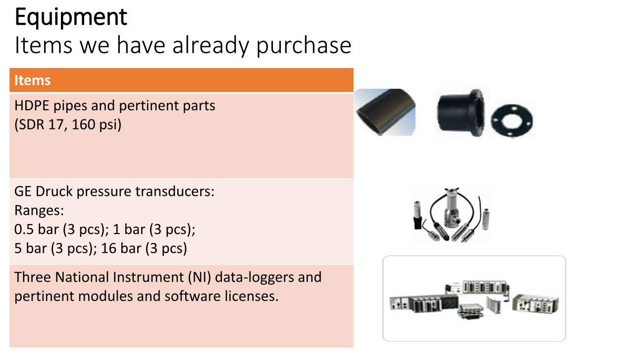
EquipmentItems we have already purchaseItems
HDPE pipes and pertinent parts (SDR 17, 160 psi)
GE Druck pressure transducers:Ranges: 0.5 bar (3 pcs); 1 bar (3 pcs);5 bar (3 pcs); 16 bar (3 pcs)
Three National Instrument (NI) data-loggers and pertinent modules and software licenses.

EquipmentItems we have already purchaseItems
Three rugged laptops for DAQ in lab and field
Four pelican cases for transporting equipment
High frequency ICP® pressure sensor6.89bar, 3pcs13.8 bar, 3pcs34.5bar, 3pcsand pertinent parts

EquipmentItems we have already purchaseItems
Pneumatic pressure calibratorRanges:7 bar (1 pc); 20 bar (1 pc)
Knaack boxes for storage of equipment in the fieldSolenoid valve-820 series,BIBUS-Shanghai Co.1/8 and 1/4 , 3/4 and 1/2
Benthowave custom BII-7531BII-6010 (Impedance Matching)BII-5061 (Linear Power Amplifier)

Proposed Layout in the Lab

Pipe setup in the laboratory
Start: 31-May- 2017
Expected day to finish: 30- June-2017
• Total length: 139.00 m
• Material: HDPE
• Diameter: 3 inch
• Design flow rate: 4.5L/s
• Working pressure: 30m

Field Test• 426m Ductile iron pipe
• Mainly ductile iron.
• PRV is fully open.
• Measurement in 2 fire hydrants
• Timing and Synchronization in NI LabVIEW
Test conducted:• Transient test on 25 May 2017o Noise measuremento Ball valve-Transient Testo Solenoid valve- Transient Test

NI Location

Video of slow closure- Ball valve test in Hydr 2

Video of Solenoid valve test in Hydr 2

Transient test: Manual valve closure
S1 S2 S3R1
R2
R3
1. Three slow closure, fully open: S1, S2, S32. Three fast closure, not fully open: F1, F2, F33. Three fast closure, Open and close: R1, R2, R3
F1 F3F2

Manual S1no filtering
Manual S2no filtering
Manual S3no filtering

• Filtered slow closure data, filter window=1 second
• 1000 data point
Manual S1filtering
Manual S2filtering
Manual S3filtering

Manual F1no filtering
Manual F2no filtering
Manual F3no filtering

• Filtered data, filter width 1 second
Manual F1filtering
Manual F2filtering
Manual F3filtering

Dt = 0.138s
Dt = 0.131s
Wave speed = 856m/s
Manual R1no filtering
Manual R2no filtering
Manual R3no filtering

Transient test: electromagnetic valve
1. Three fast closure, wait for steady state: S1, S2, S3
2. Three fast closure, open and close (50ms): F1, F2, F3
3. Three fast closure, open and close (100ms): R1, R2, R3
S1 S2 S3F1 F2
F3 R1 R2
R3

Electro-valve S1 no filtering
Electro-valve S2 no filtering
Electro-valve S3 no filtering

• Filtered result: window 1 second
• 1000 data point
Electro-valve S1 filtering
Electro-valve S2 filtering
Electro-valve S2 filtering

Electro-valve F1 no filtering
Electro-valve F2 no filtering
Electro-valve F3 no filtering

Electro-valve R1 no filtering
Electro-valve R2 no filtering
Electro-valve R3 no filtering

Proposed hydrant setup- Field
Threaded support mounted
on the ground
UNIK pressure transducer
Fire hydrant
Valve
Internal
diameter 3 inch
Valve Valve

Noise measurement Analysis
From t=1800s to t=1825s
Entire signal
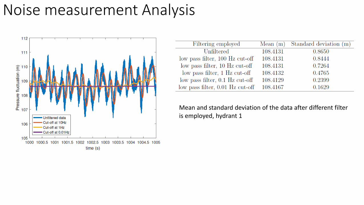
Mean and standard deviation of the data after different filter is employed, hydrant 1
Noise measurement Analysis
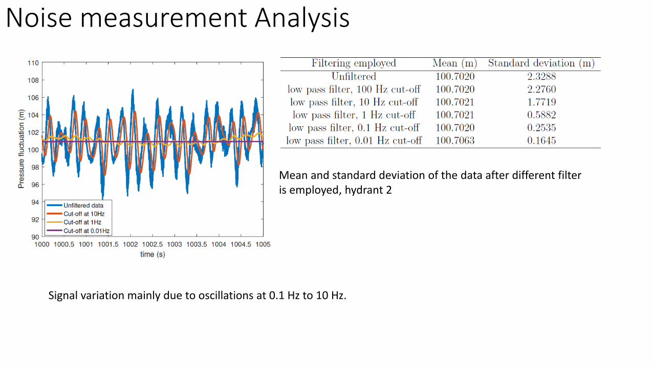
Mean and standard deviation of the data after different filter is employed, hydrant 2
Noise measurement Analysis
Signal variation mainly due to oscillations at 0.1 Hz to 10 Hz.

Noise measurement result
a=L/T=115.109/0.015=7674m/s (!!?). Mistakes? Or are we measuring standing waves?

time lags corresponding to maximum R1 second sections 30 second sections one minute sections five minute sections
Average (second) 0.01082 0.01595 0.01606 0.01600
st dev (second) 0.00741 0.00213 0.00204 0.00163
Coefficient of variation 68.5% 13.3% 12.7% 10.2%
Min (second) 0 0.012 0.012 0.014
Max (second) 0.033 0.02 0.02 0.018
Range of wavespeed = 3488 m/s to infinity
Noise measurement result

-7/3
-7/3-7/3
With Pressure Reducing Valve
Without Pressure Reducing Valve
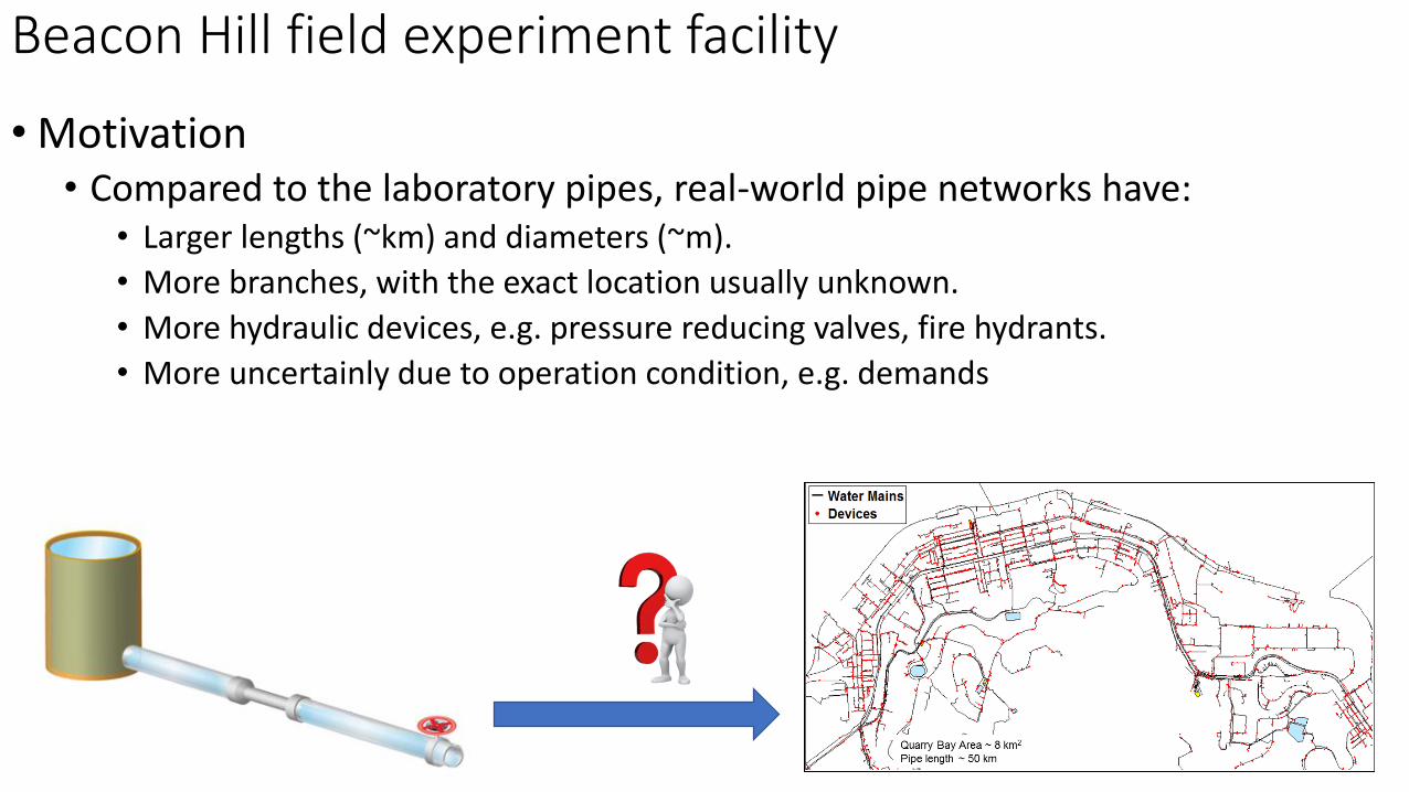
• Motivation• Compared to the laboratory pipes, real-world pipe networks have:
• Larger lengths (~km) and diameters (~m).
• More branches, with the exact location usually unknown.
• More hydraulic devices, e.g. pressure reducing valves, fire hydrants.
• More uncertainly due to operation condition, e.g. demands
Beacon Hill field experiment facility

Beacon Hill field experiment facility
• The facility provides an opportunity to:• Test in-pipe wave propagation in a realistic yet controlled conditions.
• The pipelines replicate closely the HK water supply pipelines.
• System configurations can be modified, e.g. adding a hydrant, without disturbing the water supply of the public.
• Build up the knowledge on field testing of pipe transients in HK.
Location of the proposed field experiment facility

Basic information:
• Length of the pipe (L): 139m.
• Pipe diameter: 4 inch
• Pipe material: PVC.
• Estimated upstream head: 60m
• Transducers, leaks, blocks or other devices can be installed at the removable sections if needed.
Tests to be performed:
• Leak off tests with low frequency waves (LFW, < 5 kHz).
• Effect of blockages on LFW
• Effect of hydrants, both fully and partially filled with water, on LFW propagation.
• Effect of PRV to LFW propagation.
Water supply
Water
supply
Water
supply
Beacon Hill Intermediate Level
Fresh Water Service Reservoir
Flow
Hydrant
Hydrant
Gate valve
Air release valve
Existing training facility
Existing Sea
Water ServiceReservoir
Side discharge to
U-channel
Removable section
Exis
ting U
-channel
Ball valve
Tapping point:
rising main to ground level
Drain point
EM Flowmeter
Pressure reducing valve
Legend
Existing underground fresh water pipes
Pipes proposed by Smart UWSS on the ground
Simulated leak:
Ball valve
Flow control
valves
To U-channel

• Summary• The construction of a 139m HDPE pipe system is undertaken.
• Several field measurements are conducted during four months.
• Future work• Lab
• Noise measurement in new lab setup
• Use Benthowave to generate low frequency signals
• Field• Synchronization of NI data loggers
• More noise measurements
• Transient tests with the new hydrant setup
• Finalize the design of the Beacon Hill field experiment facility
Summary and Future Work

Back up

Field test pipe in Ngau Tau Kok
93.633m1.790m
2.708m87.195m
24.116m
11
.43
8m
51.789m
12.107m51.213m53.247m
1.764m
8.794m
3.352m 1.528m
4.451m
2.911m
2.926m
2.809m2.502m
13.879m3.746m
8.456m
3.565m
1.405m
1.700m
1.628m
1.800m
5.336m
5.5
54
m
4.9
09
m
3.519m
9.6
95
m
4.6
05
m
Junction to external network
Legend:
Fire hydrantValve
Normally closed valve
Dead end
Flowmeter Pressure reducing valve
Pipe leading to consumers
PH1597
PH1598
PH1601
Ductile iron pipe: 200mm diameterDuctile iron pipe: 150mm diameter
NI location