Embed Size (px)
Citation preview
ELSEVIER 1999/05/05 Prn:27/09/1999; 15:22 F:AIJ1675.tex; VTEX/PS p. 1 (32-149)
Artificial Intelligence 00 (1999) 1–53
Experiences with aninteractive museum tour-guide robot
Wolfram Burgarda, Armin B. Cremersa, Dieter Foxb, Dirk Hähnela,Gerhard Lakemeyerc, Dirk Schulza, Walter Steinera, Sebastian Thrunb,∗
a Computer Science Department III, University of Bonn, Germanyb Computer Science Department and Robotics Institute, Carnegie Mellon University,
Pittsburgh, PA 15213, USAc Computer Science Department V, Technological University of Aachen, Germany
Received 30 June 1998
Abstract
This article describes the software architecture of an autonomous, interactive tour-guide robot.It presents a modular and distributed software architecture, which integrates localization, mapping,collision avoidance, planning, and various modules concerned with user interaction and Web-basedtelepresence. At its heart, the software approach relies on probabilistic computation, on-line learning,and any-time algorithms. It enables robots to operate safely, reliably, and at high speeds in highlydynamic environments, and does not require any modifications of the environment to aid the robot’soperation. Special emphasis is placed on the design of interactive capabilities that appeal to people’sintuition. The interface provides new means for human-robot interaction with crowds of people inpublic places, and it also provides people all around the world with the ability to establish a “virtualtelepresence” using the Web. To illustrate our approach, results are reported obtained in mid-1997,when our robot “RHINO” was deployed for a period of six days in a densely populated museum.The empirical results demonstrate reliable operation in public environments. The robot successfullyraised the museum’s attendance by more than 50%. In addition, thousands of people all over theworld controlled the robot through the Web. We conjecture that these innovations transcend to amuch larger range of application domains for service robots. 1999 Elsevier Science B.V. All rightsreserved.
Keywords:Mobile robotics; Probabilistic reasoning; Localization; Mapping; Planning; Collision avoidance;Logic; Human robot interaction; Machine learning; Entertainment
∗ Corresponding author. Email: [email protected].
0004-3702/99/$ – see front matter 1999 Elsevier Science B.V. All rights reserved.PII: S0004-3702(99)00070-3
ELSEVIER 1999/05/05 Prn:27/09/1999; 15:22 F:AIJ1675.tex; VTEX/PS p. 2 (149-212)
2 W. Burgard et al. / Artificial Intelligence 00 (1999) 1–53
1. Introduction
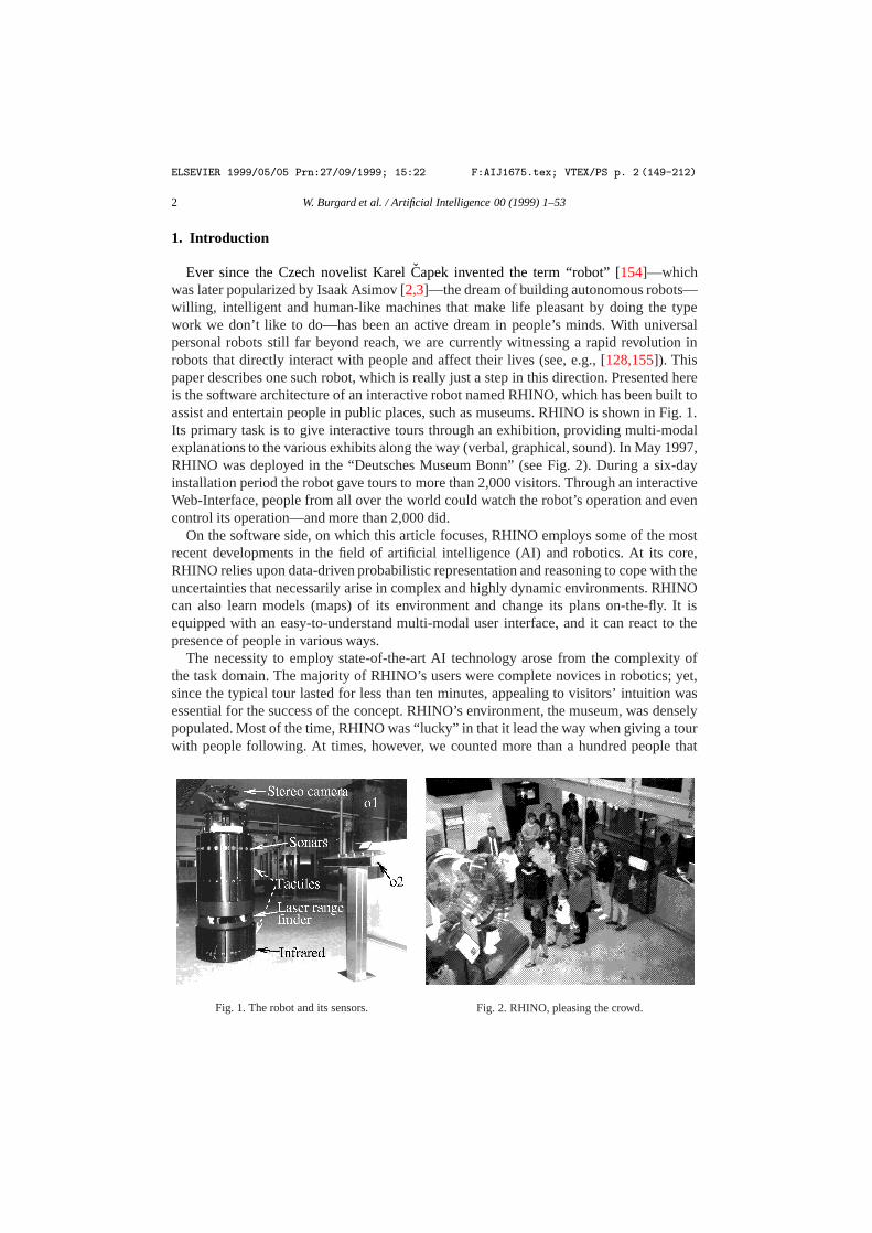
Ever since the Czech novelist KarelCapek invented the term “robot” [154]—whichwas later popularized by Isaak Asimov [2,3]—the dream of building autonomous robots—willing, intelligent and human-like machines that make life pleasant by doing the typework we don’t like to do—has been an active dream in people’s minds. With universalpersonal robots still far beyond reach, we are currently witnessing a rapid revolution inrobots that directly interact with people and affect their lives (see, e.g., [128,155]). Thispaper describes one such robot, which is really just a step in this direction. Presented hereis the software architecture of an interactive robot named RHINO, which has been built toassist and entertain people in public places, such as museums. RHINO is shown in Fig. 1.Its primary task is to give interactive tours through an exhibition, providing multi-modalexplanations to the various exhibits along the way (verbal, graphical, sound). In May 1997,RHINO was deployed in the “Deutsches Museum Bonn” (see Fig. 2). During a six-dayinstallation period the robot gave tours to more than 2,000 visitors. Through an interactiveWeb-Interface, people from all over the world could watch the robot’s operation and evencontrol its operation—and more than 2,000 did.
On the software side, on which this article focuses, RHINO employs some of the mostrecent developments in the field of artificial intelligence (AI) and robotics. At its core,RHINO relies upon data-driven probabilistic representation and reasoning to cope with theuncertainties that necessarily arise in complex and highly dynamic environments. RHINOcan also learn models (maps) of its environment and change its plans on-the-fly. It isequipped with an easy-to-understand multi-modal user interface, and it can react to thepresence of people in various ways.
The necessity to employ state-of-the-art AI technology arose from the complexity ofthe task domain. The majority of RHINO’s users were complete novices in robotics; yet,since the typical tour lasted for less than ten minutes, appealing to visitors’ intuition wasessential for the success of the concept. RHINO’s environment, the museum, was denselypopulated. Most of the time, RHINO was “lucky” in that it lead the way when giving a tourwith people following. At times, however, we counted more than a hundred people that
Fig. 1. The robot and its sensors. Fig. 2. RHINO, pleasing the crowd.

ELSEVIER 1999/05/05 Prn:27/09/1999; 15:22 F:AIJ1675.tex; VTEX/PS p. 3 (212-280)
W. Burgard et al. / Artificial Intelligence 00 (1999) 1–53 3
surrounded the robot from all sides, making it difficult for the robot to reach the exhibitsas planned while not losing track of its orientation. The museum itself, its geometry andits exhibits, posed further challenges on the software. While there were several narrowpassages in the environment in which accurate motion control was essential, most of themuseum consisted of wide open spaces that, to a large extent, lacked the necessary structurefor the robot to orient itself. One of the key constraints was the necessity to avoid collisionswith obstacles at all costs, humans and exhibits alike. Many of the obstacles, however, wereliterally “invisible”, i.e., they could physically not be detected with the robot’s sensors. Theinability to sense certain obstacles was not necessarily due to the lack of an appropriatesensor suite—in fact, RHINO used four different sensor systems, ranging from laser rangefinders, sonar, and active infrared sensors to touch-sensitive panels—rather, it was thenature of the obstacles. For example, many exhibits were protected by glass cases, whosevery purpose implied that they were not detectable by light-based sensors such as cameras,laser, or infrared, and whose smoothness made it impossible to detect them reliably evenwith sonar. Other exhibits were placed on solid metal plates, many of which were belowthe range of our lowest sensors.
Not all objects in the museum were static. In particular, the museum provided stoolsfor the visitors to rest, and people tended to leave them behind at random places, usuallyclose to exhibits. The problem of safe navigation was made more difficult by the speedrequirements in the museum. To be interesting to the people, the robot had to move atwalking speed whenever possible. At speeds of up to 80 cm/sec, the inertia of the robotis significant; turning or stopping on the spot is impossible. Lastly, some of the userswere not at all cooperative, imposing further difficulties for the software design. Oftenmuseum visitors tried to “challenge” the robot. For example, by permanently blocking itsway, they sometimes sought to make the robot leave the designated exhibition area towardsother parts of the museum, where several unmapped and undetectable hazards existed(including a staircase). We quickly learned that one cannot necessarily expect humansto be cooperative, so the safety of the system may not depend on specific behavioralrequirements on the side of the users. On the other hand, people are thrilled if robotsinteract with them—just like they are if people interact with them. Thus, a primarycomponent of a successful tour-guide is the ability to notice the presence of people, and tointeract with them in a meaningful, appealing way. In fact, when we interviewed museumvisitors, most of them assigned more weight to the robot’s interactive capabilities than toits ability to navigate.
These challenges mandated the development of a collection of new, innovative softwaresolutions. Our past work (e.g., [16,149]) focused primarily on office navigation—whichinvolved moving through static corridors and into offices with well-detectable obstaclesand cooperative people—where many of the difficulties simply did not exist. Many ofthe assumptions underlying this work do not apply in populated public places, such as amuseum. As a result, we had to develop several new techniques and, more importantly,changed our view on several well-established methodologies in the field.
For example, most successful mobile robot architectures employ sensor-based, reactivemethods for real-time collision avoidance [85]. The typical paradigm is to consider a shorttime window of past sensor readings when setting the speed and final motion directionof the robot. Of course, the purely sensor-based approach is inappropriate if obstacles

ELSEVIER 1999/05/05 Prn:27/09/1999; 15:22 F:AIJ1675.tex; VTEX/PS p. 4 (280-327)
4 W. Burgard et al. / Artificial Intelligence 00 (1999) 1–53
cannot be sensed. RHINO employs a hybrid approach, which incorporates a map of theenvironment in addition to sensor readings. The map contains “invisible” obstacles andhazards such as staircases. For the map to be useful, however, the robot has to knowwhere it is with high accuracy. RHINO employs an efficient, fine-grain variant of Markovlocalization, capable of tracking the robot’s position with high accuracy. Localizationproved more difficult in the museum than in our office environment. Markov localizationrelies on the assumption that the robot’s location is the only state in the world. However,large numbers of people that followed the robot closely, thereby blocking most of itssensors constantly violate this assumption. As demonstrated here and elsewhere [53], thebasic Markov localization algorithm would have failed under such conditions. RHINOemploys an extended localization method that filters out corrupted sensor readings. Thisapproach, described in detail below, considers only sensor data that reduce the uncertaintyof the robot during localization. As a result, the robot pays only attention to sensor datathat confirms its current belief while ignoring all other data. While this approach criticallydeparts from the basic Markov approach, it makes localization succeed in this highly non-Markovian environment.
Most navigation approaches either rely on a fixed, pre-given map of the environment,or learn such a map by themselves. Neither of these two options was appropriate—a fixed map would have made it impossible to navigate successfully when obstaclesblocked the robot’s path persistently (such as the stools). A pure learning approach, whichwas used successfully in a prototype tour-guide robot that was previously installed inour university building [149], was inappropriate since the robot was unable to map thoseinvisible obstacles. RHINO’s software integrates both types maps, using a hand-craftedCAD map as a starting point and a map learned on-the-fly from sensor data. To cope withchanging maps, RHINO uses an efficient motion planner that can quickly react to changesin the map.
Finally, a key ingredient of any robot that interacts with people in public places isits interactive component. To interact with people, a method for finding people is calledfor. Unfortunately, sensor differencing (e.g., image differencing) is inapplicable since ittypically assumes that the people move and the robot doesn’t—in our case, the robot wasalmost always in motion, while people often didn’t move. Thus, RHINO finds people bycomparing the map with its range measurements, using the inverse of the filter describedabove. The robot then invokes a series of means that inform people of the robot’s intentionsand goals. RHINO also possesses two user interfaces, one for visitors and one for Web-users, which are designed to be simple enough for people to operate even without priorexposure to robotics.
This article provides an overview of the major components of RHINO’s softwarearchitecture. As this description of the museum suggests, operating a robot in publicenvironments as complex (and dangerous) as it poses research challenges that go beyondmany of those found in most office environments. To cope with them, this paper describesa collection of algorithms which provide the robot with some unique features, suchas its ability navigate smoothly and safely at high speed, to determine its location inan unmodified environment and populated, the ability to quickly find detours if pathsare blocked, and the ability to engage and interact with people. We believe that thesecharacteristics are prototypical for a large variety of application domains for mobile robots,
ELSEVIER 1999/05/05 Prn:27/09/1999; 15:22 F:AIJ1675.tex; VTEX/PS p. 5 (327-447)
W. Burgard et al. / Artificial Intelligence 00 (1999) 1–53 5
and conjecture that virtually all of the technology described in this paper can be applied toa much larger variety of tasks.
2. Architectural overview
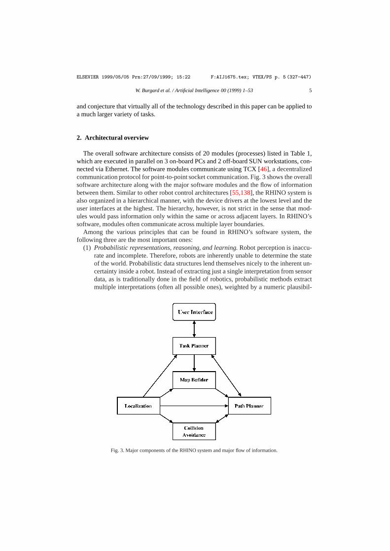
The overall software architecture consists of 20 modules (processes) listed in Table 1,which are executed in parallel on 3 on-board PCs and 2 off-board SUN workstations, con-nected via Ethernet. The software modules communicate using TCX [46], a decentralizedcommunication protocol for point-to-point socket communication. Fig. 3 shows the overallsoftware architecture along with the major software modules and the flow of informationbetween them. Similar to other robot control architectures [55,138], the RHINO system isalso organized in a hierarchical manner, with the device drivers at the lowest level and theuser interfaces at the highest. The hierarchy, however, is not strict in the sense that mod-ules would pass information only within the same or across adjacent layers. In RHINO’ssoftware, modules often communicate across multiple layer boundaries.
Among the various principles that can be found in RHINO’s software system, thefollowing three are the most important ones:
(1) Probabilistic representations, reasoning, and learning.Robot perception is inaccu-rate and incomplete. Therefore, robots are inherently unable to determine the stateof the world. Probabilistic data structures lend themselves nicely to the inherent un-certainty inside a robot. Instead of extracting just a single interpretation from sensordata, as is traditionally done in the field of robotics, probabilistic methods extractmultiple interpretations (often all possible ones), weighted by a numeric plausibil-
Fig. 3. Major components of the RHINO system and major flow of information.
ELSEVIER 1999/05/05 Prn:27/09/1999; 15:22 F:AIJ1675.tex; VTEX/PS p. 6 (447-447)
6 W. Burgard et al. / Artificial Intelligence 00 (1999) 1–53
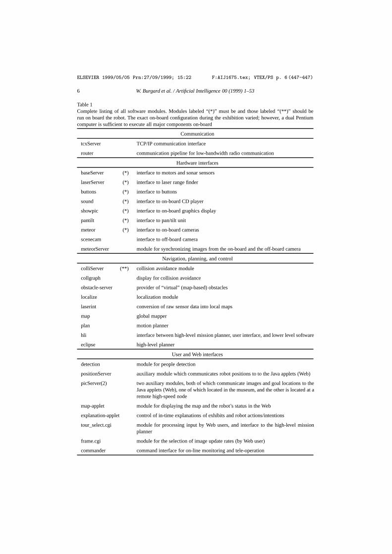
Table 1Complete listing of all software modules. Modules labeled “(*)” must be and those labeled “(**)” should berun on board the robot. The exact on-board configuration during the exhibition varied; however, a dual Pentiumcomputer is sufficient to execute all major components on-board
Communication
tcxServer TCP/IP communication interface
router communication pipeline for low-bandwidth radio communication
Hardware interfaces
baseServer (*) interface to motors and sonar sensors
laserServer (*) interface to laser range finder
buttons (*) interface to buttons
sound (*) interface to on-board CD player
showpic (*) interface to on-board graphics display
pantilt (*) interface to pan/tilt unit
meteor (*) interface to on-board cameras
scenecam interface to off-board camera
meteorServer module for synchronizing images from the on-board and the off-board camera
Navigation, planning, and control
colliServer (**) collision avoidance module
collgraph display for collision avoidance
obstacle-server provider of “virtual” (map-based) obstacles
localize localization module
laserint conversion of raw sensor data into local maps
map global mapper
plan motion planner
hli interface between high-level mission planner, user interface, and lower level software
eclipse high-level planner
User and Web interfaces
detection module for people detection
positionServer auxiliary module which communicates robot positions to to the Java applets (Web)
picServer(2) two auxiliary modules, both of which communicate images and goal locations to theJava applets (Web), one of which located in the museum, and the other is located at aremote high-speed node
map-applet module for displaying the map and the robot’s status in the Web
explanation-applet control of in-time explanations of exhibits and robot actions/intentions
tour_select.cgi module for processing input by Web users, and interface to the high-level missionplanner
frame.cgi module for the selection of image update rates (by Web user)
commander command interface for on-line monitoring and tele-operation
ELSEVIER 1999/05/05 Prn:27/09/1999; 15:22 F:AIJ1675.tex; VTEX/PS p. 7 (447-520)
W. Burgard et al. / Artificial Intelligence 00 (1999) 1–53 7
ity factor that is expressed as a conditional probability. By considering multiplehypotheses, the robot can deal in a mathematically elegant way with ambiguitiesand uncertainty. In our experience, robots that use probabilistic representations re-cover easier from false beliefs and therefore exhibit more robust behavior. In addi-tion, probability theory provides nice and elegant ways to integrate evidence frommultiple sources over time, and to make optimal decisions under uncertainty. Re-cently, probabilistic methods have been employed in a variety of successful mobilerobots [19,66,74,111,139], for reasons similar to the ones given here.
(2) Resource flexibility. Most of RHINO’s software can adapt to the available compu-tational resources. For example, modules that consume substantial processing time,such as the motion planner or the localization module, can produce results regard-less of the time available for computation. The more processing cycles are available,however, the better or more accurate the result. In RHINO’s software, resource flex-ibility is achieved by two mechanisms: selective data processing and any-time al-gorithms [38,162]. Some modules consider only a subset of the available data, suchas the localization routine. Other modules, such as the motion planning module, canquickly draft initial solutions which are then refined incrementally, so that an answeris available when needed.
(3) Distributed, asynchronous processing with decentralized decision making.RHINO’ssoftware does not possess a centralized clock or a centralized communication mod-ule. Synchronization of different modules is strictly decentral. Time-critical soft-ware (e.g., all device drivers), and software that is important for the safety of therobot (e.g., collision avoidance), are run on the robot’s on-board computers. Higher-level software, such as the task control module, is run on the stationary comput-ers. This software organization has been found to yield robust behavior even in thepresence of unreliable communication links (specifically the radio link which con-nected the on-board and off-board computers) and various other events that cantemporarily delay the message flow or reduce the available computational time. Themodular, decentralized software organization eases the task of software configura-tion. Each module adds a certain competence, but not all modules are required torun the robot. The idea of decentralized, distributed decision making has been atthe core of research on behavior-based robotics over the last decade [1,15,121], buthere modules are typically much lower in complexity (e.g., simple finite state ma-chines).
The remainder of this paper will describe those software modules that were most essentialto RHINO’s success.
3. State estimation
To find its way safely through a populated environment with invisible obstacles, RHINOemploys several methods to estimate its current state. State comprises the robot’s positionand the position of people and obstacles. This section describes RHINO’s approach tolocalization and mapping, both of which use probabilistic estimators for interpreting andintegrating sensor evidence.

ELSEVIER 1999/05/05 Prn:27/09/1999; 15:22 F:AIJ1675.tex; VTEX/PS p. 8 (520-592)
8 W. Burgard et al. / Artificial Intelligence 00 (1999) 1–53
3.1. Localization
At the core of RHINO’s navigation routines is a module that continuously estimates therobot’s position inx-y-θ space, wherex andy are the coordinates of the robot in a 2DCartesian coordinate system andθ is its orientation. RHINO employs a variant ofMarkovlocalization, which is a probabilistic method for robot localization [19,74,111,139,145]. Itsinput is a stream of sensor readings from the robot’s proximity sensors, interleaved with asequence of action commands. Throughout this paper, this sequence will be denoted
d = {o(1), o(2) . . . , o(T )}, (1)
where eacho(t) with t ∈ {1, . . . , T } is either a sensor reading or an action command. Thelocalization module computes, incrementally and in real-time, a probability distributionP(ξ(t)) that expresses the robot’s belief to be at locationξ(t) at timet where eachξ(t) is alocation in the three-dimensionalx-y-θ space.
The robot’s belief at timet is described by the conditional probability
P(ξ(t))= P (ξ |o(1), o(2), . . . , o(t)). (2)
To compute this probability, three aspects have to be discussed: (1) initialization, (2)sensing, and (3) motion. The latter two, sensing and motion, have opposite effects onthe robot’s belief. While sensor readings convey information about the robot’s position,thereby often decreasing the entropy ofP(ξ(t)), actions generally cause a loss ofinformation due to the inaccurate nature of robot motion, and increase the entropy ofP(ξ(t ). The entropy ofP(ξ(t)) will be discussed further below in Section 3.1.6.
3.1.1. InitializationInitially, at time t = 0, P(ξ(0)) reflects the robot’s initial state of knowledge in the
absence of any datad . If the robot’s initial position isξ0 and if it knows exactly whereit is, P(ξ(0)) is initialized with a Dirac distribution
P(ξ(0))={
1, if ξ = ξ0,
0, if ξ 6= ξ0.(3)
If the robot does not know where it is,P(ξ) is initialized with a uniform distribution.Of particular interest in this paper is the latter case, since the robot was often placedsomewhere in the museum without initial knowledge of its position. Thus, the robot had tolocalize itself under global uncertainty, a problem also known asglobal localizationor thekidnapped robot problem[44].
3.1.2. Robot perceptionSuppose at timet , the robot receives a sensor measuremento(t). In RHINO’s localization
module,o(t) is either a laser scan or a sonar scan. This measurement is used to update theinternal belief as to where the robot is, according to the following rule:
P(ξ(t)|o(1), . . . , o(t))= α P (o(t)|ξ(t), o(1), . . . , o(t−1)) P (ξ(t)|o(1), . . . , o(t−1))= α P (o(t)|ξ(t)) P (ξ(t)|o(1), . . . , o(t−1)). (4)

ELSEVIER 1999/05/05 Prn:27/09/1999; 15:22 F:AIJ1675.tex; VTEX/PS p. 9 (592-680)
W. Burgard et al. / Artificial Intelligence 00 (1999) 1–53 9
Hereα is the Bayes normalizer that ensures that the probabilities on the left-hand side of(4) sum up to 1, andP(ξ(t)|o(1), . . . , o(t−1)) is the robot’s belief just before sensingo(t).The first step of the derivation of (4) follows from Bayes rule. The second step rests on thefollowing conditional independence assumption, also calledMarkov assumption:
P(o(t)|ξ(t), o(1), . . . , o(t−1))= P (o(t)|ξ(t)). (5)
This conditional independence assumption states that if the robot’s location at timet isknown, knowledge of past sensor readingso(1), . . . , o(t−1) do not convey any informationrelevant to the prediction ofo(t). In other words, the Markov property assumes thereis no state in the environment other than the robot’s own location. In most realisticenvironments such as the museum, this assumption is violated; for example, peopleoften block the robot’s sensors for multiple time steps, which makes sensor readingsconditionally dependent even if the exact robot location is known. Section 3.1.6 willexplicitly address this problem. For now, the Markov assumption will be adopted, as itis mathematically convenient and as it justifies a simple, incremental update rule.
The update equation (4) relies on the probabilityP(o(t)|ξ(t)) of observingo(t) at locationξ(t), which henceforth is called theperceptual model. The perceptual model does notdepend ont ; thus, for the reader’s convenience we will omit the superscript(t) and writeP(o|ξ) instead.
RHINO uses its proximity sensors (sonars, lasers) for localization. Its perceptual modelis obtained using a generic noise model of the robot’s sensors along with a map of theenvironment. More specifically,P(o|ξ) is computed in two steps:
P(o|ξ)= P(o|dist(ξ)), (6)
Here the functiondist:Ξ → R computes theexpectedmeasurement that a noise-freesensor would obtain in a stationary environment. The value ofdist(ξ) is computed byray tracing in a map of the robot’s environment. The remaining probability,P(o|dist(ξ)),models thenoisein perception. It is learned from data. The left diagram in Fig. 4 showsthe empirical distribution ofP(o|dist(ξ)) obtained from 11× 106 measurements; here“expected distance” refers todist(ξ), “measured distance” refers too, and the vertical axisplots the probabilityP(o|dist(ξ)). In RHINO’s software,P(o|dist(ξ)) is approximatedby a mixture of a Gaussian, a geometric, and a Dirac distribution, as shown in the rightdiagram in Fig. 4. The coefficients of these distribution are learned from data, using themaximum likelihood estimator [8].
Fig. 5 illustrates the perceptual model in practice. An example laser range scan is shownin Fig. 5(a). Fig. 5(b) shows, for each positionξ , the likelihoodP(o|ξ) of this specificrange scan in a pre-supplied map (projected into 2D). As is easy to be seen,P(o|ξ) is highin the main corridor, whereas it is low in the rooms.
In our implementation, the parameters of the perceptual model are obtained throughmaximum likelihood estimation from data, i.e., pairs of measurementso and “true”distancesdist(ξ). Since such data is difficult to obtain—it requires knowledge of the exactrobot location, a bootstrapping algorithm was used to automatically derive position data.More specifically, our approach relies with position labels derived using an approximateperpetual model, and used these approximate positions to optimize the model parameters.Once the model parameters have been fit, new position labels are computed using the

ELSEVIER 1999/05/05 Prn:27/09/1999; 15:22 F:AIJ1675.tex; VTEX/PS p. 10 (680-723)
10 W. Burgard et al. / Artificial Intelligence 00 (1999) 1–53
Fig. 4. The conditional probabilityP(o|dist(ξ)) obtained from 11,000,000 laser measurements (left) and itsapproximation using a mixture of a Gaussian, a uniform and a Dirac density (right).
(a) (b)
Fig. 5. Probabilistic model of perception: (a) Laser range scan, projected into a previously acquired map. (b)The probabilityP(o|ξ), evaluated for all positionsξ and projected into the map (shown in grey). The darker aposition, the largerP(o|ξ).
improved perceptual model. This approach is iterated in an EM-like fashion [40], leadingto increasingly better data fits. Notice that this approach bears close similarity to a richbody on research on learning from labeled and unlabeled data [9,24,25,109,113,132], andis commonly used in other data-intense fields such as speech recognition [156]. As aresult, our approach can effortlessly use millions of data items gathered during everydayoperation, for building a highly accurate perceptual model.
3.1.3. Robot motionMotion changes the location of the robot. Ifo(t) is a motion command, the robot’s belief
changes according to the following rule:
P(ξ(t+1)|o(1), . . . , o(t))=∫P(ξ(t+1)|ξ(t), o(1), . . . , o(t))P (ξ(t)|o(1), . . . , o(t))dξ(t)
=∫P(ξ(t+1)|ξ(t), o(t))P (ξ(t)|o(1), . . . , o(t−1))dξ(t). (7)
ELSEVIER 1999/05/05 Prn:27/09/1999; 15:22 F:AIJ1675.tex; VTEX/PS p. 11 (723-791)
W. Burgard et al. / Artificial Intelligence 00 (1999) 1–53 11
(a) (b)
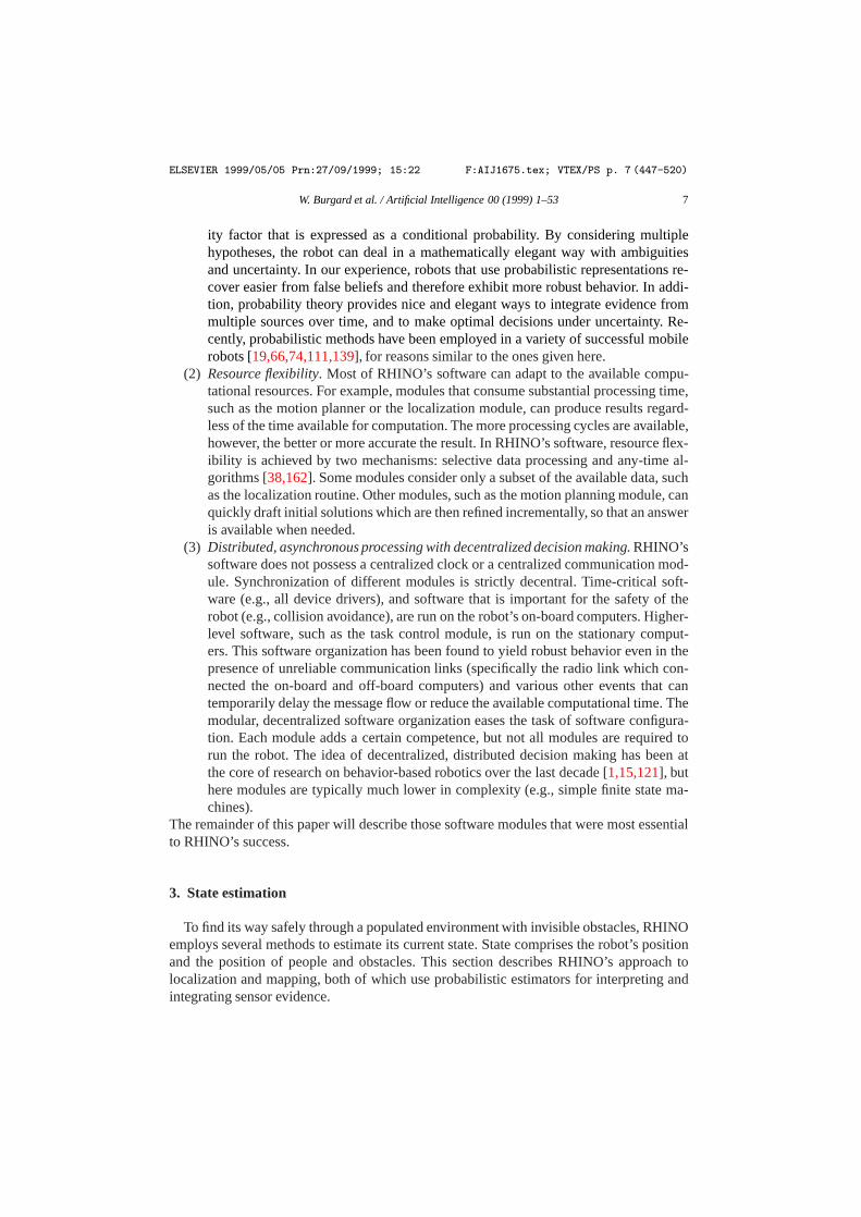
Fig. 6. Probabilistic model of robot motion: Accumulated uncertainty after moving (a) 40 meter, (b) 80 meter.
This update rule is incremental, just like the perceptual update rule (4). The first step in itsderivation is obtained using the Theorem of total probability, and the second step is basedon a similar Markov assumption as the one above:
P(ξ(t+1)|ξ(t), o(t))= P (ξ(t+1)|ξ(t), o(1), . . . , o(t)). (8)
In fact, both Markov assumptions described in this section are consequences of a singleone, which states that the location of the robot is the only state in the environment.
Eq. (7) relies onP(ξ(t+1)|ξ(t), o(t)), which is a probabilistickinematic model of robotmotion. Since the motion model does not depend ont , we will henceforth denote itby P(ξ |ξ ′, o). In our implementation,P(ξ |ξ ′, o) is realized using a mixture of twoindependent, zero-centered distributions, which model rotational and translational error,respectively [19,150]. The width of these distributions are proportional to the length ofthe motion command. Fig. 6 illustrates RHINO’s motion model for two example motioncommands. Shown there are “banana-shaped” distributionsP(ξ |ξ ′, o), which result ifthe robot starts atξ ′ and executes the motion commands specified in the figure caption.Both distributions are of course three-dimensional (inx-y-θ -space); Fig. 6 shows their 2Dprojections intox-y-space.
3.1.4. Grid-based Markov localizationThe generic, incremental Markov localization algorithm is depicted in Table 2. Here
the time index is omitted, to emphasize the incremental nature of the algorithm. Inexperimental tests this method has been demonstrated to localize the robot reliably instatic environments even if it does not have any prior knowledge about the robot’s position[19,20,51].
Recently, different variants of Markov localization have been developed [19,74,111,139].These methods can be roughly distinguished by the nature of the state space representa-tion. Virtually all published implementations of Markov localization, with the more recentexception of [39,48], are based on coarse-grained representations of space, often with aspatial resolution of less than one meter and an angular resolution of 90 degrees. For ex-ample, in [74,111,139] Markov localization is used for landmark-based corridor navigationand the state space is organized according to the topological structure of the environment.Unfortunately, coarse-grained, topological representations are insufficient for navigatingin the close vicinity of invisible (but known) obstacles, such as the glass cases described
ELSEVIER 1999/05/05 Prn:27/09/1999; 15:22 F:AIJ1675.tex; VTEX/PS p. 12 (791-907)
12 W. Burgard et al. / Artificial Intelligence 00 (1999) 1–53
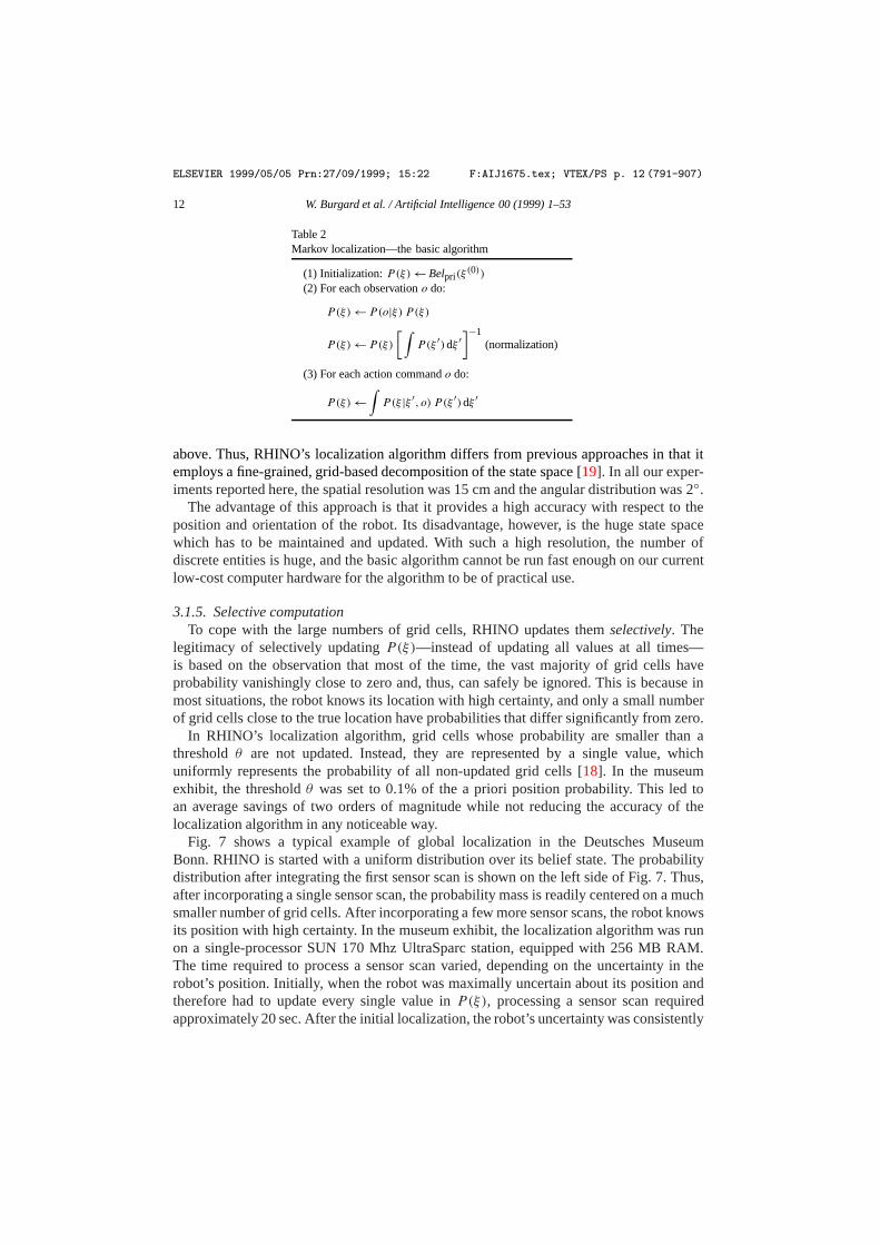
Table 2Markov localization—the basic algorithm
(1) Initialization:P(ξ)← Belpri(ξ(0))
(2) For each observationo do:
P(ξ)← P(o|ξ) P (ξ)
P (ξ)← P(ξ)
[∫P(ξ ′)dξ ′
]−1(normalization)
(3) For each action commando do:
P(ξ)←∫P(ξ |ξ ′, o) P (ξ ′)dξ ′
above. Thus, RHINO’s localization algorithm differs from previous approaches in that itemploys a fine-grained, grid-based decomposition of the state space [19]. In all our exper-iments reported here, the spatial resolution was 15 cm and the angular distribution was 2◦.
The advantage of this approach is that it provides a high accuracy with respect to theposition and orientation of the robot. Its disadvantage, however, is the huge state spacewhich has to be maintained and updated. With such a high resolution, the number ofdiscrete entities is huge, and the basic algorithm cannot be run fast enough on our currentlow-cost computer hardware for the algorithm to be of practical use.
3.1.5. Selective computationTo cope with the large numbers of grid cells, RHINO updates themselectively. The
legitimacy of selectively updatingP(ξ)—instead of updating all values at all times—is based on the observation that most of the time, the vast majority of grid cells haveprobability vanishingly close to zero and, thus, can safely be ignored. This is because inmost situations, the robot knows its location with high certainty, and only a small numberof grid cells close to the true location have probabilities that differ significantly from zero.
In RHINO’s localization algorithm, grid cells whose probability are smaller than athresholdθ are not updated. Instead, they are represented by a single value, whichuniformly represents the probability of all non-updated grid cells [18]. In the museumexhibit, the thresholdθ was set to 0.1% of the a priori position probability. This led toan average savings of two orders of magnitude while not reducing the accuracy of thelocalization algorithm in any noticeable way.
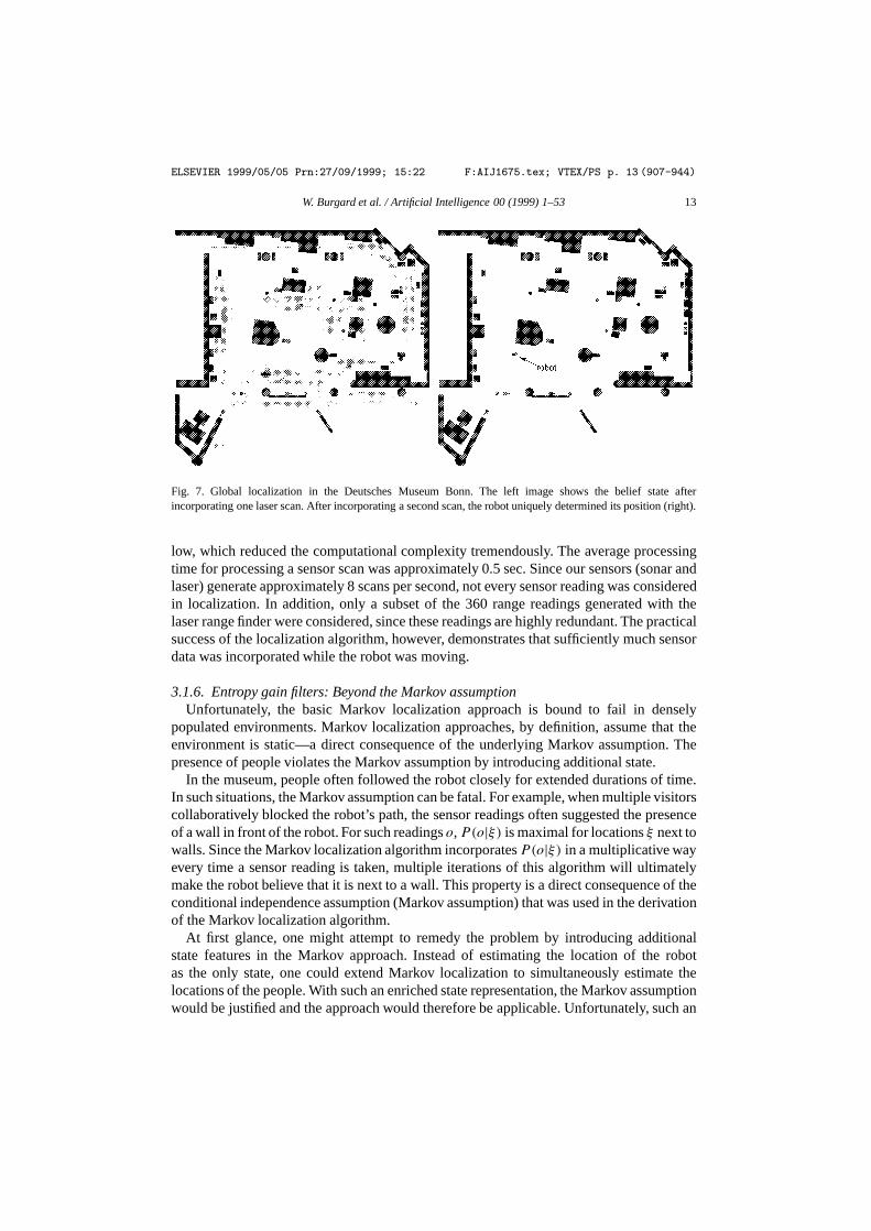
Fig. 7 shows a typical example of global localization in the Deutsches MuseumBonn. RHINO is started with a uniform distribution over its belief state. The probabilitydistribution after integrating the first sensor scan is shown on the left side of Fig. 7. Thus,after incorporating a single sensor scan, the probability mass is readily centered on a muchsmaller number of grid cells. After incorporating a few more sensor scans, the robot knowsits position with high certainty. In the museum exhibit, the localization algorithm was runon a single-processor SUN 170 Mhz UltraSparc station, equipped with 256 MB RAM.The time required to process a sensor scan varied, depending on the uncertainty in therobot’s position. Initially, when the robot was maximally uncertain about its position andtherefore had to update every single value inP(ξ), processing a sensor scan requiredapproximately 20 sec. After the initial localization, the robot’s uncertainty was consistently
ELSEVIER 1999/05/05 Prn:27/09/1999; 15:22 F:AIJ1675.tex; VTEX/PS p. 13 (907-944)
W. Burgard et al. / Artificial Intelligence 00 (1999) 1–53 13
Fig. 7. Global localization in the Deutsches Museum Bonn. The left image shows the belief state afterincorporating one laser scan. After incorporating a second scan, the robot uniquely determined its position (right).
low, which reduced the computational complexity tremendously. The average processingtime for processing a sensor scan was approximately 0.5 sec. Since our sensors (sonar andlaser) generate approximately 8 scans per second, not every sensor reading was consideredin localization. In addition, only a subset of the 360 range readings generated with thelaser range finder were considered, since these readings are highly redundant. The practicalsuccess of the localization algorithm, however, demonstrates that sufficiently much sensordata was incorporated while the robot was moving.
3.1.6. Entropy gain filters: Beyond the Markov assumptionUnfortunately, the basic Markov localization approach is bound to fail in densely
populated environments. Markov localization approaches, by definition, assume that theenvironment is static—a direct consequence of the underlying Markov assumption. Thepresence of people violates the Markov assumption by introducing additional state.
In the museum, people often followed the robot closely for extended durations of time.In such situations, the Markov assumption can be fatal. For example, when multiple visitorscollaboratively blocked the robot’s path, the sensor readings often suggested the presenceof a wall in front of the robot. For such readingso,P(o|ξ) is maximal for locationsξ next towalls. Since the Markov localization algorithm incorporatesP(o|ξ) in a multiplicative wayevery time a sensor reading is taken, multiple iterations of this algorithm will ultimatelymake the robot believe that it is next to a wall. This property is a direct consequence of theconditional independence assumption (Markov assumption) that was used in the derivationof the Markov localization algorithm.
At first glance, one might attempt to remedy the problem by introducing additionalstate features in the Markov approach. Instead of estimating the location of the robotas the only state, one could extend Markov localization to simultaneously estimate thelocations of the people. With such an enriched state representation, the Markov assumptionwould be justified and the approach would therefore be applicable. Unfortunately, such an

ELSEVIER 1999/05/05 Prn:27/09/1999; 15:22 F:AIJ1675.tex; VTEX/PS p. 14 (944-1050)
14 W. Burgard et al. / Artificial Intelligence 00 (1999) 1–53
extension is computationally expensive, since the computational and memory complexityincreases exponentially in the number of state variables. In addition, such an approachrequires probabilistic models of the behavior of the various non-stationary obstacles, suchas humans, which may be difficult to obtain.
In our approach, we pursued a different line of thought: filtering. The idea is to sortsensor readings into two buckets, one that corresponds to known obstacles such as walls,and one that corresponds to dynamic obstacles such as humans. Only the former readingsare incorporated into the position estimation, whereas the latter ones are simply discarded.The filtering approach does not explicitly estimate the full state of the environment; rather,it reduces the damaging effect that arises from state other than the robot’s location.
The specific filter used in our implementation is calledentropy gain filter[53] and worksas follows. TheentropyH(P) of a distributionP is defined by [23]
H(P)=−∫P(ξ) logP(ξ)dξ. (9)
Entropy is a measure of uncertainty: The larger the entropy, the higher the robot’suncertainty as to where it is.Entropy gainmeasures the relative change of entropy uponincorporating a sensor reading intoP . More specifically, leto denote a sensor scan, andlet oi denote an individual component of the scan (i.e., a single range measurement). Theentropy gain of a probability distributionP with respect to a sensor measurementoi isdefined as:
1H(P |oi) :=H(P(ξ(t)|o(t)i )
)−H (P(ξ(t−1))). (10)
Entropy gain measures the change of certainty. A positive entropy gain indicates thatafter incorporatingoi , the robot is less certain about its position. A negative entropy gainindicates an increase in certainty upon incorporatingoi .
RHINO’s entropy gain filterfilters out sensor measurements that, if used, woulddecreasethe robot’s certainty. This is achieved by considering only thoseoi for which1H(P |oi) 6 0. The entropy gain filter makes robot perception highly selective, in thatonly sensor readings are considered that confirm the robot’s current belief. The resultingapproach does not comply with the original Markov assumption.
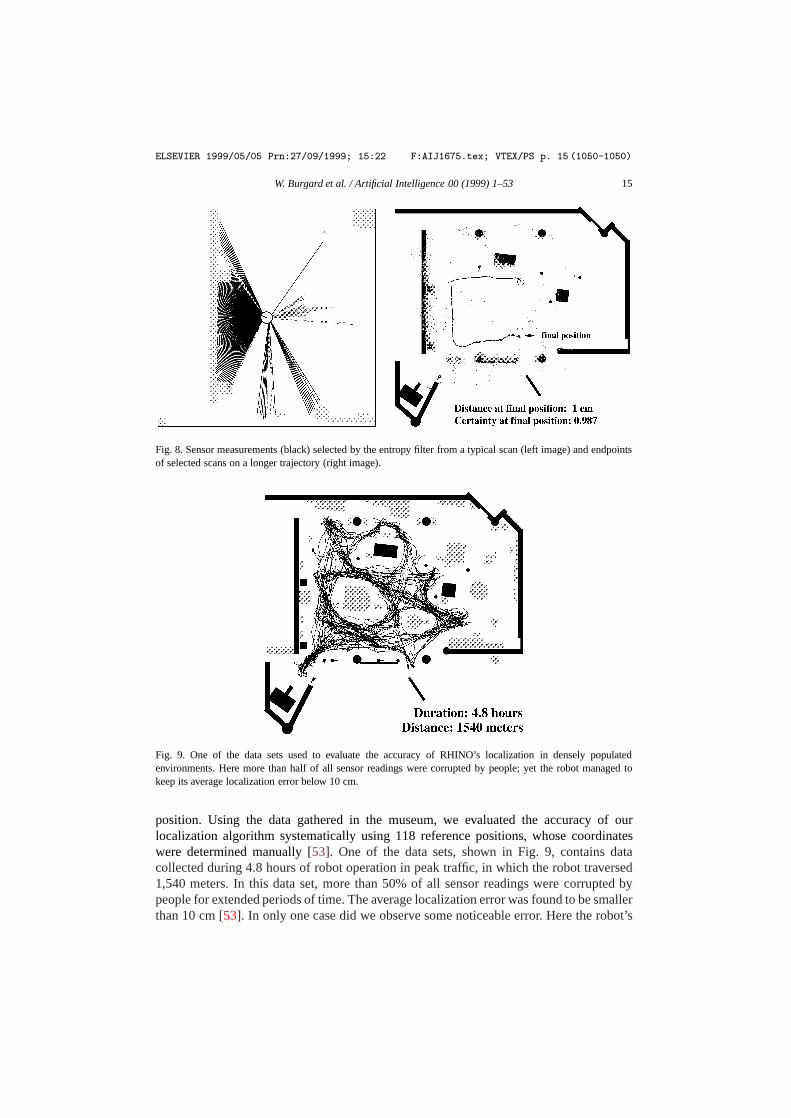
Fig. 8 shows a prototypical situation which illustrates the entropy gain filter. Shown thereare examples where RHINO has been projected into the map at its most likely position.The lines indicate the current proximity measurements, some of which correspond tostatic obstacles that are part of the map, whereas others are caused by humans (max-rangemeasurements are not shown). The different shading of the measurements demonstrates theresult of the entropy gain filter. The black values reduce entropy, whereas the gray valueswould increase the robot’s entropy and are therefore filtered out. Here all measurementsof humans are successfully filtered out. These examples are prototypical. In the museumexhibit, we never observed that a reading caused by a dynamic obstacle (such as a human)was not successfully filtered out. We did observe, however, that the robot occasionallyfiltered out measurements that stemmed from stationary obstacles that were part of the map.
The entropy gain filter proved to be highly effective in identifying non-static obstaclesand in filtering sensor readings accordingly. Throughout the complete deployment period,the robot incorporated sufficiently many sensor readings that it never lost track of its
ELSEVIER 1999/05/05 Prn:27/09/1999; 15:22 F:AIJ1675.tex; VTEX/PS p. 15 (1050-1050)
W. Burgard et al. / Artificial Intelligence 00 (1999) 1–53 15
Fig. 8. Sensor measurements (black) selected by the entropy filter from a typical scan (left image) and endpointsof selected scans on a longer trajectory (right image).
Fig. 9. One of the data sets used to evaluate the accuracy of RHINO’s localization in densely populatedenvironments. Here more than half of all sensor readings were corrupted by people; yet the robot managed tokeep its average localization error below 10 cm.
position. Using the data gathered in the museum, we evaluated the accuracy of ourlocalization algorithm systematically using 118 reference positions, whose coordinateswere determined manually [53]. One of the data sets, shown in Fig. 9, contains datacollected during 4.8 hours of robot operation in peak traffic, in which the robot traversed1,540 meters. In this data set, more than 50% of all sensor readings were corrupted bypeople for extended periods of time. The average localization error was found to be smallerthan 10 cm [53]. In only one case did we observe some noticeable error. Here the robot’s

ELSEVIER 1999/05/05 Prn:27/09/1999; 15:22 F:AIJ1675.tex; VTEX/PS p. 16 (1050-1134)
16 W. Burgard et al. / Artificial Intelligence 00 (1999) 1–53
internal belief deviated approximately 30 cm from the real position. As a result, the robottouched a large, invisible metal plate in the center of the museum. The localization errorwas preceded by a failure of the robot’s sonar sensors for an unknown duration of time.
Unfortunately, the basic entropy gain filter also has a disadvantage. When applied asdescribed above, it impairs the robot’s ability to recover from large errors in its localization.This is because if the robot’s position estimate is wrong, the entropy gain filter might filterout those sensor readings that convey information about its correct position, making arecovery impossible. To solve this problem we always incorporated a randomly chosen setof readings. A successor of the entropy gain filter, which is better suited to proximitysensors and outperforms the entropy gain filter, is described in [53]. As discussed inmore depth there, Markov localization combined with the entropy gain filter was able toaccurately estimate the position of the robot throughout the entire deployment period, andthe entropy filter played a crucial role in its success. Additional comparative experimentalresults, using the data obtained in the museum, can be found in [53].
3.1.7. Finding peopleAs an aside, it is interesting to notice that the entropy gain filter fulfills a secondary
purpose in RHINO’s software. Sensor measurementsoi with 1H(P |oi) > γ (with γ > 0)indicate the presence of an unexpected obstacle, such as people and other objects notcontained in the map. Thus, the inverse of the entropy gain filter is a filter that candetect people. This filter differs from many other approaches in the literature on peopledetection [72,76] in that it can find people who donot move, and it can do this evenwhile the robot itself is in motion. As will be described in more detail below, this filter,in combination with a criterion that measures the robot’s progress towards its goal, wasused to activate the robot’s horn. As a result, the robot blew its horn whenever humansblocked its path; an effect, that most visitors found highly entertaining.
3.2. Mapping
The problem of mapping is the problem of estimating the occupancy of all〈x,y〉locations in the environment [10,41,106,147] from sensor data. Mapping is essential ifthe environment changes over time, specifically if entire passages can be blocked. In themuseum, stools or people often blocked certain regions or passages for extended durationsof time. RHINO’s ability to acquire maps on-the-fly enabled it to dynamically plan detours,which prevented it from getting stuck in many cases.
The statistical estimation involved in building occupancy maps from sensor data issimilar to the probabilistic estimation of the robot’s location. Letcxy denote a randomvariable with events in{0,1} that corresponds to the occupancy of a location〈x,y〉 (inworld coordinates). Here 1 stands foroccupied, and 0 stands forfree. The problem ofmapping is to estimate
P({cxy}|o(1), . . . , o(t)), (11)
where the set of all occupancy values{cxy} denotes the map. Since the set of variables to beestimated—the map—is usually extremely high-dimensional (many of our maps contain106 or more grid cells), it is common practice to treat the occupancy estimation problem

ELSEVIER 1999/05/05 Prn:27/09/1999; 15:22 F:AIJ1675.tex; VTEX/PS p. 17 (1134-1224)
W. Burgard et al. / Artificial Intelligence 00 (1999) 1–53 17
Table 3Mapping—the basic algorithm
(1) Initialization:P(cxy )← 0.5
(2) For each observationo do:
P(cxy)← 1−(
1+ P(cxy |o)1− P(cxy |o)
P (cxy)
1−P(cxy ))−1
independently for each location〈x,y〉 [106,147]. This effectively transforms the high-dimensional occupancy estimation problem into a collection of one-dimensional estimationproblems{
P(cxy |o(1), . . . , o(t))}
(12)
which can be tackled efficiently.
3.2.1. Temporal integration of evidenceThe temporal integration of sensor evidence is analogous to Markov localization.
Just like Markov localization, our mapping approach relies on the following Markovassumption
P(o(t)|cxy, ξ (t), d\o(t)
)= P (o(t)|ξ(t), cxy) (13)
which renders sensor data conditionally independent given the true occupancy of the gridcell 〈x,y〉. Hereo(t) stands for the sensor reading taken at timet . To separate the problemof mapping from the localization problem, it is assumed that the robot’s locationξ(t) isknown;1 henceforth, the estimation ofξ(t) will be omitted in the mathematical derivation.In our implementation, the maximum likelihood estimation
ξ (t) = argmaxξ (t)
P(ξ(t)
)(14)
is used as the robot’s location.Armed with all necessary assumptions, we are now ready to derive an efficient algorithm
for statistical occupancy estimation from data. The probability that a location〈x,y〉 isoccupied given the data is given by
P(cxy |o(1), . . . , o(t)
)= P(o(t)|cxy, o(1), . . . , o(t−1))P (cxy |o(1), . . . , o(t−1))
P (o(t)|o(1), . . . , o(t−1))
= P(o(t)|cxy)P (cxy |o(1), . . . , o(t−1))
P (o(t)|o(1), . . . , o(t−1))
= P(cxy |o(t)) P (o(t))P (cxy |o(1), . . . , o(t−1))
P (cxy) P (o(t)|o(1), . . . , o(t−1)). (15)
This transformation is obtained via Bayes rule, followed by applying the Markovassumption and a second application of Bayes rule.
1 See [150] for an approach to concurrent localization and mapping that relaxes these assumption and estimatesboth the robot’s location and the location of the obstacles using a single, mathematical approach.
ELSEVIER 1999/05/05 Prn:27/09/1999; 15:22 F:AIJ1675.tex; VTEX/PS p. 18 (1224-1323)
18 W. Burgard et al. / Artificial Intelligence 00 (1999) 1–53
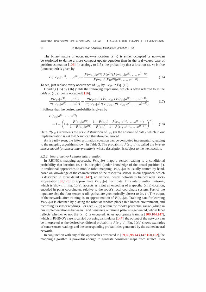
The binary nature of occupancy—a location〈x,y〉 is either occupied or not—canbe exploited to derive a more compact update equation than in the real-valued case ofposition estimation [106]. In analogy to (15), the probability that a location〈x,y〉 is free(unoccupied) is given by
P(¬cxy |o(1), . . . , o(t))= P(¬cxy |o(t)) P (o(t))P (¬cxy |o(1), . . . , o(t−1))
P (¬cxy) P (o(t)|o(1), . . . , o(t−1)). (16)
To see, just replace every occurrence ofcxy by¬cxy in Eq. (15).Dividing (15) by (16) yields the following expression, which is often referred to as the
oddsof 〈x,y〉 being occupied [116]:
P(cxy |o(1), . . . , o(t))P (¬cxy |o(1), . . . , o(t)) =
P(cxy |o(t)) P (¬cxy) P (cxy |o(1), . . . , o(t−1))
P (¬cxy |o(t)) P (cxy) P (¬cxy |o(1), . . . , o(t−1))(17)
it follows that the desired probability is given by
P(cxy |o(1), . . . , o(t))
= 1−(
1+ P(cxy |o(t))1− P(cxy |o(t))
1− P(cxy)P (cxy)
P (cxy |o(1), . . . , o(t−1))
1− P(cxy |o(1), . . . , o(t−1))
)−1
. (18)
HereP(cxy) represents theprior distribution of cxy (in the absence of data), which in outimplementation is set to 0.5 and can therefore be ignored.
As is easily seen, the latter estimation equation can be computed incrementally, leadingto the mapping algorithm shown in Table 3. The probabilityP(cxy |o) is called theinversesensor model(or sensor interpretation), whose description is subject to the next section.
3.2.2. Neural network sensor interpretationIn RHINO’s mapping approach,P(cxy |o) maps a sensor reading to a conditional
probability that location〈x,y〉 is occupied (under knowledge of the actual positionξ ).In traditional approaches to mobile robot mapping,P(cxy |o) is usually crafted by hand,based on knowledge of the characteristics of the respective sensor. In our approach, whichis described in more detail in [147], an artificial neural network is trained with Back-Propagation [65,123] to approximateP(cxy |o) from data. Thisinterpretation network,which is shown in Fig. 10(a), accepts as input an encoding of a specific〈x,y〉-location,encoded in polar coordinates, relative to the robot’s local coordinate system. Part of theinput are also the four sensor readings that are geometrically closest to〈x,y〉. The outputof the network, after training, is an approximation ofP(cxy |o). Training data for learningP(cxy |o) is obtained by placing the robot at random places in a known environment, andrecording its sensor readings. For each〈x,y〉 within the robot’s perceptual range (which inour implementation is between 3 and 5 meters), a training pattern is generated, whose labelreflects whether or not the〈x,y〉 is occupied. After appropriate training [100,104,147],which in RHINO’s case is carried out using a simulator [147], the output of the network canbe interpreted as the desired conditional probabilityP(cxy |o). Fig. 10(b) shows examplesof sonar sensor readings and the corresponding probabilities generated by the trained neuralnetwork.
In conjunction with any of the approaches presented in [59,60,98,143,147,150,152], themapping algorithm is powerful enough to generate consistent maps from scratch. Two

ELSEVIER 1999/05/05 Prn:27/09/1999; 15:22 F:AIJ1675.tex; VTEX/PS p. 19 (1323-1395)
W. Burgard et al. / Artificial Intelligence 00 (1999) 1–53 19
(a) (b)
Fig. 10. (a) An artificial neural network maps sensor measurements to probabilities of occupancy. (b) An examplesonar scan, along with the local map generated by the neural network. The darker a region, the more likely it isto be occupied.
(a) (b)
Fig. 11. Maps learned from scratch: (a) the Deutsches Museum Bonn, and (b) the Dinosaur Hall of Pittsburgh’sCarnegie Museum of Natural History, built in preparation of the installation of a similar tour-guide robot. Bothmaps were acquired in less than an hour.
example maps are shown in Fig. 11. Both maps were constructed in less than one hour.The scarceness of the map shown in Fig. 11(a), however, illustrates the large number ofundetectable obstacles (cf. the hand-crafted map shown in Fig. 18). Because of this, wechose to provide RHINO with a hand-crafted CAD map instead.

ELSEVIER 1999/05/05 Prn:27/09/1999; 15:22 F:AIJ1675.tex; VTEX/PS p. 20 (1395-1419)
20 W. Burgard et al. / Artificial Intelligence 00 (1999) 1–53
3.2.3. Integration of multiple mapsRHINO possesses two major proximity sensor systems, a ring of 24 ultrasonic
transducers (sonars) and a pair of laser range finders. Both sensor systems cover a full360 degree range. Since the perceptual characteristics of both systems are quite different,and since they are mounted at different heights, separate maps are built for each sensor.
From those, and from the hand-supplied CAD map, a single map is compiled using theconservative rule
P(cintxy)=max
{P(claser
xy ),P (csonarxy ),P (cCAD
xy )}, (19)
where the superscript “int” marks the integrated map and the various superscripts onthe right hand-side correspond to the respective maps. The integrated map is used fornavigation. The reader may notice that the integration rule (step (2) in Table 3) is inap-plicable if different sensors detect different obstacles, which is the case for the specificsensor systems considered in this article.
(a) (b) (c) (d)
Fig. 12. Integrating multiple maps: (a) CAD map, (b) laser map, (c) sonar map, and (d) the integrated map. Thescarceness of the sensor-based maps, when compared to the CAD map, indicates how few of the obstacles areactually detectable.
(a) (b)
Fig. 13. Two integrated maps, acquired in situations where a massive congestion of the museum forced the robotto take a detour.

ELSEVIER 1999/05/05 Prn:27/09/1999; 15:22 F:AIJ1675.tex; VTEX/PS p. 21 (1419-1496)
W. Burgard et al. / Artificial Intelligence 00 (1999) 1–53 21
Fig. 12 shows an example of the various maps and their integration. Other examples ofintegrated maps are shown in Fig. 13. These examples were recorded during peak traffichours. In both cases, a massive congestion made it impossible to make progress along theoriginal path. The robot’s ability to modify its map and hence its paths on-the-fly wasabsolutely essential for the high reliability with which the robot reached its destinations.
4. Planning and execution
RHINO motion control is implemented hierarchically, using three different modules forgenerating control. These are, in increasing levels of abstraction:
(1) Collision avoidance.This module directly sets the velocity and the motion directionof the robot so as to move in the direction of a target location while avoidingcollisions with obstacles. It is the only module that considers the dynamics of therobot.
(2) Motion planner.The motion planner consults the map to find shortest paths to anexhibit. The path is communicated to the collision avoidance module for execution.Since maps are updated continuously, the motion planner continuously revises itsplans.
(3) Task control module.The task control module coordinates the various robotactivities related to motion and interaction. For example, it determines the sequenceat which exhibits are visited during a tour, and it also determines the sequence ofsteps involved in the dialogue with the user.
The hierarchical organization is fairly classical [85]. Each module has its own way tomonitor the execution and reacts accordingly. In the museum, the robot was always inmotion—unless, of course, it intentionally stopped to explain an exhibit.
4.1. Collision avoidance
The task of the collision avoidance module is to determine the actual motion directionand velocity of the robot so as to operate the robot safely while maximizing its progresstowards its goal location. The majority of literature on mobile robot collision avoidancesuffers from two limitations, both of which are critical in environments like the museum.
(1) Inability to handle invisible obstacles.Virtually all existing methods for collisionavoidance are purely sensor-based, i.e., they only consult the robot’s sensors todetermine collision-free motion [13,50,71,78,79,137]. If all obstacles can be sensed,such strategies suffice. However, since some of the obstacles in the museum wereinvisible, a purely sensor-based approach would have been likely to fail.
(2) Inability to consider dynamics.With few exceptions [50,137], existing approachesmodel only the kinematics of the robot and ignore dynamic effects such as inertia.At lower speeds (such as 20 cm/sec), the dynamics of mobile robots can safelybe ignored. At higher speeds (such as 80 cm/sec), however, the robot’s inertia canprohibit certain maneuvers, such as sudden stops or sharp turns. Since one of therequirements in the museum was to operate at walking speed, it was essential thatthe robot’s dynamics were taken into account.

ELSEVIER 1999/05/05 Prn:27/09/1999; 15:22 F:AIJ1675.tex; VTEX/PS p. 22 (1496-1652)
22 W. Burgard et al. / Artificial Intelligence 00 (1999) 1–53
RHINO’s collision avoidance module, which is calledµDWA (short for: model-baseddynamic window algorithm), specifically addresses these limitations [52]. µDWA consultsa hand-supplied map of the environment to avoid collisions with obstacles that cannot besensed. The map is also used to bound the area in which the robot operates. To ensuresafe motion at high speed, constraints imposed by the robot’s dynamics are explicitlyconsidered.
4.1.1. The dynamic window algorithmThe key idea ofµDWA is to choose control directly in thevelocity spaceof the robot,
that is thetranslational and rotational velocity. As shown in [50], robots with fixedvelocity always travel on a circular trajectory whose diameter is determined by the ratioof translational and rotational velocity. Motor current (torque) change the velocity of therobot and, as a consequence, its motion direction. The problem of collision avoidance is,thus, the problem of selecting appropriate velocities for translation and rotation.
In regular time intervals (every .25 seconds),µDWA chooses velocities so as to bestobey various hard and soft constraints (see also [122]):
(1) Hard constraintsare vital for a robot’s safety and are imposed by torque limits.µDWA considers two types of hard constraints:torque constraintsand safetyconstraints. Torque constraints rule out velocities that physically cannot be attained(e.g., a fast moving robot cannot take a 90 degree turn). Safety constraints rule outvelocity settings that would inevitably lead to a collision with an obstacle. Noticethat hard constraints do not specify preferences among the different control options;neither do they take into account the robot’s goal.
(2) Soft constraintsexpresspreferencesfor both the motion direction and the velocityof the robot.µDWA measures the progress towards the goal by trading off threedifferent soft constraints, which measure(1) translational velocity,(2) heading towards the target position, and(3) forward clearance.If combined in the right ratio [50], these criteria lead to goal-directed behavior whilegraciously avoiding collisions.
Consider the situation depicted in Fig. 14, in which the robot is nearly in straight motionat a translational speed of about 40 cm/sec (the location of obstacles as perceived by therobot are shown in Fig. 15). Fig. 17 depicts the whole velocity space, in which each axiscorresponds to a velocity (translational and rotational). The robot’s current velocity is inthe center of the small rectangular box in the diagram, called thedynamic window. Thiswindow includes all velocities that can be attained in the next 0.25 seconds under therobot’s torque limits. Nearby obstacles carve out regions in the diagram (shown there inwhite), as those velocities would inevitably lead to a collision. The remaining velocitiesare then evaluated according to a superposition of the three soft constraints listed above,which favors velocity vectors with high translational velocity and for which the robot’sheading direction points towards the goal. The overall evaluation of each velocity pair isrepresented by its grey level, where darker values correspond to velocity pairs with highervalue. The cross marksµDWA’s final selection, which makes the robot follow the (circular)trajectory shown in Fig. 16.

ELSEVIER 1999/05/05 Prn:27/09/1999; 15:22 F:AIJ1675.tex; VTEX/PS p. 23 (1652-1661)
W. Burgard et al. / Artificial Intelligence 00 (1999) 1–53 23
Fig. 14. Scan of the laser sen-sors, missing much of the largecenter obstacle.
Fig. 15. Obstacle line field,purely sensor-based. Withoutmap information, the robotwould collide with an “invis-ible” obstacle.
Fig. 16. Obstacle line fieldenriched using virtual sen-sors. Here the collision isavoided. The circular trajec-tory visualizes the control,as chosen byµDWA for thenext 0.25 seconds.
Fig. 17. Each control is a combination of translational (y-axis) and rotational (x-axis) velocity. The darker acontrol, the higher its value. Also shown here is thedynamic windowof velocities that can actually be attained.The cross marks the control chosen byµDWA.
4.1.2. Integrating sensor readings and mapsµDWA integrates “real” proximity measurements, obtained from the robot’s various
sensors (tactile, infrared, sonar, laser), with “virtual” proximity measurements, generatedusing a map of the environment. Fig. 18 shows the map that was used in the museum forthis purpose. This map marks as dark grey all regions that contain obstacles that cannotbe sensed. This map was also used to limit the robot’s operational range. By addingappropriate virtual obstacles (shown in light grey) it can be ensured that the robot doesnot accidentally leave the area where it is supposed to operate.

ELSEVIER 1999/05/05 Prn:27/09/1999; 15:22 F:AIJ1675.tex; VTEX/PS p. 24 (1661-1696)
24 W. Burgard et al. / Artificial Intelligence 00 (1999) 1–53
Fig. 18. This map depicts, in dark grey, obstacleswhich could be detected, and in light grey, theboundary of the robot’s operational area.
Fig. 19. Probability of measuring a given distance underdifferent degrees of certainty.
Just like the real sensors (tactile, infrared, sonar, laser), the virtual sensors inµDWAare assumed to be mounted on a circular array around the robot. The generation of virtualmeasurements is not straightforward, as the robot never knows exactly where it is; instead,it is given the beliefP(ξ) that assigns conditional probabilities to the various locationsξ .At first glance, one might want to use the maximum likelihood position
ξ∗ = argmaxξP (ξ) (20)
to generate virtual proximity sensor measurements. However, such an approach would bebrittle, since it ignores the robot’s uncertainty.µDWA uses a more robust rule which takesuncertainty into account, by generating virtual measurements so that with high likelihood(e.g., 99%), virtual measurements underestimate the actual distance to the nearest object.To explain how this is done, let us first consider situations in which the robot positionξ is known. Recall thatdist(ξ) denotes the distance an ideal (noise-free) sensor wouldmeasure if the robot’s position wasξ , and letX denote a random variable that modelsthe measurement of this ideal sensor. Obviously, the probabilityP(X = o|ξ) is given by aDirac distribution:
P(X = o|ξ)={
1, if o= dist(ξ),
0, if o 6= dist(ξ).(21)
In our case, the robot only has a probabilistic beliefP(ξ) as to where it might be. Underthis belief, the probability that the sensor returns a valueo is given by
P(X = o)=∫P(X = o|ξ) P (ξ)dξ. (22)
The probability that the sensor measures a value larger thano is given by
P(X > o)=∫P(X > o|ξ) P (ξ)dξ =
∫∫o′>o
P(X = o′|ξ) P (ξ)do′ dξ

ELSEVIER 1999/05/05 Prn:27/09/1999; 15:22 F:AIJ1675.tex; VTEX/PS p. 25 (1696-1785)
W. Burgard et al. / Artificial Intelligence 00 (1999) 1–53 25
=∫o′>o
P(X = o′)do′. (23)
µDWA generates virtual measurements using a conservative rule: The measurement of avirtual sensor is the largest distance that, with 99% probability, underestimates the truedistance.
o∗ = sup{o: P(X > o)> .99
}. (24)
Let us illustrate this approach using two examples. Fig. 7 show two situations, one in whichthe robot is uncertain about its position, and one in which it is fairly certain. Both situationsinduce different densitiesP(X = o), which are shown in Fig. 19. The solid curve depictsP(X = o) in the uncertain case, whereas the dashed curve illustratesP(X = o) when therobot is certain. As is easy to be seen,P(X = o) is fairly unspecific in the uncertain case,whereas it is narrow in the certain case. The vertical lines (solid and dashed) indicate thevirtual reading thatµDWA generates in either situation. With 99% probability, the realdistance is larger than the distance suggested by the virtual reading. This conservative ruleensures that the robot does not collide with any of the invisible obstacles, unless it assignsless than 1% probability to its actual position.
Both virtual and real measurements form the basis for determining the robot’s motiondirection and velocity. Fig. 16 shows the integrated sensor information (real and virtual).Fig. 16 also shows the trajectory chosen byµDWA, which safely avoids collision withthe center obstacle. This figure demonstrates that a purely sensor-based approach isinappropriate.
The collision avoidance module proved to be highly effective in the museum. Because ofthe unified approach to setting speed and motion direction, the approach often maintainedwalking speed even in cluttered environments. The robot reacted quickly when peopleblocked its way, which prevented visitors from perceiving the robot as a potential threat.We never observed that parents kept their children—many of whom were much shorterthan the robot—from approaching the robot.
4.2. Motion planning
The collision avoidance module only considers local constraints. As any local motionplanning method, cannot cope with U-shaped obstacles and similar configurations thatrequire unbounded look-ahead. RHINO’s motion planning module takes a more globalview. Its task is to determine globally shortest paths to arbitrary target points. Pathsgenerated by the motion planner are then communicated to the collision avoidance routinefor execution.
The idea for path planning is to let the robot always move on a minimum-cost path tothe next exhibit. The cost for traversing a grid cell〈x,y〉 is proportional to its occupancyvalueP(cint
xy) (cf. Eq. (19)). The minimum-cost path is computed using a modified versionof value iteration, a popular dynamic programming algorithm [6,70]:

ELSEVIER 1999/05/05 Prn:27/09/1999; 15:22 F:AIJ1675.tex; VTEX/PS p. 26 (1785-1836)
26 W. Burgard et al. / Artificial Intelligence 00 (1999) 1–53
(1) Initialization. The grid cell that contains the target location is initialized with 0, allothers with∞:
Vx,y←{
0, if 〈x,y〉 target cell,
∞, otherwise.
(2) Update loop.For all non-target grid cells〈x,y〉 do:
Vx,y← min1x=−1,0,11y=−1,0,1
{Vx+1x,y+1y + P(cx+1x,y+1y)
}.
Value iteration updates the value of all grid cells by the value of their best neighbors,plus the costs of moving to this neighbor (just like A* [110]). Cost is here equivalentto the probabilityP(cx,y) that a grid cell〈x,y〉 is occupied. The update rule isiterated. When the update converges, each valueVx,y measures thecumulative costfor moving to the nearest goal. However, control can be generated at any time, longbefore value iteration converges.
(3) Determine motion direction.To determine where to move, the robot generates aminimum-cost path to the goal. This is done by steepest descent inV , starting at theactual robot position. The steepest descent path is then post-processed to maintain aminimum clearance to the walls. Determining the motion direction is done in regulartime intervals and is fully interleaved with updatingV .
Fig. 20 showsV after convergence for a typical situation in the museum, using the mapshown in Fig. 18. The grey-level indicates the cumulative costsV for moving towards thegoal point. Notice that every local minimum in the value function corresponds to a goal, ifmultiple goals exist. Thus, for every point〈x,y〉, steepest descent inV leads to the nearestgoal point.
Fig. 20. The motion planner uses dynamic programming to compute the shortest path to the nearest goal(s)for every location in the unoccupied space, as indicated by the gray shading. Once the distance has beencomputed, paths are generated by hill-climbing in distance space. An additional post-processing step increasesthe side-clearance to obstacles.

ELSEVIER 1999/05/05 Prn:27/09/1999; 15:22 F:AIJ1675.tex; VTEX/PS p. 27 (1836-1903)
W. Burgard et al. / Artificial Intelligence 00 (1999) 1–53 27
Unfortunately, plain value iteration is too inefficient to allow the robot to navigate whilesimultaneously learning maps. Strictly speaking, the basic value iteration algorithm canonly be applied if the cost function does not increase (which frequently happens when themap is modified). This is because when the cost function increases, previously adjustedvaluesV might become too small. While value iteration quickly decreases values that aretoo large,increasingtoo small a value can be arbitrarily slow [143,147]. Consequently, thebasic value iteration algorithm requires that the value function be initialized completely(step (1)) whenever the map—and thus the cost function—is updated. This is veryinefficient, since the map is updated almost constantly.
To avoid complete re-initializations, and to further increase the efficiency of theapproach, the basic paradigm was extended in the following way:
(4) Selective reset phase.Every time the map is updated, valuesVx,y that are too smallare identified and reset. This is achieved by the following loop, which is iterated:For all non-goal〈x,y〉 do:
Vx,y←∞ if Vx,y < min1x=−1,0,11y=−1,0,1
{Vx+1x,y+1y + P(cx+1x,y+1y)
}.
Notice that the remainingVx,y-values are not affected. Resetting the value tablebears close resemblance to value iteration.
(5) Bounding box.To focus value iteration, a rectangular bounding box[xmin, xmax]×[ymin, ymax] is maintained that contains all grid cells in whichVx,y may change.This box is easily determined in the value iteration update. As a result, value iterationfocuses on a small fraction of the grid only, hence converges much faster. Notice thatthe bounding box bears similarity to prioritized sweeping [105].
Value iteration is a very general procedure, which has several properties that make itattractive for real-time mobile robot navigation:• Any-time algorithm.Value iteration can be understood as an any-time planner [38],
since it allows the generation of a robot action at (almost) any time, long before valueiteration has converged. It allows the robot to move in real-time, even though some ofits motion commands might be sub-optimal.• Full exception handling.Value iteration pre-plans for arbitrary robot locations. This
is becauseV is computed for every location in the map, not just the currentlocation of the robot. Consequently, the robot can quickly react if it finds itselfin an unexpected location, and generate appropriate motion directions without anyadditional computational effort. This is particularly important in our approach, sincethe collision avoidance module adjusts the motion direction commanded by theplanner based on sensor readings and dynamic constraints.
In the museum, the motion planner was fast enough for real-time operation. In grid mapsof size 30× 30 meter and with a spatial resolution of 15 cm, optimized value iteration,done from scratch, requires approximately one to five seconds on a SUN Sparc station.In cases where the selective reset step does not reset large fractions of the map (whichis the common situation), value iteration converges in much less than a second. Fig. 13shows situations in which a passage is temporarily blocked, along with partially executedplans generated by the motion planner. Such situations occurred frequently in the museum,and without the ability to dynamically change the map and generate new plans, the robot

ELSEVIER 1999/05/05 Prn:27/09/1999; 15:22 F:AIJ1675.tex; VTEX/PS p. 28 (1903-2008)
28 W. Burgard et al. / Artificial Intelligence 00 (1999) 1–53
would have frequently been stuck for extended durations of time (e.g., waiting for a stoolto be moved away). The motion planner, together with the collision avoidance and thevarious state estimation modules described above, provided the robot with the ability tosafely move from one exhibit to another, while adjusting the velocity to the circumstances,circumventing obstacles when possible, but choosing completely different trajectorieswhen passages were blocked.
4.3. High-level task control
RHINO also employs a high-level planner, which is responsible for the composition ofentire tours.
The task control module coordinates the various robot activities related to motion anduser interaction at the highest level. It transforms abstract, user-level commands (such as:“give tour number three”) into a sequence of appropriate actions, where actions eithercorrespond to motion commands (e.g., “move to exhibit number five”) or control therobot’s user interface (e.g., “display image four” and “play pre-recorded message numberseventeen”). The task control module also monitors the execution and modifies task-levelplans if necessary.
In the museum exhibition, the primary role of the task control module was to determinethe order at which exhibits were visited, and to control the user interaction to ensure therobot functioned in accordance to the user’s demands. When tours were given to realvisitors, the job of the task control module was to monitor and control the dialogue withthe visitor, and to monitor plan execution. Internet users were able to compose tours byselecting individual tour items. Since multiple Internet users often sent commands at thesame time, there was a combinatorial problem of sequencing exhibits appropriately.
RHINO’s task control monitor is an augmented version of GOLOG, which has beendescribed in depth elsewhere [95]. GOLOG was chosen for two primary reasons: First,its seamless integration of programming and planning makes it a promising framework tospecify high-level control. However, GOLOG lacks several features necessary for robotcontrol in unpredictable and dynamic environments. The second reason for choosingGOLOG, thus, underlines a general interest to better understand how to integrate physicalrobot control with high level planning and decision tools, which have been subject ofintense AI research ever since its interception.
GOLOG is a first-order logical language that represents knowledge in the situationaction calculus [96]. It uses a built-in theorem prover to generate plans and to verify theircorrectness [103]. Programs (and plans) in GOLOG are sequences of elemental actionsexpressed in a logical language usingif-then-else rulesandrecursive procedures. GOLOGalso requires the programmer to provide an abstract model of the robot’s environment (adomain theory), describing the effects of its actions. The key benefit of GOLOG is thatit facilitates designing high-level controllers by seamlessly integrating programming andproblem solving [95,96]. Table 4 depicts an example GOLOG program for schedulingrequests by Internet users. It basically specifies that the robot shall serve all pendingrequests by moving to the corresponding position and explaining it, and return to its homingposition thereafter.

ELSEVIER 1999/05/05 Prn:27/09/1999; 15:22 F:AIJ1675.tex; VTEX/PS p. 29 (2008-2084)
W. Burgard et al. / Artificial Intelligence 00 (1999) 1–53 29
Table 4Fraction of the GOLOG program for the Internet tour-guide robot
proc internet-tourguidewhile (∃ exhibit) request(exhibit)∧ next(exhibit)do
(π exhibit).goto(exhibit); explain(exhibit)endWhilegoto(homing-position)endProc
proc goto(loc)if robotLocation(robotloc)∧ robotloc 6= loc then drive(loc)endIfendProc
Unfortunately, GOLOG, in its current form, suffers from several limitations such as thelack of sensing, interaction, and execution monitoring.2 Also, there is a mismatch betweenthe level of abstraction of GOLOG actions and those the robot is able to perform, thusmaking it difficult to directly control the low-level software from GOLOG:
Sensing and interaction: GOLOG is unable to accept and react to exogenous events. Itcannot handle plans conditioned on events not known in the beginning of programexecution. In the museum, the robot’s actions are, of course, conditioned on user inputand various other circumstances, and the ability to react to exogenous events is essential.
Execution monitoring: By default, GOLOG assumes that actions always succeed if theirpreconditions are met. It does not monitor the execution of its actions. In practice,however, actions can fail, and it is important that the robot reacts adequately. Forexample, the actionwait_for_user_request() often does not result in a userresponse, and timeout mechanisms have to be employed to avoid getting stuckindefinitely.
Level of abstraction: The primitive actions provided by RHINO’s low-level softwarecomponents are too fine-grained to be used directly in GOLOG. For example, the actiongoto(exhibit)involves a collection of low-level control directives, such as setting track-points for the cameras, setting target locations for the motion planner, turning the robottowards the exhibit after arrival, etc. While in principle, GOLOG can cope with anygranularity, dealing with low-level action sequencing at the most abstract level wouldmake GOLOG programs cumbersome and difficult to understand.
These difficulties are overcome by an intermediate software layer, called GOLEX [63].GOLEX is a runtime and execution monitoring system for GOLOG, which extendsGOLOG in three aspects:• GOLEX integrates sensing and user interaction capabilities into GOLOG. It enables
the programmer to formulate conditional programs. Action sequences can beconditioned upon exogenous events (such as the arrival of a tour item request) and
2 In recent work, which was not available when RHINO’s software was developed, extensions of GOLOG wereproposed which address these shortcomings [36,37,91].
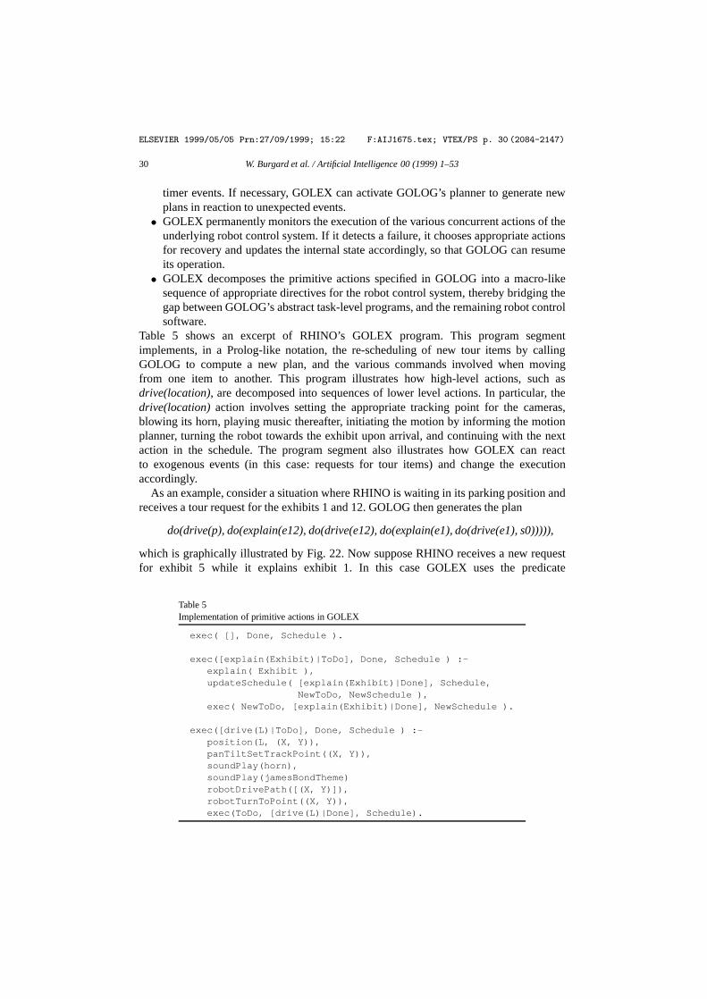
ELSEVIER 1999/05/05 Prn:27/09/1999; 15:22 F:AIJ1675.tex; VTEX/PS p. 30 (2084-2147)
30 W. Burgard et al. / Artificial Intelligence 00 (1999) 1–53
timer events. If necessary, GOLEX can activate GOLOG’s planner to generate newplans in reaction to unexpected events.• GOLEX permanently monitors the execution of the various concurrent actions of the
underlying robot control system. If it detects a failure, it chooses appropriate actionsfor recovery and updates the internal state accordingly, so that GOLOG can resumeits operation.• GOLEX decomposes the primitive actions specified in GOLOG into a macro-like
sequence of appropriate directives for the robot control system, thereby bridging thegap between GOLOG’s abstract task-level programs, and the remaining robot controlsoftware.
Table 5 shows an excerpt of RHINO’s GOLEX program. This program segmentimplements, in a Prolog-like notation, the re-scheduling of new tour items by callingGOLOG to compute a new plan, and the various commands involved when movingfrom one item to another. This program illustrates how high-level actions, such asdrive(location), are decomposed into sequences of lower level actions. In particular, thedrive(location)action involves setting the appropriate tracking point for the cameras,blowing its horn, playing music thereafter, initiating the motion by informing the motionplanner, turning the robot towards the exhibit upon arrival, and continuing with the nextaction in the schedule. The program segment also illustrates how GOLEX can reactto exogenous events (in this case: requests for tour items) and change the executionaccordingly.
As an example, consider a situation where RHINO is waiting in its parking position andreceives a tour request for the exhibits 1 and 12. GOLOG then generates the plan
do(drive(p), do(explain(e12), do(drive(e12), do(explain(e1), do(drive(e1), s0))))),
which is graphically illustrated by Fig. 22. Now suppose RHINO receives a new requestfor exhibit 5 while it explains exhibit 1. In this case GOLEX uses the predicate
Table 5Implementation of primitive actions in GOLEX
exec( [], Done, Schedule ).
exec([explain(Exhibit)|ToDo], Done, Schedule ) :-explain( Exhibit ),updateSchedule( [explain(Exhibit)|Done], Schedule,
NewToDo, NewSchedule ),exec( NewToDo, [explain(Exhibit)|Done], NewSchedule ).
exec([drive(L)|ToDo], Done, Schedule ) :-position(L, (X, Y)),panTiltSetTrackPoint((X, Y)),soundPlay(horn),soundPlay(jamesBondTheme)robotDrivePath([(X, Y)]),robotTurnToPoint((X, Y)),exec(ToDo, [drive(L)|Done], Schedule).

ELSEVIER 1999/05/05 Prn:27/09/1999; 15:22 F:AIJ1675.tex; VTEX/PS p. 31 (2147-2216)
W. Burgard et al. / Artificial Intelligence 00 (1999) 1–53 31
Fig. 21. Schedule of tour items for the exhibits 1and 12.
Fig. 22. Re-scheduled plan after receiving a requestfor a exhibit 5.
updateSchedule to initiate replanning using GOLOG’s planner. Since exhibit 5 iscloser than exhibit 12, the plan is revised to
do(drive(p), do(explain(e12), do(drive(e12), do(explain(e5), do(drive(e5), . . . ))))).
The resulting plan for the tour-guide is illustrated in Fig. 22. By providing these methodsfor executing primitive actions, reacting to user requests, and monitoring the progress ofthe robot, GOLEX provides the necessary “glue” between GOLOG and the rest of therobot control software.
5. Human-robot interaction
An important aspect of the tour-guide robot is its interactive component. User interfacesare of great importance for robots that are to interact with “normal” people. In settings suchas the museum, where people typically do not spend extensive amounts of time with therobot, two criteria are most important: ease of use, and interestingness. The user interfacesmust be intuitive, so that untrained and non-technical users can operate the system withoutinstruction. Interestingness is an important factor in capturing people’s attention.
RHINO possesses two user interfaces, one on-board interface to interact with peopledirectly, and one on the Web. The on-board interface is a mixed-media interface thatintegrates graphics, sound, and motion. The Web-based interface uses graphics and text.The interactive component was critical for RHINO’s user acceptance in the museum.Visitors of the museum paid considerably little attention to the fact that the robot navigatedsafely from exhibit to exhibit. Instead, many seemed to be most intrigued when the robotinteracted with them in some noticeable way. Some of RHINO’s most enthusiastic userswere less than six years old; others were over 80. The vast majority of users had not beenexposed to robots prior to visiting the museum. Since the majority of visitors stayed lessthan 15 minutes, it was critical that RHINO’s interface was easy-to-use and robust.

ELSEVIER 1999/05/05 Prn:27/09/1999; 15:22 F:AIJ1675.tex; VTEX/PS p. 32 (2216-2256)
32 W. Burgard et al. / Artificial Intelligence 00 (1999) 1–53
5.1. Mixed-media user interface
RHINO’s on-board control interface integrates graphics, motion, and spoken, pre-recorded language and sound.
(1) Initially, visitors can select a tour or, alternatively, listen to a brief, pre-recordedexplanation of the system (the “help text”). They indicate their choice by pressingone out of four colored buttons, shown in Fig. 23.
(2) When RHINO moves towards an exhibit, it displays an announcement on its screen.It also uses its camera-head to indicate the direction of its destination, by continuallypointing the camera towards the next exhibit. While in motion, the robot plays musicin order to entertain the people.
(3) At each exhibit, the robot first plays a brief pre-recorded verbal explanation. Usersare then given the choice to listen to more text or to move on to the next exhibit.Users are informed about their choice through the graphical display, and they canindicate their selection by pressing one of two lit buttons next to the screen. If nouser presses a button within five seconds, the robot defaults to the fast version of thetour where a minimum of verbal explanations are provided.
(4) When a tour is finished, the robot returns to a pre-defined starting position in theentrance area where it waits for new visitors.
Fig. 23 illustrates the interaction between visitors in the museum and the robot. The leftimages shows an example screen of the graphical display. All text was in German. The fourcolored buttons adjacent to the screen were the sole input interface.
Unfortunately, we were unable tosystematicallyevaluate the various components of theuser interface (see [129] for a detailed comparison based on a later tour-guide robot). Allevidence is therefore anecdotal. We observed that people consistently grasped the mainaspects of the interface within seconds, and without the need for further explanation. Theywere able to select a tour without being given any instructions. Often, they did not realizeimmediately that they were given the choice to obtain more detailed explanations, once
Fig. 23. On-board interface of the tour-guide robot. The users were required to press the buttons right from thedisplay to choose between different options (left image). During the tour the robot used its camera to point tothe exhibits. It showed text and graphics on its display and played pre-recorded sounds from CD to explain theexhibits (right image).
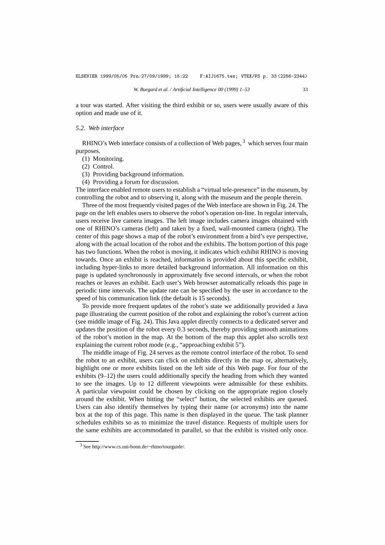
ELSEVIER 1999/05/05 Prn:27/09/1999; 15:22 F:AIJ1675.tex; VTEX/PS p. 33 (2256-2344)
W. Burgard et al. / Artificial Intelligence 00 (1999) 1–53 33
a tour was started. After visiting the third exhibit or so, users were usually aware of thisoption and made use of it.
5.2. Web interface
RHINO’s Web interface consists of a collection of Web pages,3 which serves four mainpurposes.
(1) Monitoring.(2) Control.(3) Providing background information.(4) Providing a forum for discussion.
The interface enabled remote users to establish a “virtual tele-presence” in the museum, bycontrolling the robot and to observing it, along with the museum and the people therein.
Three of the most frequently visited pages of the Web interface are shown in Fig. 24. Thepage on the left enables users to observe the robot’s operation on-line. In regular intervals,users receive live camera images. The left image includes camera images obtained withone of RHINO’s cameras (left) and taken by a fixed, wall-mounted camera (right). Thecenter of this page shows a map of the robot’s environment from a bird’s eye perspective,along with the actual location of the robot and the exhibits. The bottom portion of this pagehas two functions. When the robot is moving, it indicates which exhibit RHINO is movingtowards. Once an exhibit is reached, information is provided about this specific exhibit,including hyper-links to more detailed background information. All information on thispage is updated synchronously in approximately five second intervals, or when the robotreaches or leaves an exhibit. Each user’s Web browser automatically reloads this page inperiodic time intervals. The update rate can be specified by the user in accordance to thespeed of his communication link (the default is 15 seconds).
To provide more frequent updates of the robot’s state we additionally provided a Javapage illustrating the current position of the robot and explaining the robot’s current action(see middle image of Fig. 24). This Java applet directly connects to a dedicated server andupdates the position of the robot every 0.3 seconds, thereby providing smooth animationsof the robot’s motion in the map. At the bottom of the map this applet also scrolls textexplaining the current robot mode (e.g., “approaching exhibit 5”).
The middle image of Fig. 24 serves as the remote control interface of the robot. To sendthe robot to an exhibit, users can click on exhibits directly in the map or, alternatively,highlight one or more exhibits listed on the left side of this Web page. For four of theexhibits (9–12) the users could additionally specify the heading from which they wantedto see the images. Up to 12 different viewpoints were admissible for these exhibits.A particular viewpoint could be chosen by clicking on the appropriate region closelyaround the exhibit. When hitting the “select” button, the selected exhibits are queued.Users can also identify themselves by typing their name (or acronyms) into the namebox at the top of this page. This name is then displayed in the queue. The task plannerschedules exhibits so as to minimize the travel distance. Requests of multiple users forthe same exhibits are accommodated in parallel, so that the exhibit is visited only once.
3 See http://www.cs.uni-bonn.de/~rhino/tourguide/.
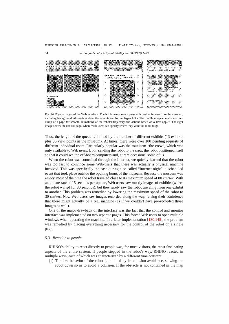
ELSEVIER 1999/05/05 Prn:27/09/1999; 15:22 F:AIJ1675.tex; VTEX/PS p. 34 (2344-2387)
34 W. Burgard et al. / Artificial Intelligence 00 (1999) 1–53
Fig. 24. Popular pages of the Web interface. The left image shows a page with on-line images from the museum,including background information about the exhibits and further hyper links. The middle image contains a screendump of a page for smooth animations of the robot’s trajectory and actions based on a Java applet. The rightimage shows the control page, where Web-users can specify where they want the robot to go.
Thus, the length of the queue is limited by the number of different exhibits (13 exhibitsplus 36 view points in the museum). At times, there were over 100 pending requests ofdifferent individual users. Particularly popular was the tour item “the crew”, which wasonly available to Web users. Upon sending the robot to the crew, the robot positioned itselfso that it could see the off-board computers and, at rare occasions, some of us.
When the robot was controlled through the Internet, we quickly learned that the robotwas too fast to convince some Web-users that there was actually a physical machineinvolved. This was specifically the case during a so-called “Internet night”, a scheduledevent that took place outside the opening hours of the museum. Because the museum wasempty, most of the time the robot traveled close to its maximum speed of 80 cm/sec. Withan update rate of 15 seconds per update, Web users saw mostly images of exhibits (wherethe robot waited for 30 seconds), but they rarely saw the robot traveling from one exhibitto another. This problem was remedied by lowering the maximum speed of the robot to30 cm/sec. Now Web users saw images recorded along the way, raising their confidencethat there might actually be a real machine (as if we couldn’t have pre-recorded thoseimages as well).
One of the major drawback of the interface was the fact that the control and monitorinterface was implemented on two separate pages. This forced Web users to open multiplewindows when operating the machine. In a later implementation [130,148], the problemwas remedied by placing everything necessary for the control of the robot on a singlepage.
5.3. Reaction to people
RHINO’s ability to react directly to people was, for most visitors, the most fascinatingaspects of the entire system. If people stepped in the robot’s way, RHINO reacted inmultiple ways, each of which was characterized by a different time constant:
(1) The first behavior of the robot is initiated by its collision avoidance, slowing therobot down so as to avoid a collision. If the obstacle is not contained in the map
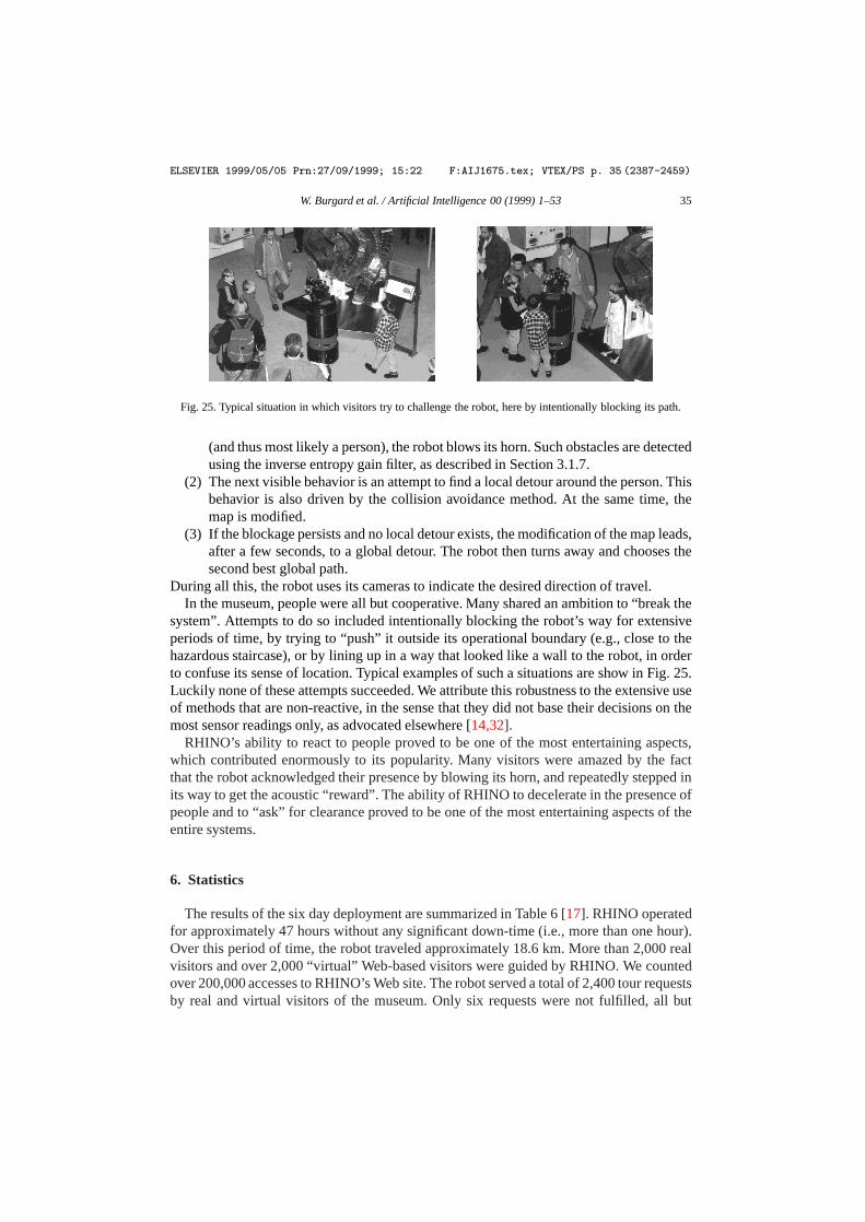
ELSEVIER 1999/05/05 Prn:27/09/1999; 15:22 F:AIJ1675.tex; VTEX/PS p. 35 (2387-2459)
W. Burgard et al. / Artificial Intelligence 00 (1999) 1–53 35
Fig. 25. Typical situation in which visitors try to challenge the robot, here by intentionally blocking its path.
(and thus most likely a person), the robot blows its horn. Such obstacles are detectedusing the inverse entropy gain filter, as described in Section 3.1.7.
(2) The next visible behavior is an attempt to find a local detour around the person. Thisbehavior is also driven by the collision avoidance method. At the same time, themap is modified.
(3) If the blockage persists and no local detour exists, the modification of the map leads,after a few seconds, to a global detour. The robot then turns away and chooses thesecond best global path.
During all this, the robot uses its cameras to indicate the desired direction of travel.In the museum, people were all but cooperative. Many shared an ambition to “break the
system”. Attempts to do so included intentionally blocking the robot’s way for extensiveperiods of time, by trying to “push” it outside its operational boundary (e.g., close to thehazardous staircase), or by lining up in a way that looked like a wall to the robot, in orderto confuse its sense of location. Typical examples of such a situations are show in Fig. 25.Luckily none of these attempts succeeded. We attribute this robustness to the extensive useof methods that are non-reactive, in the sense that they did not base their decisions on themost sensor readings only, as advocated elsewhere [14,32].
RHINO’s ability to react to people proved to be one of the most entertaining aspects,which contributed enormously to its popularity. Many visitors were amazed by the factthat the robot acknowledged their presence by blowing its horn, and repeatedly stepped inits way to get the acoustic “reward”. The ability of RHINO to decelerate in the presence ofpeople and to “ask” for clearance proved to be one of the most entertaining aspects of theentire systems.
6. Statistics
The results of the six day deployment are summarized in Table 6 [17]. RHINO operatedfor approximately 47 hours without any significant down-time (i.e., more than one hour).Over this period of time, the robot traveled approximately 18.6 km. More than 2,000 realvisitors and over 2,000 “virtual” Web-based visitors were guided by RHINO. We countedover 200,000 accesses to RHINO’s Web site. The robot served a total of 2,400 tour requestsby real and virtual visitors of the museum. Only six requests were not fulfilled, all but
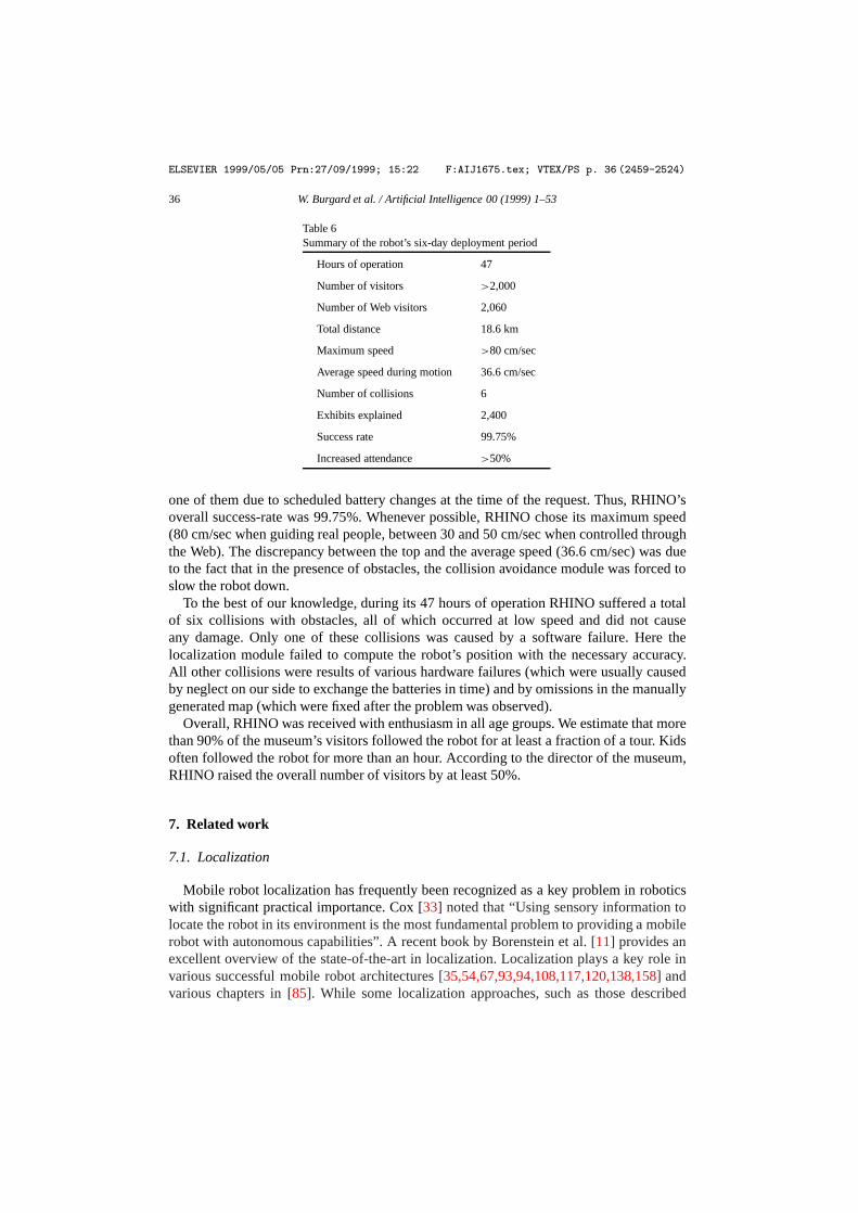
ELSEVIER 1999/05/05 Prn:27/09/1999; 15:22 F:AIJ1675.tex; VTEX/PS p. 36 (2459-2524)
36 W. Burgard et al. / Artificial Intelligence 00 (1999) 1–53
Table 6Summary of the robot’s six-day deployment period
Hours of operation 47
Number of visitors >2,000
Number of Web visitors 2,060
Total distance 18.6 km
Maximum speed >80 cm/sec
Average speed during motion 36.6 cm/sec
Number of collisions 6
Exhibits explained 2,400
Success rate 99.75%
Increased attendance >50%
one of them due to scheduled battery changes at the time of the request. Thus, RHINO’soverall success-rate was 99.75%. Whenever possible, RHINO chose its maximum speed(80 cm/sec when guiding real people, between 30 and 50 cm/sec when controlled throughthe Web). The discrepancy between the top and the average speed (36.6 cm/sec) was dueto the fact that in the presence of obstacles, the collision avoidance module was forced toslow the robot down.
To the best of our knowledge, during its 47 hours of operation RHINO suffered a totalof six collisions with obstacles, all of which occurred at low speed and did not causeany damage. Only one of these collisions was caused by a software failure. Here thelocalization module failed to compute the robot’s position with the necessary accuracy.All other collisions were results of various hardware failures (which were usually causedby neglect on our side to exchange the batteries in time) and by omissions in the manuallygenerated map (which were fixed after the problem was observed).
Overall, RHINO was received with enthusiasm in all age groups. We estimate that morethan 90% of the museum’s visitors followed the robot for at least a fraction of a tour. Kidsoften followed the robot for more than an hour. According to the director of the museum,RHINO raised the overall number of visitors by at least 50%.
7. Related work
7.1. Localization
Mobile robot localization has frequently been recognized as a key problem in roboticswith significant practical importance. Cox [33] noted that “Using sensory information tolocate the robot in its environment is the most fundamental problem to providing a mobilerobot with autonomous capabilities”. A recent book by Borenstein et al. [11] provides anexcellent overview of the state-of-the-art in localization. Localization plays a key role invarious successful mobile robot architectures [35,54,67,93,94,108,117,120,138,158] andvarious chapters in [85]. While some localization approaches, such as those described

ELSEVIER 1999/05/05 Prn:27/09/1999; 15:22 F:AIJ1675.tex; VTEX/PS p. 37 (2524-2597)
W. Burgard et al. / Artificial Intelligence 00 (1999) 1–53 37
in [69,88,139] localize the robot relative to some landmarks in a topological map, RHINO’sapproach localizes the robot in a metric space, just like those methods proposed in [7,145,150].
The vast majority of approaches is incapable of localizing a robot globally; instead,they are designed to track the robot’s position by compensating small odometric errors.Thus, they differ from the approach described here in that they require knowledge ofthe robot’s initial position; and they are not able to recover from global localizingfailures. Probably the most popular method for tracking a robot’s position is Kalmanfiltering [77,102], which represent uncertainty by single-modal distributions [60,61,98,125,140]. While these approaches are computationally extremely fast, they are unable tolocalize robots under global uncertainty—a problem which Engelson called the “kidnappedrobot problem” [44]. Recently, several researchers proposedMarkov localization, whichenables robots to localize themselves under global uncertainty [19,39,48,74,111,139].Global approaches have two important advantages over local ones: First, the initial locationof the robot does not have to be specified, and second, they provide an additional level ofrobustness, due to their ability to recover from localization failures. Unfortunately, noneof these methods were appropriate for the museum. This is because previous Markovlocalization methods relied on extremely coarse-grained,topological representations ofthe environment, making it impossible to navigate close to “invisible” obstacles. By usinga fine-grained, metric representation of space, our approach can localize a robot with muchhigher accuracy, and it can also deal with a wider variety of environments, including thosethat do not possess obvious geometric features such as corridors, intersections and doors.
In addition, the vast majority of approaches differ from the method described here inthat they can only cope withstaticenvironments, that is, environments that do not possessmeasurable state other than the robot’s location. These approaches are typically brittlein dynamic environments. The approach described in [80] uses cameras pointed towardsthe ceiling and thus cannot perceive most of the changes that occur in typical officeenvironments. Unfortunately, such an approach is only applicable if the ceiling containsenough structure for accurate position estimation. RHINO’s approach, by filtering outsensor data, has been demonstrated to function even in highly dynamic environments. Theresults obtained in the museum illustrate that it is capable of reliably localizing a roboteven if more than 50% of all sensor readings are corrupted by people (see also [53]).
Finally, most existing approaches are restricted in the type features that they consider.Many approaches reviewed in a recent survey book on this topic [11] are limited inthat they require modifications of the environment. Some require artificial landmarkssuch as bar-code reflectors [45], reflecting tape, ultrasonic beacons, or visual patternsthat are easy to recognize, such as black rectangles with white dots [10]. Of course,modifying the environment is not an option in many application domains. Some of themore advanced approaches use more natural landmarks that do not require modificationsof the environment. For example, the approaches of Kortenkamp and Weymouth [88] andMataric [101] use gateways, doors, walls, and other vertical objects to determine the robot’sposition. The Helpmate robot uses ceiling lights to position itself [80]. Dark/bright regionsand vertical edges are used in [31,159], and hallways, openings and doors are used bythe approach described in [82,135,138]. Others have proposed methods for learning whatfeature to extract, through a training phase in which the robot is told its location [58,114,

ELSEVIER 1999/05/05 Prn:27/09/1999; 15:22 F:AIJ1675.tex; VTEX/PS p. 38 (2597-2667)
38 W. Burgard et al. / Artificial Intelligence 00 (1999) 1–53
145,146]. These are just a few representative examples of many different features used forlocalization.
RHINO’s approach differs from all these approaches in that it does not extract predefinedfeatures from the sensor values. Instead, it directly processes raw sensor data. Such anapproach has two key advantages: First, it is more universally applicable since fewerassumptions are made on the nature of the environment; and second, it can utilize all sensorinformation, typically yielding more accurate results. Other approaches that process rawsensor data can be found in [60,61,98]; however, these approaches do not address the globallocalization problem.
7.2. Mapping
RHINO’s mapping approach is a variant of the well-known occupancy grid method.Occupancy grids have originally been proposed by Elfes and Moravec [41,42,106] andsince been adopted in numerous robotic systems (e.g., [13,16,62,127,160,161]). To date,occupancy grids have become the most successful metric approach to mobile robot mapacquisition. Our approach differs from previous ones in that neural networks are usedto learn the mapping from sensors to occupancy values; as a result, sensor readings areinterpreted in the context of their neighbors, which increases the accuracy of the resultingmaps [143,147].
Occupancy grids, however, are not the only approach to mobile robot mapping. Chatilaand Laumond [26] proposed to represent objects by polyhedra in a global coordinate frame.Cox [34] proposed to construct probabilistic trees to represent different, alternative modelsof the environment. In his work, Kalman filters and Bayesian methods are used for handlinguncertainty. Lu, Milios and Gutmann [59,98,99] presented an approach that memorizesraw proximity sensor data in a metric coordinate system, using an alignment procedurethat extracts lines from laser range finder data. Jeeves [144], an award-winning robot atthe 1996 AAAI mobile robot competition [87], constructs geometric maps incrementallyby concatenating wall segments detected in temporal sequences of sonar measurements.Jeeves’s design was strongly inspired by the work presented here; its inability to handledynamic environments and its strong commitment to parallel/orthogonal walls make itssoftware approach more brittle than the approach described here.
A statistical approach, which addresses both mobile robot localization and metricmapping, has been proposed in [150–152]. This approach uses efficient statisticalestimators to interleave localization and mapping. It is specifically tailored towardsbuilding maps of large, indoor environments, where the natural drift of the robot makesit difficult to maintain an accurate sense of a robot’s position. In the current application,this is not an issue, as an initial map of the environment is readily available.
All approaches discussed thus far fall into themetric paradigm [147]. There exists asecond, major paradigm to mapping, calledtopologicalmethods. This family of algorithmsrepresents environments by graphs, where nodes correspond to places and arcs correspondto actions for moving from one place to another. Often, topological graphs are enriched bylocal metric information to facilitate the navigation from one place to another. Among theearliest successful work in this field is an approach by Kuipers and Byun [89,90]. In theirapproach, topological places are defined as points that maximize the number of equidistant

ELSEVIER 1999/05/05 Prn:27/09/1999; 15:22 F:AIJ1675.tex; VTEX/PS p. 39 (2667-2734)
W. Burgard et al. / Artificial Intelligence 00 (1999) 1–53 39
obstacles (a similar idea can be found in Choset’s work, who refers to such points as“meetpoints” [27–29]). Topological places are connected by arcs, which contain metricinformation for locally moving from one place to another. The approach disambiguatesdifferent places by local sensor information (taken at a single node or, if necessary, at asmall number of neighboring nodes). In systematic simulations, this approach has beenfound to reliably learn large maps of indoor environments, even if sensor data is noisy.However, in these experiments the robot was equipped with a compass, which simplifiesthe localization problem significantly.
A different approach to learning topological maps was proposed by Mataric [101]. Heralgorithm acquires topological maps of the environment in which nodes correspond topre-defined landmarks such as straight wall segments. Neighboring topological entities areconnected by links. The topological representation is enriched by distance informationto help keeping track of the location of the robot. The approach was evaluated on aphysical robot and was found to be robust in practice. Its inability to maintain an exactposition estimate imposes intrinsic scaling limitations. Moreover, since the recognitionof landmarks in this approach involves robot motion, the approach might have severedifficulties in recognizing previously visited locations when approaching them fromdifferent directions (e.g., T-junctions).
Shatkay and Kaelbling proposed a method that learns topological map from landmarkobservations [133–135]. Their work extends work by Koenig and Simmons [82], whoinvestigated the problem of learning topological maps if a topological sketch of theenvironment is readily available. In Shatkay and Kaelbling’s work, no such assumptionis made. Their approach considers local topological information along with landmarklabel information (which is assumed to be observable), to disambiguate different locations.A key feature of their approach is the use of a recursive estimation routine (the Baum–Welsh algorithm [118]) that enables the topological mapper to refine position estimatesbackwards in time. As a result, their approach has built fairly large topological maps. Theirwork is similar to the metric approach in [150,152] in that it also employs the Baum-Welsh algorithm to interleave mapping and localization. Other topological approaches canbe found in [30,107,153,163].
7.3. Collision avoidance
In the field of collision avoidance for mobile robots, potential field methods [79] arehighly popular. They determine the steering direction of the robot by (hypothetically)assuming that obstacles assert negative forces on the robot and that the target locationasserts a positive force. By restricting the field of view to the close vicinity of therobot, these methods are computationally highly efficient. While the physical analogyof considering the robot as a free-flying object is attractive, Borenstein and Koren [84]identified that in practice, such methods often fail to find trajectories between narrowlyspaced obstacles; they also can produce oscillatory behavior in narrowly confinedcorridors. An extended version of the potential field approach is introduced in [78]. Bymodifying the potential function the motion of the robot becomes more efficient anddifferent behaviors such as wall following and tracking can be achieved.
ELSEVIER 1999/05/05 Prn:27/09/1999; 15:22 F:AIJ1675.tex; VTEX/PS p. 40 (2734-2799)
40 W. Burgard et al. / Artificial Intelligence 00 (1999) 1–53
The virtual force field histogramalgorithm [12], which closely resembles potentialfield methods, uses occupancy grids to represent information about obstacles close to therobot. This grid is generated and updated continuously using ultrasonic proximity sensors.Borenstein later extended this approach to thevector field histogram[13]. In this algorithm.occupancy information is transformed into a histogram description of the free space aroundthe robot, which is used to compute the motion direction and velocity for the robot.
All of the approaches discussed above generate motion commands for mobile robotsunder the assumption that infinite forces can be asserted on the robot—a commonassumption in the field of collision avoidance for indoor robots, as most robots are operatedat low speed where inertial effect can be neglected. However, to operate robots safelyat higher speeds (such as walking speed), it is necessary to take the robot dynamicsinto account. Both the dynamic window approach [16,49] and the “curvature velocitymethod” [137], which despite their similarity were developed independently, are designedto deal with the dynamics of mobile robots.
To deal with obstacles that cannot be detected by the robot’s sensors it is necessary tointegrate model-based information into reactive collision avoidance. Little attention hasbeen payed to this problem in the literature. In [126], an approach to motion planning isproposed which in principle could solve this problem. The emphasis of their work liesin the combination of global path planning and local collision avoidance. Here, motioncommands are generated based on a global model of the environment, which is updatedbased on sensory input. They propose a method which efficiently extracts a path to agoal point based on such a map. Unfortunately, the authors do not discuss the problemof robot dynamics and uncertain position estimation. Furthermore it is not clear how thestatic model of the environment is combined with the fast-changing information obtainedon-the-fly.
RHINO’s current method, calledµDWA [53], is specifically designed for environmentswhere not all obstacles can be perceived, guaranteeing safe navigation with highprobability even if the robot is not certain as to where it is. To the best of our knowledge,this feature is unique in the literature on mobile robot collision avoidance.
7.4. Motion planning
Robot motion planning has been subject to intense research, as documented by a largebody of literature on this topic (see, e.g., [92,131]). The majority of work addresses morecomplicated problems than the one addressed in this article, such as motion planning inhigher-dimensional and continuous space. Motion planning for circular mobile robots isoften performed in 2D, ignoring costs of rotation and the dynamics of the robot. Such amethodology yields only sub-optimal results, but greatly reduces the complexity of motionplanning, which is known to be exponential in the number of degrees of freedom [21,119].
A popular algorithm for robot motion planning is A* [110], which bears closeresemblance to the value iteration approach proposed here (see [81]). Both approachescan be used to find shortest paths to multiple goals, and they also generate values forarbitrary locations, facilitating rapid replanning in the face of unexpected events. The issueof efficient re-planning has also been addressed in [143] and by Stentz [141]. Stenz’s D*(dynamic A*) planning algorithm is designed to quickly repair motion plans if the map is

ELSEVIER 1999/05/05 Prn:27/09/1999; 15:22 F:AIJ1675.tex; VTEX/PS p. 41 (2799-2891)
W. Burgard et al. / Artificial Intelligence 00 (1999) 1–53 41
updated. RHINO’s motion planner does the same; given sufficient computation time, it isguaranteed to generate optimal plans with respect to the underlying representation.
In the AI community, conditional planning has also been a subject of intense research.A recent textbook [124] provides a collection of references to the most important workin this field. Almost all of the work surveyed here is focused on domains where themodel is specified by a collection of logical axioms, often expressed as STRIPS-likeoperators [110]. This work usually does not exploit the highly geometric nature of robotmotion planning, and is therefore not directly applicable. State-based representations,such as the one used here, are commonly used in the literature on partially observableMarkov decision processes (POMDPs) [73,75,97]. POMDPs are the mathematically themost appropriate framework to formulate the motion planning problem, since they canencompass uncertainty both in the map and the robot’s location. Unfortunately, thecomplexity of the domain does not permit efficient planning even if today’s best POMDPalgorithms are employed.
7.5. Task planning and control
Recent research has produced a variety of frameworks for task-level control (see, e.g.,[47,136] and various chapters in [85]). A recent AAAI symposium on this topic illustratesthe interest in this area [5]. To our knowledge, GOLOG is unique in its seamless integrationof a programming language and a powerful theorem prover for planning. Other special-purpose programming languages for mobile robots, such as COLBERT [83], do not featurebuilt-in problem solvers. COLBERT also stays below the level of abstraction of GOLOGin that it is designed to deal with raw sensor input and motor commands. However, sincethe expressive power of the situation calculus exceeds that of STRIPS-like planners (whichrely on an implicit close-world assumption), GOLOG is less efficient than most existingplanning algorithms (see [124]).
Historically, Nilsson’s SHAKEY robot was the first, successful demonstration of thesynthesis of symbolic, AI-type problem solving and low-level control. While SHAKEYwas a milestone in the history of mobile robotics, it suffered from a lack of robustnesson the low-level side, making it too brittle to operate in domains as dynamic as the oneconsidered in this paper. More recently, Haigh integrated PRODIGY [22] with a suiteof low-level software developed for CMU’s XAVIER project [138]. Her system, calledROUGE [64], uses PRODIGY to generate cost-optimal motion plans for XAVIER, a robotnavigating in the corridors of an office building. This approach differs from ours in that itdoes not offer a programming option on the task control level, i.e., all plans are generatedby the planner, not by the programmer.
7.6. Human robot interfaces
Most existing robots do not possess user-friendly interfaces. This is because mobilerobotics research tends to focus on issues related to navigation, not on human robotinteraction. Nevertheless, the need for more effective human robot interfaces has clearlybeen recognized. For example, in his M.Sc. Thesis, Torrance developed a natural languageinterface for teaching mobile robots names of places in an indoor environment [153].

ELSEVIER 1999/05/05 Prn:27/09/1999; 15:22 F:AIJ1675.tex; VTEX/PS p. 42 (2891-2938)
42 W. Burgard et al. / Artificial Intelligence 00 (1999) 1–53
Due to the lack of a speech recognition system, his interface still required the user tooperate a keyboard; however, the natural language component made instructing the robotsignificantly easier. More recently, Asoh and colleagues [4] developed an interface thatintegrates a speech recognition system into a phrase-based natural language interface.They successfully instructed their “office-conversant” robot to navigate to office doors andother significant places in their environment, using verbal commands. Other researchershave proposed vision-based interfaces that allow people to instruct mobile robots via armgestures. For example, Kortenkamp and colleagues [86] recently developed a gesture-based interface, which is capable of recognizing arm poses such as pointing towardsa location on the ground. In a similar effort, Kahn and colleagues [76] developed agesture-based interface which has been demonstrated to reliably recognize static arm poses(pose gestures) such as pointing. This interface was successfully integrated into Firby’sreactive plan-execution system RAP [47], where it enabled people to instruct a robot topick up free-standing objects. A recent paper by Waldherr and colleagues [157] extendsthese approaches todynamicgestures, i.e., gestures which are defined through motion,not just poses. Motion gestures, which are commonly used for communication amongpeople, provide additional freedom in the design of gestures. In addition, they reducethe chances of accidentally classifying arm poses as gestures that were not intended assuch.
Unfortunately, while these interfaces are important steps in the right direction, theyare not quite suited for application domains as museums, where people typically interactwith a robot for an extremely short duration. Most visitors spent less than 15 minutesfollowing the robot through the museum, and even RHINO’s most enthusiastic supportersstayed rarely for more than two hours. Under such circumstances, it is important that therobot appeals to the “intuitions” of its users. It is generally undesirable that users have tolearn how to interact with a robot, even if the nature of the interface (language, gestures)facilitates this process. We believe that we currently lack a convincing methodology for“intuitive” human robot interaction.
7.7. Integrations and applications
Various researchers have devised integrated systems similar to the one describedhere [85,128]. A good survey of fielded systems is provided in a recent book by Schraft andSchmierer [128]. For example, Siemens Corp. (Germany) has recently developed a mobilecleaning robot, which it successfully deployed in a supermarket [43]. Unfortunately, muchof their technology is proprietary. The robot differs from RHINO in that does not interactwith people; it also moves at much lower speed. We suspect that the basic softwarearchitecture is similar to the one used by RHINO. A second, prominent example of asuccessfully deployed robot is Helpmate Inc.’s Helpmate robot [80]. This robot has beendeployed at dozens of hospitals worldwide, where it carries food and other items throughhospital corridors. The Helpmate does not interact with people either, but it features aneasy-to-use interface which enables nurses to tell the robot where to go.
To the best of our knowledge, the concept of a tour-guide robot was first proposedby Horswill [68,69], who built a robot that guided visitors through the AI Lab at MIT.This robot, designed to demonstrate Horswill’s fast vision routines, did not require
ELSEVIER 1999/05/05 Prn:27/09/1999; 15:22 F:AIJ1675.tex; VTEX/PS p. 43 (2938-3000)
W. Burgard et al. / Artificial Intelligence 00 (1999) 1–53 43
modifications of the environment, just like RHINO (apart from colored tape at the boundaryof the robot’s operational range). However, it lacked the ability to modify its map; neithercould it avoid collisions with invisible obstacles or recover from global localizationfailures. RHINO’s approach relies to a much larger degree on internal state (location, map),which accounts for its enhanced level of robustness and capability required in environmentssuch as the one considered here.
Motivated by RHINO, Nourbaksh and colleagues recently installed a similar tour-guiderobot in the Carnegie Museum of Natural History in Pittsburgh, PA [112]. This robot,called CHIPS, has been operated successfully over a period of several months. CHIPSdiffers from RHINO in several aspect. To aid the navigation, CHIPS’s environment ismarked by bright orange-green markers, whose location is known. The robot does notpossess a planner; instead, it closely follows a pre-given path. When the robot’s sensorsare blocked, it typically waits for the blockage to disappear. CHIPS uses high-end multi-media technology to provide detailed explanations of exhibits, lasting in the order of 3minutes per exhibits. RHINO, in comparison, provides much shorter explanations. Finally,CHIPS lacks a Web interface.
Similarly motivated by RHINO’s success, we recently installed a more advanced tour-guide (called MINERVA) in the Smithsonian’s National Museum of American History inWashington, DC [148]. This robot was similar to RHINO, in that it shared many of thebasic navigation modules. However, it features an additional module for learning ceilingmaps and using those for localization, and it also possessed a drastically revised userinterface, aimed at providing the robot with a “life-like” character. Further details can befound in [148].
7.8. Robots on the Web
In recent years, several research teams have connected robots to the Web, enablingpeople all over the world to command robots remotely. One of the most prominentexamples is CMU’s XAVIER robot [138], which predates the work reported here. XAVIERis equipped with an interface similar to the one described here. Web-users can schedulerequests for moving to pre-specified locations where the robot tells a user-selected “joke”,and they can watch camera images recorded in regular time intervals. RHINO’s interfaceoffers a choice between JPEG images and Java applets; the latter option enables Web usersto run a robot simulator on their own machine, in which the robot’s location is animatedcontinuously. Users command both robots at an abstract level, and the low-level navigationsoftware ensures the robot’s safety.
Others have designed interfaces for the control of robot arms. The MERCURYsystem [56], which started its operation in 1994, was one of the first tele-operatedmanipulators on the Web. It enabled Web users to excavate artifacts buried in a sand-filledterrarium. This system required users to assume exclusive control over the manipulator.The TELE-GARDEN, successor of MERCURY, enabled people to plant flowers [57].Just like RHINO, this system was able to coordinate requests by multiple users. The“Mechanical Gaze Project” [115] enables visitors of a museum to examine exhibits fromvarious viewpoints, and with different distances. Other Web-connected robots include atele-operated “Eyebot”, a robot that carries a camera whose pictures are posted on the Web
ELSEVIER 1999/05/05 Prn:27/09/1999; 15:22 F:AIJ1675.tex; VTEX/PS p. 44 (3000-3064)
44 W. Burgard et al. / Artificial Intelligence 00 (1999) 1–53
(http://www.dma.nl/eyebot ), and “KhepOnTheWeb”, a table-top robot that Webusers can manually move through a maze (http://KhepOnTheWeb.epfl.ch ).
8. Summary
This article described the software architecture of a fully autonomous mobile robotdesigned to interact with people. The robot has been proven to function reliably inunmodified and densely populated environments, and it has equally been proven to interactsuccessfully with people. To reach this level of reliability, our approach extends a collectionof well-known algorithms for mobile robot state estimation, control, and user interaction,and integrates them into a single system. While most of the work reported here is well-grounded in previously approaches to mobile robotics, some critical innovations werenecessary to provide the robot with the necessary level of robustness.
RHINO’s localization method is based on Markov localization, a popular probabilisticlocalization method. Our approach extends the Markov localization paradigm by a methodfor filtering out noisy sensor data, which makes it extremely robust in highly dynamicenvironments. It also estimates the location of a robot at much higher resolution; anecessary requirement for navigating close to obstacles that cannot be sensed. The robotinherits its mapping algorithm from the decade-old literature on occupancy grid maps.It employs artificial neural networks for sensor interpretation, which allow it to interpretsensor readings in the context of its neighbors. As argued elsewhere [147], such anapproach improves the robustness of the mapping algorithm to noise (such as spectralreflection). RHINO also integrates maps from different sensor modalities.
RHINO employs a hybrid collision avoidance method (µDWA), specifically designedto operate in environments where not all obstacles can be sensed reliably. In addition tothe sensor readings, this approach assembles “virtual” sensor readings using a map of theenvironment. A key feature is its ability to generate safe motion even if the robot does notquite know where it is. This contrasts with previous methods, which are typically purelysensor-based and would thus fail in an environment as the museum. RHINO’s motionplanner is a version of dynamic programming, which, by spreading activation through free-space, effectively pre-plans for all possible exceptions. To accommodate the continuouschange of the map, the path planner contains a method for identifying where and whenreplanning becomes necessary. Task-level control is performed by GOLOG, an integratedprogramming language and theorem prover embedded in the situation action calculus.While this approach provides a powerful framework for designing high-level controllers,it alone is inappropriate to deal with various contingencies arising in robot control. Wetherefore designed GOLEX, an interface which provides the glue between GOLOG andthe rest of the software. GOLEX provides macros, conditional plans and an executionmonitor.
RHINO exhibits a degree of interactiveness typically not found on other mobile robots.It reacts to the presence of people in various ways—an aspect that we found to beessential to spark people’s enthusiasm. Both its command interface and its interfaceto the Web was specifically designed to appeal to novices. All these components areintegrated through a modular software architecture, designed to accommodate the various

ELSEVIER 1999/05/05 Prn:27/09/1999; 15:22 F:AIJ1675.tex; VTEX/PS p. 45 (3064-3132)
W. Burgard et al. / Artificial Intelligence 00 (1999) 1–53 45
bottlenecks in distributed computer networks. All computation is carried out completelyasynchronously, and the different modules communicate by sending messages to eachother. Computationally-intense modules were capable of adapting their requirements to theavailable resources, which is critical in a communication network that was often subject tolengthy communication delays.
During its six-day installation period, the robot performed reliably and excited thevisitors. The robot guided thousands of users to exhibits with almost perfect reliability,traversing more than 18.6 km at an average speed of 35 cm/sec. We did not modifythe museum in any way that would facilitate the robot’s operation; in fact, RHINO’ssoftware successfully coped with various “invisible” obstacles and the large number ofpeople. We believe that RHINO’s reliability and effectiveness in complex environmentsis unprecedented. The robot also raised the museum’s attendance by more than 50%,suggesting that robotic applications in the field of entertainment and education might becommercially viable.
9. Discussion
One of the key limitations of the current approach is its reliance on an accurate map ofthe environment. In the Deutsches Museum Bonn, it took us about a week to manuallyacquire the map, partially because of the non-orthogonal arrangement of exhibits andwalls. To remedy this problem, we recently devised a family of more powerful mappingtechniques [150,152]. These techniques make it possible to acquire maps of large-scale,cyclic environments from raw sensor data, collected while joy-sticking the robot throughits environments (see also Section 7.2, Fig. 11, and [148]). Augmenting such maps with“invisible” obstacles is straightforward, as the robot’s localization methods can be used toaccurately determine its position. These new techniques overcome an important limitationof the approach described here, effectively reducing the installation time for a robot bymore than an order of magnitude.
Another limitation arises from the fact that the pure entropy gain filter, used to filter outall corrupted sensor readings, impairs the robot’s ability to recover from global localizationfailure. As noted above, once the robot has lost track of its position entirely the entropygain filter may filter outall authentic sensor readings, making it impossible for the robot tore-localize itself. Recently, we proposednovelty filters[53], an extension of entropy gainfilters that takes into account the nature of the surprise in a sensor reading. In a systematicstudy using the data collected in the museum we found that novelty filters do not suffer thislimitation, while still retaining the full advantage of the entropy gain filter. We envision thatthis new filter will lead to more robust behavior in highly dynamic environments.
Finally, the interactive component of the robot can certainly be considered a firststep only. As reported above, user interaction was essential for the overall validity ofthe concept. RHINO’s interaction is quite limited, when compared to ongoing researchon human computer interaction and believable characters. While this paper was underreview, we developed a second generation tour-guide robot, called MINERVA [148], whichexhibited a much richer repertoire of interactive means. MINERVA was equipped with aface, used a finite state machine to emulate “moods”, and employed reinforcement learning

ELSEVIER 1999/05/05 Prn:27/09/1999; 15:22 F:AIJ1675.tex; VTEX/PS p. 46 (3132-3257)
46 W. Burgard et al. / Artificial Intelligence 00 (1999) 1–53
[75,142] to learn how to best attract people. In addition, MINERVA possessed a moreeffective Web interface, which gave users the freedom to send the robot to arbitrary pointsin the environment. Results of this more advanced interface are described in [129,130].Nevertheless, we believe that the issue of people interaction with service robots in publicplaces remains an open and promising research issue—which we have barely touched.
RHINO is just one out of a series of recent successful mobile robots [128]. Recentresearch in the field of mobile robotics has led to significant progress along variousdimensions. Applications such as robots that guide blind or mentally handicapped people,robots that clean large office buildings and department stores, robots that assist peoplein recreational activities, etc., are clearly in reach, and for many of those target domainsprototypes are readily available [128]. This recent, ongoing revolution has been triggeredby advances along various dimensions. Robotic hardware has steadily become cheaperand more reliable. Robotic software has matured, reaching critical levels of reliability,robustness, and flexibility.
We believe that the museum tour-guide is a prototypical example of a new generation ofmobile service robots. Many of the challenges in the museum tour-guide domain apply to awide variety of mobile robot applications: the necessity to navigate through highly dynamicand unstructured environments; the necessity to interact with people; and the necessityto operate in environments that cannot be modified. It is quite likely that robots similarto the one described here will soon be deployed in shopping malls, amusement centers,technology fairs, etc., where they will be receptionists, information kiosks, waiters, guides,but most of all: magnets that attract people. Similar robots may soon perform janitorialservices, operate at sites too dangerous for humans, or assist people in various aspects oftheir lives.
Through developing RHINO’s software and watching it operate in the DeutschesMuseum, we learned more than we can possibly describe in a single article. Among themost important lessons is the recognition that mobile robot navigation has progressedto a level at which robots can now navigate reliably even in densely populated spaces.In most aspects, such robots can now be installed in new sites within days, withouthaving to modify the environment (see also [150]). We also learned that human robotinterfaces are key prerequisites if robots are to become part of people’s everyday lives.We found that adaptive mechanisms are essential for operating robots in highly dynamicand unpredictable environments, as without the capability to revise its maps and itsplans, the robot would often have been stuck. Finally, we learned that entertainment isa highly promising application domain for mobile robotics. In most envisioned servicerobot applications, robots have to compete with human labor, whereas in the entertainmentsector, robots may generate revenue by simply exploiting the fact that they differ.
Acknowledgement
The authors thank Peter Frieß and his staff from the Deutsches Museum Bonn for theirenthusiastic support of this project.
This research is sponsored in part by DARPA via AFMSC (contract number F04701-97-C-0022), TACOM (contract number DAAE07-98-C-L032), and Rome Labs (contract

ELSEVIER 1999/05/05 Prn:27/09/1999; 15:22 F:AIJ1675.tex; VTEX/PS p. 47 (3257-3411)
W. Burgard et al. / Artificial Intelligence 00 (1999) 1–53 47
number F30602-98-2-0137), and also by the EC (contract number ERBFMRX-CT96-0049) under the TMR programme. The views and conclusions contained in this documentare those of the author and should not be interpreted as necessarily representing officialpolicies or endorsements, either expressed or implied, of DARPA, AFMSC, TACOM,Rome Labs, the United States Government, or the EC.
References
[1] R. Arkin, Behavior-Based Robotics, MIT Press, Boston, MA, 1989.[2] I. Asimov, Runaround, Faucett Crest, New York, 1942.[3] I. Asimov, I, Robot, Doubleday, 1950.[4] H. Asoh, S. Hayamizu, H. Isao, Y. Motomura, S. Akaho, T. Matsui, Socially embedded learning of office-
conversant robot jijo-2, in: Proc. IJCAI-97, Nagoya, Japan, 1997.[5] C. Baral, G. De Giacomo, K. Konolige, G. Lakemayer, R. Reiter, M. Shanahan (Eds.), AAAI Fall
Symposium, Workshop on Cognitive Robotics, Orlando, FL, AAAI Press, 1998.[6] R.E. Bellman, Dynamic Programming, Princeton University Press, Princeton, NJ, 1957.[7] M. Betke, L. Gurvits, Mobile robot localization using landmarks, Technical Report SCR-94-TR-474,
Siemens Corporate Research, Princeton, 1993. Will also appear in: IEEE Transactions on Robotics andAutomation.
[8] C.M. Bishop, Neural Networks for Pattern Recognition, Oxford University Press, Oxford, UK, 1994.[9] A. Blum, T.M. Mitchell, Combining labeled and unlabeled data with co-training, in: Proc. Conference on
Learning Theory (COLT), Madison, WI, 1998.[10] J. Borenstein, The nursing robot system, Ph.D. Thesis, Technion, Haifa, Israel, 1987.[11] J. Borenstein, B. Everett, L. Feng, Navigating Mobile Robots: Systems and Techniques, A. K. Peters,
Wellesley, MA, 1996.[12] J. Borenstein, Y. Koren, Real-time obstacle avoidance for fast mobile robots in cluttered environments, in:
Proc. of the IEEE International Conference on Robotics and Automation, 1990, pp. 572–577.[13] J. Borenstein, Y. Koren, The vector field histogram—Fast obstacle avoidance for mobile robots, IEEE
J. Robotics and Automation 7 (3) (1991) 278–288.[14] R.A. Brooks, A robust layered control system for a mobile robot, Technical Report AI memo 864,
Massachusetts Institute of Technology, Cambridge, MA, 1985.[15] R.A. Brooks, Intelligence without reason, in: Proc. IJCAI-91, Sydney, Australia, 1991, pp. 569–595.[16] J. Buhmann, W. Burgard, A.B. Cremers, D. Fox, T. Hofmann, F. Schneider, J. Strikos, S. Thrun, The mobile
robot Rhino, AI Magazine 16 (1) (1995).[17] W. Burgard, A.B., Cremers, D. Fox, D. Hähnel, G. Lakemeyer, D. Schulz, W. Steiner, S. Thrun, The
interactive museum tour-guide robot, in: Proc. AAAI-98, Madison, WI, 1998.[18] W. Burgard, A. Derr, D. Fox, A.B. Cremers, Integrating global position estimation and position tracking for
mobile robots: The dynamic Markov localization approach, in: Proc. IEEE/RSJ International Conferenceon Intelligent Robots and Systems (IROS-98), 1998.
[19] W. Burgard, D. Fox, D. Hennig, T. Schmidt, Estimating the absolute position of a mobile robot usingposition probability grids, in: Proc. AAAI-96, Portland, OR, AAAI Press/MIT Press, Menlo Park, CA,1996.
[20] W. Burgard, D. Fox, S. Thrun, Active mobile robot localization, in: Proc. IJCAI-97, Nagoya, Japan, MorganKaufmann, San Mateo, CA, 1997.
[21] J. Canny, The Complexity of Robot Motion Planning, MIT Press, Cambridge, MA, 1987.[22] J.G. Carbonell, C.A. Knoblock, S. Minton, Prodigy: An integrated architecture for planning and learning,
in: K. Van Lehn (Ed.), Architectures for Intelligence, Erlbaum, 1990.[23] G.C. Casella, R.L. Berger, Statistical Inference, Wadsworth & Brooks, Pacific Grove, CA, 1990.[24] V. Castelli, T. Cover, On the exponential value of labeled samples, Pattern Recognition Letters 16 (1995)
105–111.[25] V. Castelli, T. Cover, The relative value of labeled and unlabeled samples in pattern recognition with an
unknown mixing parameter, IEEE Trans. Inform. Theor. 42 (6) (1996) 2101–2117.

ELSEVIER 1999/05/05 Prn:27/09/1999; 15:22 F:AIJ1675.tex; VTEX/PS p. 48 (3411-3568)
48 W. Burgard et al. / Artificial Intelligence 00 (1999) 1–53
[26] R. Chatila, J.-P. Laumond, Position referencing and consistent world modeling for mobile robots, in: Proc.1985 IEEE International Conference on Robotics and Automation, 1985.
[27] H. Choset, Sensor based motion planning: The hierarchical generalized Voronoi graph, Ph.D. Thesis,California Institute of Technology, 1996.
[28] H. Choset, I. Konuksven, J.W. Burdick, Sensor based planning for a planar rod robot, in: Proc.IEEE/SICE/RSJ Internat. Conference on Multisensor Fusion and Integration for Intelligent Systems,Washington, DC, 1996.
[29] H. Choset, I. Konuksven, A. Rizzi, Sensor based planning: A control law for generating the generalizedVoronoi graph, in: Proc. IEEE Int. Advanced Robotics, Washington, DC, 1996 (submitted).
[30] E. Chown, S. Kaplan, D. Kortenkamp, Prototypes, location, and associative networks (plan): Towards aunified theory of cognitive mapping, Cognitive Sci. 19 (1995) 1–51.
[31] T.S. Collet, B.A. Cartwright, Landmark learning in bees, J. Comparative Physiology, January (1985).[32] J. Connell, Minimalist Mobile Robotics, Academic Press, Boston, MA, 1990.[33] I.J. Cox, Blanche—An experiment in guidance and navigation of an autonomous robot vehicle, IEEE Trans.
Robotics and Automation 7 (2) (1991) 193–204.[34] I.J. Cox, Modeling a dynamic environment using a Bayesian multiple hypothesis approach, Artificial
Intelligence 66 (1994) 311–344.[35] I.J. Cox, G.T. Wilfong (Eds.), Autonomous Robot Vehicles, Springer, Berlin, 1990.[36] G. de Giacomo, H.J. Levesque, An incremental interpreter for high-level programs with sensing, in: AAAI
1998 Fall Symposium on Cognitive Robotics, 1998.[37] G. De Giacomo, R. Reiter, M. Soutchanski, Execution monitoring of high-level robot programs, in: Proc.
6th International Conference on the Principles of Knowledge Representation and Reasoning (KR-98), 1998(to appear).
[38] T.L. Dean, M. Boddy, An analysis of time-dependent planning, in: Proc. AAAI-92, San Jose, CA, AAAIPress/MIT Press, Menlo Park, CA, 1988, pp. 49–54.
[39] F. Dellaert, D. Fox, W. Burgard, S. Thrun, Monte Carlo localization for mobile robots, in: Proc. IEEEInternational Conference on Robotics and Automation (ICRA), 1999.
[40] A.P. Dempster, A.N. Laird, D.B. Rubin, Maximum likelihood from incomplete data via the EM algorithm,J. Roy. Statist. Soc. Ser. B 39 (1) (1977) 1–38.
[41] A. Elfes, Sonar-based real-world mapping and navigation, IEEE J. Robotics and Automation RA-3 (3)(1987) 249–265.
[42] A. Elfes, Occupancy grids: A probabilistic framework for robot perception and navigation, Ph.D. Thesis,Department of Electrical and Computer Engineering, Carnegie Mellon University, 1989.
[43] H. Endres, W. Feiten, G. Lawitzky, Field test of a navigation system: Autonomous cleaning insupermarkets, in: Proc. 1998 IEEE International Conference on Robotics and Automation (ICRA-98),1998.
[44] S. Engelson, Passive map learning and visual place recognition, Ph.D. Thesis, Department of ComputerScience, Yale University, 1994.
[45] H.R. Everett, D.W. Gage, G.A. Gilbreth, R.T. Laird, R.P. Smurlo, Real-world issues in warehousenavigation, in: Proc. SPIE Conference on Mobile Robots IX, Vol. 2352, Boston, MA, 1994.
[46] C. Fedor, TCX. An interprocess communication system for building robotic architectures. Programmer’sguide to version 10.xx, Carnegie Mellon University, Pittsburgh, PA, 1993.
[47] R.J. Firby, R.E. Kahn, P.N. Prokopowicz, M.J. Swain, An architecture for active vision and action, in: Proc.IJCAI-95, Montreal, Quebec, 1995, pp. 72–79.
[48] D. Fox, W. Burgard, F. Dellaert, S. Thrun, Monte Carlo localization: Efficient position estimation for mobilerobots, in: Proc. AAAI-99, Orlando, FL, 1999.
[49] D. Fox, W. Burgard, S. Thrun, Controlling synchro-drive robots with the dynamic window approachto collision avoidance, in: Proc. IEEE/RSJ International Conference on Intelligent Robots and Systems(IROS-96), 1996.
[50] D. Fox, W. Burgard, S. Thrun, The dynamic window approach to collision avoidance, IEEE Robotics andAutomation 4 (1) 1997.
[51] D. Fox, W. Burgard, S. Thrun, Active Markov localization for mobile robots, Robotics and AutonomousSystems 25 (3-4) (1998) 195–207.

ELSEVIER 1999/05/05 Prn:27/09/1999; 15:22 F:AIJ1675.tex; VTEX/PS p. 49 (3568-3717)
W. Burgard et al. / Artificial Intelligence 00 (1999) 1–53 49
[52] D. Fox, W. Burgard, S. Thrun, A hybrid collision avoidance method for mobile robots, in: Proc. IEEEInternational Conference on Robotics and Automation (ICRA), 1998.
[53] D. Fox, W. Burgard, S. Thrun, A.B. Cremers, Position estimation for mobile robots in dynamicenvironments, in: Proc. AAAI-98, Madison, WI, 1998.
[54] T. Fukuda, S. Ito, N. Oota, F. Arai, Y. Abe, K. Tanake, Y. Tanaka, Navigation system based on ceilinglandmark recognition for autonomous mobile robot, in: Proc. Internat. Conference on Industrial ElectronicsControl and Instrumentation (IECON-93), Vol. 1, 1993, pp. 1466–1471.
[55] E. Gat, Esl: A language for supporting robust plan execution in embedded autonomous agents, in: WorkingNotes of the AAAI Fall Symposium on Plan Execution, Boston, MA, 1996.
[56] K. Goldberg, M. Mascha, S. Gentner, N. Rothenberg, C. Sutter, J. Wiegley, Desktop tele-operation via theworld wide web, in: Proc. IEEE International Conference on Robotics and Automation, 1995.
[57] K. Goldberg, J. Santarromana, G. Bekey, S. Gentner, R. Morris, J. Wiegley, E. Berger, The telegarden, in:Proc. ACM SIGGRAPH, 1995.
[58] R. Greiner, R. Isukapalli, Learning to select useful landmarks, in: Proc. AAAI-94, Seatle, WA, AAAIPress/MIT Press, Menlo Park, CA, 1994, pp. 1251–1256.
[59] J.-S. Gutmann, Vergleich von Algorithmen zur Selbstlokalisierung eines mobilen Roboters, Master’sThesis, University of Ulm, Ulm, Germany, 1996 (in German).
[60] J.-S. Gutmann, B. Nebel, Navigation mobiler Roboter mit Laserscans, in: Autonome Mobile Systeme,Springer, Berlin, 1997 (in German).
[61] J.-S. Gutmann, C. Schlegel, Amos: Comparison of scan matching approaches for self-localization in indoorenvironments, in: Proc. First Euromicro Workshop on Advanced Mobile Robots, IEEE Computer SocietyPress, 1996.
[62] D. Guzzoni, A. Cheyer, L. Julia, K. Konolige, Many robots make short work, AI Magazine 18 (1) (1997)55–64.
[63] D. Hähnel, W. Burgard, G. Lakemeyer, GOLEX: Bridging the gap between logic (GOLOG) and a realrobot, in: Proc. 22st German Conference on Artificial Intelligence (KI-98), Bremen, Germany, 1998.
[64] K.Z. Haigh, M.M. Veloso, High-level planning and low-level execution: Towards a complete robotic agent,in: W. Lewis Johnson (Ed.), Proc. First International Conference on Autonomous Agents, ACM Press, NewYork, NY, 1997, pp. 363–370.
[65] J. Hertz, A. Krogh, R.G. Palmer, Introduction to the Theory of Neural Computation, Addison-Wesley,Redwood, CA, 1991.
[66] J. Hertzberg, F. Kirchner, Landmark-based autonomous navigation in sewerage pipes, in: Proc. FirstEuromicro Workshop on Advanced Mobile Robots, 1996, pp. 68–73.
[67] R. Hinkel, T. Knieriemen, Environment perception with a laser radar in a fast moving robot, in: Proc.Symposium on Robot Control, Karlsruhe, Germany, 1988, pp. 68.1–68.7.
[68] I. Horswill, Polly: A vision-based artificial agent, in: Proc. AAAI-93, Washington, DC, MIT Press,Cambridge, MA, 1993.
[69] I. Horswill, Specialization of perceptual processes, Technical Report AI TR-1511, MIT, AI Lab,Cambridge, MA, 1994.
[70] R.A. Howard, Dynamic Programming and Markov Processes, MIT Press/Wiley, 1960.[71] H. Hu, M. Brady, A Bayesian approach to real-time obstacle avoidance for a mobile robot, in: Autonomous
Robots, Vol. 1, Kluwer Academic, Boston, 1994, pp. 69–92.[72] E. Huber, D. Kortenkamp, Using stereo vision to pursue moving agents with a mobile robot, in: Proc. IEEE
International Conference on Robotics and Automation, 1995.[73] T. Jaakkola, S.P. Singh, M.I. Jordan, Reinforcement learning algorithm for partially observable decision
problems, in: G. Tesauro, D. Touretzky, T. Leen (Eds.), Advances in Neural Information ProcessingSystems 7, MIT Press, Cambridge, MA, 1995.
[74] L.P. Kaelbling, A.R. Cassandra, J.A. Kurien, Acting under uncertainty: Discrete Bayesian models formobile-robot navigation, in: Proc. IEEE/RSJ International Conference on Intelligent Robots and Systems,1996.
[75] L.P. Kaelbling, M.L. Littman, A.W. Moore, Reinforcement learning: A survey, J. Artificial IntelligenceRes. 4 (1996).
[76] R.E. Kahn, M.J. Swain, P.N. Prokopowicz, R.J. Firby, Gesture recognition using the perseus architecture,in: Proc. IEEE Conference on Computer Vision and Pattern Recognition, San Francisco, CA, 1996,pp. 734–741.

ELSEVIER 1999/05/05 Prn:27/09/1999; 15:22 F:AIJ1675.tex; VTEX/PS p. 50 (3717-3873)
50 W. Burgard et al. / Artificial Intelligence 00 (1999) 1–53
[77] R.E. Kalman, A new approach to linear filtering and prediction problems, Trans. ASME J. BasicEngineering 82 (1960) 35–45.
[78] M. Khatib, R. Chatila, An extended potential field approach for mobile robot sensor-based motions, in:Proc. International Conference on Intelligent Autonomous Systems (IAS-4), 1995.
[79] O. Khatib, Real-time obstacle avoidance for robot manipulator and mobile robots, Internat. J. RoboticsRes. 5 (1) (1986) 90–98.
[80] S. King, C. Weiman, Helpmate autonomous mobile robot navigation system, in: Proc. SPIE Conference onMobile Robots, Vol. 2352, Boston, MA, 1990, pp. 190–198.
[81] S. Koenig, The complexity of real-time search, Technical Report CMU-CS-92-145, Carnegie MellonUniversity, 1992.
[82] S. Koenig, R. Simmons, Passive distance learning for robot navigation, in: L. Saitta (Ed.), Proc. 13thInternational Conference on Machine Learning, 1996.
[83] K. Konolige, Colbert: A language for reactive control in saphira, in: KI-97: Advances in ArtificialIntelligence, Lecture Notes in Artificial Intelligence, Springer, Berlin, 1997, pp. 31–52.
[84] Y. Koren, J. Borenstein, Potential field methods and their inherent limitations for mobile robot navigation,in: Proc. IEEE Internat. Conference Robotics and Automation, 1991.
[85] D. Kortenkamp, R.P. Bonasso, R. Murphy (Eds.), AI-based Mobile Robots: Case Studies of SuccessfulRobot Systems, MIT Press, Cambridge, MA, 1998.
[86] D. Kortenkamp, E. Huber, P. Bonasso, Recognizing and interpreting gestures on a mobile robot, in: Proc.AAAI-96, Portland, OR, AAAI Press/MIT Press, Menlo Park, CA, 1996, pp. 915–921.
[87] D. Kortenkamp, I. Nourbakhsh, D. Hinkle, The 1996 AAAI mobile robot competition and exhibition, AIMagazine 18 (1) (1997) 25–32.
[88] D. Kortenkamp, T. Weymouth, Topological mapping for mobile robots using a combination of sonar andvision sensing, in: Proc. AAAI-94, Seatle, WA, AAAI Press/MIT Press, Menlo Park, CA, 1994, pp. 979–984.
[89] B. Kuipers, Y.-T. Byun, A robust qualitative method for spatial learning in unknown environments, in: Proc.AAAI-88, St. Paul, MN, AAAI Press/MIT Press, Menlo Park, Cambridge, 1988.
[90] B. Kuipers, Y.-T. Byun, A robot exploration and mapping strategy based on a semantic hierarchy of spatialrepresentations, J. Robotics and Autonomous Systems 8 (1991) 47–63.
[91] G. Lakemeyer, On sensing and off-line interpreting in GOLOG, in: Proc. AAAI 1998 Fall Symposium onCognitive Robotics, 1998.
[92] J.-C. Latombe, Robot Motion Planning, Kluwer Academic, Boston, MA, 1991.[93] J.J. Leonard, H.F. Durrant-Whyte, Directed Sonar Sensing for Mobile Robot Navigation, Kluwer
Academic, Boston, MA, 1992.[94] J.J. Leonard, H.F. Durrant-Whyte, I.J. Cox, Dynamic map building for an autonomous mobile robot,
Internat. J. Robotics Res. 11 (4) (1992) 89–96.[95] H.J. Levesque, R. Reiter, Y. Lespérance, F. Lin, R. Scherl, GOLOG: A logic programming language for
dynamic domains, J. Logic Programming 31 (1997) 59–84.[96] F. Lin, R. Reiter, State constraints revisited, J. Logic and Comput. (special issue on actions and processes)
4 (1994) 665–678.[97] M.L. Littman, A.R. Cassandra, L.P. Kaelbling, Learning policies for partially observable environments:
Scaling up, in: A. Prieditis, S. Russell (Eds.), Proc. 12th International Conference on Machine Learning,1995.
[98] F. Lu, E. Milios, Globally consistent range scan alignment for environment mapping, Autonomous Robots4 (1997) 333–349.
[99] F. Lu, E. Milios, Robot pose estimation in unknown environments by matching 2d range scans, J. Intelligentand Robotic Systems (1998) (to appear).
[100] D.J.C. MacKay, Bayesian methods for adaptive models, Ph.D. Thesis, California Institute of Technology,Pasadena, CA, 1992.
[101] M.J. Mataric, A distributed model for mobile robot environment-learning and navigation, Master’s Thesis,MIT, Cambridge, MA, 1990. Also available as MIT AI Lab Technical Report AITR-1228.
[102] P.S. Maybeck, The Kalman filter: An introduction to concepts, in: Autonomous Robot Vehicles, Springer,Berlin, 1990.
ELSEVIER 1999/05/05 Prn:27/09/1999; 15:22 F:AIJ1675.tex; VTEX/PS p. 51 (3873-4035)
W. Burgard et al. / Artificial Intelligence 00 (1999) 1–53 51
[103] J. McCarthy, Situations, actions and causal laws, in: Semantic Information Processing, MIT Press,Cambridge, MA, 1968, pp. 410–417.
[104] T.M. Mitchell, Machine Learning, McGraw-Hill, New York, 1997.[105] A.W. Moore, C.G. Atkeson, Prioritized sweeping: Reinforcement learning with less data and less time,
Machine Learning 13 (1993) 103–130.[106] H.P. Moravec, Sensor fusion in certainty grids for mobile robots, AI Magazine (1988) 61–74.[107] U. Nehmzow, T. Smithers, J. Hallam, Location recognition in a mobile robot using self-organizing feature
maps, in: G. Schmidt (Ed.), Information Processing in Autonomous Mobile Robots, Springer, Berlin, 1991.[108] H. Neven, G. Schöner, Dynamics parametrically controlled by image correlations organize robot
navigation, Biological Cybernetics 75 (1996) 293–307.[109] K. Nigam, A. McCallum, S. Thrun, T. Mitchell, Learning to classify text from labeled and unlabeled
documents, Machine Learning (1998).[110] N.J. Nilsson, Principles of Artificial Intelligence, Springer, Berlin, 1982.[111] I. Nourbakhsh, R. Powers, S. Birchfield, DERVISH an office-navigating robot, AI Magazine 16 (2) (1995)
53–60.[112] I.R. Nourbakhsh, The failures of a self-reliant tour robot with no planner, Can be obtained at
http://www.cs.cmu.edu/∼illah/SAGE/index.html, 1998.[113] J.J. Oliver, D.L. Dowe, Using unsupervised learning to assist supervised learning, in: Proc. 8th Australian
Joint Conference on AI, 1995.[114] S. Oore, G.E. Hinton, G. Dudek, A mobile robot that learns its place, Neural Computation 9 (1997) 683–
699.[115] E. Paulos, J. Canny, Delivering real reality to the world wide web via telerobotics, in: Proc. IEEE
International Conference on Robotics and Automation, 1996.[116] J. Pearl, Probabilistic Reasoning in Intelligent Systems: Networks of Plausible Inference, Morgan
Kaufmann, San Mateo, CA, 1988.[117] L. Peters, H. Surmann, S. Guo, K. Beck, J. Huser, Moria: Fuzzy Logik gesteuertes, autonomes Fahrzeug,
Internal Report, 1994 (in German).[118] L.R. Rabiner, A tutorial on hidden Markov models and selected applications in speech recognition, in:
Proc. IEEE, IEEE, 1989. (IEEE Log Number 8825949.)[119] J.H. Reif, Complexity of the mover’s problem and generalizations, in: Proc. 20th IEEE Symposium on
Foundations of Computer Science, 1979, pp. 421–427.[120] W.D. Rencken, Concurrent localisation and map building for mobile robots using ultrasonic sensors, in:
Proc. IEEE/RSJ International Conference on Intelligent Robots and Systems, Yokohama, Japan, 1993,pp. 2129–2197.
[121] J. Rosenblatt, DAMN: A distributed architecture for mobile navigation, Ph.D. Thesis, Robotics Institute,Carnegie Mellon University, Pittsburgh, PA, 1997. (Technical Report CMU-RI-TR-97-01.)
[122] J. Rosenblatt, The distributed architecture for mobile navigation, J. Experiment. Theoret. ArtificialIntelligence 9 (2/3) (1997) 339–360.
[123] D.E. Rumelhart, G.E. Hinton, R.J. Williams, Learning internal representations by error propagation, in:D.E. Rumelhart, J.L. McClelland (Eds.), Parallel Distributed Processing. Vols. I, II, MIT Press, Cambridge,MA, 1986.
[124] S. Russell, P. Norvig, Artificial Intelligence: A Modern Approach, Prentice-Hall, Englewood Cliffs, NJ,1995.
[125] B. Schiele, J. Crowley, A comparison of position estimation techniques using occupancy grids, in: Proc.1994 IEEE International Conference on Robotics and Automation, San Diego, CA, 1994, pp. 1628–1634.
[126] K. Schmidt, K. Azarm, Mobile robot navigation in a dynamic world using an unsteady diffusion equationstrategy, in: Proc. IEEE/RSJ International Conference on Intelligent Robots and Systems (IROS), 1992.
[127] F.E. Schneider, Sensorinterpretation und Kartenerstellung für mobile Roboter, Master’s Thesis, Departmentof Computer Science III, University of Bonn, 53117 Bonn, 1994 (in German).
[128] R.D. Schraft, G. Schmierer, Serviceroboter, Springer, Berlin, 1998 (in German).[129] J. Schulte, C. Rosenberg, S. Thrun, Spontaneous short-term interaction with mobile robots in public places,
in: Proc. IEEE International Conference on Robotics and Automation (ICRA), 1999.[130] D. Schulz, W. Burgard, A.B. Cremers, D. Fox, S. Thrun, Web interfaces for mobile robots in public places,
IEEE Magazine on Robotics and Automation (1999) (submitted).
ELSEVIER 1999/05/05 Prn:27/09/1999; 15:22 F:AIJ1675.tex; VTEX/PS p. 52 (4035-4194)
52 W. Burgard et al. / Artificial Intelligence 00 (1999) 1–53
[131] J.T. Schwartz, M. Scharir, J. Hopcroft, Planning, Geometry and Complexity of Robot Motion, AblexPublishing Corporation, Norwood, NJ, 1987.
[132] B. Shahshahani, D. Landgrebe, The effect of unlabeled samples in reducing the small sample size problemand mitigating the Hughes phenomenon, IEEE Trans. Geoscience and Remote Sensing 32 (5) (1994) 1087–1095.
[133] H. Shatkay, Learning models for robot navigation, Ph.D. Thesis, Computer Science Department, BrownUniversity, Providence, RI, 1998.
[134] H Shatkay, L. Kaelbling, Learning topological maps with weak local odometric information, in: Proc.IJCAI-97, Nagoya, Japan, 1997.
[135] H. Shatkay, L.P. Kaelbling, Learning hidden Markov models with geometric information, Technical ReportCS-97-04, Computer Science Department, Brown University, Providence, RI, 1997.
[136] R. Simmons, Concurrent planning and execution for autonomous robots, IEEE Control Systems 12 (1)(1992) 46–50.
[137] R. Simmons, The curvature-velocity method for local obstacle avoidance, in: Proc. IEEE InternationalConference on Robotics and Automation, 1996.
[138] R. Simmons, R. Goodwin, K. Haigh, S. Koenig, J. O’Sullivan, A layered architecture for office deliveryrobots, in: Proc. First International Conference on Autonomous Agents, Marina del Rey, CA, 1997.
[139] R. Simmons, S. Koenig, Probabilistic robot navigation in partially observable environments, in: Proc.IJCAI-95, Montreal, Quebec, 1995, pp. 1080–1087.
[140] R. Smith, M. Self, P. Cheeseman, Estimating uncertain spatial relationships in robotics, in: I.J. Cox,G.T. Wilfong (Eds.), Autonomous Robot Vehnicles, Springer, Berlin, 1990, pp. 167–193.
[141] A. Stentz, The focussed D* algorithm for real-time replanning, in: Proc. IJCAI-95, Montreal, Quebec,1995.
[142] R.S. Sutton, A.G. Barto, Reinforcement Learning: An Introduction, MIT Press, Cambridge, MA, 1998.[143] S. Thrun, Exploration and model building in mobile robot domains, in: E. Ruspini (Ed.), Proc. IEEE
International Conference on Neural Networks, IEEE Neural Network Council, San Francisco, CA, 1993,pp. 175–180.
[144] S. Thrun, To know or not to know: On the utility of models in mobile robotics, AI Magazine 18 (1) (1997)47–54.
[145] S. Thrun, Bayesian landmark learning for mobile robot localization, Machine Learning 33 (1) (1998).[146] S. Thrun, Finding landmarks for mobile robot navigation, in: Proc. IEEE International Conference on
Robotics and Automation (ICRA), 1998.[147] S. Thrun, Learning metric-topological maps for indoor mobile robot navigation, Artificial Intelligence 99
(1) (1998) 21–71.[148] S. Thrun, M. Bennewitz, W. Burgard, A.B. Cremers, F. Dellaert, D. Fox, D. Hähnel, C. Rosenberg,
N. Roy, J. Schulte, D. Schulz, MINERVA: A second generation mobile tour-guide robot, in: Proc. IEEEInternational Conference on Robotics and Automation (ICRA), 1999.
[149] S. Thrun, A. Bücken, W. Burgard, D. Fox, T. Fröhlinghaus, D. Henning, T. Hofmann, M. Krell, T. Schmidt,Map learning and high-speed navigation in RHINO, in: D. Kortenkamp, R.P. Bonasso, R. Murphy (Eds.),AI-based Mobile Robots: Case Studies of Successful Robot Systems, MIT Press, Cambridge, MA, 1998.
[150] S. Thrun, D. Fox, W. Burgard, A probabilistic approach to concurrent mapping and localization for mobilerobots, Machine Learning 31 (1998) 29–53. Also appeared in Autonomous Robots 5, 253–271.
[151] S. Thrun, D. Fox, W. Burgard, Probabilistic mapping of an environment by a mobile robot, in: Proc. IEEEInternational Conference on Robotics and Automation (ICRA), 1998.
[152] S. Thrun, J.-S. Gutmann, D. Fox, W. Burgard, B. Kuipers, Integrating topological and metric maps formobile robot navigation: A statistical approach, in: Proc. AAAI-98, Madison, WI, 1998.
[153] M.C. Torrance, Natural communication with robots, Master’s Thesis, MIT Department of ElectricalEngineering and Computer Science, Cambridge, MA, 1994.
[154] K. Capek, R.U.R. (Rossum’s Universal Robots), 1921 (out of print).[155] G. von Randow, Roboter: Unsere Nächsten Verwandten, Rohwolt Verlag, Reinbek, Germany, 1997.[156] A. Waibel, K.-F. Lee (Eds.), Readings in Speech Recognition, Morgan Kaufmann, San Mateo, CA, 1990.[157] S. Waldherr, S. Thrun, R. Romero, D. Margaritis, Template-based recognition of pose and motion gestures
on a mobile robot, in: Proc. AAAI-98, Madison, WI, 1998, pp. 977–982.

ELSEVIER 1999/05/05 Prn:27/09/1999; 15:22 F:AIJ1675.tex; VTEX/PS p. 53 (4194-4229)
W. Burgard et al. / Artificial Intelligence 00 (1999) 1–53 53
[158] G. Weiß, C. Wetzler, E. von Puttkamer, Keeping track of position and orientation of moving indoor systemsby correlation of range-finder scans. in: Proc. International Conference on Intelligent Robots and Systems,1994, pp. 595–601.
[159] E. Wolfart, R.B. Fisher, A. Walker, Position refinement for a navigating robot using motion informationbased on honey bee strategies, in: Proc. International Symposium on Robotic Systems (SIR 95), Pisa, Italy,1995. Also appeared as DAI Research Paper No 751, University of Edinburgh, Department of ArtificialIntelligence, UK.
[160] B. Yamauchi, P. Langley, Place recognition in dynamic environments, J. Robotic Systems (special issue onmobile robots) (to appear). Also located at http://www.aic.nrl.navy.mil/∼yamauchi/.
[161] B. Yamauchi, P. Langley, A.C. Schultz, J. Grefenstette, W. Adams, Magellan: An integrated adaptivearchitecture for mobile robots, Technical Report 98-2, Institute for the Study of Learning and Expertise(ISLE), Palo Alto, CA, 1998.
[162] S. Zilberstein, S. Russell, Approximate reasoning using anytime algorithms, in: S. Natarajan (Ed.),Imprecise and Approximate Computation, Kluwer Academic, Dordrecht, 1995.
[163] U.R. Zimmer, Robust world-modeling and navigation in a real world, Neurocomputing 13 (2–4) (1996).


![Android Science - Toward a new cross-interdisciplinary ...robots.stanford.edu/isrr-papers/final/final-12.pdf · behaviors [9]. This difiers from the uncanny valley because humans](https://img.pdfslide.us/doc/110x75/5fb85fe15fa3175bc342b7d3/android-science-toward-a-new-cross-interdisciplinary-behaviors-9-this-diiers.jpg)