Embed Size (px)
Citation preview

Experience with Operation of Multi-Stage (Two-Stage)
Fixed-Bed Gasifiers in the Czech and Slovak Republic
Siarhei Skoblia1,
Zdeněk Beňo1, Jiří Brynda1,2, Jaroslav Moško1,2, Michael Pohořely1,2
1 Department of Gas, Coke and Air Protection & Department of Power Engineering,
University of Chemistry and Technology Prague, Czech Republic; [email protected];
2 Institute of Chemical Process Fundamentals, Academy of Science of the Czech Republic, Prague,
Czech Republic; [email protected]
13.6.2016
Introduction to staged gasification
Skoblia S., 13.6.2016 8th International Freiberg Conference on IGCC & XtL Technologies, Cologne, Germany
Advantage of staged gasification:-increase of cool gas efficiency (ce>85%)
-decrease of tar content on safe level (IC motor, 0,1 g/m3)
-better gas quality
-better process parameters control and heat management
KIENER Karl, Process and plant for the gasification of solid fuel. Patent. C10J 3/66 [WO 81/00112] 4.Juli.1979/ 5.Juli.1980.
Viking gasifier concept
(allothermal pyrolyzer)
75kWt DTU, 2000, DK
200 kWe Hadsund, Weiss A/S, 2007, DK
500 kWe Hillerød, Weiss A/S, 2010-2013, DK
POX
Air 2
TK Energy AS concept
(autothermal pyrolyser,"twin-fire")
Air 1
700 kWe, Gjol, 2006, DK (only planned)
Air

Two-stage gasifier, TARPO concept
•Prototype of Two Stage generator,200kWe(GP200), TARPO Ltd. Knezeves,
construction in 2011, launched in March 2012, GP200 replaced the older type of co-current gen. GP300
•Reconstruction and extension of power plants for biomass (2011), Odry (2x500kWe)
start of the operation (4th quarter 2012), trial operation (2013), modification of auxiliary equipment (solid
particles collection system for HT filter, reactor grate modification, 2013 replacement of POX chamber)
Simplified diagram of the TARPO process
Skoblia S., 13.6.2016 8th International Freiberg Conference on IGCC & XtL Technologies, Cologne, Germany
Picek et al, Design and commercial application of two-stage fixed bed gasifier in Czech Republic, 6th IFC on IGCC&XtLT., 19-22 May 2014

Two-stage gasifiers in Czech and Slovak Republic
Skoblia S., 13.6.2016 8th International Freiberg Conference on IGCC & XtL Technologies, Cologne, Germany
Location Start of operation IC engine Power Gas cleaning Current status
1. Kněževes (CZ) 2012, GP200 1) ČKD, 2x6S160 200 kWe
ceramic candle, water
washing/cooling
from 2014 out of
permanent operation
2. Odry (CZ) 2013, 2xGP5001) Jenbacher, 2xJ316 2x500 kWe
ceramic candle, water
washing/cooling
operation with lower
output: 2x400 kWe
3. Olešnice (CZ) 2014/15, GP200XL1) ČKD, 2x6S160 200 kWe bag filter, water washing transformed to twin-fire
4. Handlová (SK) 2014, 2xGP750 2) Guascor, FBLD560
FBLD480
570 kWe
430 kWe
bag filter/ceramic candle,
water washingin operation from 4/2015
5. Dobříš (CZ) 2015, 1xGP750 2) Guascor, FBLD560 650 kWe bag filter, water washing
in operation for six
months, now being
transformed to twin-fire
6. Kozomín (CZ) 2014, 5xGP750 2) Jenbacher, 3xJ320 2,1 MWe,bag filter/ceramic candle,
water washing
pilot operation of five
GP750 units
12
3
4
5
6
1) preheated air was used for gasification 2) generator has an increased pyrolyser surface area
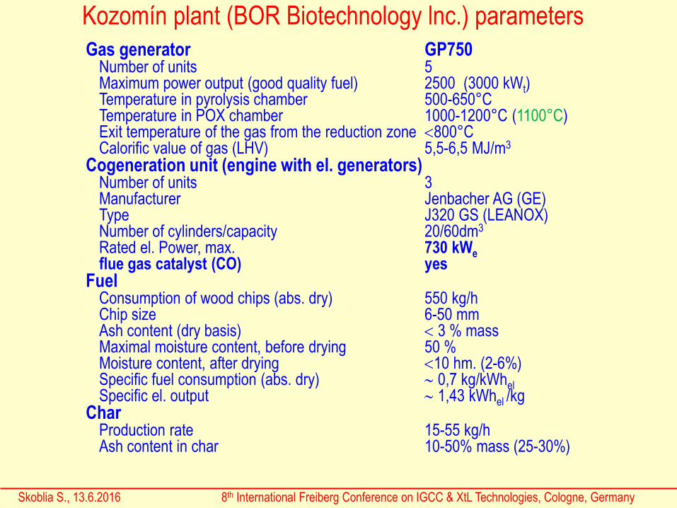
Gas generator GP750Number of units 5Maximum power output (good quality fuel) 2500 (3000 kWt)Temperature in pyrolysis chamber 500-650°C Temperature in POX chamber 1000-1200°C (1100°C)Exit temperature of the gas from the reduction zone 800°CCalorific value of gas (LHV) 5,5-6,5 MJ/m3
Cogeneration unit (engine with el. generators)Number of units 3Manufacturer Jenbacher AG (GE)Type J320 GS (LEANOX)Number of cylinders/capacity 20/60dm3
Rated el. Power, max. 730 kWeflue gas catalyst (CO) yes
FuelConsumption of wood chips (abs. dry) 550 kg/hChip size 6-50 mm Ash content (dry basis) 3 % massMaximal moisture content, before drying 50 %Moisture content, after drying 10 hm. (2-6%)Specific fuel consumption (abs. dry) 0,7 kg/kWhelSpecific el. output 1,43 kWhel /kg
CharProduction rate 15-55 kg/hAsh content in char 10-50% mass (25-30%)
Skoblia S., 13.6.2016 8th International Freiberg Conference on IGCC & XtL Technologies, Cologne, Germany
Kozomín plant (BOR Biotechnology lnc.) parameters

Skoblia S., 13.6.2016 8th International Freiberg Conference on IGCC & XtL Technologies, Cologne, Germany
Power plant Kozomín (Handlová, Dobříš), original flowsheet1
2
3
4
5
6
78
9
10
11
12
13
14
A1
A2
TAR
GAS
1 - entry of the fuel into the GP750, 2 - allothermal pyrolysis section, 3 - autothermal pyrolysis section, 4 - POX section,
5 - combustion flare, 6 - gas output, 7 - bag filter, 8 - heat exchangers (gas/water), 9 - contact water cooling, 10 - cooling
tower, 11 - gas blower, 12 - gas flow measurement , 13 - mix tank, 14 - pipe to IC motor.
A1-primary air inlet, A2- secondary air supply
GAS - point for gas quality sampling (on-line, off-line), TAR - point for gas sampling according to Tar Protocol

Skoblia S., 13.6.2016 8th International Freiberg Conference on IGCC & XtL Technologies, Cologne, Germany
1 - entry of fuel into the GP750, 2 - allothermal pyrolysis section, 3 - autothermal pyrolysis section, 4 - POX section,
5 - combustion flare, 6 - gas output, 7 - hot filters (CERAFIL XS 3000), 8 - heat exchangers (gas/water), 9 - contact water
cooling, 10 - cooling tower, 11 - gas blower, 12 - gas flow measurement , 13 - mix tank, 14 - pipe to IC motor
A1 - primary air inlet, A2 - secondary air supply
GAS - point for gas quality sampling (on-line, off-line), TAR-point for gas sampling according to Tar Protocol.
Power plant Kozomín (Handlová) after reconstruction, flowsheet1
2
3
4
5
6
7
89
10
11
12
13
14
A1
A2
TAR
GAS

Skoblia S., 13.6.2016 8th International Freiberg Conference on IGCC & XtL Technologies, Cologne, Germany
Generators hall (BOR Biotechnology lnc.)
generators hall with HF
Fuel dryingFuel feeder
Fuel storage
Jenbacher J320 GS
GP750 fuel feeder
HF
MIX tank

Skoblia S., 13.6.2016 8th International Freiberg Conference on IGCC & XtL Technologies, Cologne, Germany
Generators hall (BOR Biotechnology, lnc.)GP750 #5
HF
#5 #4
#3#2
#1
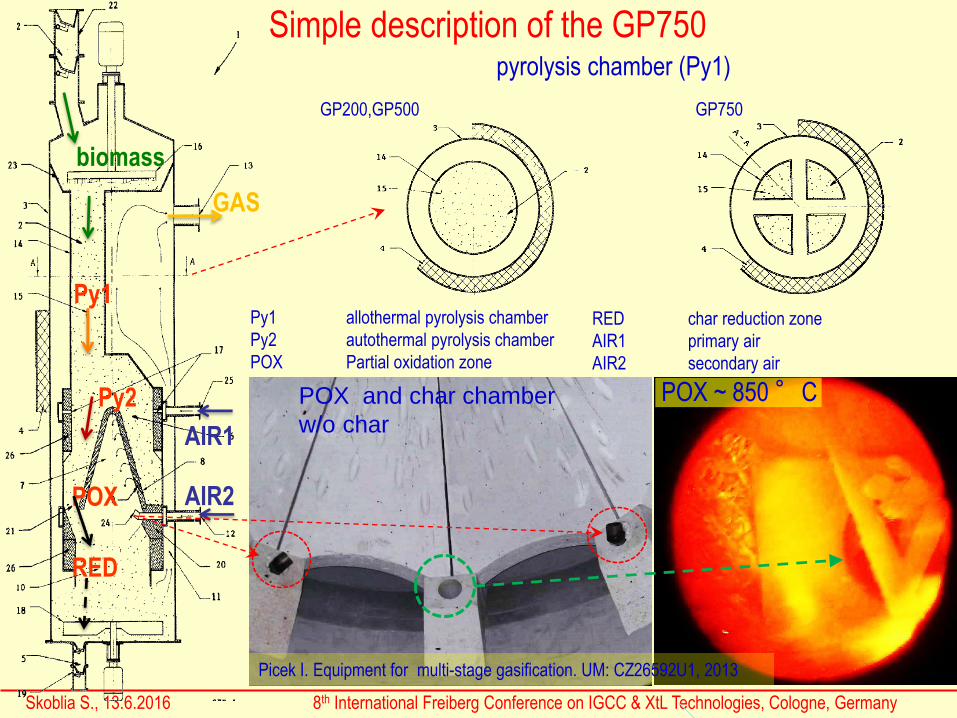
Simple description of the GP750
Skoblia S., 13.6.2016 8th International Freiberg Conference on IGCC & XtL Technologies, Cologne, Germany
POX and char chamber
w/o char
POX
RED
Py2
Py1
AIR1
AIR2
biomass
GAS
POX ~ 850 °C
Picek I. Equipment for multi-stage gasification. UM: CZ26592U1, 2013
Py1 allothermal pyrolysis chamber
Py2 autothermal pyrolysis chamber
POX Partial oxidation zone
pyrolysis chamber (Py1)
RED char reduction zone
AIR1 primary air
AIR2 secondary air
GP200,GP500 GP750

Skoblia S., 13.6.2016 8th International Freiberg Conference on IGCC & XtL Technologies, Cologne, Germany
Gas composition, Handlová (SK), 2014
Dust removal: fabric bag filters, 110-120°C
Final gas treatment: water washing/cooling tower
IC motors: Guascor, FBLD560,(56l, V16)
TAR sampling 1 2 3 4
TAR w/o BTX, mg/m3 26.5 98.7 57.5 28.5
Oxy TAR(F,mF,DBF), % 66 71 63 42
indene to fluoren,% 29 25 23 42
higher that phenan., % 0 0 0 0
rest, % 4 4 14 16
1 2 3 4
Skoblia S., 13.6.2016 8th International Freiberg Conference on IGCC & XtL Technologies, Cologne, Germany
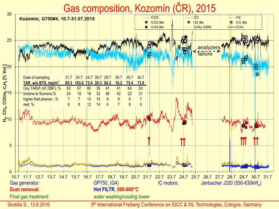
Gas composition, Kozomín (ČR), 2015
Date of sampling 21.7 24.7 24.7 29.7 29.7 29.7 30.7 30.7
TAR w/o BTX, mg/m3 85.3 163.0 73.4 20.3 84.3 19.2 75.4 73.8
Oxy TAR(F,mF,DBF), % 62 67 60 39 41 41 64 63
iindene to fluorene,% 24 18 18 32 46 42 22 21
higher that phenan., % 7 7 10 15 9 9 6 7
rest, % 8 8 12 14 4 7 8 9
Gas generator: GP750, (G4)
Dust removal: Hot FILTR, 500-600°C
Final gas treatment: water washing/cooling tower
IC motors: Jenbacher J320 (550-630kWe)

Skoblia S., 13.6.2016 8th International Freiberg Conference on IGCC & XtL Technologies, Cologne, Germany
Gas composition, Kozomín (ČR), 2016
Gas generator: GP750
Dust removal: Hot FILTR, 500-600°C
Final gas treatment: water washing/cooling tower
IC motors: Jenbacher J320 (550-630kWe)

Skoblia S., 13.6.2016 8th International Freiberg Conference on IGCC & XtL Technologies, Cologne, Germany
Fuel properties and their effects on generator operation
Proximate and
ultimate analysis
of selected fuels
*)chips stored for long period in the open air
fuel properties Handlová, 2014 Kozomín, 2015 Kozomín*), 2016 Kozomín, 2016
moisture,Wa 5.00 14.00 2.61 2.89
ash, Ad 1.08 2.78 1.03 0.98
volatile matter,Vd 79.75 78.80 78.84 78.21
fixed carbon, Fcd 19.17 18.42 20.14 20.81
Qia 16.94 14.72 16.71 17.23
Qidaf 18.16 18.02 17.40 17.99
ultimate analysis, d
C 49.58 50.28 48.62 48.40
H 6.30 6.15 5.88 6.08
N 0.50 0.27 0.23 0.19
O 42.52 40.48 44.24 44.34
S 0.02 0.04 0.01 0.01

Skoblia S., 13.6.2016 8th International Freiberg Conference on IGCC & XtL Technologies, Cologne, Germany
1) Determination of tar was carried out according to Tar Protocol. Given value does not contain toluene, xylenes and benzenes2) Air for gasification was preheated.
Composition of gas from co-current and staged gasifier
BOSS Imbert2)
100kWe
Co-current
GP3002)
Viking DTU
75 kWt
GP2002) GP5002) GP750
moisture, % hm. <10 <10 35-45 <10 <10 <10
CO 25,5 24,6 19,6 26,7 25,0 25,3
H2 17,2 16,4 30,5 23,0 22,3 22,7
CH4 3,0 2,2 1,2 1,1 2.00 1,3
CO2 9,6 9,6 15,4 8.00 9,4 9,7
N2(+Ar) 43,5 46,1 33,2 40,6 41,1 40,9
Other 1,2 1,1 0,1 0,6 0,2 0,1
Tar, mg/m3 1000-20001) 1300-20001) <5 0,5-2,01) 5,0-401) 20-2001)
Qi (15/15 °C) MJ/m3 6,3 5,7 5,6 5,9 5,9 5,8
The POX chamber size for different gasifiers
* Normal condition
Type POX chamber Volume Flow* R. T.*
D,m H,m m3 m3/h s
GP200 1,0 1,1 0,3 400 2,7
GP500 1,6 2,1 1,5 900 6
GP750 2,5 2,3 4,0 1400 10

Acknowledgement: Part of the presented work was accomplished thanks to the
financial support provided by the technological Agency of the Czech Republic, under
project No. TA04020583.
Thank you for your attention
We express our gratitude to the company BOR Biotechnology, Inc.,
(http://www.borbiotechnology.cz/en/contacts) that provided your commercials equipment
for experiments and greatly assist in their implementation.
Also, we thank the company Air Technic, Itd., (http://www.airtechnic.cz/kontakty.html),
that constructed and built the facility in Kozomín, provided necessary information and
assistance in the implementation of the experiments.
Special thanks belongs to the following people:
Ing. Lubomír Ondrůj
Ing. Martin Šimák
Ing. Oliver Garaj
Ing. Přemysl Kotouček
from BOR Biotechnology, ltd.
Skoblia S., 13.6.2016 8th International Freiberg Conference on IGCC & XtL Technologies, Cologne, Germany
Ing. Petr Jirkovský
Ing. Pavel Záhořík
Ing. Petr Fridrich
Ing. Roman Běloušek
Mr. Jan Bíma
from Air Technic, ltd.Ing. Stanislav Gurský
Mr. Pavel Dioszegi
from Handlovská Energetika ltd.
Ing. Ivo Picek
from Tarpo ltd.
Ing. Tomáš Svatoň
from ALA SENSORS ltd.