Embed Size (px)
DESCRIPTION
Exp 2 - Report
Citation preview
FACULTY OF PETROLEUM AND RENEWABLE ENERGY ENGINEERING
UNUNIIVVEERRSSIITITI TTEKEKNNOLOGIOLOGI MAMALLAYAYSSIIAA
FFLLUUIIDD MMEECCHHANANIICCSS LLAABOBORARATOTORRYY
TITLE OF EXPERIMENT
STABILITY OF FLOATING BODY (E 2)
Name MUHAMMAD KHAIRIL IKRAM(A13KP0047)
AKMAL FAIZ BIN ABDUL RAHIM (A13KP0008)
ABDUL WAHAB (A13KP4006)
KSATRIYA ANANTAYUTYA (A13KP4001)
Group / Section 1/Section
Supervisor Associate Professor Issham bin Ismail
Date of Experiment 3/3/2014
Date of Submission 9/3/2014
Marks obtained (%)
REPORT SUMMARY
The report is prepared for the sake of discussing about the principle in fluid mechanics which is the
stability of floating body which relates to the concept of centre of gravity and the location centre of
buoyancy. The appropriate location these two are matters since they will determine whether or not
a random floating body is either stable or not when placed in water. By theory, we know that when
the centre of buoyancy point of the body is higher/same than the centre of gravity, hence the body
is in neutral stability while if the case is opposite, otherwise will happen. Hence, the experiment is
conducted to prove this theory and according to the analysis prepared ,the theory is proven to be
correct.
INTRODUCTION
Laboratory experiment 2 is an exercise in hydrostatics. It is designed to demonstrate the stability
of a floating cylinder and to familiarize the student with the concept of buoyancy, metacenter, and
metacentric height. It is also an experimental verification of the theory presented in the textbook.
The center of the buoyancy (C, the centroid of the displaced volume of fluid) of a floating body
depends on the shape of the body and on the position in which it is floating. If the body is disturbed
by a small angle of heel, the center of buoyancy changes because the shape of the submerged
volume is changed. The point of intersection of the lines of action of the buoyancy force before and
after heel is called the metacenter (M) and the distance between the center of gravity (G) and M, is
called the metacentric height (GM,
PROCEDURE
. 1 The horizontal weight is taken out and the vertical weight is fixes on the mast of the pontoon
2. The thread is adjusted until it gives an angle of zero degree (no tilt).
3. The centre of gravity is determined by putting the pontoon mast on the mass balance. The
length of CG which is the length (in mm) is measured from the middle of mast to the base
pontoon.
4. The horizontal weight is fixed. The thread is made sure to be at zero mm (no tilt).
5. The tank is filled with water. Then, the pontoon is let to float in the tank.
6. Next, the length of the pontoon which was submerged in the water is measured.
7. After that, the horizontal weight is moved 10 mm to the right and the angle of tilt of the
thread is recorded.
8. The above step is repeated by using the horizontal weight 10 mm to the right. The angle of
tilt is recorded. This step is repeated until the plump bob which is hanging on the thread
touches the side of the pontoon.
9. The procedure is repeated by moving the horizontal weight to the left side.
10. The height of the vertical weight is adjusted to new height and procedures no. 7, 8, and 9
are repeated. The test is done at two (2) values of vertical heights.
Theory :-
Symbols :-W = total mass of pontoon with the vertical weight (kg)w = mass of horizontal weight (kg)GM = height of meta-center (mm)θ = angle of tilt (degrees)x = distance by which the horizontal weight is moved (mm)I = second moment of water surface area at vertical axis (mm4)L = length of pontoon (mm)B = width of pontoon (mm)V = volume of displaced water (mm3)BM = length between center of body and meta-centery = the distance between the base of pontoon to the center of gravity
Given Data :-Mass of horizontal weight = 0.28078 kgTotal mass of pontoon with vertical weight = 1.16567 kgWidth of pontoon = 200 mmLength of pontoon = 350 mmHeight = 75 mm
If a horizontal weight is moved a distance “x” from the center, the pontoon will tilt. The angle of tilt can be measured by using the plumb bob.
Overturning couple, Co = wgxRighting couple, Cr = Wg(GM) tan θ
For equilibrium, Co = Cr then GM = wx / (W tan θ)
Calculation using area of second moment:-
BM = I/V, where I = LB3 /12 and V= W/
Thus, GM = BM – BG = BM – y + d/2
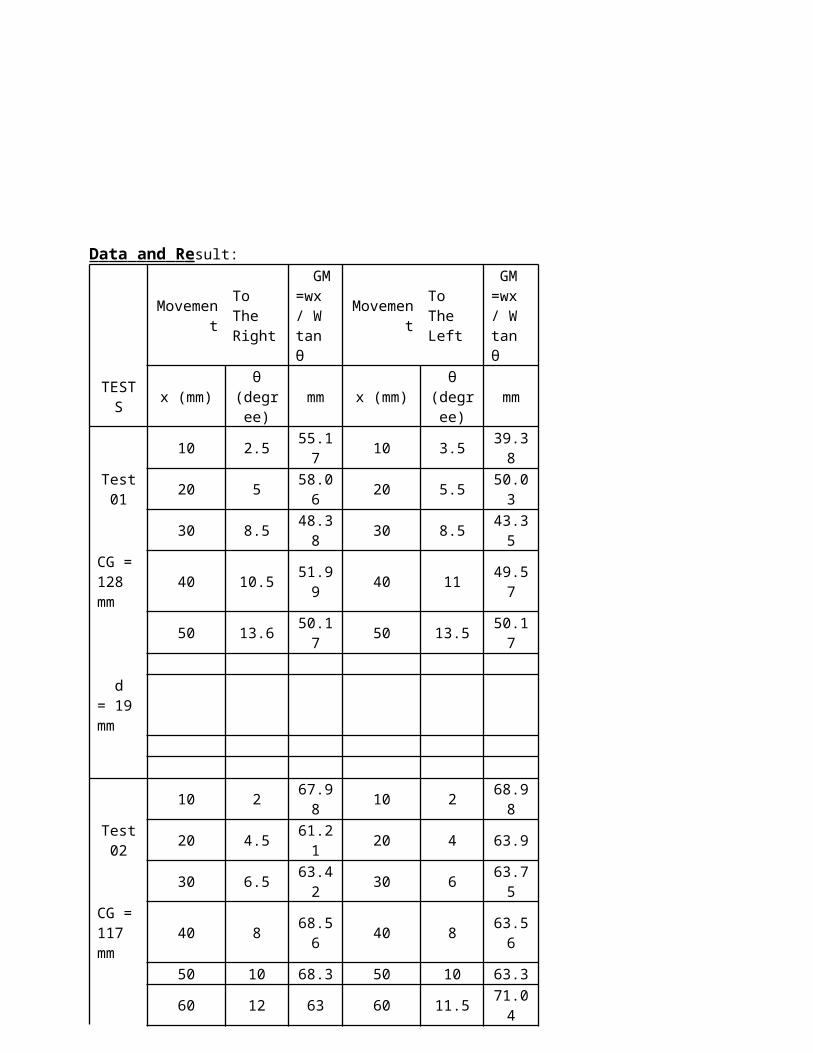
D a ta a nd R e sult:
Movement To The Right
GM =wx / W tan θ
Movement To The Left
GM =wx / W tan θ
TESTS x (mm)θ
(degree)mm x (mm)
θ (degree)
mm
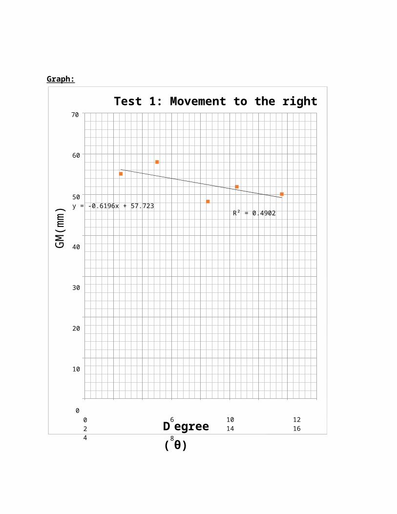
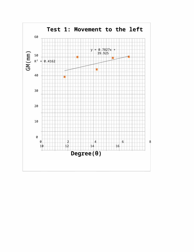
10 2.5 55.17 10 3.5 39.38Test 01
20 5 58.06 20 5.5 50.03
30 8.5 48.38 30 8.5 43.35CG = 128 mm
40 10.5 51.99 40 11 49.57
50 13.6 50.17 50 13.5 50.17
d = 19 mm
10 2 67.98 10 2 68.98Test 02
20 4.5 61.21 20 4 63.9
30 6.5 63.42 30 6 63.75CG = 117 mm
40 8 68.56 40 8 63.56
50 10 68.3 50 10 63.3
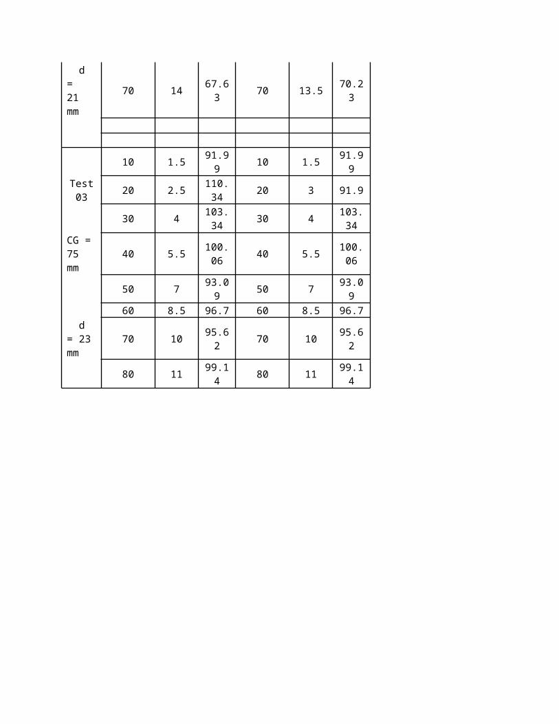
60 12 63 60 11.5 71.04 d = 21 mm
70 14 67.63 70 13.5 70.23
10 1.5 91.99 10 1.5 91.99Test 03
20 2.5 110.34 20 3 91.9
30 4 103.34 30 4 103.34CG = 75 mm
40 5.5 100.06 40 5.5 100.06
50 7 93.09 50 7 93.09
60 8.5 96.7 60 8.5 96.7 d = 23 mm
70 10 95.62 70 10 95.62
80 11 99.14 80 11 99.14
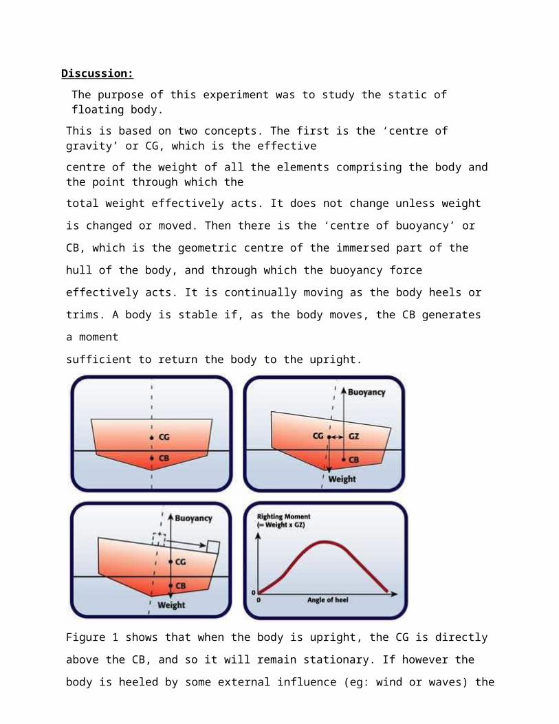
Dis c ussion:
The purpose of this experiment was to study the static of floating body.
This is based on two concepts. The first is the ‘centre of gravity’ or CG, which is the effective
centre of the weight of all the elements comprising the body and the point through which the
total weight effectively acts. It does not change unless weight is changed or moved. Then there
is the ‘centre of buoyancy’ or CB, which is the geometric centre of the immersed part of the hull
of the body, and through which the buoyancy force effectively acts. It is continually moving as
the body heels or trims. A body is stable if, as the body moves, the CB generates a moment
sufficient to return the body to the upright.
Figure 1 shows that when the body is upright, the CG is directly above the CB, and so it will
remain stationary. If however the body is heeled by some external influence (eg: wind or waves)
the CB moves to one side, thus generating a restoring moment about the CG – see Figure 2. The
further the CB moves for a given heel angle, the greater the tendency to return to the upright. The
size of the ‘righting moment’ is the weight of the body multiplied by the distance GZ as shown
in
Figure 2, which is sometimes known as the ‘righting lever’.

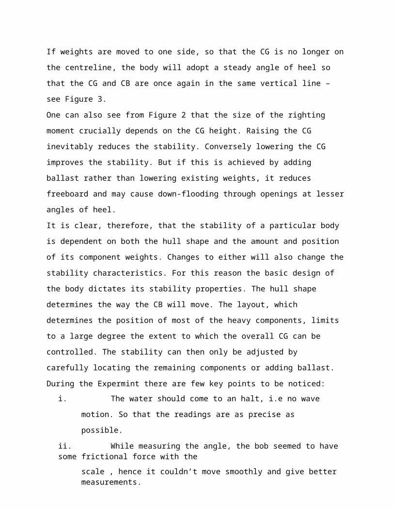
If weights are moved to one side, so that the CG is no longer on the centreline, the body will
adopt a steady angle of heel so that the CG and CB are once again in the same vertical line – see
Figure 3.
One can also see from Figure 2 that the size of the righting moment crucially depends on the CG
height. Raising the CG inevitably reduces the stability. Conversely lowering the CG improves
the stability. But if this is achieved by adding ballast rather than lowering existing weights, it
reduces freeboard and may cause down-flooding through openings at lesser angles of heel.
It is clear, therefore, that the stability of a particular body is dependent on both the hull shape and
the amount and position of its component weights. Changes to either will also change the
stability characteristics. For this reason the basic design of the body dictates its stability
properties. The hull shape determines the way the CB will move. The layout, which determines
the position of most of the heavy components, limits to a large degree the extent to which the
overall CG can be controlled. The stability can then only be adjusted by carefully locating the
remaining components or adding ballast.
During the Expermint there are few key points to be noticed:
i. The water should come to an halt, i.e no wave motion. So that the readings are as
precise as possible.
ii. While measuring the angle, the bob seemed to have some frictional force with the
scale , hence it couldn’t move smoothly and give better measurements.
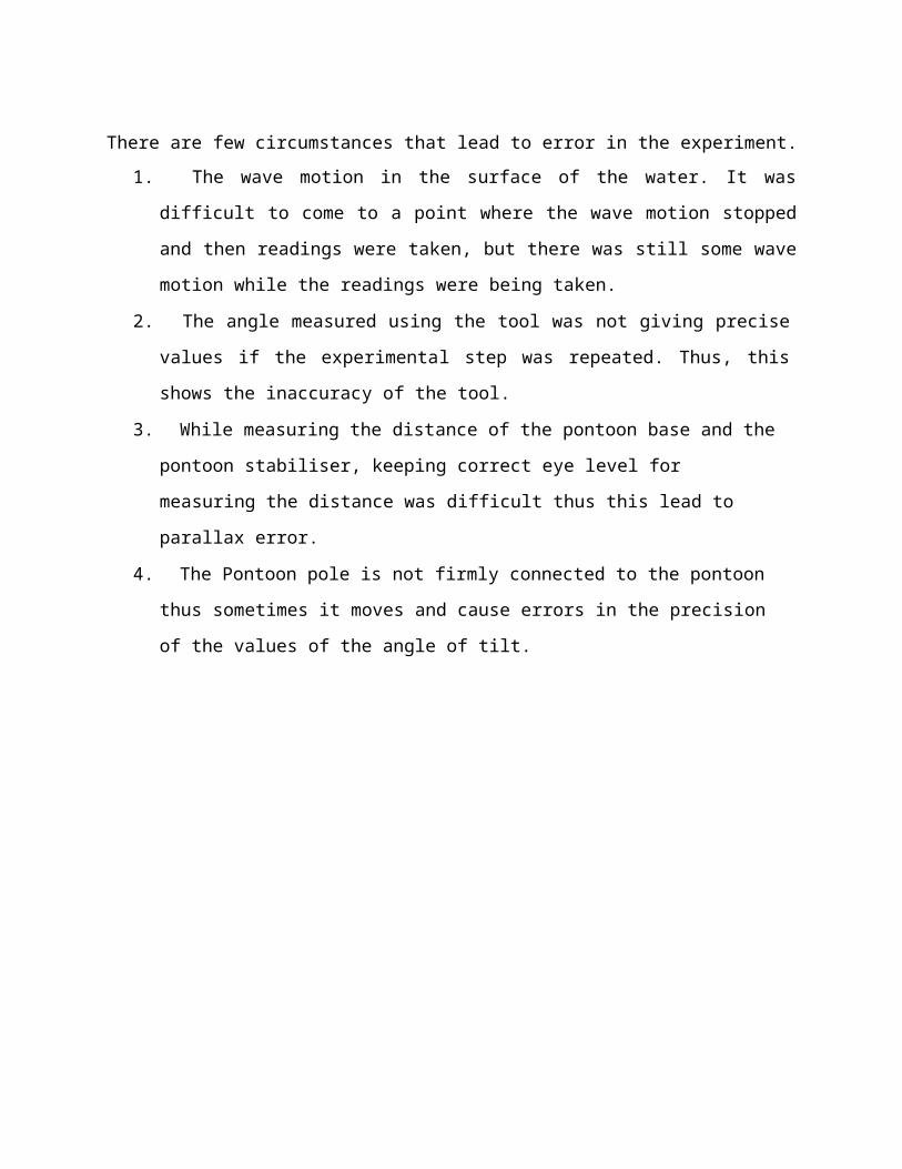
There are few circumstances that lead to error in the experiment.
1. The wave motion in the surface of the water. It was difficult to come to a point where the
wave motion stopped and then readings were taken, but there was still some wave motion
while the readings were being taken.
2. The angle measured using the tool was not giving precise values if the experimental step
was repeated. Thus, this shows the inaccuracy of the tool.
3. While measuring the distance of the pontoon base and the pontoon stabiliser, keeping
correct eye level for measuring the distance was difficult thus this lead to parallax error.
4. The Pontoon pole is not firmly connected to the pontoon thus sometimes it moves and
cause errors in the precision of the values of the angle of tilt.
GM
(mm
)Graph:
70
Test 1: Movement to the right
60
50 y = -0.6196x + 57.723R² = 0.4902
40
30
20
10
00 2 4
D6egree(
8
θ)
10 12 14 16
GM
(mm
)Test 1: Movement to the left
60
y = 0.7827x + 39.92550 R² = 0.4162
40
30
20
10
00 2 4 6 8 10 12 14 16
Degree(θ)
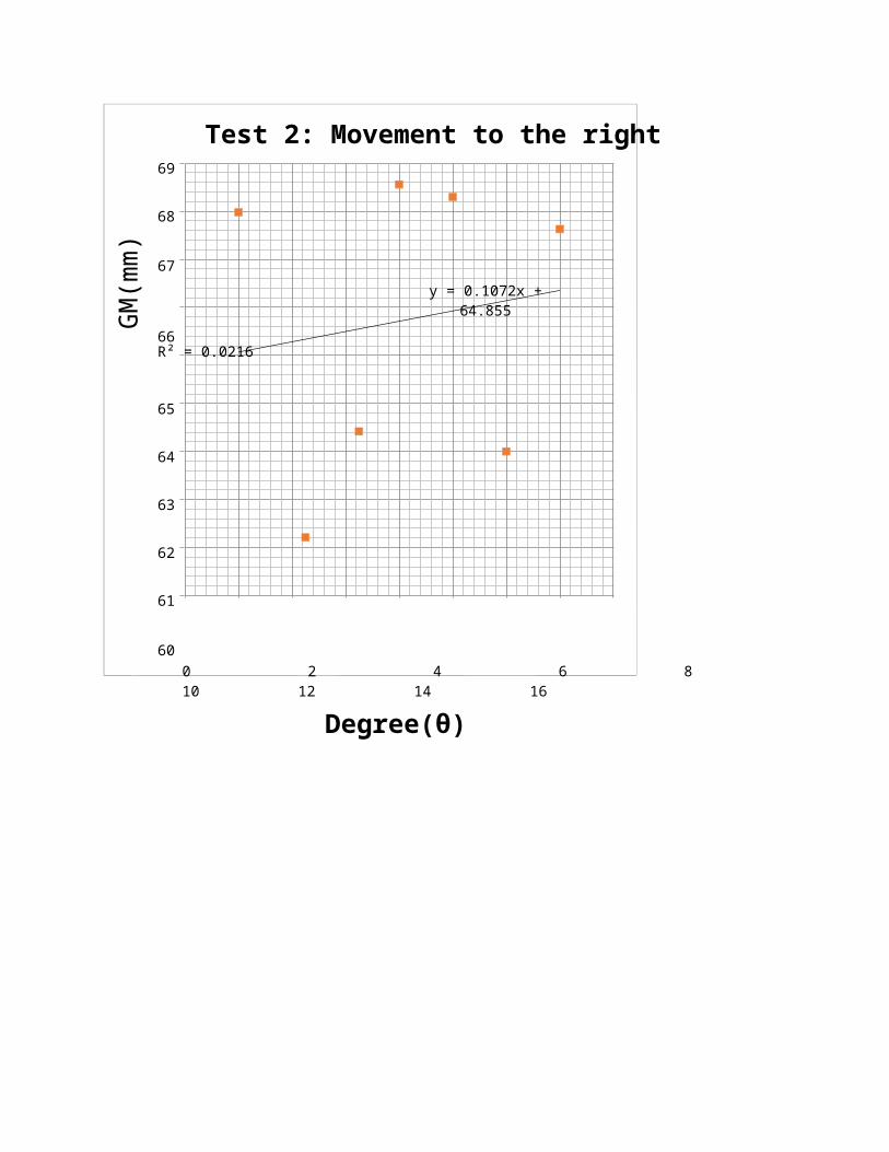
GM
(mm
)Test 2: Movement to the right
69
68
67
y = 0.1072x + 64.855
66 R² = 0.0216
65
64
63
62
61
600 2 4 6 8 10 12 14 16
Degree(θ)
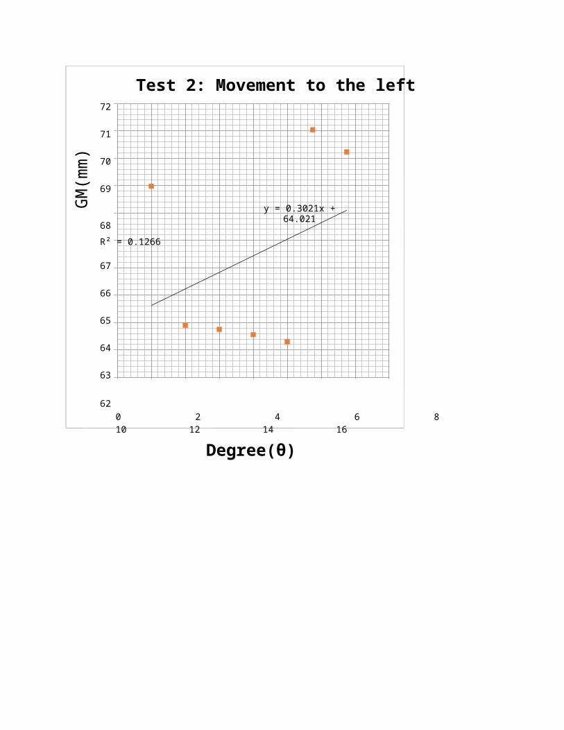
GM
(mm
)Test 2: Movement to the left
72
71
70
69
y = 0.3021x + 64.02168 R² = 0.1266
67
66
65
64
63
620 2 4 6 8 10 12 14 16
Degree(θ)
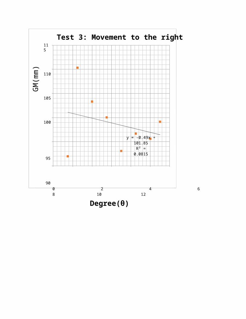
GM
(mm
)115
Test 3: Movement to the right
110
105
100
y = -0.49x + 101.85R² = 0.0815
95
900 2 4 6 8 10 12
Degree(θ)
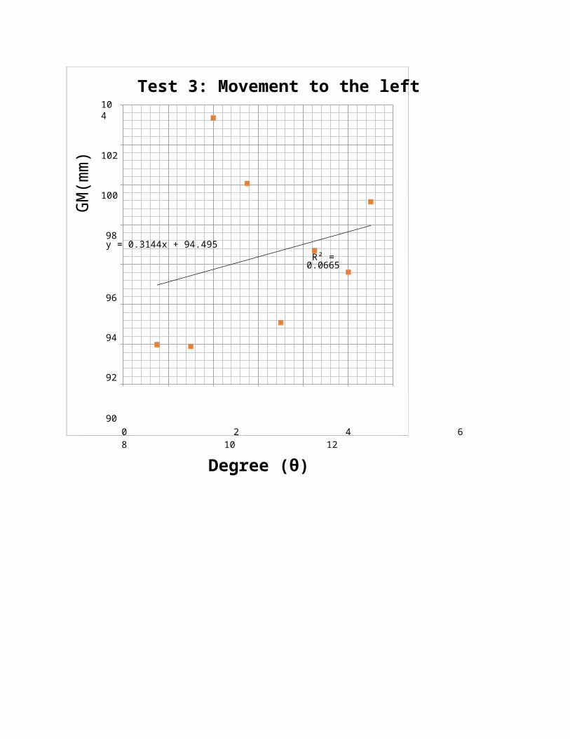
GM
(mm
)104
Test 3: Movement to the left
102
100
98 y = 0.3144x + 94.495R² = 0.0665
96
94
92
900 2 4 6 8 10 12
Degree (θ)
Conclusion:
From this experiment, we can made three conclusions. Firstly, the position of meta-centric, M
for the body is changing according to the position of the body gravity center. Secondly, the
position of meta-centric, M is also changing according to the angle, θ. Next, the location of
meta-center is change according to the tilt angle and inversely proportional to the tilt angle. The
meta-centric position, M is linear to 1/θ. The position of meta-center will change according to
the angle from the equation,
Meta-centric position,
The position of meta-center of the body is linear with 1/ θ, in which when the value of θ
becomes smaller, the value of GM become greater and it is the same for the opposite situation.
Reference:
Rolf H. Sabersky, Allan J Acosta, Edward G. Hauptmann and E.M. Gates, "Fluid Flow-A First
Course of Fluid Mechanics" (Fourth Edition), Prentice Hall Inc., 1999.
5.Monsun B. R. Fundamentals of Fluid Mechanics. USA :John Wiley & Sons, Inc, 1994.
R.V Giles, “Fluid Mechanics and Hydraulics” (Third Edition), McGrawHill Inc; 1994.
Lab Manual University Teknologi Malaysia.
4.Robert A. Granger. ‘Experiments in Fluid Mechanics’.Holt, Rinehart and Winston, Inc. NewYork. 1988.
Appendices
LIST OF SYMBOLS
B Center of buoyancy
B’ Displaced center of buoyancy
d Transverse distance of displacement of added mass
FB Buoyancy force or upthrust
G Center of gravity of floating body
G’ Displaced center of gravity of floating body
G1 Displaced center of gravity of floating body with free surface
GZ Moment arm of restoring couple
g Acceleration due to gravity
IOy Second moment of area of plane of floatation about its longitudinal axis
i Second moment of area for free surface tank
K Keel
KOy Mass radius of gyration of floating body about its longitudinal axis
M Transverse metacenter
m Mass
T Period of oscillation
W Weight of floating body
Greek Symbols:
Angle of heel or inclination
Density of seawater
f Density of liquid in tank
Calculation Example:
To get height of meta-center (mm), we use the equation,
GM = wx / W tan θ ,
w = 0.28078 kg
W= 1.16567 kg
x = 10.0 mm ( taken from Test 01 movement to the right)
θ = 1.50 o
Then,
GM = (0.28078 kg x 10 mm) / (1.16567 kg x tan 1.50 o)
= 91.9862 mm
This calculation has been repeated to gain a data as stated in schedule.