Embed Size (px)
Citation preview
Julia Thorpe Landscape Building at Janelia Farm Mechanical Option Final Report
11
E X I S T I N G M E C H A N I C A L C O N D I T I O N S
SYSTEM LOCATION
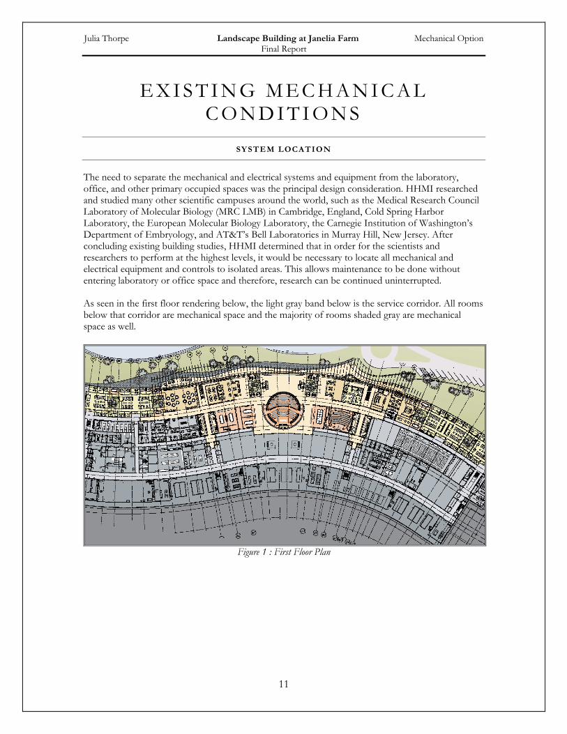
The need to separate the mechanical and electrical systems and equipment from the laboratory, office, and other primary occupied spaces was the principal design consideration. HHMI researched and studied many other scientific campuses around the world, such as the Medical Research Council Laboratory of Molecular Biology (MRC LMB) in Cambridge, England, Cold Spring Harbor Laboratory, the European Molecular Biology Laboratory, the Carnegie Institution of Washington’s Department of Embryology, and AT&T’s Bell Laboratories in Murray Hill, New Jersey. After concluding existing building studies, HHMI determined that in order for the scientists and researchers to perform at the highest levels, it would be necessary to locate all mechanical and electrical equipment and controls to isolated areas. This allows maintenance to be done without entering laboratory or office space and therefore, research can be continued uninterrupted. As seen in the first floor rendering below, the light gray band below is the service corridor. All rooms below that corridor are mechanical space and the majority of rooms shaded gray are mechanical space as well.
Figure 1 : First Floor Plan
Julia Thorpe Landscape Building at Janelia Farm Mechanical Option Final Report
12
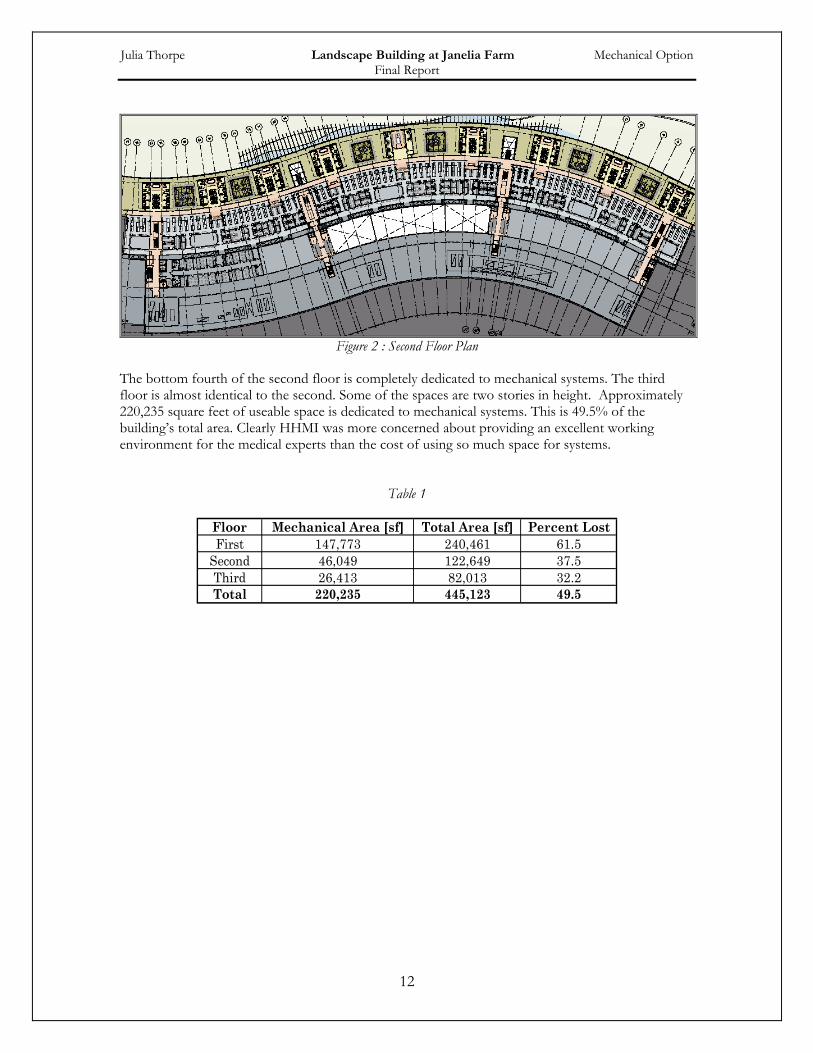
Figure 2 : Second Floor Plan
The bottom fourth of the second floor is completely dedicated to mechanical systems. The third floor is almost identical to the second. Some of the spaces are two stories in height. Approximately 220,235 square feet of useable space is dedicated to mechanical systems. This is 49.5% of the building’s total area. Clearly HHMI was more concerned about providing an excellent working environment for the medical experts than the cost of using so much space for systems.
Table 1
Floor Mechanical Area [sf] Total Area [sf] Percent LostFirst 147,773 240,461 61.5
Second 46,049 122,649 37.5Third 26,413 82,013 32.2Total 220,235 445,123 49.5
Julia Thorpe Landscape Building at Janelia Farm Mechanical Option Final Report
13
DESIGN OBJECTIVES
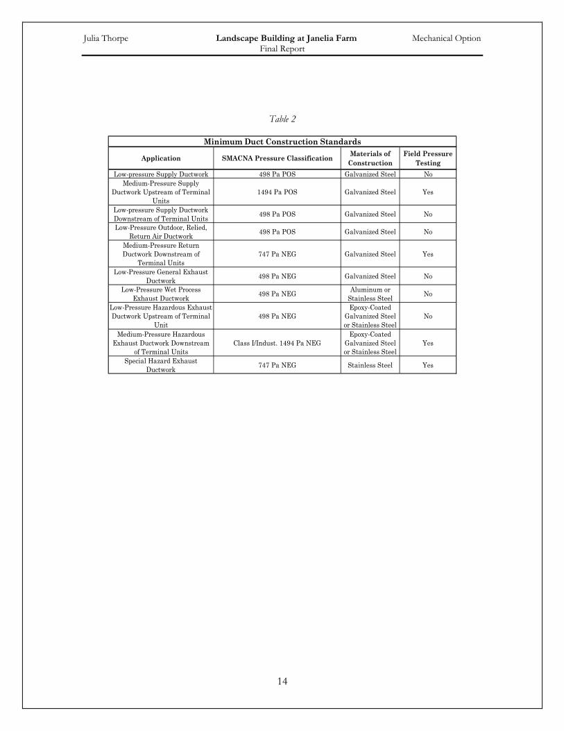
Central boiling and chiller plants are used to provide central heating and cooling to the entire building. The data rooms are the only spaces that have a parallel system to meet cooling loads. Due to the nature of the building, 100 percent outdoor air is required to dilute any hazardous matter in the air and to decrease the risk of contamination between spaces. Supply air must pass through a prefilter and filer on the upstream side with efficiencies of 30% and 95% respectively, based on ASHRAE Standard 52-76. The system has pressure-independent hot water terminal reheat variable air volume terminals and individual laboratory and office area temperature zone control. The system is also designed to maintain the proper temperature, humidity, differential pressure, outdoor air exchange rate, and acoustic criteria within the building. The laboratory spaces are arranged with supply air distributed by multiple air handlers to ensure that fresh air is supplied 100% of the time. This concept is also applied to the exhaust fans. If one piece of equipment is not working properly or needs to be serviced, the load can be transferred to other equipment. Concentrations can be determined using methodology outlined in National Institutes of Health’s (NIH) HVAC Requirements. The facility is in the process of recruiting the very best scientists from around the world including six Nobel Prize winners at present. The research projects are centered on test mice housed in the Vivarium. The multimillion dollar mice are to be provided with excellent living environments due to ensure their health and accurate test result. The required air flow to the Vivarium spaces is not based on occupancy or space type, but the necessary air changes per hour. In addition, the animals housed in the Vivarium require warmer temperatures than do people. Accordingly, the supply air is reheated to 64oF supplied 24 hours per day. Individual control is provided to each holding room, treatment room, procedures room, and operating room. The Vivarium facilities are serviced by AHU-1, AHU-2, and AHU-3(back-up) that run in parallel to heat, ventilate and provide air-conditioning. The arrangement with stand-by equipment ensures continuous operation during equipment failure and scheduled maintenance. Supply air is introduced through high-volume and uniformly drawn across the holding areas to provide uniform mixing. It is important to ensure that the system does not create drafts on the animals. The mice are involved with chronic testing which presents serious complications if people or other animals are exposed. As a result, HEPA filters are required in the exhaust air ducts. Ventilation Design Handbook on Animal Facility and Animal Facility design published by NIH and ASHRAE Application Handbook were used to design the Vivarium system. Mechanical, electrical, elevator machine, boiler, and cage wash equipment spaces are conditioned to ensure worker comfort, to increase equipment life, and to avoid excessive heat gains/losses to adjacent occupied areas. In compliance with NFPA Standard 90A exhaust ducts are not located in the same shaft supply and/or return air ducts. All toilet and general exhaust is discharged using systems in independent of the lab exhaust systems. For information about exhaust and/or supply duct material, please see Table 2 based on NIH Requirements.
Julia Thorpe Landscape Building at Janelia Farm Mechanical Option Final Report
14
Table 2
Application SMACNA Pressure Classification Materials of Construction
Field Pressure Testing
Low-pressure Supply Ductwork 498 Pa POS Galvanized Steel NoMedium-Pressure Supply
Ductwork Upstream of Terminal Units
1494 Pa POS Galvanized Steel Yes
Low-pressure Supply Ductwork Downstream of Terminal Units 498 Pa POS Galvanized Steel No
Low-Pressure Outdoor, Relied, Return Air Ductwork 498 Pa POS Galvanized Steel No
Medium-Pressure Return Ductwork Downstream of
Terminal Units747 Pa NEG Galvanized Steel Yes
Low-Pressure General Exhaust Ductwork 498 Pa NEG Galvanized Steel No
Low-Pressure Wet Process Exhaust Ductwork 498 Pa NEG Aluminum or
Stainless Steel No
Low-Pressure Hazardous Exhaust Ductwork Upstream of Terminal
Unit498 Pa NEG
Epoxy-Coated Galvanized Steel or Stainless Steel
No
Medium-Pressure Hazardous Exhaust Ductwork Downstream
of Terminal UnitsClass I/Indust. 1494 Pa NEG
Epoxy-Coated Galvanized Steel or Stainless Steel
Yes
Special Hazard Exhaust Ductwork 747 Pa NEG Stainless Steel Yes
Minimum Duct Construction Standards
Julia Thorpe Landscape Building at Janelia Farm Mechanical Option Final Report
15
SYSTEM DESIGN & OPERATION
AIR SYSTEMS
The mechanical system uses a variable air volume (VAV) distribution system. As stated above, 100 percent outdoor air is required at all times. The building is served by 15 identical custom type 45,000cfm air handling units; 14 primary and one back-up. All 15 air handling units feed into one plenum which serves the entire building. AHU-1 and AHU-2 are separated from the rest of the air handlers by volume dampers. They serve the Vivarium during typical operations with AHU-3 serving as back-up. AHU-4 thought AHU-15 serve the rest of the building through one plenum. If needed, AHU-1,2 & 3 can also be connected in parallel with the rest of the units. Lab and Vivarium spaces will receive 100% outdoor air and pass through 30% efficient prefilters, 95% efficient final filters, energy recovery coils, direct injection steam humidifiers, chilled water cooling coils, and single plenum-type fans. The supply fans operate at 88.5 BHP and the AHU supply temperature is 45.8oF. The system has pressure-independent hot water variable air volume with reheat terminal devices and individual laboratory and office area temperature zone control. Outdoor air inlet dampers in each plenum open to bring in outdoor air to mix with exhaust air to maintain a constant discharge velocity from each exhaust stack with exhaust air volume demand decreases. All radio-chemistry or perchloric acid hoods are located on the third level of the Landscape Building and are equipment with dedicated direct exhaust to the roof. All occupied spaces are equipped with climate control which is accomplished by variable air volume terminal unit and reheat coil. Air volumes are throttled to minimum flow rate before the reheat coils are activated to heat the space. Fan powered air terminal units with reheat coil are installed in the office areas where occasional, minimal cooling requirements would result in air flows that are sufficiently low to cause air quality problems.
CHILLED WATER & STEAM
The estimated demand for each utility is 23,210 kW (6600tons) for chilled water and 26,000 kW (100,000 lb/hr) for steam. Electricity is supplied by Dominion Power. The chilled water and steam enters the lower level of the Landscape Building via the utility tunnel. There is a two-stage pressure-reducing station that supplies medium pressure steam for sterilizers, washers, and other scientific equipment. Secondary chilled water and return chilled water from air handling unit cooling coils are used for lab equipment cooling and environmental room condensers.
HYDRONIC HEATING
Heat exchangers provide hot water for variable air volume terminal reheat coils, cabinet heaters, and convectors. These units are used for secondary heating throughout the building. There are dedicated circulation variable frequency drives for each heat exchanger as well as one redundant heat exchanger/pump combination.
Julia Thorpe Landscape Building at Janelia Farm Mechanical Option Final Report
16
BOILER PLANT
The boiler plant contains three boilers and room for an addition of a fourth. Two have a capacity of 50,210 MBH and one is 30,125 MBH; a total energy input is 163,181 MBH. All three boilers have an 80% efficiency. They make 80 lbs steam and convert it to 15 lbs steam when needed. In general, two boilers run in any combination to meet desired load. The majority of the steam generated by the boilers is used by the air handler steam coils. Any remaining steam is used with the shell and tube heat exchangers (see TableA.8) XR-1 and XR-2 (back-up) are used to heat water that is pumped to reheat coils in the VAV boxes and XR-3 and XR-4 (back-up) used to heat water that is pumped to the radiant flooring in the lobby area.
CHILLER PLANT
There are six w/c centrifugal chillers and one back-up that have full load capacity of 1,200 tons each. The full load LCHWT and ECWT are 42.0oF and 85.0oF respectively. The full load power is 0.670 kW/ton. The condenser flow rate is 2,400 gpm and pressure drop of 13.0 ft. Remaining capacity is used for various equipment, such as the fan coil units in the data center room.