Embed Size (px)
Citation preview

Exhibit A: April 12, 2013, Letter from Tetra Tech toMassDEP(the "April 12, 2013 Supplement")

TETRATECH
Lit
April 12, 2013
Mr. James Belsky, Permit ChiefMassDEP Northeast Region205B Lowell StreetWilmington, MA 01887
Re: First Supplement to Major Comprehensive Plan Application —Salem Harbor Redevelopment (SHR) Project (Transmittal Number X254064)
Dear Mr. Belsky:
This first supplement to the Major Comprehensive Plan Application submitted on December 21,2012 is being submitted on behalf of Footprint Power Salem Harbor Development LP("FootprinC), and is based on comments provided by MassDEP in our meetings held in youroffices on February 26, 2013 (for air quality related topics) and March 12, 2013 (for noise relatedtopics). MassDEP requested that the following additional items be provided in a supplement tothe Plan Application:
1. Additional justification for use of existing ambient monitoring data in lieu of ofpreconstruction monitoring and the selection of background concentrations used in the airquality impact analyses, considering the recent appeals court decision which vacated theSignificant Monitoring Concentration (SMC) for PM2 5
2. An adjustment to the ambient impact analysis for PM2.5 or additional justification for theapproach taken to the impact analysis which included the use of the PM25 SIL,considering the recent appeals court decision which vacated and remanded portions of therules addressing the Significant Impact Level (SIL) for PM2.5
3. Additional justification for the selection of LAER and BACT for certain sources ofcriteria pollutants: a) the LAER emission rate for NO„ from the combustion turbines, andb) the BACT emission rate for VOC emission from the combustion turbines during ductfiring.
4. Additional justification for the selection of the BACT emission rate for CO2 emissionsincluding: a) additional cost information on carbon capture and sequestration, b)comparative turbine heat rates, and c) the cost implications and energy benefits of thevarious potential improvements suggested by DOER
5. Additional information on start-up emissions and durations and all emissions expressedon an energy output basis (in units of lb/MW-hr)
160 Federal Street, 3rd Floor, Boston, MA 02110'Tel 617.443.7500 Fax 617.737.3480
www.reci cam

Mr. James Belsky, Permit Chief Page 2
6. A more robust determination in accordance with the condition specified in 310 CMR 7.00Appendix A that "by means of an analysis for alternative sites, sizes, productionprocesses, and environmental control techniques" the Proponent shall demonstrate that"the benefits of the proposed source significantly outweigh the environmental and socialcosts imposed as a result of its location, construction, or modification."
7. An update on the status of obtaining the required emissions offsets
8. Final air quality impact modeling based on the plant with the selected turbine vendor andfinal site configuration and including GE Lynn and Wheelabrator Saugus as interactingsources for PM and NO, and Rousselot, Peabody Municipal Light, and MarbleheadMunicipal Light as interacting sources for 1-hour NOx
9. A more detailed analysis of federal environmental justice (EJ) considerations in supportof the PSD application
10. Documentation of the notifications provided to other federal agencies and the tribalcouncils as stipulated in the delegation agreement for the PSD Program betweenMassDEP and EPA Region 1
11. An updated assessment of background noise levels including a review of other recentsound measurement data that have been collected in the vicinity of the study area
12. A more detailed assessment of construction noise impacts and potential mitigationtechniques
13. Noise specifications for key plant equipment
14. Final acoustic modeling for the facility based on the turbine vendor selected, and the finalsite layout and noise mitigation plan
15. Vendor acoustic data for key plant equipment used in the final acoustic modeling
16. A more robust analysis of the costs and benefits of alternative noise mitigation techniques
All of the items listed above are addressed in this Plan Application supplement with theexception of the final air quality and acoustic modeling (items 8 and 14) and federal EJ, vendoracoustic data, and alternative noise mitigation technique analyses (items 9, 15, and 16) all ofwhich depend on final turbine vendor selection and/or final modeling. Certain energy efficiencymeasures per item 4.b are also still under evaluation. The final turbine vendor selection isexpected in late April or early May with final air and acoustic modeling anticipated to take placein May. The supplement containing these remaining five items is therefore currently expected tobe submitted in late May.
TETRA TECH

Mr. James Belsky, Permit Chief Page 3
The MassDEP-requested items are addressed in the sections below.
1. Additional justification for use of existing monitoring data in lieu of preconstructionmonitoring and the selection of background concentrations used in the air qualityimpact analyses, considering the recent appeals court decision which vacated theSignificant Monitoring Concentration (SMC) for PM2.5
As described in the SHR Project CPA application, representative and conservative monitoring
data are available and have been used to characterize criteria pollutant ambient background
concentrations for the project area (see Table 6-10 of the CPA). PSD regulations allow that a
regulatory authority may allow proposed sources to use existing monitoring data in lieu of PSD
preconstruction monitoring requirements for a pollutant if the source can demonstrate that its
ambient air impact is less than a de minimis amount (also called a significant monitoring
concentration or SMC) as specified in the regulations. As shown in Table 1 below, dispersion
modeling conducted for the SHR Facility predicted maximum impact concentrations well below
corresponding SMC levels for all pollutants for which SMCs currently exist.
Table 1 - Comparison of Maximum SHR Project Impacts to SMCs.
Pollutant AveragingPeriod
MaximumPredicted Impact(µg/m3)
Significant MonitoringConcentration (µg/m3)
NO2 Annual 0.6 14
CO 8-hour 213.4 575
SO2 24-hour 0.7 13
PMio 24-hour 5.4 10
EPA had also established a SMC for PM25 but this SMC was remanded by the United States
Court of Appeals for the DC Circuit on January 22, 2013 (No. 10-1413, Sierra Club v. EPA).
PSD regulations also allow that project-specific preconstruction monitoring may not be required
for a project if existing representative monitoring data are available and the Appeals Court
decision does not change this provision. On March 4, 2013, EPA Office of Air Quality Planning
and Standards issued guidance to applicants and regulators with regard to the ramifications of the
January 22, 2013 Appeals Court decision. The pertinent excerpt of this recent EPA guidance is
as follows:
As a result of the Court's decision, federal PSD permits issued henceforth by either theEPA or a delegated state permitting authority pursuant to 40 CFR 52.21 should not relyon the PM2.5 SMC to allow applicants to avoid compiling air quality monitoring data forPM2.5. Accordingly, all applicants requesting a federal PSD permit, including thosehaving already applied for but have not yet received the permit, should submit ambient
TETRATECH

Mr, James Belsky, Permit Chief Page 4
PM7.5 monitoring data in accordance with the Clean Air Act requirements whenevereither direct PM2.5 or any PM2,5precursor is emitted in a significant amount. In lieu ofapplicants setting out P1412,5 monitors to collect ambient data, applicants may submitPM 75 ambient data collected from existing monitoring networks when the permittingAuthority deems such data to be representative of the air quality in the area of concernfor the year preceding receipt of the application. We believe that applicants willgenerally be able to rely on existing representative monitoring data to satisfy themonitoring data requirement.
Footprint has summarized 2009 through 2011 PM2.5 data from MassDEP's Lynn ambient
monitoring site (25-009-2006) located on Parkland Avenue at the Lynn Water Treatment Plant
and has proposed to use these data for background concentrations in the ambient air quality
analysis of the SHR Facility in lieu of data from a project-specific preconstruction monitoring
program. On March 5, 2013, MassDEP and EPA made ambient monitoring data from 2012
available so the three year period used to characterize background concentrations has been
updated to include these data. Table 6-10 Revised shows the relevant background concentrations
as revised to include 2012 data. The use of data from the three year period 2010-2012 instead of
2009-2011 reduced the 24-hour and annual PM2 5 background concentration from 19.2 and 7.3
micrograms per cubic meter, respectively, to 18.9 and 7.2 micrograms per cubic meter, but the
24-hour PM10 concentration increased from 35 to 41 microgram per cubic meter. Compliance
with the PIVIle NAAQS has been shown by a wide margin so this background increase does not
affect the compliance situation for PM10. The 1-hour NO2 background concentration did not
change.
Table 6-10 Revised. Salem Harbor Station Redevelopment Project Background Air QualityConcentrations (All Concentrations in Micrograms per Cubic Meter)
PollutantRepresentative DEPMonitoring Location
AveragingTime3
BackgroundConcentration3
National andMassachusetts AmbientAir Quality Standards
Nitrogen Dioxide Lynn1 1-hour 82.3 188
Particulate Matter 2.5 Lynn1 24-hr 18.9 35
Annual 7.2 12
Particulate Matter 10 Harrison Ave 24-hr 41 150Boston2
Notes:1. The Lynn monitoring location is approximately 5.9 miies southwest of the Salem Harbor site.
The Harrison Avenue monitoring location is approximately 17 miles southwest of the Salem Harbor site.3. Background concentrations are based on the measured values from 2010-2012. Short-term concentrations
(24-hours or less) are generally the maximum second highest value over the 3 years (2010-2012), or in thecase of 24-hour PM2.5, and 1-hour NO2 the average of the 98th percentile values. These assumptions areconsistent with the form of the ambient air quality standards for the pollutant.
TETRATECH

Mr. James Belsky, Permit Chief Page 5
As noted in footnote 1 above, the Lynn monitoring site is located approximately 5.9 miles to the
southwest of the project site. This monitoring site is representative of the Salem Project site sinceit is located relatively close to the site. However, use of data from the Lynn monitoring site is
also conservative because Lynn is a more industrialized and densely populated area than the
proposed project site area, particularly without the influence of the existing Salem Power Plant
as will be the situation when the SHR Facility begins operations. The project site is located
adjacent to Salem Harbor, a significantly large water body where potential emission sources are
more limited. The Lynn monitoring site is also located closer to the metropolitan Boston area
than the project site area. Any potentially elevated ambient background pollutant concentrations
from emission sources located in and around the Boston metro area that may be transported to
the Salem project area via predominant south southwesterly winds (winds blowing towards the
north northeast), must pass the Lynn monitoring site, and are therefore represented in the
measurement data collected at the Lynn monitoring site.
The GE Aircraft Engine facility in Lynn and the Wheelabrator Saugus waste-to-energy facility,
which have been identified by MassDEP as the only two major industrial emission sources to be
modeled cumulatively with the proposed SHR Facility, are located slightly less than 2 miles
from the monitoring site but are located about 7 miles from the SHR Project site. Therefore, the
cumulative modeling compliance demonstration, which includes both the background ambient
concentrations and impacts from the interactive existing major sources potentially double counts
the contribution of these sources and therefore, potentially overestimates cumulative impact
concentrations. This is particularly significant because these two major sources are located to the
south southwest of the monitoring site which means that they could potentially influence the
monitoring site concentrations during south southwesterly winds (winds blowing towards the
north northeast) which is one of the predominant wind directions in the area.
The relative location of the Project site to the Lynn monitor, the major sources modeledcumulatively, and the metropolitan Boston area is shown in Figure 1.
2. An adjustment to the ambient impact analysis for P1112.5 or additional justificationfor the approach taken to the impact analysis which included the use of the PM2.5SIL, considering the recent appeals court decision which vacated and remandedportions of the rules addressing the Significant Impact Level (SIL) for PM2.5
Despite the fact that the PSD regulations dealing with significant impact levels (SILs) for PM2 5
were partially vacated and remanded (at EPA's request) in the January 22, 2013 Appeals Court
decision, the use of the PM25 SILs is still perfectly valid in certain circumstances in which
ambient background concentrations are relatively low. EPA did not concede that it lacked
authority to promulgate SILs and the court found that it was not necessary to address the
question of whether EPA had such authority. In fact, the SILs were vacated and remanded in
only PSD sections 40 CFR 51.166(k)(2) and 52.21(k)(2) but were not vacated in 40 CFR
TETRATECH

Mr. James Belsky, Permit Chief Page 6
`,"L'i•O
•
0 Power Station Location
Site Location
• GE Aircraft Engines
Wheelabrator Saugus
• PM2.5 Monitoring (Lynn)
GEA ircraflEngines
heel3lnararSnout
wiwn-ieop
•••••••. •
AP'
AtTro e. •
• Autsita sqj
aL
A•••••••
Bewirl
'.WASIPS.COTT
14,
C.••••••••••
aleva,
-
6-07,
/157•• • ,
•,e ,"T3bli.eg0 V.201C Na , -ograug:Sofiety--1:cubed
MEIJI Irk
Figure 1Locations of Background Emission Sources andLynn Monitoring Site Relative to Project Site
Salem Harbor Power StationSalem, MA
• ,
Overview Map
0 0.5 I 2 3 4 5 Miles
Pam, 1,,GInautrIlnl9,31trn, 18189.7.111.1roxlm11,,6nkrion8tmrcei2o1303.,n.
TETRA TECH

Mr. James Belsky, Permit Chief Page 7
51.165(b)(2). This is most likely because the text of this later regulation does not exempt a
source from ambient air quality analysis but states that if a source located in an attainment arca
exceeds a SIL in a nonattainment area (or predicted nonattainment situation), it is deemed to
have contributed to or caused a violation of a NAAQS.
Key examples in the Appeals Court decision supporting the vacature and remand involved cases
in which the ambient air quality background is very close to the NAAQS and that is certainly not
the case in the Salem region where the PM25 background is only slightly over half of theNAAQS (see Table 6-10 Revised above). Accordingly, use of the prior PM2.5 SILs is appropriatein the case of the ambient air quality impact analysis for the SHR Facility because thebackground concentrations plus the SILs still leave a significant margin before the NAAQS
would come close to being jeopardized.
This is consistent with the recent guidance on this matter by EPA which states l:
• The EPA does not interpret the Court's decision to preclude the use of SILs for
PM2.5 entirely but additional care should be taken by permitting authorities in
how they apply those SILs so that the permitting record supports a conclusion
that the source will not cause or contribute to a violation of the PA/I2,5ATAAQS
• PSD permitting authorities have the discretion to select PM2.5 SIL values tithe
permitting record provides sufficient justification for the SIL values that are
used and the manner in which they are used to support a permitting decision.
• The PM2.5 SIL values in the EPA's regulations may continue to be used in some
circumstances if permitting authorities take care to consider background
concentrations prior to using these SIL values in particular ways.
• Because of the Court's decision vacating the PM7.5 SMC, all applicants for a
federal PSD permit should include ambient PM7.5 monitoring data as part of the
air quality impacts analysis. If the preconstruction monitoring data shows that
the difference between the PM2 5 NAAQS and the monitored PM2.5 background
concentrations in the area is greater than the EPA's PM2.5 SIL value, then the
EPA believes it would be sufficient in most cases for permitting authorities to
conclude that a proposed source with a PM? 5 impact below the PM2.5 SIL value
will not cause or contribute to a violation of the PM2.5 NAAQS and to forego a
more comprehensive cumulative modeling analysis for PM2.5.• As part of a cumulative analysis, the applicant may continue to show that the
proposed source does not contribute to an existing violation of the PM2.5
1 U.S. EPA, Office of Air Quality Planning and Standards, "Circuit Court Decision on PM25Significant Impact Levels
and Significant Monitoring Concentration — Questions and Answers", March 4, 2013.http://www.eo.govinsr/documents/20130304qa4xif
TETRATECH

Mr. James Belsky, Permit Chief Page 8
NAAQS by demonstrating that the proposed source's PM2.5 impact does notsignificantly contribute to an existing violation of the PM2.5 NAAQS. However,permitting authorities should consult with the EPA before using any of the SILvalues in the EPA's regulations for this purpose (including the PM25SIL valuein section 51.165(b)(2), which was not vacated by the Court)
3. Additional justification of the selection of LAER and BACT for certain sources ofcriteria pollutants: a) the LAER emission rate for NOx from the combustionturbines, and b) the BACT emission rate for VOC emission from the combustionturbines during duct firing.
3.a) NOx LAER
With respect to item 3a, the following sources of data are referenced to support the NO„ LAERdetermination:
• Attachment 1 provides the results for the EPA's RACT/BACT/LAER Clearinghouse (RBLC)search for the lowest NO, emission rate for projects approved in the last 10 years for ProcessType 15.210 (large gas-fired combined cycle combustion turbines). The results of this searchshow that the lowest approved NO„ rate in RBLC is 2.0 ppm corrected to 15% 0, (referred tosimply as 2.0 ppm here).
• The EPA Region IV National Combustion Turbine Spreadsheet,
(http://www.epa.gov/region4/air/permits/) was examined to identify if any NO, emission limitsmore stringent than 2.0 are reported. The only project identified with a NOx emission limit < 2.0ppm is the Sunlaw (CA) Cogeneration Project, which shows "1-2 ppm" for NOx. However, theRBLC entry for Sunlaw (RBLC ID # CA-0863) confirms the emission level demonstrated inpractice for this facility is 2.0 ppm,
• The California Air Resources Board (ARB) BACT Clearinghouse
(http://www.arb.ca.gov/bact/bactnewirptpara.htm) had 9 records for combined-cycle gas turbines> 50 MW; the only one more stringent than 2.0 ppm NO, is the IDC Bellingham Project (in MA),which is shown as having a NO, limits of 1.5 ppm. This entry contains a note indicating that thelimit(s) "are as stringent or more stringent than prior existing SCAQMD BACT for this source
category. These limits have not been verified by performance data. These limits were negotiatedwith the applicant and are presumably based on vendor guarantees." The IDC BellinghamProject was never built, so the approved NO, level of 1.5 ppm was never demonstrated inpractice. Therefore, IDC Bellingham is not a precedent for NO, LAER.
• The South Coast Air Quality Management District (SCAQMD) BACT Clearinghouse
(http://www.aqmd.govibact/AQMDBactDeterminations.htm) has 3 gas turbine combined-cycleunits listed, with 2 approved at 2.0 ppm and one approved at 2.5 ppm.
• New Jersey's State of the Art (SOTA) Manual for combustion turbines
(http://www.state.nj .usidep/ao pp/sota. htm I) specifies a NO„ limit of 2.5 ppm for combustionturbine combined cycle units > 150 MIVIBtu/lhr heat input.
TETRA TECH
Mr. James Belsky, Perrnit Chief Page 9
In summary, we are not aware of any LAER precedents for large gas-fired combined cycleturbines where a NOx emission limit of less than 2.0 ppm has been approved and subsequentlydemonstrated in practice. The Massachusetts BACT guidance for combustion sources identifies2.0 ppm of NO„ as the "top case" for large gas-fired combined cycle units. The two most recentN0 LAER precedents for similar Massachusetts projects are also 2.0 ppm for gas firing. Theseare for the Brockton Power Company LLC (Plan Approval No. 4B08015, July 20, 2011) andPioneer Valley Energy Center (Plan Approval No.-B-08-037, December 31, 2010).
3.b) VOC BACT
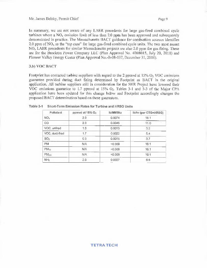
Footprint has contacted turbine suppliers with regard to the 2 ppmvd at 15% 02 VOC emissionsguarantee provided during duct firing determined by Footprint as BACT in the originalapplication. All turbine suppliers still in consideration for the SHR Project have lowered theirVOC emissions guarantee to 1.7 ppmvd at 15% 02. Tables 3-1 and 3-3 of the Major CPAapplication have been updated for this change below and Footprint accordingly changes theproposed BACT determination based on these guarantees.
Table 3-1 Short-Term Emission Rates for Turbine and HRSG Units
Pollutant ppmvd at 151/4 02 lb/MMBtu lb/hr (per CTG+HRSG)
NOx 2.0 0.0074 18.1
CO 2.0 0.0045 11.0
VOC, unfired 1.0 0.0013 3.2
VOC, duct-fired 1.7 0.0022 5.4
SO2 0.3 0.0015 3.7
PM N/A <0.009 16.1
Milo N/A <0.009 16.1
PM2.5 N/A <0.009 16.1
NH3 2.0 0.0027 6.6
TETRATECH
Mr. Jaines Belsky, Permit Chief
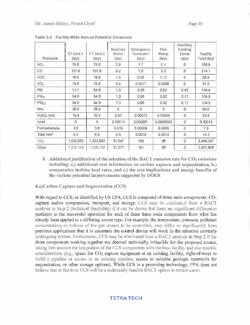
Table 3-3 Facility-Wide Annual Potential Emissions
Page 10
PollutantCT Unit 1(tpy)
CT Unit 2(tpy)
AuxiliaryBoiler(tpy)
EmergencyGenerator
(tpy)
FirePump(tpy)
AuxiliaryCoolingTower(tpy)
FacilityTotal (tpy)
NOx 76.8 76.8 2.9 1.7 0.4 0 158.6
CO 101.8 101.8 9.2 1.0 0.3 0 214.1
VOC 18.6 18.6 1.3 0.35 0.12 0 38.9
502 15.6 15.6 0.4 0.0017 0.0006 0 31.5
PM 54.0 54.0 1.3 0.06 0.02 0.43 109.9
PK() 54.0 54.0 1.3 0.06 0.02 0.43 109.9
P M2.5 54.0 54.0 1.3 0.06 0.02 0.17 109.6
NH3 28.0 28.0 0 0 0 0 56.0
H2SO4 mist 10.4 10.4 0.03 0.00013 0.00005 0 20.8
Lead 0 0 0.00013 0.000001 0.0000003 0 0.00013
Formaldehyde 3.6 3.6 0.019 0.00009 0.0005 0 7.3
Total HAP 6.9 6.9 0.5 0.0018 0.0016 0 14.3
CO2 1,233,952 1,233,952 31,247 180 66 0 2,499,397
CO2e 1,235,142 1,235,142 31,277 181 66 0 2,501,808
4. Additional justification of the selection of the BACT emission rate for CO2 emissionsincluding: a.) additional cost information on carbon capture and sequestration, b.)comparative turbine heat rates, and c.) the cost implications and energy benefits ofthe various potential improvements suggested by DOER
4.a)Carbon Capture and Sequestration (CCS)
With regard to CCS, as identified by US EPA, CCS is composed of three main components: CO2capture and/or compression, transport, and storage. CCS may be eliminated from a BACTanalysis in Step 2 (technical feasibility) if it can be shown that there are significant differencespertinent to the successful operation for each of these three main components from what hasalready been applied to a differing source type. For example, the temperature, pressure, pollutantconcentration, or volume of the gas stream to be controlled, may differ so significantly fromprevious applications that it is uncertain the control device will work in the situation currentlyundergoing review. Furthermore, CCS may be eliminated from a BACT analysis in Step 2 if thethree components working together are deemed technically infeasible for the proposed source,taking into account the integration of the CCS components with the base facility and site-specificconsiderations (e.g., space for CO2 capture equipment at an existing facility, right-of-ways tobuild a pipeline or access to an existing pipeline, access to suitable geologic reservoirs forsequestration, or other storage options). While CCS is a promising technology, EPA does notbelieve that at this time CCS will be a technically feasible BACT option in certain cases.
TETRATECH

Mr. James Belsky, Permit Chief Page 11
As identified by the August 2010 Report of the Interagency Task Force on Carbon Capture andStorage (co-chaired by US EPA and the US Department of Energy), while amine- or ammonia-based CO2 capture technologies are commercially available, they have been implemented eitherin non-combustion applications (i.e., separating CO2 from field natural gas) or in relativelysmall-scale combustion applications (e.g., slip streams from power plants, with volumes on theorder of what would correspond to one megawatt). Scaling up these existing processes representsa significant technical challenge and potential barrier to widespread commercial deployment inthe near term. It is unclear how transferable the experience with natural gas processing is toseparation of power plant flue gases, given the significant differences in the chemical make-up ofthe two gas streams. In addition, integration of these technologies with the power cycle atgenerating plants present •significant cost and operating issues that will need to be addressed tofacility widespread, cost-effective deployment of CO2 capture. Current technologies could beused to capture CO2 from new and existing fossil energy power plants; however, they are notready for widespread implementation primarily because they have not been demonstrated at thescale necessary to establish confidence for power plant applications.
Regarding pipeline transport for CCS, there is no nearby existing CO2 pipeline infrastructure.The nearest CO2 pipelines to Massachusetts are in northern Michigan and southern Mississippi.With regard to storage for CCS, the Interagency Task Force concluded that while there iscurrently estimated to be a large volume of potential storage sites, "to enable widespread, safe,and effective CCS, CO2 storage should continue to be field-demonstrated for a variety ofgeologic reservoir classes" and that "scale-up from a limited number of demonstration projects towidescale commercial deployment may necessitate the consideration of basin-scale factors (e.g.,brine displacement, overlap of pressure fronts, spatial variation in depositional environments,etc.)."
Based on the abovementioned EPA guidance regarding technical feasibility and the conclusionsof the Interagency Task Force for the CO2 capture component alone (let alone a detailedevaluation of the technical feasibility of right-of-ways to build a pipeline or of storage sites),CCS has been determined to not be technically feasible.
CCS would be the most effective option at reducing GHGs, if successfully applied. However, asthe Congressional Budget Office identified in June 2012, the technology is not economicallyviable now.2 For example, the Center for Climate and Energy Solutions (C2ES) has calculatedthat in general, the levelized cost of electricity from a new-build natural gas-fired combinedcycle power plant is $74.70/MWh without CCS and $108.9IMWh with CCS.3 This costdifferential either (a) makes a CCS-equipped plant completely unprofitable to build and operate,or (b) to the extent that costs are passed along, makes the plant unlikely to be dispatched relativeto more economical plants. The International Energy Agency (IEA) has identified the cost-
2Congressional Budget Office, "Federal Efforts to Reduce the Cost of Capturing and Storing Carbon Dioxide,'
Publication No. 4146, June 2012 (available fromhttp://www.cbo.govisites/default/files/cbofiles/attachments/43357-06-28CarbonCapture.pdf), p. 13.3 Center for Climate and Energy Solutions, "Carbon Capture and Storage, October 2012 (available fromhttp://www.c2es.org/technology/factsheet/CCS).
TETRA TECH

Mr. James Belsky, Permit Chief Page 12
effectiveness of applying CCS to natural gas-fired combined-cycle power plants isapproximately $80 per tonne of CO2 avoided.4 On top of that, the C2ES and TEA data are fortypical or average installations, and do not take into account the fact that Massachusetts is aparticularly sub-optimal area for carbon sequestration, being one of the few states identified inthe 2012 North American Carbon Storage Atlas as having zero carbon storage resources.5 Thisdrawback means that costs for implementing CCS in Massachusetts are even higher, and wouldrequire the construction and operation of a large pipeline extending to a state that does havecarbon storage resources, or offshore.
EPA has not identified .a cost-effectiveness threshold, and none of the BACT/LAERdeterminations for GHGs that are in EPA's Clearinghouse identified quantitative cost-effectiveness thresholds either. However, that being said, none of those determinationsconcluded that CCS was cost-effective either. We are aware that several projects have had toconduct BACT analyses for GHGs and that these results are not shown in the Clearinghouse;however, to our knowledge, even in the areas of the U.S. that are more conducive to GHGstorage than Massachusetts, there have been no determinations that CCS is cost-effective fornatural gas-fired combined cycle electric generating plants.
4.b) Comparative Combined Cycle Heat Rates and Proposed GHG BACT
In Section 5.1 of the Plan Approval/PSD Application, we proposed a "new and clean" full loadISO corrected heat rate for each combined cycle unit of 7,080 Btu/kWhr. This is based on HHV,and net output to the grid. Using the EPA Part 75 default CO2 emission factor of 118.9lb/MMBtu, this corresponds to a proposed GHG BACT emission rate of 842 lb/MWhr. This i•salso for "new and clean" conditions, full load, and corrected to ISO conditions. These values arebased on the projected performance of the Siemens SCC6-5000F(5) Flex-PlantTM 30.
If the GE 107FA.05 combined cycle plant is installed, the GE equipment would have a better(lower) heat rate. The projected "new and clean" full load ISO corrected heat rate for each GE-based combined cycle unit would be 6,940 Btu/kWhr. This is also based on HHV, and net outputto the grid. Using the EPA Part 75 default CO2 emission factor of 118.9 lb/MMBtu, thiscorresponds to a proposed GHG BACT emission rate (for GE) of 825 lb/MWhr. This is also for"new and clean" conditions, full load, and corrected to ISO conditions.
The final selection of the SHR project equipment has not been announced. The comparativeefficiency will be a key factor in this selection, along with various other technical andcommercial considerations.
4 Matthias Finkenrath (International Energy Agency), "CO2 Capture Costs", keynote presented at the CCS CostsWorkshop, March 22-23, 2011, Paris (available from http://sequestration.mitedu/pdf/2011%2OCCS%20Cost
%20Workshop%20-%20Proceedings.pdf ).
5 North American Carbon Atlas Partnership (NACAP), "The North American Carbon Storage Atlas 2012" (availablefrom http://www.nethdoe.govnechnologies/carbon searefshelf/NACSA2012.pdf), p. 49.
TETRATECH
Mr. James Belsky, Permit Chief Page 13
4.c) Energy Efficiency Improvements Suggested by DOER
The Massachusetts Department of Energy Resources (DOER), in comments made on the DraftEIR, suggested several energy efficiency improvements in order to reduce the plant parasiticload. The improvements suggested are: high efficiency exterior and industrial interior lighting,variable speed electric drives and motors, piping and valve design to reduce pressure losses, anduse of premium, efficiency transformers.
With respect to exterior and industrial interior lighting, the SHR Project will use high efficiencyLED lighting for these areas. (The Project will also use high efficiency lighting in theAdministration Building and Operations Center as documented in the FEIR). Attachment 2provides a summary of the energy benefits of the high efficiency exterior and industrial interiorlighting compared to standard lighting.
With respect to variable speed electric drives and motors, piping and valve design to reducepressure losses, and use of premium efficiency transformers, engineering evaluation of thesemeasures is still ongoing and the results of these evaluations will be provided in a latersupplement.
5. Additional information on start-up emissions and durations and express allemissions also on an energy output basis (in units of lb/MW-hr)
5.a) Startup Emissions
Table 5-3 of the Plan Approval/PSD Application provides the estimated startup/shutdownemissions performance for each combined cycle unit. This is expressed in pounds of emissionsover 45 minutes for startup and for 30 minutes for shutdown.. This is estimated performance forthe project which we fully expect will be met by the installed equipment. However, since varioussite-specific equipment factors can influence the actual startup/shutdown emissions, Footprint isrequesting that the limits in Table 5-3 be considered as "provisional" limits for the first year ofcommercial operation. Then, after review of the stack test data and CEMS data for the first yearof operation, final startup/shutdown limits will be established. The Pioneer Valley Energy CenterPlan Approval contains a provision to this effect (page 35 of 54, Table I I, footnote 3.
5.b) Proposed Emission Limits — Energy Output Basis
Proposed emission limits on an energy output basis are provided in Table 2 below. Theseproposed limits are based on the proposed heat rate for the Siemens turbine (7,080 Btu/kWhrnet), since this will provide proposed limits inclusive of both the Siemens and GE equipment.These limits are proposed to apply to full load operation, "new and clean," to be demonstrated byan initial stack test, with the turbine heat rate corrected to ISO conditions.
TETRA TECH

Mr. James Belsky, Permit Chief Page 14
Table 2 Short-Term Emission Rates for Turbine and HRSG Units — Energy Output Basis
Pollutant
pounds/MWhrcorrected to ISO
conditions
NO,, 0.052
CO 0.032
VOC, unfired 0.009
VOC, duct-tired 0.016
SO2 0.011
PM 0.064
PMic, 0.064
FM25 0.064
NH3 0.019
6. A more robust determination in accordance with the condition specified in 310CMR 7.00: Appendix A that "by means of an analysis for alternative sites, sizes,production processes, and environmental control techniques" the Proponent shalldemonstrate that "the benefits of the proposed source significantly outweigh theenvironmental and social costs imposed as a result of its location, construction, ormodification."
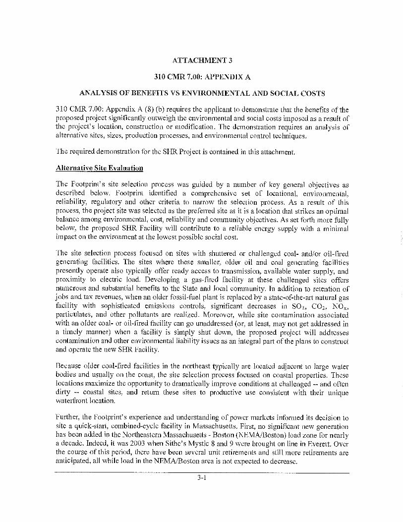
Attachment 3 provides the requested Appendix A demonstration.
7. An update on the status of obtaining the required emissions offsets
To date, Footprint has secured 194 tons per year (tpy) of the required 200 tpy of emissionsoffsets. As recorded in the latest Massachusetts ERC Registry dated February 13, 2013, 59 tpywere purchased from the Newark Group on February 4, 2013 (22 tpy from a shutdown atHaverhill Paperboard and 37 tpy from a shutdown at Natick Paperboard). Footprint has enteredinto a contract to purchase another 135 tpy from a prior source shutdown in Rhode Island and thetransfer is expected to be recorded in the ERC Registry soon. The remaining 6 tpy will besecured before the air permit is finalized.
8. Final air quality impact modeling based on the plant with the selected turbinevendor and final site configuration and including GE Lynn and WheelabratorSaugus as interacting sources for PM and NO7, and Rousselot, Peabody MunicipalLight, and Marblehead Municipal Light as interacting sources for 1-hour NO),
This final air dispersion modeling will be provided in a second supplement to the applicationexpected to be submitted in late May.
TETRATECH

Mr. James Belsky, Permit Chief Page 15
9. A more detailed analysis of federal environmental justice (EJ) considerations insupport of the PSD application
The expanded EJ analysis is dependent on final air dispersion modeling results so it will beincluded with the second supplement.
10. Documentation of the notifications provided to other federal agencies and the tribalcouncils as stipulated in the delegation agreement for the PSD Program betweenMassDEP and EPA Region 1
Footprint wanted this supplement and the original December 21, 2012 application to both beavailable to the other federal agencies and the tribal councils so we will be copying you directlyon the notification letters to these organizations which will be sent within 5 days.
11. An updated assessment of background noise levels including a review of otherrecent sound measurement data that have been collected in the vicinity of the studyarea
The background noise levels used in our operational noise impact assessment have been updated.The two changes made are as follows:
• Nighttime ambient levels that were measured by Tetra Tech before midnight have beenconservatively reduced by 2 dBA for purposes of the impact assessment. We stillconsider the nighttime measurements made between 10 PM and midnight to representvalid data. However, in order to ensure the impact analysis is conservative, the 2 dBAsubtraction has been made for ST-1, ST-2, ST-5, ST-6, and ST-8.
• The second change is that two new monitoring locations are added, Winter Island WindTurbine (WIWT-1 or R-1) and WIWT-2 or R-2. This is additional data in the publicrecord indicating lower nighttime ambient levels than the other data at one of thelocations. The locations for R-1 and R-2 are provided in Attachment 4.
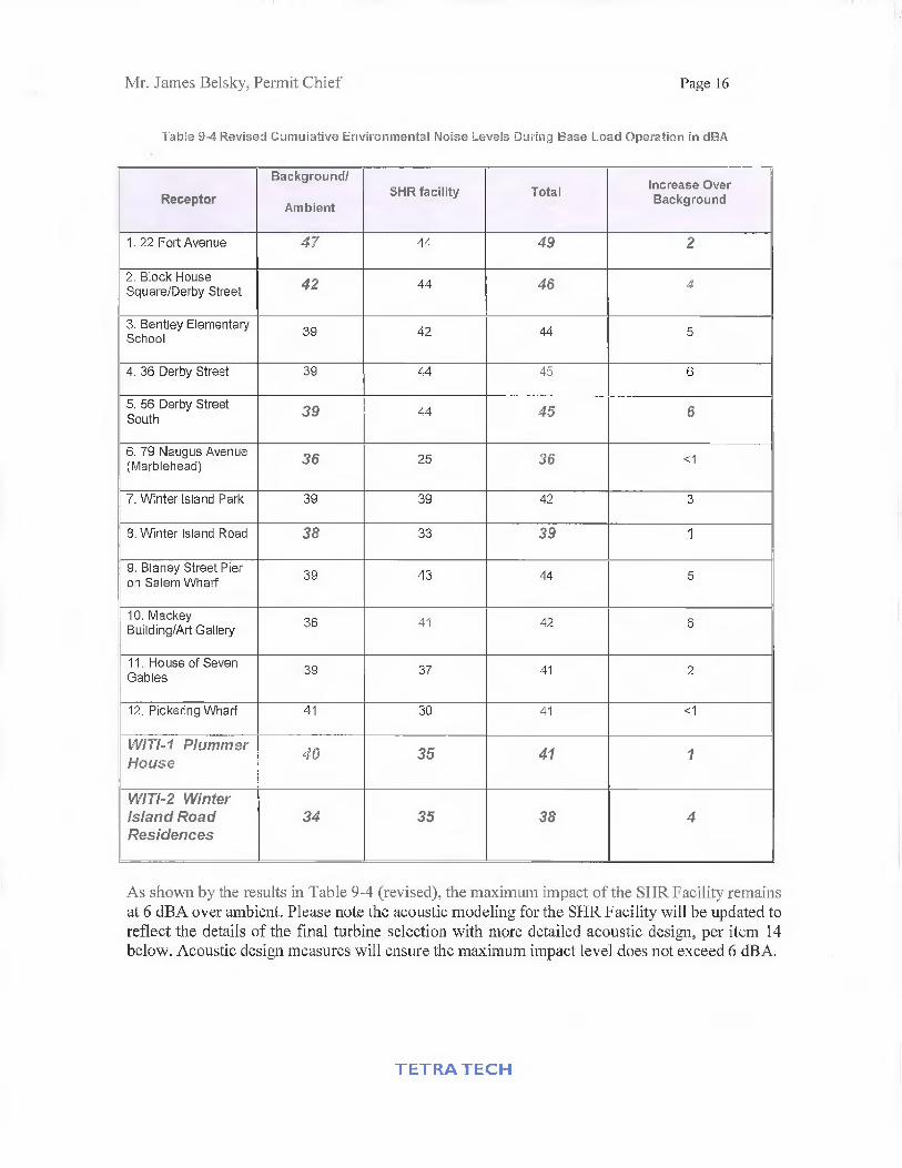
Table 9-4 from the PSD/Plan Application is updated for these changes. New and revised valuesare in bold and italics.
TETRATECH
Mr. James Belsky, Permit Chief Page 16
Table 9-4 Revised Cumulative Environmental Noise Levels During Base Load Operation in dBA
Receptor
Background/
AmbientSHR facility Total increase Over
Background
1. 22 Fort Avenue 47 44 49 2
2. Block HouseSquare/Derby Street 42 44 46 4
3. Bentley ElementarySchool
39 42 44 5
4. 36 Derby Street 39 44 45 6
5. 56 Derby StreetSouth 39 44 45 6
6. 79 Naugus Avenue(Marblehead) 36 25 36 <1
7. Winter island Park 39 39 42 3
8. Winter Island Road 38 33 39 1
9. Blaney Street Pieron Salem Wharf
39 43 44 5
10. MackeyBuilding/Art Gallery
36 41 42 6
11. House of SevenGables
39 37 41 2
12. Pickering Wharf 41 30 41 <1
W177-1 PlummerHouse
40 35 41 1
WITI-2 Winterisland RoadResidences
34 35 38 4
As shown by the results in Table 9-4 (revised), the maximum impact of the SHR Facility remainsat 6 dBA over ambient. Please note the acoustic modeling for the SHR Facility will be updated toreflect the details of the final turbine selection with more detailed acoustic design, per item 14below. Acoustic design measures will ensure the maximum impact level does not exceed 6 dBA.
TETRA TECH

Mr. James Belsky, Permit Chief Page 17
12. A more detailed assessment of construction noise impacts and potential mitigationtechniques
Acoustic emission levels for activities associated with the construction of the SHR Facility have
been updated to reflect potential maximum impacts for construction activity occurring close to
the edge of the site, and to reflect the potential reduction in offsite impacts via use of a temporary
construction noise barrier. Basic construction noise estimates remain based upon typical ranges
of energy equivalent noise levels at construction sites, as documented by the U.S. Environmental
Protection Agency (EPA) (U.S. EPA, Technical Document NTID300.1, December 1971).
Construction noise is highly variable because most construction equipment operates
intermittently, and the types of construction equipment change with construction phase. The EPA
methodology distinguishes between type of construction and construction phase.
Using those energy equivalent noise levels as input to a basic propagation model, construction
noise levels were recalculated at the closest residential locations and at the Bentley Elementary
School. The basic model assumed spherical wave divergence and now also reflects worse case
location of equipment for a given construction phase. Furthermore, the model conservatively
assumes that all pieces of construction equipment associated with an activity would operate
simultaneously for the duration of that activity to estimate the average noise levels from the
construction equipment over the duration of phase. Atmospheric absorption and terrain effects,
including the shielding effects of the berm which would be constructed during Phase 1, have
been conservatively ignored. An additional level of conservatism was built into the construction
noise model by excluding the shielding effects due to intervening structures and buildings along
the propagation path from the site to noise-sensitive locations in the community.
The results of these calculations are provided in Table 3 and show construction sound levels at
the closest residential locations on Derby Street would in most instances be between 65 and 83
dBA.
TETRA TECH

Mr. James Belsky, Permit Chief Page 18
Table 3: Equivalent Noise Levels by Construction Phase at Closest Noise Sensitive Areas
Construction Phase
EPA
Construction
Noise Level
50 ft
Closest
Residences
Bentley
Elementary
School
Bentley
Elementary
Fields
Leg, (dBA)
Ground clearing
(Phase 1)84 78 63 71
Excavation
(Phase 1)89 83 68 76
Foundations and concrete
pouring(Phase 2)
78 65 56 62
Steel erection
(Phase 3)72 63 69
Mechanical
(Phase 4)81 68 59 65
Finishing Work
(Phase 5)89 83 68 76
Temporary Construction Noise Barrier
A review of the effectiveness of a temporary property line noise barrier was completed. A
temporary sound wall is a sound barrier that is a non-retractable temporary wall that is typically
constructed of 3/4 inch Medium Density Overlay (MD) plywood, or other material of equivalent
utility and appearance having a surface weight of 2 pounds per square foot or greater. The
analysis assumed a Sound Transmission Class of STC 30, or greater, per American Society for
Testing and Materials (ASTM) Test Method E90 and on one side with glass fiber, mineral wool,
or other similar type noise-absorbing material at least 2-inches thick and have a Noise Reduction
Coefficient rating of NRC-0.85, or greater, as per ASTM Test Method C423. The materials used
for temporary barriers should be sufficient to last through the duration of the construction work,
and maintained in good repair. The barriers will be installed such that sound-absorptive surfaces
TETRA TECH

Mr. James Belsky, Permit Chief Page 19
face the site. When .the barrier units are joined together, the mating surfaces of the barrier sides
are flush with each other and gaps between barrier units and between the bottom edges of the
barrier panels and the ground would be closed with material of sufficient density to attenuate
sound. The acoustic modeling assumed a barrier height of 12 feet and placement is along the
property line adjacent to Derby Street. The results of the estimated barrier insertion loss
calculations and received noise levels at key receptor locations are presented in Table 4. The
mitigated construction sound levels at the closest residential locations on Derby Street would in
most instances be between 54 and 72 dBA.
Table 4: Equivalent Noise Levels by Construction Phase at Closest Noise Sensitive Areas with
Temporary Noise Barrier
Construction Phase
EPA
Construction
Noise Level
50 ft
Closest
ResidencesBentley
Elementary
School
Bentley
Elementary
Fields
1,,, (dBA)
Ground clearing
(Phase 1)84 67 51 59
Excavation
(Phase 1)89 72 56 64
Foundations and concrete
pouring
(Phase 2)
7' 44 50
Steel erection
(Phase 3)85 i :: 1 57
Mechanical(Phase 4)
81
Finishing Work
(Phase 5)89 72 64
13. Noise specifications for key plant equipment
These specifications are provided in Attachment 5.
TETRA TECH

Mr. James Belsky, Permit Chief Page 20
14. Final acoustic modeling for the facility based on the turbine vendor selected, and thefinal site layout and noise mitigation plan
Final acoustic modeling will be included with the second supplement in late May.
15. Vendor acoustic data for key plant equipment used in the final acoustic modeling
Vendor acoustic data will be included with the second supplement.
16. A more robust analysis of the costs and benefits of alternative noise mitigationtechniques
The requested analysis of alternative noise mitigation techniques will be included with thesecond supplement.
If you have any questions, please contact either me at (617) 803-7809 or George Lipka at (617)443-7568.
Sincerely,
Keith H. KennedySenior Consultant — Energy Programs
Attachments
TETRA TECH

First Supplement to Major Comprehensive Plan Application —Salem Harbor Redevelopment (SHR) Project (Transmittal Number X254064)
Attachment 1
EPA RBLC Clearinghouse for NO,

Attachment 1 - EPA RBLC Clearinghouse
Lowest NOx Emission Rates for Category 15.210
RBLC IDPermit Issuance
DateCorporate & Facility Name
Standard EmissionLimit (NOx)
CT-0151 02/25/2008
05/14/2004
06/23/2005
01/19/2007
KLEEN ENERGY SYSTEMS, LLC
SEMPRA ENERGY RESOURCESCOPPER MOUNTAIN POWEREMPIRE GENERATING CO. LLCEMPIRE POWER PLANTNEW ATHENS GENERATING CO. LLC
2.0000 PPM @ 15%
NV-003702
2.0000 PPM 15%
NY-010002
2.0000 PPMVD AT
NY-009815% 02
2.0000 PPMVDATHENS GENERATING PLANT 15% 02
AZ-0049 09/04/2003 ALLEGHENY ENERGY SUPPLY LLC 2.0000 PPM @ 15LA PAZ GENERATING FACILITY 02
AZ-0047 12/01/2004 DOME VALLEY ENERGY PARTNERS 2.0000 PPM 15%WELLTON MOHAWK GENERATING 02STATION
AZ-0047 12/01/2004 DOME VALLEY ENERGY PARTNERS 2.0000 PPM AT 15%WELLTON MOHAWK GENERATING 02STATION
FL-0263 02/08/2005 FLORIDA POWER AND LIGHT 2.0000 PPM a 15 %FPL TURKEY POINT POWER PLANT 02
NV-0035 08/16/2005 SIERRA PACIFIC POWER COMPANY 2.0000 PPM 15%TRACY SUBSTATION EXPANSION 02PROJECT
NV-0035 08/16/2005 SIERRA PACIFIC POWER COMPANY 2.0000 PPM (@ 15%TRACY SUBSTATION EXPANSION 02PROJECT
NV-0038 12/29/2003 IVANPAH ENERGY CENTER, L.P. 2.0000 PPIVI(@, 15%IVANPAH ENERGY CENTER, L.P. 02
WA-0315 04/17/2003 SUMAS ENERGY 2 GENERATION 2.0000 PPM @ 15%FACILITY 02SUMAS ENERGY 2 GENERATIONFACILITY
AZ-0043 11/12/2003 DUKE ENERGY ARLINGTON VALLEY 2.0000 PPM 15%DUKE ENERGY ARLINGTON VALLEY 02(AVEFII)
AZ-0043 11/12/2003 DUKE ENERGY ARLINGTON VALLEY 2.0000 PPM A 15%DUKE ENERGY ARLINGTON VALLEY 02(AVEFII)
CA-1097 05/27/2003 MAGNOLIA POWER PROJECT, SCPPA 2.0000 PPM A 15%MAGNOLIA POWER PROJECT, SCPPA 02
CA-1096 05/27/2003 VERNON CITY LIGHT & POWER 2.0000 PPM a 15%VERNON CITY LIGHT & POWER 02
AZ-0039 03/07/2003 SALT RIVER PROJECT/SANTAN GEN. 2.0000 PPM @ 15%PLANT 02SALT RIVER PROJECT/SANTAN GEN.PLANT
CA-0997 09/01/2003 SACRAMENTO MUNICIPAL UTILITY 2.0000 PPM 15%DISTRICT 02
UT-0066 05/17/2004 PACIFICORP 2.2500 PPM @ 15%CURRANT CREEK 02
WY-0061 04/04/2003 BLACK HILLS CORP. 2.5000 PPM @ 15%NEIL SIMPSON TWO 02
FL-0244 04/16/2003 FLORIDA POWER & LIGHT 2.5000 PPM (@, 15%FPL MARTIN PLANT 02
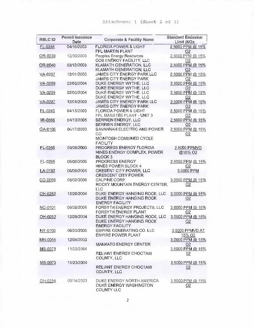
Attachment 1 (Sheet 2 of 3)
RBLC IDPermit Issuance
DateCorporate & Facility Name
Standard EmissionLimit (NOx
FL-0244 04/16/2003 FLORIDA POWER & LIGHT 2.5000 PPM(a 15%FPL MARTIN PLANT 02
OR-0039 12/30/2003 Peoples Energy Resources 2.5000 PPM 15%COB ENERGY FACILITY, LLC 02
OR-0040 03/12/2003 KLAMATH GENERATION, LLC 2.5000 PPM (a 15%KLAMATH GENERATION, LLC 02
VA-0287 12/01/2003 JAMES CITY ENERGY PARK LLC 2.5000 PPM(a 15%JAMES CITY ENERGY PARK 02
VA-0289 02/05/2004 DUKE ENERGY WYTHE, LLC 2.5000 PPM a 15%DUKE ENERGY WYTHE, LLC 02
VA-0289 02/05/2004 DUKE ENERGY WYTHE, LLC 2.5000 PPM (@ 15%DUKE ENERGY WYTHE, LLC 02
VA-0287 12/01/2003 JAMES CITY ENERGY PARK LLC 2.5000 PPM (a7 15%JAMES CITY ENERGY PARK 02
FL-0245 04/15/2003 FLORIDA POWER & LIGHT 2.5000 PPM (a 15%FPL MANATEE PLANT - UNIT 3 02
Ml-0366 04/13/2005 BERRIEN ENERGY, LLC 2.5000 PPM (a, 15%BERRIEN ENERGY, LLC 02
GA-0105 04/17/2003 SAVANNAH ELECTRIC AND POWER 2.5000 PPM A 15%CO 02MCINTOSH COMBINED CYCLEFACILITY
FL-0256 09/08/2003 PROGRESS ENERGY FLORIDA 2.5000 PPMVDHINES ENERGY COMPLEX, POWER @15% 02BLOCK 3
FL-0265 06/08/2005 PROGRESS ENERGY 2.5000 PPM (a 15%HINES POWER BLOCK 4 02
LA-0192 06/06/2005 CRESENT CITY POWER, LLC 3.0000 PPMCRESCENT CITY POWER
CO-0056 05/02/2006 CALPINE CORP. 3.0000 PPM (a 15%ROCKY MOUNTAIN ENERGY CENTER 02LLC
OH-0252 12/28/2004 DUKE ENERGY HANGING ROCK, LLC 3.0000 PPM(a. 15%DUKE ENERGY HANGING ROCK 02ENERGY FACILITY
NC-0101 09/29/2005 FORSYTH ENERGY PROJECTS, LLC 3.0000 PPM(a, 15%FORSYTH ENERGY PLANT 02
OH-0252 12/28/2004 DUKE ENERGY HANGING ROCK, LLC 3,0000 PPM A 15%DUKE ENERGY HANGING ROCK 02ENERGY FACILITY
NY-0100 06/23/2005 EMPIRE GENERATING CO. LLC 3.0000 PPMVD ATEMPIRE POWER PLANT 15% 02
MN-0054 12/04/2003 3.0000 PPM er 15%MANKATO ENERGY CENTER 02
MS-0073 11/23/2004 3.5000 PPM (a 15%RELIANT ENERGY CHOCTAW 02COUNTY, LLC
MS-0073 11/23/2004 3.5000 PPM a 15%RELIANT ENERGY CHOCTAW 02COUNTY, LLC
OH-0254 08/14/2003 DUKE ENERGY NORTH AMERICA 3.5000 PPM (a, 15%DUKE ENERGY WASHINGTON 02COUNTY LLC
2
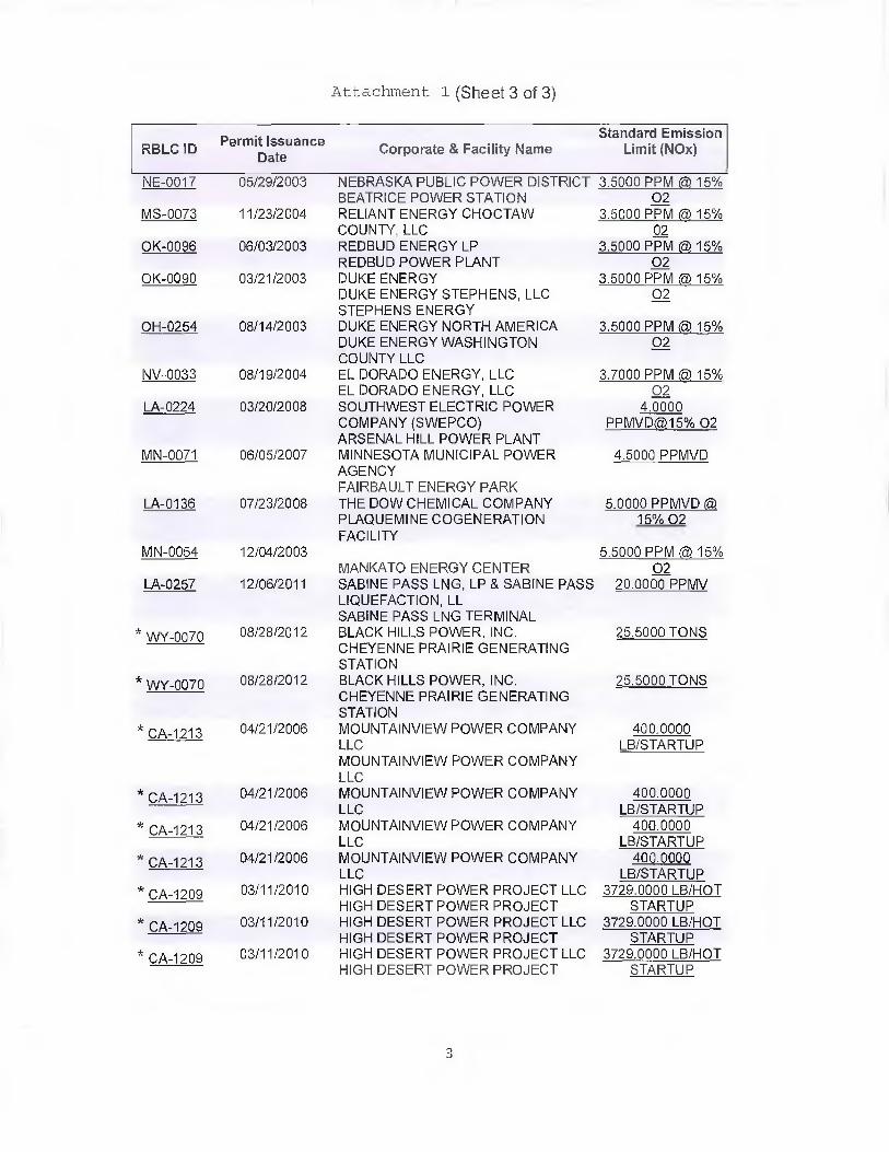
Attachment 1 (Sheet 3 of 3)
RBLC IDPermit Issuance
DateCorporate & Facility Name
Standard EmissionLimit (140x)
NE-0017 05/29/2003 NEBRASKA PUBLIC POWER DISTRICT 3.5000 PPM A 15%BEATRICE POWER STATION 02
MS-0073 11/23/2004 RELIANT ENERGY CHOCTAW 3.5000 PPM @ 15%COUNTY, LLC 02
OK-0096 06/03/2003 REDBUD ENERGY LP 3.5000 PPM a, 15%REDBUD POWER PLANT 02
OK-0090 03/21/2003 DUKE ENERGY 3.5000 PPM 15%DUKE ENERGY STEPHENS, LLC 02STEPHENS ENERGY
OH-0254 08/14/2003 DUKE ENERGY NORTH AMERICA 3.5000 PPM (&. 15%DUKE ENERGY WASHINGTON 02COUNTY LLC
NV-0033 08/19/2004 EL DORADO ENERGY, LLC 3.7000 PPM @ 15%EL DORADO ENERGY, LLC 02
LA-0224 03/20/2008 SOUTHWEST ELECTRIC POWER 4.0000COMPANY (SWEPCO) PPMVD(@.15% 02ARSENAL HILL POWER PLANT
MN-0071 06/05/2007 MINNESOTA MUNICIPAL POWER 4.5000 PPMVDAGENCYFAIRBAULT ENERGY PARK
LA-0136 07/23/2008 THE DOW CHEMICAL COMPANY 5.0000 PPMVDPLAQUEMINE COGENERATION 15% 02FACILITY
MN-0054 12/04/2003 5.5000 PPM (" 15%MANKATO ENERGY CENTER 02
LA-0257 12/06/2011 SABINE PASS LNG, LP & SABINE PASS 20.0000 PPMVLIQUEFACTION, LLSABINE PASS LNG TERMINAL
* WY-0070 08/28/2012 BLACK HILLS POWER, INC. 25.5000 TONSCHEYENNE PRAIRIE GENERATINGSTATION
* WY-0070 08/28/2012 BLACK HILLS POWER, INC. 25.5000 TONSCHEYENNE PRAIRIE GENERATINGSTATION
* CA-1213 04/21/2006 MOUNTAINVIEW POWER COMPANY 400.0000LLC LB/STARTUPMOUNTAINVIEW POWER COMPANYLLC
* CA-1213 04/21/2006 MOUNTAINVIEW POWER COMPANY 400.0000LLC LB/STARTUP
* CA-1213 04/21/2006 MOUNTAINVIEW POWER COMPANY 400.0000LLC LB/STARTUP
* CA-1213 04/21/2006 MOUNTAINVIEW POWER COMPANY 400.0000LLC LB/STARTUP
* CA-1209 03/11/2010 HIGH DESERT POWER PROJECT LLC 3729.0000 LB/HOTHIGH DESERT POWER PROJECT STARTUP
* CA-1209 03/11/2010 HIGH DESERT POWER PROJECT LLC 3729.0000 LB/HOTHIGH DESERT POWER PROJECT STARTUP
* CA-1209 03/11/201G HIGH DESERT POWER PROJECT LLC 3729.0000 LB/HOTHIGH DESERT POWER PROJECT STARTUP
3

First Supplement to Major Comprehensive Plan Application —Salem Harbor Redevelopment (SHR) Project (Transmittal Number X254064)
Attachment 2
Lighting Energy Savings and Avoided CO2 Emissions for High Efficiency
Lighting Operation Comparison - Standard vs. LED

Attachment 2 (Sheet 1 of 2)
FOOTPRINT — SALEM HARBOR
LIGHTING OPERATION COMPARISON STANDARD VS LED
INTERIOR (Illuminated 24/7/365)
Fixture Type B Standard
Std (HPS) = Holophane Type P3M-150-HP-P-GB-MT-FDZ-PD-PS Watts / Fixture=170 x 258 Fixtures = 43860 Watts
LED = Holophane Type PLED-98-35-5K-27-PD-NA-W-L5H-55C Watts / Fixture=113.9 x 258 Fixtures =
Fixture Type F3
Std(Fluor)= Lithonia Type IBZ 432L WDU PCL125
LED = Clean Light Green Light Type 4P1288NW
Total Wattage Consumed =
SAVINGS =
EXTERIOR (Illuminated 12/7/365)
LED
29386.2 Watts
Watts / Fixture= 151 x 83 Fixtures = 12553 Watts
Watts / Fixture= 66.2 x 83 Fixtures = 5494.6 Watts
56393 Watts vs 34880.8 Watts
38% *
Fixture Type A
Std (HPS) =Luminis Wall Mtd Type W670-ED17-277-DGT-PH-ACW-R4 Watts / Fixture=170 x 20 Fixtures =
LED = Luminis Wall Mounted Type MA14-L21W48-LD55 Watts / Fixture=47,05 x 20 Fixtures =
Fixture Type B
Std (HPS =Holophane Wallpack Type W4100HP-VT-SKB
LED = Maxlight Wallpack Type MLLWP6OLED50
3400 Watts941.0 Watts
445.9 Watts
Fixture Type C
Std (HPS)=GE M250A2 Roadway Type M2AC-25-S1N2G-MC3-1F Watts / Fixture= 275 x 73 Fixtures= 20075 Watts
LED = GE Evolve Roadway Type ERMC*B660A**** Watts / Fixture= 127 x 73 Fixtures = 9271 Watts
Fixture Type D
Std (HPS) = Spaulding Cimarron Type CR1-WB-S15-H5-F-T-BL-PR4 Watts / Fixture= 330 x 64 Fixtures = 21120 Watts
LED = Spaulding Cimarron Type SW CL1-90L-4K-SW-105-N2 Watts / Fixture= 330 x 64 Fixtures = 21120 Watts
Watts / Fixture=110 x 7 Fixtures = 770 Watts
Watts / Fixture= 63.7 x 7 Fixtures =
Total Wattage Consumed = 45365 Watts vs 31777.9 Watts
SAVINGS = 30%
*Savings indicated are operational energy savings only and do not include maintenance and lamp replacement cost savings.

Attachment 2 (Sheet 2 of 2)Energy Savings and Avoided CO2 Emissions for High Efficiency Lighting
Standard
Lighting (watts)
LED High Efficiency
Lighting (watts)
Energy
Savings
(watts)
Energy Savings
(MWhrs/year)
industrial Interior Lighting Energy
Savings56,393 34,881 21,512 188.4
Exterior Lighting Energy Savings 45,365 31,778 13,587 59.5
Total Energy Savings 35,099 248.0
Avoided CO2 Emissions = (248 MWhrs/year)(825 lbs/MWhr)/(2000 lbs/ton) = 102.3
tons CO2/year
Notes:
1. For annual energy savings, the interior industrial lighting is assumed to operate for 24 hours per day, 365 days per year.
2. For annual energy savings, the exterior lighting is assumed to operate for 12 hours per day, 365 days per year.
3. Avoided CO2 emissions are conservatively based on the proposed CO2BACT rate for the CCG combined cycle units of
825 lb/MWhr. The actual avoided CO2 emissions due to the delivery of 248 additional MWhrs to the grid will be
greater than 102.3 tons per year. 1 Il
First Supplement to Major• Comprehensive Plan Application —Salem Harbor Redevelopment (SHR) Project (Transmittal Number X254064)
Attachment 3
310 CMR 7.00: APPENDIX A
Analysis of Benefits vs Environmental and Social Costs
ATTACHMENT 3
310 CMR 7.00: APPENDIX A
ANALYSIS OF BENEFITS VS ENVIRONMENTAL AND SOCIAL COSTS
310 CMR 7.00: Appendix A (8) (b) requires the applicant to demonstrate that the benefits of theproposed project significantly outweigh the environmental and social costs imposed as a result ofthe project's location, construction or modification. The demonstration requires an analysis ofalternative sites, sizes, production processes, and environmental control techniques.
The required demonstration for the SHR Project is contained in this attachment.
Alternative Site Evaluation
The Footprint's site selection process was guided by a number of key general objectives asdescribed below. Footprint identified a comprehensive set of locational, environmental,reliability, regulatory and other criteria to narrow the selection process. As a result of thisprocess, the project site was selected as the preferred site as it is a location that strikes an optimalbalance among environmental, cost, reliability and community objectives. As set forth more fullybelow, the proposed SHR Facility will contribute to a reliable energy supply with a minimalimpact on the environment at the lowest possible social cost.
The site selection process focused on sites with shuttered or challenged coal- and/or oil-firedgenerating facilities. The sites where these smaller, older oil and coal generating facilitiespresently operate also typically offer ready access to transmission, available water supply, andproximity to electric load. Developing a gas-fired facility at these challenged sites offersnumerous and substantial benefits to the State and local community. In addition to retention ofjobs and tax revenues, when an older fossil-fuel plant is replaced by a state-of-the-art natural gasfacility with sophisticated emissions controls, significant decreases in S02, CO2, NOx,particulates, and other pollutants are realized. Moreover, while site contamination associatedwith an older coal- or oil-fired facility can go unaddressed (or, at least, may not get addressed ina timely manner) when a facility is simply shut down, the proposed project will addressescontamination and other environmental liability issues as an integral part of the plans to constructand operate the new SHR Facility.
Because older coal-fired facilities in the northeast typically are located adjacent to large waterbodies and usually on the coast, the site selection process focused on coastal properties. Theselocations maximize the opportunity to dramatically improve conditions at challenged -- and oftendirty -- coastal sites, and return these sites to productive use consistent with their uniquewaterfront location.
Further, the Footprint's experience and understanding of power markets informed its decision tosite a quick-start, combined-cycle facility in Massachusetts. First, no significant new generationhas been added in the Northeastern Massachusetts - Boston (NEMA/Boston) load zone for nearlya decade. Indeed, it was 2003 when Sithe's Mystic 8 and 9 were brought on line in Everett. Overthe course of this period, there have been several unit retirements and still more retirements areanticipated, all while load in the NEMA/Boston area is not expected to decrease.
3-1

The site selection process was in large part predicated on Footprint's ability to develop a specifictype of facility -- one that can bring on line up to 300 MW of its output within 10 minutes,Indeed, the SHR Facility will be extremely valuable to ISO-NE from the perspectives ofreliability, cost and reducing emissions, as it enables ISO-NE to respond quickly and efficientlyin emergency and other situations while reducing its reliance on spinning reserves, which areexpensive and polluting.
Finally, the Footprint recognizes that the SHR Facility is particularly well-suited forMassachusetts because the proposed technology facilitates and supports the development of windgeneration -- a renewable resource strongly favored in the Commonwealth. Because wind poweris an intermittent resource, it is especially important for the region to be able to rely on clean andcost-effective quick-start generation during those periods when wind output is not available. TheSHR Facility's quick-start technology will be less expensive and less polluting than spinningreserves and peaker units which presently filI the gap when wind is unavailable. Accordingly, theSHR Facility will be an extremely valuable addition to the State's and region's resourceportfolio .1
Site Selection Characteristics
In addition to the general objectives discussed above, Footprint identified a number of locational,environmental, and community considerations for purposes of identifying and analyzingalternative sites.
Locational Considerations
• Sufficient acreage - Footprint analyzed only those sites with a minimum of 20 acresavailable for the proposed facility and ancillary structures;
• Proximity to electric load;• Availability of natural gas - Footprint analyzed those sites where a gas
interconnection was 5 miles or less from the proposed site; where sufficient capacitywas available; and where any pipeline-related construction could be completedconsistent with the schedule for constructing the proposed power facility;
• Availability of electrical interconnection;• Compatibility with local zoning and surrounding uses;• Limited number of sensitive receptors in close proximity to project Site;• Expected ease of permitting; and• Local support for an electric generating facility in the municipality.
1 In a report issued by ISO-NE on December 5, 2010, ISO-NE's consultant reported that overall Total OperatingReserve — representing the sum of Ten-Minute Spinning Reserves and Ten-Minute Non-Spinning reserves wouldincrease by 500 MW to 600 MW in a 20% wind penetration scenario (see pages 21-22). The Ten-Minute Non-Spinning Reserve function of the SHR Facility provided by its quick-start capabilities are far preferable from a costand emissions stand-point than Ten-Minute Spinning Reserves provided by less efficient, less flexible units.(http://www.iso-ne.comicommittees/cornm wkgrps/prtcpnts comm/packeports/2010/newis es.pdf)
3-2
Environmental Considerations
• Ability to reduce current air quality impacts consistent with federal/staterequirements;
• Potential to return coastal properties to productive use consistent with Staterequirements and objectives;
• Ability to minimize water consumption;• Ability to minimize wastewater impacts;• Ability to minimize wetlands impacts;• Ability to minimize noise impacts;• Ability to minimize land use impacts consistent with local zoning requirements;• Ability to minimize historical, archaeological and cultural impacts consistent with
federal and state requirements;• Ability to minimize visual impacts;• Ability to minimize traffic impacts;• Ability to minimize solid and hazardous waste impacts;• Ability to ensure safe transportation and storage of ammonia and other materials; and• Minimization of electric and magnetic field effects.
Community Considerations
Footprint employed the following community-related considerations as part of its process ofnarrowing its list of identified sites:
▪ Support from municipal officials;• Importance of continuing tax revenues;• Importance of continuing project-related jobs; and• Support from neighbors.
Benefits of the Salem Site
The Salem site presents a significant number of attributes that satisfy Footprint's locational,environmental and community criteria set forth, above. For example:
• The Salem Harbor Station facility was considered to be one of the "Filthy Five" electricgeneration plants in Massachusetts, with a long history of environmental challenges.Indeed, construction of the SHR Facility on the landward portion of the site will affordFootprint the opportunity to clean up the portion of the site currently occupied by thesoon—to—be shuttered Salem Harbor Station, and return that valuable waterfront land toproductive use, consistent with State law. Having entered commercial operation as agenerating facility in 1951, the Salem Harbor Site has a long history as a site forelectricity generation.
• The Salem Harbor Station has been required by ISO-NE to operate for reliabilitypurposes through May 2014, offering Footprint the unique opportunity to minimize anygaps in electricity generation beyond that date through the development and permitting ofthe new state-of-the-art SHR Facility,
• The site is close (less than two miles) to natural gas pipeline facilities, namely theinterconnection of the Maritime and Northeast and HubLine pipelines.
3 -3

• There is strong local support for the continuation of electricity generation on the site as ameans of maximizing tax revenues and local employment. The Mayor, other cityofficials, and state senators and representatives, have been vocal supporters of some kindof continued presence of electricity generation at the Site generally and of this Project inparticular.
• There is State support for potential reuse of the Site as demonstrated by (1) the 2011decision to use RGGI funds to supplement the City of Salem's tax revenues for an eight-year period, (2) funding of the Salem Site Reuse Study by the Massachusetts CleanEnergy Center, and (3) the enactment of Chapter 209 of the Acts of 2012 andestablishment of the Salern Harbor Power Station Plan Revitalization Task Force.
• Permitting of the Project is expected given city and state support of the powergeneration/site reuse concept, as well as compatibility of the Project with local zoningrequirements.
• The site is located in close proximity to the electric grid (National Grid system).• The 65-acre Site is sufficiently large to accommodate the SHR Facility and enable further
redevelopment opportunities.• The site offers Footprint the opportunity to significantly reduce air, water supply,
wastewater, noise, visual, and other impacts relative to the current Salem Harbor Facility.• The absence of new generation in Northeastern Massachusetts - Boston (NEMA/Boston)
load zone. Indeed, it has been nearly a decade since any significant new generation,Mystic 8 and 9, has been added in NE1VIA. Over the course of these last ten years, therehave been several unit retirements and still more retirements are anticipated, all whileload in the NEMA/Boston area is not expected to decrease.
• In fiscal year 2010, Dominion paid the City approximately $4.75 million in taxes, makingthe power station the largest taxpayer in Salem. The $4.75 million included a negotiatedusage fee of $1.75 million, and property taxes of $3 million, which included $800,000attributable to the land. Pursuant to G.L. c. 21A, § 22, for an eight -year period, the Citywill be reimbursed the difference between the $4.75 million of tax revenues collectedfrom Dominion in fiscal year 2010 and the reduced tax revenues associated with a full orpartially decommissioned Salem Harbor facility with proceeds from the RGGI AuctionTrust Fund. St. 2011, c. 68, § 33. The economic impact on the City of Salem will besubstantial if a new generating facility is not in place when that eight-year period expires.The proposed SHR Project ensures that the City of Salem will continue to receivesignificant tax revenues associated with the generation of electricity. In addition, bringingthe SHR Facility on line in 2016 would permit dollars from the RGGI Account TrustFund to be redirected away from Salem and to other environmentally beneficial uses.
• The construction of a new power plant, along with demolition of the existing facility andattendant remediation of the site, will bring a significant number of jobs over the courseof the next several years. Footprint expects that approximately 30-40 permanentemployees will be needed to operate the SHR Facility, assuring that operations-relatedemployment at the Salem Harbor site will continue beyond the June 1, 2014 retirementdate of the existing facility.
• The demolition of the existing facility and remediation of the site will enable future useof the remainder of the Site for a variety of marine industrial purposes, thereby providingopportunities to revitalize this valuable waterfront area.
3 -4

In sum, the site satisfied Footprint's overall site selection objectives, as well as most, if not all, ofits locational, environmental and community criteria. Accordingly, the site was deemed to besuperior to the alternative sites analyzed by Footprint.
Alternative Sites
Footprint considered other sites with fossil fuel fired electric generation facilities, includingthose sites that had been shut down, those that were slated to be shut down in the future andthose that had no current plans to shut down. Footprint focused on Salem Harbor as a facility thatwas on a shut-down trajectory for several reasons. First, unlike a facility that was already shutdown, Salem Harbor presented (a) the availability of revenue from short term continuingoperations to fund any remediation costs, (b) a professional staff with a long history at the Site tohelp Footprint understand and manage the decommissioning and redevelopment process safelyand efficiently, and (c) a community that continued to be involved in the current operations at thesite and was interested in working towards sustainable future redevelopment. Second, unlike afacility that planned to continue to operate for the foreseeable future, Salem Harbor Station wasnot the subject of an extensive capital investment program in environmental controls, the costs ofwhich would be difficult or impossible to recoup in a tear-down case.
The generating capacity of the existing Salem Harbor facility was also a factor in the siteselection process in several ways. First, as an initial screen, Footprint looked at facilities whoselargest unit was less than 600 MW, the threshold below which industry consensus is thatinstallation of back end environmental controls is not cost effective. Next, Footprint looked atfacilities whose existing size would likely result in sufficient transmission headroom to permitcost effective interconnection with the electric grid. Finally, Footprint compared the size of theexisting facility and the proposed facility with the expected need for generating capacity at theidentified location in the foreseeable time horizon.
Footprint's business model in general — and the Salem Harbor project specifically — is based onthe efficiencies and public benefits that flow from reusing the sites of existing coal- and oil-firedfacilities. Because coal-fired facilities require large volumes of water for once-through cooling,all the currently operating, load-serving coal-fired facilities in the Northeast are located at coastalsites or near large inland bodies of water. As a result, in order to convert these sites, therepowering projects also need to be sited at coastal locations.
Footprint analyzed three alternative sites in Massachusetts where coal-fired facilities currentlyare or recently were operating: Brayton Point, Somerset Power, and Mt. Tom.
Brayton PointFootprint evaluated the current site of the Brayton Point generating facility in Somerset,Massachusetts. Operated by Dominion Energy, this approximately 1540 MW facility comprisesthree coal-fired units (Unit 1 at 243 MW, Unit 2 at 240 MW, and Unit 3 at 612 MW), one gas-and oil-fired unit (Unit 4 at 435 MW), and three diesel generators (7.6 MW combined). Situatedon 306 acres of land at the head of Narragansett Bay, the Brayton Point facility is one of thelargest operating fossil-fuel power plants in New England.
Although the Brayton Point location meets many of the site selection criteria developed byFootprint, Dominion Energy recently has invested approximately $1.1 billion in environmentalimprovements to its facilities. As a result, Brayton Point is no longer the type of "challenged"
3-5

site amenable to redevelopment opportunities. The environmental improvements completed byDominion, including an investment of $570 million to reduce dramatically the amount of coolingwater used from Mt. Hope Bay, a new ash recovery system which offsets significant CO2emissions each year, and other equipment designed to reduce sulfur dioxide, nitrogen oxide andmercury emissions, make Brayton Point an unlikely candidate for near-term shut down andredevelopment.
Somerset PowerFootprint also evaluated the former site of the Somerset Station power generating facility inSomerset, Massachusetts. The Somerset Station site comprised approximately 40 acres of landsituated in a mixed-use area of Somerset, consisting of residential and commercial properties. Asmost recently operated by NRG Energy, the Somerset Power site included approximately 140MW of coal, residual oil and jet fuel-fired electric power generation equipment.
The Somerset Station facility was shutdown in January 2010, and in February 2011, NRGadvised the Massachusetts Department of Environmental Protection (DEP) that Somerset wouldno longer operate as a generating facility. In February 2012, it was reported that the facility wassold to Asset Recovery Group, a New Jersey entity, which indicated that it has no plans to usethe site for a power station.
While the Somerset Station site offered a number of features that were consistent withFootprint's site selection objectives, it did not meet all necessary criteria. For example, Footprintdeten-nined that there was not likely to be support for a new generation project from eithermunicipal officials or affected residents. Moreover, the Somerset Station site was not close toload. Without these key elements, the Somerset Station site was eliminated from furtherconsideration.
Mt. TomFootprint also evaluated the Mt. Tom generating facility site, a 147 MW coal-fired plant, inHolyoke, Massachusetts. Mt. Torn is currently owned and operated by GDF Suez. The plant,which has been operating since 1960, is situated on a small portion of an 80-acre woodland sitebetween Mt. Tom and the Connecticut River. It is reported that the plant recently has operatedonly 10% of the time because of the low price of natural gas relative to coal.
Footprint eliminated the Mt. Tom site from further consideration for four reasons. First, the siteis not close to load. Second, the site is not located near gas pipeline facilities. Third, while thecurrent transmission interconnection accommodates the output of the 147 MW Mt. Tom Facility,it would be quite difficult to develop and permit the transmission infrastructure necessary toaccommodate an approximately 630 MW facility in Western Massachusetts. Finally, the ownersof the Mt. Tom project recently invested $57 million in state-of-the-art emissions equipment.
Table 1 provides a comparison of site alternatives to the Salern site.
3 -6

Table 1. Alternative Sites Considered
Brayton Point Somerset Mt. Tom Salem Harbor
Acreage 306 acres 40 acres 80 acres 65 acres
Proximity to
Electric LoadNo proximity to load No proximity to load No proximity to load Proximity to load
Gas Availability Some proximity to gas line No proximity to gas line No proximity to gas line Close proximity to gas line
Environmental •
•
•
Brownfield clean-up andreuse
Existing transmissionheadroom for SHRT
Proximity to large-scalewind resources (CapeCod)
• Brownfield clean-upand reuse
• Inadequatetransmissionheadroom forSHRT
• Proximity to large-scale windresources (CapeCod)
. Brownfield clean-upand reuse
• No transmissionheadroom for SHRT
• No proximity to load
• No proximity tolarge-scale windresources (Berkshirewind is small-scale)
• Brownfield clean-upand reuse
• Existingtransmissionheadroom for SHRT
• Proximity to load(for efficient energydelivery)
• Proximity to large-scale windresources (ME andCape Ann)
Cost
•
•
•
Prohibitive levels ofunrecovered capitalexpenditures
Adequate existingtransmission headroom
Some proximity to gassupply
• No majorunrecovered capitalexpenditures
• Inadequateexistingtransmissionheadroom
• No proximity togas supply
• Some unrecoveredcapital expenditures
• Inadequate existingtransmissionheadroom
• No proximity to gassupply
• No majorunrecovered capitalexpenditures
• Adequate existingtransmissionheadroom
• Close proximity togas supply
Reliability• Unknown reliability
benefits since reliabilityhas not been studied
• After study, noreliability benefitsidentified.
• Unknown reliabilitybenefits sincereliability has notbeen studied
-• Serves load in
--
constrained areathat is approachingreserve margins
Community
•
•
•
Unknown levels of community support
No shut-down of existingfacility planned
Existing facility is a largetax payer and employer;community will berelying on the existingfacility to continue tocarry tax load andmaintain jobs
• No identifiablecommunity support
• No critical role inlocal economicpicture
• Unknown levels ofcommunity support
• No shut-down ofexisting facilityplanned
• Less critical role inlocal economicpicture
• High degree ofcommunity support
• Shut-down ofexisting facilitycertain andimminent
• Existing facility is alarge tax payer andemployer;community will berelying on new SHRFacility to pick uptax load andmaintain jobs.
3-7

Alternative Project Sizes, Production Processes, and Environmental Control TechniquesEvaluation
Footprint considered positioning the SHR Facility on the portion of the site located outside ofChapter 91 jurisdiction. This design option was not pursued for a number of reasons. First, theapproximately 14.5-acre, irregularly shaped, non-Chapter 91 portion of the site is not largeenough to accommodate the proposed SHR Facility. The existing NGRID Substation — which isto remain on the Site — is located on this portion of the Site, thus reducing the availabledevelopable area to approximately 7.5 acres. Further, in order to meet the 2016 capacity need,construction of the new SHR Facility will commence prior to the shutdown of the existing SalemHarbor Station which will remain in operation until June, 2014. Thus, the new SHR Facilitycannot be built on the non-Chapter 91 part of the Site that is covered by the existing SalemHarbor Station Plant building. For these reasons, Footprint has concluded that it is not feasible tolocate the SHR Facility in the non-Chapter 91 part of the Site.
Footprint also considered a wet-cooling system as a design alternative for the proposed SHRFacility. However, wet cooling was not considered to be a viable option because it would resultin greater impacts to the Harbor from withdrawal/discharge in terms of water quality andimpingement/entrainment. Wet cooling would also introduce added particulates from tower drift,as well as fogging and icing concerns. Also it is unlikely that this option could meet the 2016capacity need because a wet-cooling, system would entail increased complexity/timing ofpermitting due to the need for federal pen-nits for in-water work and impacts. It is estimated thatthe wet cooling scenario would result in a significant withdrawal/discharge of water per day toSalem Harbor. Finally, in discussions with applicable state agencies, there was a lack of certaintyregarding whether this amount of water withdrawal/discharge was sufficient to render the project"water-dependent" for purposes of the Tidelands Regulations. Accordingly, Footprint hasconcluded that a wet-cooling system is not a viable alternative at the Salern site.
Footprint also considered a "dual fuel" alternative in which the proposed SHR Facility could runon either gas or diesel fuel. Due to the anticipated volumes of diesel fuel that would be needed topower the Facility under the dual-fuel scenario, the delivery of diesel fuel to the Facility wouldrequire water transportation, thus rendering the Facility "water-dependent." This alternative wasconsidered not to be a reasonable alternative due to intense local opposition to diesel fuel at thesite and the potential increased environmental risks (both to the Harbor and on site) associatedwith fuel delivery to and use on the site.
Project Benefits
The benefits of the project are summarized in this section.
State and Regional Benefits
Since the passage of Massachusetts's 1997 Electric Restructuring Act, private electric generationcompanies like Footprint have taken the place of formerly regulated entities to play a critical rolein insuring a reliable supply of electricity for citizens of the Commonwealth. As recognized in arecent report submitted to the Massachusetts legislature:
3-8

The 1997 Electric Restructuring Act changed the way the electric utility industry isconfigured, other than for municipally owned utilities. The Restructuring Act requiredtraditional, "vertically integrated" electric utilities to remove themselves from the powergeneration business, making them divest themselves of their power plants. They continueto operate as distribution companies, purchasing electricity from competitive powersuppliers and maintaining the power wires and poles that deliver it to customers.2
Accordingly, the energy grid depends on the private developers like Footprint to build theelectric generating facilities required to satisfy the Commonwealth's electricity needs.
ISO New England is the governing body that, among other things, ensures the electricitydemands of the region are met and provides administration of the competitive wholesale electricpower market. In February 2013, ISO New England held its Forward Capacity Auction forCapacity Commitment Period of June 1, 2016 to May 31, 2017 (FCA-7). As predicted by theFootprint's own analysis, in conducting FCA-7, ISO New England identified the need foradditional capacity in the Northeast Massachusetts (NEMA) Boston Capacity Zone. Footprintsubmitted a bid for the NEMA/Boston market in FCA-7, and the bid was "cleared." FCA-7 forNEMA/Boston closed after the first round, and there was no excess supply identified forNEMA/Boston at the close of the auction. ISO New England included the results of FCA-7 in afiling submitted to the Federal Energy Regulatory Commission by letter dated February 26,2013. As stated in the FERC Filing: "Without the capacity from Footprint, NEMA/Boston wouldnot have met its Local Sourcing Requirement." The Department of Public Utilities has acceptedthis position in its recently issued Order, stating that "The results of FCA-7 show that, absentFootprint, there is a need in NEMA/Boston for additional capacity resources beginning in the2016/17 capacity year. Thus, based on the FCA-7 results and the latest market information, wefind there is a need for additional capacity sources in NEMA/Boston by the 2016/17 capacityyear..."
Accordingly, it is clear that the electric generation that will be provided by the proposed Projectis essential to ensure reliability in the NEMA/Boston load zone. The need for reliability of theelectric power grid clearly constitutes an overriding public benefit.
In addition, the public benefit served by the redevelopment of the Site represented by theproposed Project has been expressly identified in recently enacted special legislation. Section 42of Chapter 209 of the Acts of 2012 expressly provides:
There shall be a plant revitalization task force established to implement a plan, adoptrules and regulation and recommend necessary legislative action to ensure the fulldeconstruction, remediation and redevelopment or repowering of the Salem HarborStation by December 31, 2016.
The proposed Project achieves all of the legislative goals of full demolition, remediation andredevelopment of the Site within the legislatively prescribed deadline of December 31, 2016.Indeed, unless the Commonwealth were to take the Site by eminent domain and pursue a
2 aRecent Electricity Market Reforms in Massachusetts, A Report of Benefits and Costs," Executive Office of Housingand Economic Development, Executive Office of Energy and Environmental Affairs, July 2011, p.8.
3-9

redevelopment project on its own, it is difficult if not impossible to conceive of a project thatcould implement a plan for redevelopment of the Site by December 31, 2016.
The proposed Project also serves the Commonwealth's interest in developing renewable energysources. That is, the quick-start technology included in the SHR Facility facilitates and supportsthe development of wind generation. Because wind power is an intermittent resource, it isespecially important for the region to be able to rely on clean and cost-effective quick-startgeneration during those periods when wind output is not available. While a number of quick-start"pecker" facilities have recently been sited in New England, the proposed state-of-the-art quick-start technology at the proposed Project will be more efficient and will have fewer emissionsthan the pecker units which presently fill the gap when wind is unavailable.
While the proposed Project clearly fulfills the need for electricity reliability, the state-of-the-artnatural gas-fired facility also offers significant air quality benefits. An analysis prepared forFootprint by Charles River Associates concludes that because the proposed SHR Facility"displaces other, less efficient generation on the New England Grid, operation of [the Facility]reduces net annual regional air emissions by 457,626 tons (1.3%) of CO2, 527 tons (5.9%) ofNO„, 1,209 tons (10.4%) of S02, and 11 pounds (6%) of mercury."3
The important air quality improvements resulting from the proposed Project are also recognizedin the Massachusetts Clean Energy and Climate Action Plan for 2020, which estimates that thedisplacement of the former Salem Harbor Station and Somerset Station by natural gas-firedpower plants would result in a net 1.2 million metric ton reduction in CO2e in 2020.4
Local Benefits
Without the proposed Project, the upcoming retirement of the Salem Harbor Station would resultin a significant loss of tax revenues for the City. In fiscal year 2010, Dominion paid $4.75million in taxes, making the Station the largest contributor of tax revenue in the City of Salern.The $4.75 million included a negotiated usage fee of $1.75 million, and property taxes of $3million, which included $800,000 attributable to the land.
Moreover, the Commonwealth has determined that it is in the public interest for the City tocontinue to collect this level of tax revenue in the near-term. That is, pursuant to G.L. c. 21A, §22, for a five-year period the City of Salern will be reimbursed the difference between the $4.75million of tax revenues collected from Dominion in fiscal year 2010 and the reduced taxrevenues associated with a full or partially decommissioned Salern Harbor facility. St. 2011, c.
3 "Analysis of the Impact of Salem Harbor Repowering on New England Air Emissions," dated November 21, 2012,p. 1, included in Appendix C to the DEIR. The analysis was recently revised for modified emissions assumptions in aresponse to an Energy Facilities Siting Board Record Request (RR-EFSB-6) and this resulted in slightly revised netregional emissions reductions.
4 "Massachusetts Clean Energy and Climate Nan for 2020, A report to the Great and General Court pursuant to theGlobal Warming Solutions Act (Chapter 298 of the Acts of 2008, and as codified at M.G.L. c, 21N)" dated December29, 2010, submitted by Secretary of Energy and Environmental Affairs Ian A. Bowles, p. 44.
3-10

68, § 33.5 This "difference" will be reimbursed through proceeds from the RGGI Auction TrustFund. This law helps to bridge the tax revenue gap until such time as a new generating facilitycan be constructed and placed into service. In fiscal year 2012, Dominion paid $1.5 million intaxes and $250,000 in use fees to the City of Salem. The SHR Facility will be placed into servicein June 2016. Thus, the proposed Project will help ensure that tax revenues associated with theSite are maintained, thus not adversely affecting the City's budget and it will permit dollars fromthe RGGI Trust Account to be redirected away from Salem and to other environmentallybeneficial uses.
The overriding public interests of redevelopment of a shuttered power plant and providing areliable energy supply resulting from the Project are particularly compelling in light of theProject's minimal adverse impacts on public interests in Tideland resources at the Site. As statedpreviously, the Project will not involve any discharges of process or cooling water from theproposed SHR Facility, and it will not include the use of diesel as an alternate fuel for the SHRFacility. Accordingly, the SHR Facility is not anticipated to have adverse impacts on resourceswithin Salem Harbor.
In addition, the Project will result in opportunities for public enjoyment of the waterfront,consistent with the Site's location in a DPA. Currently, there is no public access to the waterfrontSite. In contrast, as a result of the Project, the public will have the opportunity to access paths onthe Derby Street (residential) side of the Site, as well as linear access to view the Harbor. Inaddition, the demolition and remediation efforts to be undertaken by the Proponent will enablefuture development options for the rest of the Site that could even further enhance public accessto and enjoyment of the waterfront. While these precise uses have not yet been identified, theProponent is involved in ongoing discussions with the City of Salem and other stakeholders toidentify optimal development opportunities.
Minimization of Environmental and Social Costs
Footprint Power Salem Harbor Development LP has committed to reduce and/or mitigate anyenvironmental and social impacts as detailed below.
Air Quality
The SHR Facility will minimize emissions and will not cause or contribute to violation of anyapplicable air quality standard, through use of only clean-burning natural gas as fuel, advancedpollution control equipment and highly efficient combustion turbines. As a result, emissionsfrom the proposed SHR Facility will be among the lowest of any fossil fuel-fired power plant inthe United States.
Once operational, the SHR Facility will be one of the most efficient fossil-fueled electricgenerators in the Northeast Massachusetts (NEMA) zone and is expected to provide 5.1 millionMWh of electricity annually. This additional supply will reduce the need for generation fromother power plants with lower efficiency and higher operating costs, primarily fueled by natural
5 Pursuant to section 37 of "An Act Relative to Competitively Priced Electricity in the Commonwealth," St. 2012, c.209, passed by the General Court in July 2012 and signed into law by Governor Patrick in August, this tax "make-whole" provision was extended to 2019.
3-11

gas, oil, and coal. As mentioned previously, Footprint conducted an analysis projecting theoperation of the New England bulk power system over the period 2016-2025, for scenarios withand without the SHR Facility in service, and quantified the expected changes in air emissions bythe Project directly and the associated reductions of emissions at competing plants elsewhere inNew England and, in particular, Massachusetts. The principal findings of the analysis are:
• The SHR Facility will operate at capacity factors of approximately 80%, cycling offonly infrequently during normal operating conditions;
• Annual emissions at the SHR Facility will be approximately 2.0 million tons of CO2on average over the study period. The SHR Facility will emit minimal SO2 andmercury.
• Because it displaces other, less efficient generation on the New England grid,operation of the SHR Facility reduces net annual regional air emissions by 457,626tons (1.3%) of CO2, 527 tons (5.9%) of NO„, 1,209 tons (10.4%) of S02, and 11pounds (6%) of mercury. 6
The Project includes state of the art air pollutant emissions control technology. Most of theplanned air quality control measures are mandated by requirements of Federal and Massachusettsair permitting programs for PSD and Non-attainment NSR as well as the DEP permittingprogram. These permitting programs contain stringent requirements for control of air pollutantemissions using LAER for non-attainment pollutants (in this case NOx emissions as a precursorpollutant to ozone), and BACT for all other pollutant emissions.
The following key control minimization/mitigation measures are proposed for the SHR Facilityto satisfy LAER and BACT requirements during operation of the plant.
• The exclusive use of clean burning natural gas in DLN (dry low-NOx) turbinecombustors, in combination with SCR (selective catalytic reduction) technology willreduce NOx emissions from the turbine generator units to less than 2.0 parts permillion (at 15% oxygen) in the stack. DLN combustors are designed to minimize NOxemissions from the combustion turbine. SCR is placed in the heat recovery steamgenerator portion of each unit to further lower emissions. SCR reduces NO„ tonitrogen and water in the presence of a catalyst and ammonia.
• Carbon monoxide (CO) and volatile organic compound (VOC) emissions will beminimized by the use of advanced combustor design and good combustion practices.Additionally, a catalytic oxidation system will be placed in the heat recovery steamgenerator portion of each unit to achieve advanced CO and VOC control. Thecatalytic oxidation system will reduce stack CO emissions to 2.0 parts per million orless (at 15% oxygen). VOC emissions will be less than 1.0 part per million (at 15%02), except when duct firing is used VOC emissions will be less than 1.7 parts permillion (at 15% 02).
6 Analysis of the Impact of Salem Harbor Repowering on New England Air Emissions," dated November 21, 2012, p.1, included in Appendix C to the DEIR. The analysis was recently revised for modified emissions assumptions in aresponse to an Energy Facilities Siting Board Record Request (RR-EFSB-6) and this resulted in slightly revised netregional emissions reductions.
3-12

• By combusting only natural gas in the SHR Facility, emissions of particulate matter,sulfur dioxide (S02) and any hazardous air pollutant emissions from natural gas willbe very low.
• All pollutants including importantly GHG are minimized by the selected generationtechnology itself. Footprint has selected one of the most energy efficient electricgeneration technologies for the SHR Facility, an advanced turbine combined cycletechnology.
• The quick start capability of the SHR Facility further minimizes all air pollutantssince start-up conditions can typically produce the highest air pollutant emissions inpower generation facilities.
In addition to the implementation of the LAER control technology described above, NO„emissions from the SHR Facility will be mitigated by offsetting emissions reductions from othersources in the region. 1.26 times the NO, potential to emit of 158.6 tons per year are required forthe SHR Facility for a total of 200 tons per year of NO„ offsets.
Most of the required 200 tons per year of NOx ERCs have already been secured by Footprint touse as the required offsets and prior to issuance of the Comprehensive Plan Approval for theSHR Facility the remaining NO, ERCs will be secured to fully satisfy the offset requirement.None of the NO, ERCs that will be used to satisfy the offset requirement are related to the shutdown of the existing Salem Harbor Station facility.
Footprint will also comply with the CO2 reduction requirements of the Regional Greenhouse GasInitiative (RGGI), and any other requirements that might be imposed by the Energy FacilitiesSiting Board.
The SHR Facility will be highly efficient and will combust only natural gas. Natural gas has thelowest GIIG emissions of any fossil fuel, and the efficiency of the power generation cycledirectly minimizes the quantity of GHG emission per MW-hour of power produced. The SHRFacility also will use highly efficient quick start combustion turbines. The quick start capabilitywill minimize the quantity of GHG emissions compared to older combined cycle units withsignificantly longer startup times. Footprint will maintain the units to ensure optimal efficiency.
In accordance with 310 CMR 7.70 (Massachusetts CO2 Budget Program), which implementsRGGI, the SHR Facility will be required to purchase RGGI allowances to cover actual CO2emissions. Based on the most recent auction clearing prices for RGGI allowances, it is expectedthat Footprint will spend on the order of $4,000,000 annually for RGGI allowances for theFacility. A significant portion of these RGGI proceeds are used to fund energy efficiency andGHG mitigation projects in Massachusetts.
Noise
The Proponent has incorporated significant noise mitigation and controls into the proposed SHRFacility. Key features of the noise mitigation package are as follows:
® The SHR Facility equipment has been arranged to achieve an adequate distancebuffer between receptors and noise-producing equipment.
3-13

• To the extent practical, equipment will be located within enclosures or buildingswhich provide noise attenuation through layers of insulation and siding.
• internal walls in multiple structures will receive acoustical treatments as dictated byengineering and noise level studies conducted during the permitting and designphases of the project.
In addition, the proposed Facility will include the following noise mitigation and controlmeasures. In particular, the Project incorporates a number of measures to mitigate noise in thedirection of the historic Derby Street neighborhood to the west, the City of Salem to the southand Marblehead to the east.
• A gas turbine inlet silencing package to reduce the air inlet sound pressure levels.• A stack silencing package to reduce the sound pressure levels leaving each flue in the
stack structure.• All equipment will include sound attenuation to meet OSHA near field sound levels
whenever practical.• Each gas turbine generator will be fully enclosed in metal enclosures. Each steam
turbine body will be wrapped in thermal insulation and the generators equipped witha metal enclosure, both of which will provide acoustical insulation properties.
• Steam system vents will be equipped with silencers.• Safety and relief valves that release high pressure steam will be equipped with
silencing when permitted by the ASME code.• Large pumps in the HRSG enclosure (boiler feed pumps) will be enclosed in
additional acoustical structures as necessary.• High energy piping and valves will be located within generation equipment buildings
or be screened acoustically in order to limit fluid transfer noise.• ACC fans will be designed to minimize noise. As a general proposition, this means
that the fans are larger in size, which allows them to operate at slower speeds andlower noise levels. Moreover, all Air Cooled Condenser (ACC) fans will be shieldedfrom sensitive receptors by cowlings and additional acoustical treatments.
• The transformers will have acoustically designed barrier walls to shield sensitivereceptors from transformer noise.
• The gas compressors and gas metering enclosure will be designed with acousticsilencing to minimize noise form this equipment
• The Facility structures will be supplemented with a retaining wall and planted bermthat will wrap around the power station to deflect sound away from the lowerelevations surrounding the site.
Accordingly, the Project is not expected to have adverse impacts on air quality or noise.
Chapter 91 Waterways License Considerations
The Project will result in minimal if any detriments to the interests of the public in waterwaysassociated with the site. The Project site is presently the home to a coal-fired, electric generationfacility that will be shut down in mid-2014. There is currently no public access allowed at thesite or to the waterfront, and accordingly there will be no detriment to this interest posed by theProject. Further, under the Tidelands Regulations, public access in a DPA is considered to be
3-14
desirable only to the extent that public access does not conflict with the use of the DPA formarine-industrial uses. Accordingly, there are minimal, if any, public access interests at the Sitethat will be adversely affected by the proposed Project.
Potentially, the Project could be viewed as detrimental to the interest of the public in preservingland located in DPAs exclusively for marine-industrial uses. The proposed Project is located inthe Salem Harbor DPA and the proposed Project arguably does not clearly fit the definition of amarine-industrial use. However, the Project minimizes any potential detriment to preservation ofDPA uses in that the proposed SHR Facility is located on only a 20-acre portion of the Site.Thus, some 40 acres of the Site are open for DPA uses. Further, the proposed Project site-designalso "opens" the entire length of the harbor-front portion of the site, thus maximizing potentialfuture use of the rest of the site for other uses consistent with the site's industrial, harbor-sidelocation. The proposed Project, itself, is clearly an industrial use which — unlike, for example, aresidential development project — will neither preclude nor limit the use of the rest of the site formarine industrial uses and other appropriate uses.
In addition, the preservation the site for potential DPA uses is quite limited as a practical matter.As recognized by the City of Salem in "A Site Assessment Study on Potential Land Use Optionsat the Salem Harbor Power Station Site," the challenges to future DPA uses at the site include:
• Limited Market Support — The 11 DPA's in the Commonwealth are competing for alimited pool of potential uses. Many of those markets have been hit hard (i.e. thefishing industry) over the last few decades
• Limited Landside Infrastructure — the limited landside infrastructure would negativelyimpact the majority of uses, with the exceptions of power generation and cruise ships
• Adjacency: Certain uses can be incompatible with the adjacent residentialneighborhood to the north
It is important to note that the proposed Project in no way precludes the future use of a part of thesite for a cruise ship related uses. Rather, the site-wide demolition and MCP assessment will bethe first step to any redevelopment of the rest of the site for future uses that will best takeadvantage of the site's deep-water port location. Accordingly, any realistic detriment presentedto DPA uses at the Site should be considered minimal.
Moreover, the Project has been designed to minimize any potential detriments to waterwaysinterests. The Project will utilize dry cooling technology and thus will require neither thewithdrawal of process water or cooling water from nor the discharge of process or cooling waterto Salem Harbor, thus minimizing and potential water quality impacts. The Facility will alsoutilize natural gas as the sole fuel source (rather than having dual, diesel fuel capability), thusminimizing any potential impacts related to delivery of diesel fuel to the facility or use of dieselfuel at the facility. The Project also does not involve in-water work requiring any state or federalpermits and thus will not adversely impact Tidelands resources at the Harbor.
The benefits offered by the proposed Project will more than compensate for any potentialdetriment to public waterways interests. First, without the Proponent's purchase of the site fordevelopment of the proposed Project, it is quite likely that the Salem Harbor Plant may simplyhave been shut down and legally abandoned. Because of the proposed Project, all of the un-needed structures across the site will be demolished. Further, the entire site will be assessed and
3-15

remediated, as needed, in full compliance with the Massachusetts Contingency Plan. Thedemolition, assessment and remediation of the non-power plant parts of the site will make thoseareas far more attractive (and less expensive) to develop for future, potential marine industrialusers.
While the Project has been designed to respect the industrial nature of the site's DPA location,Footprint is also working with the City and other stakeholders to provide appropriate publicaccess opportunities at the site. For example, the proposed Project will include accessopportunities closest to the Derby Street (non-harbor) side of the Site. In addition the proposedProject includes a pathway from Derby Street towards the Harbor in order to offer a public aviewing opportunity/corridor to the Harbor.
The Project will not result in adverse impacts to waterways and therefore no mitigation isrequired or warranted. A Chapter 91 waterways license is required for the Project. Footprint willwork with MassDEP staff to develop appropriate license conditions during the permittingprocess.
Accordingly, the Project is not expected to have adverse impacts to waterways.
Industrial Sewer User Discharges
The proposed Project will use air-cooled technology, greatly reducing the volume of waterrequired and wastewater generated by the SHR Facility. Process and sanitary wastewater will betreated prior to discharge to the adjacent South Essex Sewerage District (SESD) secondarywastewater treatment plant. Process wastewater will be discharged from the following processesand components:
• HRSG blowdown• Evaporative coolers blowdown• Reverse Osmosis reject• Backwash of filters levelized• Service water users• Waste water from oil/water separator• Stormwater to oil/water separator
The annual average daily wastewater flow is projected at 186,624 gallons per day (GPD). Thepermitted design flow for the SESD secondary WWTP is 29.7 million GPD with an existingaverage daily flow of 27 million GPD. The additional average daily flow from the proposed SHRFacility represents a very small percentage of the available remaining capacity at the SESDfacility.
Footprint will obtain a wastewater discharge permit from the SESD pursuant to the provisions ofthe SESD Sewer Use Regulations. The Project will comply with the SESD IndustrialPretreatment Program, Local Limits and Sewer Use Regulations. The proposed Facility is subjectto DEP Industrial Sewer User Permit requirements (BWP IW38), as the proposed wastewaterdischarge will include industrial discharges and totals more than 50,000 GPD. The ProposedProject will not adversely affect wastewater discharges and therefore no mitigation is required orwarranted
3-16
Visual
The design team's intent for the Project is to minimize the visual impacts and enhance theappearance of the SHR Facility through a number of procedures. First, through facility layoutand placement and massing - reducing the size of the building enclosures based on the minimumrequired equipment clearances and second, through landscape design elements.
Second, creating a continuous landscaped berm that wraps around the Facility and increases theheight of ground plane from which the buildings emerge — visually reducing the overall heightand decreasing the amount of direct line-of-sight to the Facility. Third, through the design ofbuilding envelope cladding and landscaping elements - providing plantings and a buildingenclosure that are contextual to Salem that helps to screen the facility elements.
The continuous landscaped berm that wraps around the Facility rises to a peak height of 25 feeton the Western and Southern sides of the site. When viewed from Derby Street, the landscapingmeasures will shield a large portion of the plant and its components from view. On the Easternside of the site a 15 foot tall berm and associated coastal plantings will mitigate the visual impactof the Facility from the Harbor and the opposite shore (Marblehead).
The Facility and its surrounding landscape will be designed to provide a contextual response tothe surrounding neighborhood and its residents. The replacement of the existing power stationprovides a great improvement for visual relief for the community. The new Facility will occupyonly a fraction of the square footage of the property of the former power station. When comparedto the existing power station, new buildings will have a lower maximum height with a stack thatis less than half as tall.
The design of the buildings will use articulated massing components combined with claddingelements to visually break down the scale of the structures from views from Salem. Given theproject goals of a positive visual impact with the community, the facility will forgo the standarddeployment of chain link fencing around its perimeter for its required security measures. Instead,security devices will be integrated into landscape surrounding the plant within the planting andgrading of the site.
The integration of building and landscape will provide a gradual, visual transition between thestreet and the facility itself. While also serving as a means of acoustical mitigation, thelandscaped berm on the Western and Southern sides of the power station will decrease theamount of the buildings that are visible through a direct line of sight. The 25-foot height of theberm combined with trees planted at its crest will effectively shield the lower portion of theFacility from the view of residents and pedestrians. When viewed from Derby Street, thelandscaping measures will shield a large portion of the plant and its components from view. Onthe Eastern side of the site a 15-foot tall berm and associated plantings will visually raise theground plain beneath and soften the appearance of the volume from the opposite shore.
Though the project design will include some low-level, minimal site lighting elements, avoidinglight pollution is a design priority for the new Facility. As a result, new lighting elements will beplaced below the maximum berm height of 25 feet with fixtures pointing down towards theground to avoid illumination spilling out onto the street or the neighborhood beyond. While there
3-17

will be facility lighting requirements mandated by code, the design team will work to minimizethe effects of these installations.
Wetlands
The Project will result in only minimal alterations to wetlands regulated under the WetlandsProtection Act and. Salem Wetlands Protection and Conservation Ordinance, with all alterationson previously disturbed land. No vegetated wetlands or wildlife habitat will be affected and nowetlands jurisdictional under Section 404 of the Federal Clean Water Act will be affected.
The Massachusetts Wetlands Regulations do not specify performance standards for LSCSF.Because the Project is located in a coastal environment and drains to the ocean, fill within the100-year floodplain is not subject to a requirement to provide compensatory flood storage aswould be the case in inland areas.
Accordingly the Project will not adversely impact wetland resource areas and no mitigation isrequired or warranted.
Stormwater/Low Impact Development
The Project will include a stormwater management system designed in compliance with theapplicable regulatory standards. The Project also utilizes low impact development (LID)principals which further reduce environmental impacts from the Project. The stormwatermanagement system will be maintained through the implementation of a long term StonnwaterManagement System Operations and Maintenance {O&M) Plan, to be filed with the City ofSalem in conjunction with the Notice of Intent filing. The O&M Plan will be prepared to ensurethat the stormwater management and porous pavement systems function as designed.
The project has been designed with numerous Low Impact Development {LID) techniques tomanage rainfall at its source. Specific LID techniques in this project include green roofs, stormwater recapture and reuse, permeable surfaces, and the use of native species.
The Administration Building is planned to have a green roof (an area of approximately 8,100s.f.), and the roofs of the FIRSG, CTG and STG Buildings (an area of approximately 100,000s.f.) will be designed to collect and pipe rainwater to a 30,000 cubic foot underground tanklocated next to the facility entrance. This water will be reused for landscape irrigation.
Inside the gabion wall, a majority of the ground cover of the facility will be permeable. Allsurfaces except for the access road with be crushed stone of various sizes. The access road hasbeen designed to be as narrow as possible to allow for the types of vehicles for operations andmaintenance of the facility. Outside of the gabion wall most plantings will be native, including acollection of species specific to the region. A series of narrow gardens planted with small trees,shrubs and groundcover plantings located along the toe of the landscaped berm forms a ribbon ofbird and insect habitat. Additionally direct precipitation will infiltrate the acoustic landscapeberm and any additional rainwater runoff will be collected in the landscaped areas.
3-18

General O&M
The proposed SHR Facility will be permitted to operate up to 8,760 hours per year. TheProponent will retain qualified and experienced O&M staff to run the SHR Facility. The O&Mstaff will comprise approximately 30-40 employees, including a plant manager, shift supervisors,a maintenance supervisor, operators, a compliance engineer and office and clerical personnel.The plant operators will be union personnel hired from the local and regional labor pool(particularly the existing Salem Harbor workforce) wherever possible.
All O&M workers will be trained and qualified in accordance with industry standards and staterequirements. SHR Facility operators will receive classroom training as well as hands on trainingduring the commissioning and testing phases of the project. These operators also will be trainedin the areas of environmental compliance, safety and fire protection.
A full set of operating, maintenance and safety procedures will be developed and issued,including community outreach and communications procedures designed to ensure that anyissues that may arise during the operations of the facility can be addressed in a satisfactory andtimely manner.
Major maintenance and repairs will be performed by local and regional contractors as well as bythe equipment manufacturer and EPC contractor as required by their contracts and warranties.
3-19

First Supplement to Major Comprehensive Plan Application —Salem Harbor• Redevelopment (SHR) Project (Transmittal Number X254064)
Attachment 4
Figure 1 from Winter Island Wind Turbine Noise Background Study
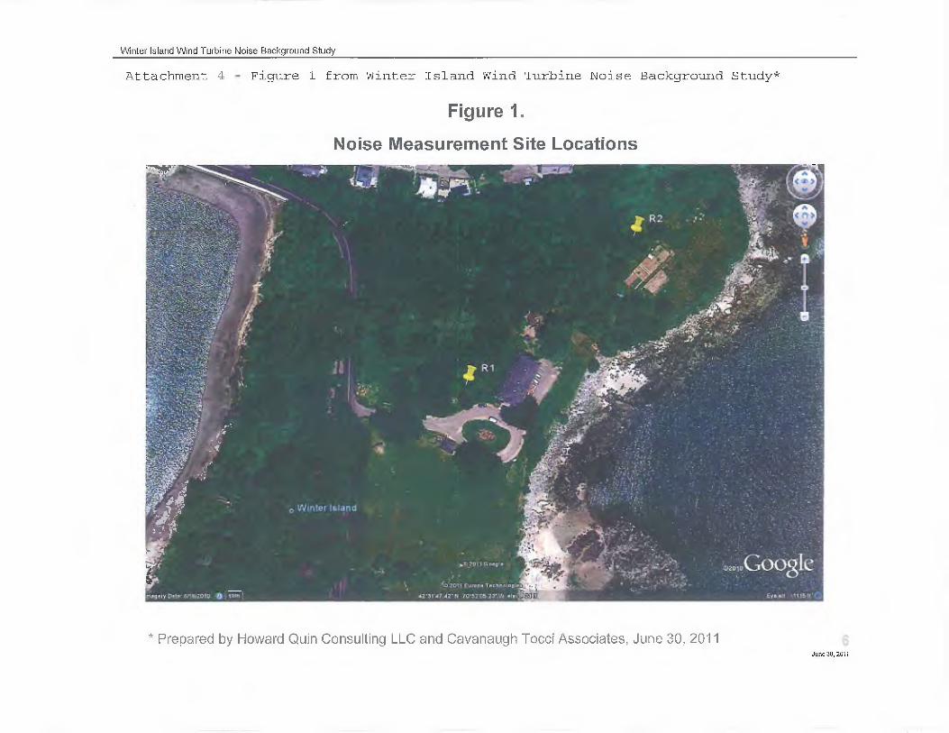
Winter Island Wind Turbine Noise Background Study
Attachment 4 - Figure 1 from Winter Island Wind Turbine Noise Background Study*
Figure 1.
Noise Measurement Site Locations
0 Winter Island
r°,99.1Y Cl.to br3:2010 tir L 1795 °
.M?0-11 Gooplie
-Z. 2011 Europa Tochnoloples
.1.7:31A7 .0- 141 75°52'0523'.4161 Coy!, Eyo olt • 1115 IC
* Prepared by Howard Quin Consulting LLC and Cavanaugh Tocci Associates, June 30, 2011June 30, 2011

First Supplement to Major Comprehensive Plan Application —Salem Harbor Redevelopment (SHR) Project (Transmittal Number X254064)
Attachment 5
Detailed Equipment Noise Specifications

Attachment 5
Detailed Equipment Noise Specifications
1.0 Combustion and Steam Power Train Components
The two combustion and steam turbines will be housed in an acoustically-treated structure, bothfor their general environmental protection and for abatement of noise. The turbine building willemploy acoustic treatments normally consisting of steel construction: a steel skin, mineral woolin the walls, and perforated metal interior walls for sound absorption (Sound Transmission Class(STC) rating of 46). The amount of noise radiated from the wall surfaces and ventilation systemof any given building is readily controllable over a reasonably wide range. A11 ventilationopenings and rooftop fans will be acoustically silenced and attenuated to maintain the acousticalintegrity of the envelope design targets. Machinery and personnel access into the building will bethrough high performance acoustic doors.
Sound Power Levels Used to Model Power Generation Components, dB (Flat)
Octave Band Center Frequency, hertz (Hz) Broadband(dBA)31 63 125 250 500 1000 2000 4000 8000
Turbine Generator(1 of2)
105 105 104 101 103 102 101 96 87 107
Load Compartment(1 of2)
129 121 120 109 103 100 97 94 92 108
TurbineCompartment(1 of 2)
111 113 107 106 103 101 106 102 97 110
Exhaust Diffuser(1 of2)
119 119 113 109 106 104 102 101 98 110
Stearn Turbine(1 of2)
112 112 108 107 106 101 96 94 93 107
Stearn TurbineGenerator(1 of 2)
106 106 105 102 104 103 102 97 88 108
Accessory Module(1 of2)
104 107 101 98 97 97 99 93 87 103
Air Inlet w/12 ftSilencer andAcoustically LinedWeather Hoods(1 of2)
111 112 108 84 68 69 69 65 63 93
Tetra Tech1
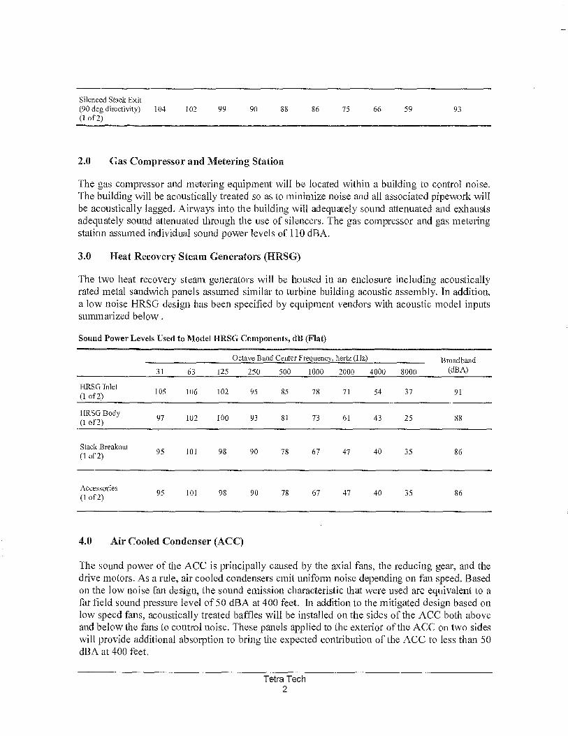
Silenced Stacic Exit(90 deg directivity) 104 102 99 90 88 86 75 66 59 93(1 of 2)
2.0 Gas Compressor and Metering Station
The gas compressor and metering equipment will be located within a building to control noise.The building will be acoustically treated so as to minimize noise and all associated pipework willbe acoustically lagged. Airways into the building will adequately sound attenuated and exhaustsadequately sound attenuated through the use of silencers. The gas compressor and gas meteringstation assumed individual sound power levels of 110 dBA.
3.0 Heat Recovery Steam Generators (HRSG)
The two heat recovery steam generators will be housed in an enclosure including acousticallyrated metal sandwich panels assumed similar to turbine building acoustic assembly. In addition,a low noise HRSG design has been specified by equipment vendors with acoustic model inputssummarized below .
Sound Power Levels Used to Model HRSG Components, dB (Flat)
Octave Band Center Frequency, hertz (11z) Broadband(dBA)31 63 125 250 500 1000 2000 4000 8000
HRSG Inlet(1 of 2)
105 106 102 95 85 78 71 54 37 91
HRSG Body(1 of 2)
97 102 100 93 81 73 61 43 25 88
Stack Breakout(1 of 2)
95 101 98 90 78 67 47 40 35 86
Accessories(1 of 2)
95 101 98 90 78 67 47 40 35 86
4.0 Air Cooled Condenser (ACC)
The sound power of the ACC is principally caused by the axial fans, the reducing gear, and thedrive motors. As a rule, air cooled condensers emit uniform noise depending on fan speed. Basedon the low noise fan design, the sound emission characteristic that were used are equivalent to afar field sound pressure level of 50 dBA at 400 feet. In addition to the mitigated design based onlow speed fans, acoustically treated baffles will be installed on the sides of the ACC both aboveand below the fans to control noise. These panels applied to the exterior of the ACC on two sideswill provide additional absorption to bring the expected contribution of the ACC to less than 50dBA at 400 feet.
Tetra Tech2
5.0 Transformers
Transformers generate the sound generally characterized as a low humming. There are threemain sound sources associated with a transformer: core noise, load noise, and noise generated bythe operation of the cooling equipment. The core vibrational noise is the principal noise sourceand does not vary significantly with electrical load. Transformers are designed and catalogued bymegavolt ampere ratings. Just as horsepower ratings designate the power capacity of an electricmotor, a transformer's MVA rating indicates its maximum power output capacity. The NationalElectrical Manufacturers Association published NEMA Standards TR1-1993, which establish themaximum noise level allowed for transformers based on the equipment's method of cooling itsdielectric fluid (air-cooled vs. oil-cooled) and the electric power rating. The transformers wouldlikely be rated at 320 MVA and would be 15-20 feet high. This corresponds to a standard, un-quieted NEMA 85 rated transformers for this site (Lw = 109 dBA). For the purposes of theacoustic modeling, a low noise NEMA rating of 70 was assumed (Lw = 95 dBA) to meet theacoustic design goal. In addition, sound barrier walls will extend 4 to 5 feet above the top of thetransformers and provide shielding to the receptors located on Derby Street to the west and theresidential area to the south.
Tetra Tech3