Embed Size (px)
Citation preview

Collectors
90-864260400 AUGUST 2009 Page 7F-1
7F
Exhaust SystemSection 7F - Collectors
Table of Contents
Hose Clamp Identification..................................................7F-2Tridon Hose Clamp.....................................................7F-2Norma Hose Clamp....................................................7F-2
Component Replacement..................................................7F-2
Through Propeller Exhaust.........................................7F-2Through the Transom Exhaust ..................................7F-4Silent Choice Exhaust System....................................7F-5
Collectors
Page 7F-2 90-864260400 AUGUST 2009
Lubricant, Sealant, AdhesivesTube Ref No. Description Where Used Part No.
Automotive weather-stripadhesive Air intake filter Obtain Locally
95 2-4-C with Teflon Air cylinder-to-silencer pipe flapper at clevis and pin 92-802859A 1
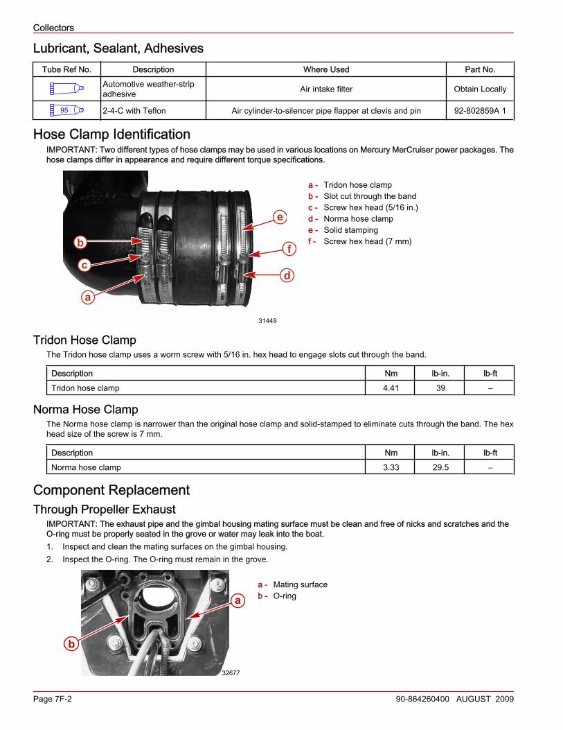
Hose Clamp IdentificationIMPORTANT: Two different types of hose clamps may be used in various locations on Mercury MerCruiser power packages. Thehose clamps differ in appearance and require different torque specifications.
a - Tridon hose clampb - Slot cut through the bandc - Screw hex head (5/16 in.)d - Norma hose clampe - Solid stampingf - Screw hex head (7 mm)
Tridon Hose ClampThe Tridon hose clamp uses a worm screw with 5/16 in. hex head to engage slots cut through the band.
Description Nm lb‑in. lb‑ftTridon hose clamp 4.41 39 –
Norma Hose ClampThe Norma hose clamp is narrower than the original hose clamp and solid‑stamped to eliminate cuts through the band. The hexhead size of the screw is 7 mm.
Description Nm lb‑in. lb‑ftNorma hose clamp 3.33 29.5 –
Component ReplacementThrough Propeller Exhaust
IMPORTANT: The exhaust pipe and the gimbal housing mating surface must be clean and free of nicks and scratches and theO‑ring must be properly seated in the grove or water may leak into the boat.1. Inspect and clean the mating surfaces on the gimbal housing.2. Inspect the O‑ring. The O‑ring must remain in the grove.
a - Mating surfaceb - O‑ring
a
b
e
31449
cd
f
b
32677
a

Collectors
90-864260400 AUGUST 2009 Page 7F-3
3. Inspect and clean the mating surfaces on the exhaust pipe.4. Install the exhaust pipe assembly using the 4 screws and lock‑washers. Tighten the screws to specification.
a - Exhaust Y pipe to gimbal housing bolt (4)b - Engine exhaust pipe
Description Nm lb‑in. lb‑ftExhaust pipe screw 34 – 25
Water Shutter ReplacementIMPORTANT: The exhaust system supplied by Mercury MerCruiser is compliant with ABYC Standard P‑1. If components areutilized in any portion of the exhaust system that modify the design of the supplied system, it is the boat builder's responsibility toensure that the new system complies with the ABYC Standards. Exhaust system connections to components other than suppliedby Mercury Marine must utilize two stainless steel clamps of minimum 13 mm (½ in.) in width at each joint.1. Remove and retain the intermediate exhaust pipe from the Y pipe.2. Remove and discard the water shutter and grommets from the Y pipe.3. Install the water shutter into the Y pipe. Ensure that the water shutter is seated into the rubber grommets.
a - Water shutterb - Rubber grommet
4. Install the exhaust tube and the intermediate exhaust pipe onto the exhaust Y pipe and secure with hose clamps. Tighten thehose clamps to specification.
a - Exhaust tubeb - Hose clampsc - Exhaust Y pipe
b 32680
a
b
b
a
18483
a b
cc
18530

Collectors
Page 7F-4 90-864260400 AUGUST 2009
Description Nm lb‑in. lb‑ftTridon hose clamp (exhaust tube) 4.41 39 –Norma hose clamp (exhaust tube) 3.33 29.5 –
Through the Transom ExhaustIMPORTANT: The block‑off plate and the gimbal housing mating surface must be clean and free of nicks and scratches and O‑ringmust be properly seated in the groove or water may leak into boat.IMPORTANT: A block‑off plate must be installed when using through the transom exhaust or below swim platform kits.1. Inspect and clean the mating surfaces on the gimbal housing.2. Inspect the O‑ring. The O‑ring must remain in the grove.
a - Mating surfaceb - O‑ring
3. Inspect and clean the mating surfaces on the block‑off plate.4. Install the block‑off plate assembly using the 4 screws and lock‑washers. Tighten the screws to specification.
a - Block‑off plateb - Boltsc - Lock‑washers
Description Nm lb‑in. lb‑ftExhaust block‑off plate bolts 34 – 25
Shutter Replacement1. Remove the exhaust hose clamps.2. Remove the exhaust hose.3. Install the new shutter. Tighten the screws and nuts securely.
b
32677
a
a32678
b
c
a
Collectors
90-864260400 AUGUST 2009 Page 7F-5
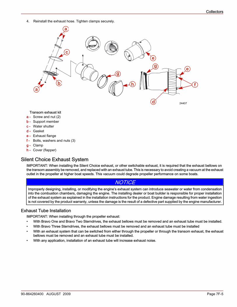
4. Reinstall the exhaust hose. Tighten clamps securely.
Transom exhaust kita - Screw and nut (2)b - Support memberc - Water shutterd - Gaskete - Exhaust flangef - Bolts, washers and nuts (3)g - Clamph - Cover (flapper)
Silent Choice Exhaust SystemIMPORTANT: When installing the Silent Choice exhaust, or other switchable exhaust, it is required that the exhaust bellows onthe transom assembly be removed, and replaced with an exhaust tube. This is necessary to avoid creating a vacuum at the exhaustoutlet in the propeller at higher boat speeds. This vacuum could degrade propeller performance on some boats.
NOTICEImproperly designing, installing, or modifying the engine’s exhaust system can introduce seawater or water from condensationinto the combustion chambers, damaging the engine. The installing dealer or boat builder is responsible for proper installationof the exhaust system as explained in the installation instructions for the product. Engine damage resulting from water ingestionis not covered by the product warranty, unless the damage is the result of a defective part supplied by the engine manufacturer.
Exhaust Tube InstallationIMPORTANT: When installing through the propeller exhaust:• With Bravo One and Bravo Two Sterndrives, the exhaust bellows must be removed and an exhaust tube must be installed.• With Bravo Three Sterndrives, the exhaust bellows must be removed and an exhaust tube must be installed• With an exhaust system that can be switched from either through the propeller or through the transom exhaust, the exhaust
bellows must be removed and an exhaust tube must be installed.• With any application, installation of an exhaust tube will increase exhaust noise.
24407
a
ab
c
d
e
e
f
gg
h

Collectors
Page 7F-6 90-864260400 AUGUST 2009
1. Remove and discard the clamps and exhaust bellows from the gimbal housing.
a - Exhaust bellowsb - Clamps
IMPORTANT: Failure to install the grounding clip can damage the exhaust tube due to corrosion. Always install the groundingclip.
2. Install the grounding clip on the exhaust tube.NOTE: Bellows adhesive is not used when installing an exhaust tube
3. Position the tube so that the "side" markings on the tube are facing toward the right and left sides.4. Install the clamp.5. Tighten the clamp securely.
a - Exhaust tubeb - Clampc - "Side" markingd - Exhaust tubee - Grounding clip
Air Tube Routing1. Route the air tubing from the air pump to the silencer valve cylinders. Do not route the air tubing close to hot surfaces.
Excessive heat will damage the air tubes.
Single enginea - Air tubeb - T‑fittingsc - Air pump assemblyd - Air tube to air cylinder—on each silencer valve
b
a20130
a
e
bc
d
20131
d
a
b
d
c 20132
Collectors
90-864260400 AUGUST 2009 Page 7F-7
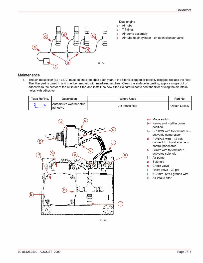
Dual enginea - Air tubeb - T‑fittingsc - Air pump assemblyd - Air tube to air cylinder—on each silencer valve
Maintenance1. The air intake filter (32‑17272) must be checked once each year. If the filter is clogged or partially clogged, replace the filter.
The filter pad is glued in and may be removed with needle‑nose pliers. Clean the surface in casting, apply a single dot ofadhesive to the center of the air intake filter, and install the new filter. Be careful not to coat the filter or clog the air intakeholes with adhesive.
Tube Ref No. Description Where Used Part No.Automotive weather-stripadhesive Air intake filter Obtain Locally
a - Mode switchb - Keyway—install in down
positionc - BROWN wire to terminal 3—
activates compressord - PURPLE wire—12 volt;
connect to 12‑volt source incontrol panel area
e - GRAY wire to terminal 1—activates solenoid
f - Air pumpg - Solenoidh - Check valvei - Relief valve—30 psij - 610 mm (2 ft.) ground wirek - Air intake filter
d d d
d
b 20134c
a
g
kh
i
f
b
a
d
e
j
cec
20136

Collectors
Page 7F-8 90-864260400 AUGUST 2009
2. Lubricate the air cylinder‑to‑silencer pipe flapper at the clevis and pin, as needed, with lubricant.
a - Clevis and pin
Tube Ref No. Description Where Used Part No.
95 2-4-C with Teflon Air cylinder-to-silencer pipe flapper at clevis and pin 92-802859A 1
a
20138