Embed Size (px)
Citation preview

2002
M
ercu
ry M
arin
e90
-102
3003
0 1
202
ME
RC
UR
Y J
ET
DR
IVE
– 2
00
240
This Jet Drive manufactured by Mercury Marine, Fond du Lac, Wiscon-sin, USA is subject to and complies with the applicable requirements ofthe following European Council directives and standards, as amended:
EMC Directive: 89/336/EEC; std. EN50081-1,SAE J551 (CISPR Pub. 12), EN 50082-1,IEC 61000 PT4-2, IEC 61000 PT4-3
Recreational Craft: 94/25/EC, std. ISO 8665
President, Mercury Marine, Fond du Lac, WI USA
This Jet Drive should not be put into service in the European Communityuntil the recreational craft into which it is to be incorporated has been de-clared in conformity with the above mentioned directives.
European Regulations Contact:Product Environmental Engineering Department, Mercury Marine, Fond du Lac, WI USA
Patrick C. Mackey
EPA Emissions RegulationsJet Drives manufactured by Mercury Marine in the United Statesare certified to the United States Environmental ProtectionAgency as conforming to the requirements of the regulations forthe control of air pollution from new Jet Drive motors. This certifi-cation is contingent on certain adjustments being set to factorystandards. For this reason, the factory procedure for servicingthe product must be strictly followed and, wherever practicable,returned to the original intent of the design. Maintenance, re-placement, or repair of the emission control devices andsystems may be performed by any marine engine repair es-tablishment or individual.Engines are labeled with an Emission Control Information decalas permanent evidence of EPA certification.
WARNINGThe engine exhaust from this product contains chemicalsknown to the state of California to cause cancer, birth de-fects or other reproductive harm.

0
Warranty MessageThe product you have purchased comes with a limited warrantyfrom Mercury Marine, the terms of the warranty are set forth in theWarranty Information Section of this manual. The warranty state-ment contains a description of what is covered, what is not covered,the duration of coverage, how to best obtain warranty coverage, im-portant disclaimers and limitations of damages , and other re-lated information. Please review this important information.
The description and specifications contained herein were in effect atthe time this manual was approved for printing. Mercury Marine,whose policy is one of continued improvement, reserves the right todiscontinue models at any time, to change specifications, designs,methods, or procedures without notice and without incurring obliga-tion.
Mercury Marine, Fond du Lac, Wisconsin U.S.A. Litho in U.S.A.
2002, Mercury MarineThe following are registered trademarks of Brunswick Corporation:AutoBlend, Force, Jet-Prop, Mariner, Merc, MerCathode, MerCruis-er, Mercury, Mercury Marine, Quicksilver, RideGuide and Thruster.

1
TABLE OF CONTENTSWarranty Information
Warranty Registration
United States and Canada 4. . . . . . . . . . . . . . . . . . . . . . . . . . . . . . . Outside United States and Canada 5. . . . . . . . . . . . . . . . . . . . . . .
Mercury Jet Products Limited Warranty 6. . . . . . . . . . . . . . . . . . . . .
3 Year Limited Warranty against Corrosion 8. . . . . . . . . . . . . . . . . .
Warranty Coverage and Exclusions 10. . . . . . . . . . . . . . . . . . . . . . . .
Transfer of Warranty 12. . . . . . . . . . . . . . . . . . . . . . . . . . . . . . . . . . . . .
General Information
Boater’s Responsibilities 13. . . . . . . . . . . . . . . . . . . . . . . . . . . . . . . Before Operating Your Jet Drive 13. . . . . . . . . . . . . . . . . . . . . . . . . Towing the Watercraft In Water 14. . . . . . . . . . . . . . . . . . . . . . . . . . Exhaust Emissions 15. . . . . . . . . . . . . . . . . . . . . . . . . . . . . . . . . . . . Lanyard Stop Switch 17. . . . . . . . . . . . . . . . . . . . . . . . . . . . . . . . . . . Protecting People In The Water 20. . . . . . . . . . . . . . . . . . . . . . . . . Wave and Wake Jumping 21. . . . . . . . . . . . . . . . . . . . . . . . . . . . . . Stopping The Boat In An Emergency 22. . . . . . . . . . . . . . . . . . . . . Mercury Jet Drive Remote Control 23. . . . . . . . . . . . . . . . . . . . . . . Selecting Accessories For Your Mercury Jet Drive 23. . . . . . . . . Safe Boating Suggestions 23. . . . . . . . . . . . . . . . . . . . . . . . . . . . . . Recording Serial Numbers 26. . . . . . . . . . . . . . . . . . . . . . . . . . . . . . Specifications 27. . . . . . . . . . . . . . . . . . . . . . . . . . . . . . . . . . . . . . . . . Component Identification 28. . . . . . . . . . . . . . . . . . . . . . . . . . . . . . .

2
TABLE OF CONTENTSFuel & Oil
Avoiding Fuel Flow Restrictions 29. . . . . . . . . . . . . . . . . . . . . . . . . Fuel Requirements 29. . . . . . . . . . . . . . . . . . . . . . . . . . . . . . . . . . . . Gasoline Recommendations 29. . . . . . . . . . . . . . . . . . . . . . . . . . . . Oil Recommendation 30. . . . . . . . . . . . . . . . . . . . . . . . . . . . . . . . . . Filling Remote Oil Tank 31. . . . . . . . . . . . . . . . . . . . . . . . . . . . . . . . Filling Engine Mounted Oil Reservoir Tank 31. . . . . . . . . . . . . . . . Filling Fuel Tank 31. . . . . . . . . . . . . . . . . . . . . . . . . . . . . . . . . . . . . . .
Features & Controls
Warning System 32. . . . . . . . . . . . . . . . . . . . . . . . . . . . . . . . . . . . . . Bilge Siphon 34. . . . . . . . . . . . . . . . . . . . . . . . . . . . . . . . . . . . . . . . . .
Operation
Pre-starting Check List 35. . . . . . . . . . . . . . . . . . . . . . . . . . . . . . . . . Special Operating Instructions 36. . . . . . . . . . . . . . . . . . . . . . . . . . Engine Break-in Procedure 40. . . . . . . . . . . . . . . . . . . . . . . . . . . . . Starting The Engine 41. . . . . . . . . . . . . . . . . . . . . . . . . . . . . . . . . . . Shifting 43. . . . . . . . . . . . . . . . . . . . . . . . . . . . . . . . . . . . . . . . . . . . . . Stopping The Engine 43. . . . . . . . . . . . . . . . . . . . . . . . . . . . . . . . . .
Maintenance
Mercury Jet Drive Care 44. . . . . . . . . . . . . . . . . . . . . . . . . . . . . . . . . Selecting Replacement Parts For Your Mercury Jet Drive 44. . . EPA Emissions Regulations 45. . . . . . . . . . . . . . . . . . . . . . . . . . . . Inspection And Maintenance Schedule 46. . . . . . . . . . . . . . . . . . . Cleaning A Clogged Water Intake 48. . . . . . . . . . . . . . . . . . . . . . . Fuel System 50. . . . . . . . . . . . . . . . . . . . . . . . . . . . . . . . . . . . . . . . . . Fuses 52. . . . . . . . . . . . . . . . . . . . . . . . . . . . . . . . . . . . . . . . . . . . . . . . Corrosion Control Anodes 53. . . . . . . . . . . . . . . . . . . . . . . . . . . . . .

3
TABLE OF CONTENTSBattery Inspection 53. . . . . . . . . . . . . . . . . . . . . . . . . . . . . . . . . . . . . Model 200 Hp – Spark Plug Inspection and Replacement 54. . . Model 240 Hp – Spark Plug Inspection and Replacement 55. . . Model 200 Hp – Flywheel Cover Removal And Installation 56. . Model 240 Hp – Flywheel Cover Removal And Installation 57. . Compressor Air intake Filter Model 200 Hp 58. . . . . . . . . . . . . . . Bolt Tensioner Pivot Shaft Lubrication 58. . . . . . . . . . . . . . . . . . . . Flushing The Cooling System 59. . . . . . . . . . . . . . . . . . . . . . . . . . . Draining Lubricant - Drive Housing 60. . . . . . . . . . . . . . . . . . . . . . Adding/Refilling Lubricant - Drive Housing 60. . . . . . . . . . . . . . . . Draining Lubricant - Stator Assembly 61. . . . . . . . . . . . . . . . . . . . Adding/Refilling Lubricant - Stator Assembly 62. . . . . . . . . . . . . . Bilge Siphon Inspection 63. . . . . . . . . . . . . . . . . . . . . . . . . . . . . . . . Submerged Engine 63. . . . . . . . . . . . . . . . . . . . . . . . . . . . . . . . . . . .
Storage
Storage Preparation 64. . . . . . . . . . . . . . . . . . . . . . . . . . . . . . . . . . .
Troubleshooting
Troubleshooting 67. . . . . . . . . . . . . . . . . . . . . . . . . . . . . . . . . . . . . . .
Owner Service Assistance
Local Repair Service 70. . . . . . . . . . . . . . . . . . . . . . . . . . . . . . . . . . . Service Away From Home 70. . . . . . . . . . . . . . . . . . . . . . . . . . . . . . Parts And Accessories Inquiries 70. . . . . . . . . . . . . . . . . . . . . . . . . Service Assistance 71. . . . . . . . . . . . . . . . . . . . . . . . . . . . . . . . . . . . Mercury Marine Service Offices 72. . . . . . . . . . . . . . . . . . . . . . . . .
Maintenance Log
Maintenance Log 73. . . . . . . . . . . . . . . . . . . . . . . . . . . . . . . . . . . . . .

4
WARRANTY INFORMATIONou1
Warranty RegistrationUNITED STATES AND CANADA
1. It is important that your selling dealer fills out the Warranty Registration Cardcompletely and mails it to the factory immediately upon sale of the new product.
2. It identifies name and address of the original purchaser, product model and seri-al number(s), date of sale, type of use and selling dealer’s code, name and ad-dress. The dealer also certifies that you are the original purchaser and user ofthe product.
3. Upon receipt of the Warranty Registration Card at the factory, you will be issueda plastic Owner Warranty Registration Card which is your only valid registrationidentification. It must be presented to the servicing dealer should warranty ser-vice be required. Warranty claims will not be accepted without presentation ofthis card.
4. A temporary Owner Warranty Registration Card will be presented to you whenyou purchase the product. It is valid only for 30 days from date of sale while yourplastic Owner Warranty Registration Card is being processed. Should yourproduct need service during this period, present the temporary registration cardto the dealer. He will attach it to your warranty claim form.
5. Because of your selling dealer’s continuing personal interest in your satisfac-tion, the product should be returned to him for warranty service.
6. If your plastic card is not received within 30 days from date of new product sale,please contact your selling dealer.
7. The limited warranty is not effective until the product is registered at the factory.
NOTE: Registration lists must be maintained by factory and dealeron marine products sold in the United States, should notification un-der the Federal Boat Safety Act be required.

5
WARRANTY INFORMATIONou2
Warranty RegistrationOUTSIDE THE UNITED STATES AND CANADA
1. It is important that your selling dealer fills out the Warranty Registration Cardcompletely and mails it to the distributor or Marine Power Service Center re-sponsible for administering the warranty registration/claim program for yourarea.
2. The Warranty Registration Card identifies your name and address, productmodel and serial number(s), date of sale, type of use and the selling distribu-tor’s/dealer’s code number, name and address. The distributor/dealer also cer-tifies that you are the original purchaser and user of the product.
3. A copy of the Warranty Registration Card, designated as the “Purchaser’sCopy”, MUST be given to you immediately after the card has been completelyfilled out by the selling distributor/dealer. This card represents your factory reg-istration identification, and should be retained by you for future use when re-quired. Should you ever require warranty service on this product, your dealermay ask you for the Warranty Registration Card to verify date of purchase andto use the information on the card to prepare the warranty claim form(s).
4. In some countries, the Marine Power Service Center will issue you a permanent(plastic) Warranty Registration Card within 30 days after receiving the “FactoryCopy” of the Warranty Registration Card from your distributor/dealer. If you re-ceive a plastic Warranty Registration Card, you may discard the “Purchaser’sCopy” that you received from the distributor/dealer when you purchased theproduct. Ask your distributor/dealer if this plastic card program applies to you.
5. For further information concerning the Warranty Registration Card and its rela-tionship to Warranty Claim processing, refer to the “International Warranty”.
IMPORTANT: Registration lists must be maintained by the fac-tory and dealer in some countries by law. It is our desire to haveALL products registered at the factory should it ever be neces-sary to contact you. Make sure your dealer/distributor fills outthe warranty registration card immediately and sends the facto-ry copy to the Marine Power International Service Center foryour area.

6
WARRANTY INFORMATIONou30
Mercury Jet Products Limited WarrantyUNITED STATES AND CANADA
Outside the United States and Canada – Check with your local distributor.
WHAT IS COVERED: Mercury Marine warrants its new Jet products to be free ofdefects in material and workmanship during the period described below.
DURATION OF COVERAGE: This Limited Warranty provides coverage for one (1)year from either the date the product is first sold, or the date on which the productis first put into service, whichever occurs first. The repair or replacement of parts, orthe performance of service under this warranty, does not extend the life of this war-ranty beyond its original expiration date. Unexpired warranty coverage can be trans-ferred to a subsequent purchaser upon proper re-registration of the product.
CONDITIONS THAT MUST BE MET IN ORDER TO OBTAIN WARRANTY COV-ERAGE: Warranty coverage is available only to retail customers that purchase froma Dealer authorized by Mercury Marine to distribute the product in the country inwhich the sale occurred, and then only after the Mercury Marine specified pre-deliv-ery inspection process is completed and documented. Warranty coverage becomesavailable upon proper registration of the product by the authorized dealer. Routinemaintenance outlined in the Operation and Maintenance Manual must be timely per-formed in order to maintain warranty coverage. Mercury Marine reserves the rightto make warranty coverage contingent upon proof of proper maintenance.
WHAT MERCURY WILL DO: Mercury’s sole and exclusive obligation under thiswarranty is limited to, at our option, repairing a defective part, replacing such partor parts with new or Mercury Marine certified re-manufactured parts, or refunding thepurchase price of the Mercury product. Mercury reserves the right to improve ormodify products from time to time without assuming an obligation to modify productspreviously manufactured.
HOW TO OBTAIN WARRANTY COVERAGE: The customer must provide Mercurywith a reasonable opportunity to repair, and reasonable access to the product forwarranty service. Warranty claims shall be made by delivering the product for in-spection to a Mercury dealer authorized to service the product. If purchaser cannotdeliver the product to such a dealer, written notice must be given to Mercury. We willthen arrange for the inspection and any covered repair. Purchaser in that case shallpay for all related transportation charges and/or travel time. If the service providedis not covered by this warranty, purchaser shall pay for all related labor and material,and any other expenses associated with that service. Purchaser shall not, unlessrequested by Mercury, ship the product or parts of the product directly to Mercury.The warranty registration card is the only valid registration identification and mustbe presented to the dealer at the time warranty service is requested in order to obtaincoverage.

7
WARRANTY INFORMATIONou38
Mercury Jet Products Limited WarrantyUNITED STATES AND CANADA
WHAT IS NOT COVERED: This limited warranty does not cover routine mainte-nance items, tune ups, adjustments, normal wear and tear, damage caused byabuse, abnormal use, use of a propeller or gear ratio that does not allow the engineto run in its recommended wide-open-throttle RPM range (see the Operation andMaintenance Manual), operation of the product in a manner inconsistent with therecommended operation/duty cycle section of the Operation and MaintenanceManual, neglect, accident, submersion, improper installation (proper installationspecifications and techniques are set forth in the installation instructions for the prod-uct), improper service, use of an accessory or part not manufactured or sold by us,jet pump impellers and wear rings or liners, operation with fuels, oils or lubricantswhich are not suitable for use with the product (see the Operation and MaintenanceManual), alteration or removal of parts, water entering the engine through the fuelintake, air intake or exhaust system, or damage to the product from insufficient cool-ing water caused by blockage of the cooling system by a foreign body, or runningthe engine out of water. Use of the product for racing or other competitive activity,or operating with racing modifications, at any point, even by a prior owner of the prod-uct, voids the warranty.
Expenses related to haul-out, launch, towing, storage, telephone, rental, inconve-nience, slip fees, insurance coverage, loan payments, loss of time, loss of income,or any other type of incidental or consequential damages are not covered by this war-ranty. Also, expenses associated with the removal and/or replacement of boat parti-tions or material caused by boat design for access to the product are not coveredby this warranty.
No individual or entity, including Mercury Marine authorized dealers, has been givenauthority by Mercury Marine to make any affirmation, representation or warranty re-garding the product, other than those contained in this limited warranty, and if made,shall not be enforceable against Mercury Marine.
For additional information regarding events and circumstances covered by this war-ranty, and those that are not, see the Warranty Coverage section of the Operationand Maintenance Manual, incorporated by reference into this warranty.
DISCLAIMERS AND LIMITATIONS:
THE IMPLIED WARRANTIES OF MERCHANTABILITY AND FITNESS FOR A PARTICU-
LAR PURPOSE ARE EXPRESSLY DISCLAIMED. TO THE EXTENT THAT THEY CANNOT
BE DISCLAIMED, THE IMPLIED WARRANTIES ARE LIMITED IN DURATION TO THE LIFE
OF THE EXPRESS WARRANTY. INCIDENTAL AND CONSEQUENTIAL DAMAGES ARE
EXCLUDED FROM COVERAGE UNDER THIS WARRANTY. SOME STATES/COUNTRIES
DO NOT ALLOW FOR THE DISCLAIMERS, LIMITATIONS AND EXCLUSIONS IDENTIFIED
ABOVE, AS A RESULT, THEY MAY NOT APPLY TO YOU. THIS WARRANTY GIVES YOU
SPECIFIC LEGAL RIGHTS, AND YOU MAY ALSO HAVE OTHER LEGAL RIGHTS WHICH
VARY FROM STATE TO STATE AND COUNTRY TO COUNTRY.

8
WARRANTY INFORMATIONou37
3 Year Limited Warranty Against CorrosionWHAT IS COVERED: Mercury Marine warrants that each new Mercury, Mariner,Mercury Racing, Sport Jet, Mercury Jet Drive, Tracker by Mercury Marine Outboard,MerCruiser Inboard or sterndrive engine (Product) will not be rendered inoperativeas a direct result of corrosion for the period of time described below.
DURATION OF COVERAGE: This limited corrosion warranty provides coverage forthree (3) years from either the date the product is first sold, or the date on which theproduct is first put into service, whichever occurs first. The repair or replacement ofparts, or the performance of service under this warranty does not extend the life ofthis warranty beyond its original expiration date. Unexpired warranty coverage canbe transferred to subsequent (noncommercial use) purchaser upon proper re-regis-tration of the product.
CONDITIONS THAT MUST BE MET IN ORDER TO OBTAIN WARRANTY COV-ERAGE: Warranty coverage is available only to retail customers that purchase froma Dealer authorized by Mercury Marine to distribute the product in the country inwhich the sale occurred, and then only after the Mercury Marine specified pre-deliv-ery inspection process is completed and documented. Warranty coverage becomesavailable upon proper registration of the product by the authorized dealer. Corrosionprevention devices specified in the Operation and Maintenance Manual must be inuse on the boat, and routine maintenance outlined in the Operation and Mainte-nance Manual must be timely performed (including without limitation the replace-ment of sacrificial anodes, use of specified lubricants, and touch-up of nicks andscratches) in order to maintain warranty coverage. Mercury Marine reserves theright to make warranty coverage contingent upon proof of proper maintenance.
WHAT MERCURY WILL DO: Mercury’s sole and exclusive obligation under thiswarranty is limited to, at our option, repairing a corroded part, replacing such part orparts with new or Mercury Marine certified re-manufactured parts, or refunding thepurchase price of the Mercury product. Mercury reserves the right to improve ormodify products from time to time without assuming an obligation to modify productspreviously manufactured.
HOW TO OBTAIN WARRANTY COVERAGE: The customer must provide Mercurywith a reasonable opportunity to repair, and reasonable access to the product forwarranty service. Warranty claims shall be made by delivering the product for in-spection to a Mercury dealer authorized to service the product. If purchaser cannotdeliver the product to such a dealer, written notice must be given to Mercury. We willthen arrange for the inspection and any covered repair. Purchaser in that case shallpay for all related transportation charges and/or travel time. If the service providedis not covered by this warranty, purchaser shall pay for all related labor and material,and any other expenses associated with that service. Purchaser shall not, unlessrequested by Mercury, ship the product or parts of the product directly to Mercury.The warranty registration card is the only valid registration identification and mustbe presented to the dealer at the time warranty service is requested in order to obtaincoverage.

9
WARRANTY INFORMATIONou39
3 Year Limited Warranty Against CorrosionWHAT IS NOT COVERED: This limited warranty does not cover electrical systemcorrosion; corrosion resulting from damage, corrosion which causes purely cosmet-ic damage, abuse or improper service; corrosion to accessories, instruments, steer-ing systems; corrosion to factory installed outboard jet drive unit; damage due to ma-rine growth; product sold with less than a one year limited Product warranty;replacement parts (parts purchased by customer); products used in a commercialapplication. Commercial use is defined as any work or employment related use ofthe product, or any use of the product which generates income, for any part of thewarranty period, even if the product is only occasionally used for such purposes.
Corrosion damage caused by stray electrical currents (on-shore power connections,nearby boats, submerged metal) is not covered by this corrosion warranty andshould be protected against by the use of a corrosion protection system, such as theMercury Precision Parts or Quicksilver MerCathode system and/or Galvanic Isola-tor. Corrosion damage caused by improper application of copper base anti-foulingpaints is also not covered by this limited warranty. If anti-fouling protection is re-quired, Tri-Butyl-Tin-Adipate (TBTA) base anti-fouling paints are recommended onOutboard, Jet Drives and MerCruiser boating applications. In areas where TBTAbase paints are prohibited by law, copper base paints can be used on the hull andtransom. Do not apply paint to the Outboard, Jet Drives or MerCruiser product. Inaddition, care must be taken to avoid an electrical interconnection between the war-ranted product and the paint. For MerCruiser product, an unpainted gap of at least1.5 inches (38mm) should be left around the transom assembly. Refer to the Opera-tion and Maintenance Manual for additional details.
For additional information regarding events and circumstances covered by this war-ranty, and those that are not, see the Warranty Coverage section of the Operationand Maintenance Manual, incorporated by reference into this warranty.
DISCLAIMERS AND LIMITATIONS:THE IMPLIED WARRANTIES OF MERCHANTABILITY AND FITNESS FOR APARTICULAR PURPOSE ARE EXPRESSLY DISCLAIMED. TO THE EXTENTTHAT THEY CANNOT BE DISCLAIMED, THE IMPLIED WARRANTIES ARE LIM-ITED IN DURATION TO THE LIFE OF THE EXPRESS WARRANTY. INCIDENTALAND CONSEQUENTIAL DAMAGES ARE EXCLUDED FROM COVERAGE UN-DER THIS WARRANTY. SOME STATES/COUNTRIES DO NOT ALLOW FORTHE DISCLAIMERS, LIMITATIONS AND EXCLUSIONS IDENTIFIED ABOVE,AS A RESULT, THEY MAY NOT APPLY TO YOU. THIS WARRANTY GIVES YOUSPECIFIC LEGAL RIGHTS, AND YOU MAY ALSO HAVE OTHER LEGALRIGHTS WHICH VARY FROM STATE TO STATE AND COUNTRY TO COUNTRY.

10
WARRANTY INFORMATIONop3
Warranty Coverage and ExclusionsThe purpose of this section is to help eliminate some of the more common misunder-standings regarding warranty coverage. The following information explains some ofthe types of services that are not covered by warranty.
Keep in mind that warranty covers repairs that are needed within the warranty periodbecause of defects in material and workmanship. Installation errors, accidents, nor-mal wear, and a variety of other causes that affect the product are not covered.
Warranty is limited to defects in material or workmanship, but only when the consum-er sale is made in the country to which distribution is authorized by us.
Should you have any questions concerning warranty coverage, contact your autho-rized dealer. They will be pleased to answer any questions that you may have.
GENERAL EXCLUSIONS FROM WARRANTY
1. Minor adjustments and tune-ups, including checking, cleaning or adjustingspark plugs, ignition components, carburetor settings, filters, belts, controls,and checking lubrication made in connection with normal services.
2. Damage caused by neglect, lack of maintenance, accident, abnormal operationor improper installation or service.
3. Haul-out, launch, towing charges, removal and/or replacement of boat parti-tions or material because of boat design for necessary access to the product,all related transportation charges and/or travel time, etc. Reasonable accessmust be provided to the product for warranty service. Customer must deliverproduct to an authorized dealer.
4. Additional service work requested by customer other than that necessary to sat-isfy the warranty obligation.
5. Labor performed by other than an authorized dealer may be covered only underfollowing circumstances: When performed on emergency basis (providingthere are no authorized dealers in the area who can perform the work requiredor have no facilities to haul out, etc., and prior factory approval has been givento have the work performed at this facility).
6. All incidental and/or consequential damages (storage charges, telephone orrental charges of any type, inconvenience or loss of time or income) are theowner’s responsibility.

11
WARRANTY INFORMATIONop8
Warranty Coverage and Exclusions7. Use of other than Mercury Precision or Quicksilver replacement parts when
making warranty repairs.
8. Oils, lubricants or fluids changed as a matter of normal maintenance is custom-er’s responsibility unless loss or contamination of same is caused by productfailure that would be eligible for warranty consideration.
9. Participating in or preparing for racing or other competitive activity or operatingwith a racing type components.
10. Engine noise does not necessarily indicate a serious engine problem. If diagno-sis indicates a serious internal engine condition which could result in a failure,condition responsible for noise should be corrected under the warranty.
11. Pump unit and/or impeller damage caused by either striking a submerged ob-ject, or rocks, stones or foreign objects being drawn through the water intakegrate is considered a marine hazard.
12. Water entering engine through the fuel intake, air intake or exhaust system. orsubmersion.
13. Failure of any parts caused by lack of cooling water, which results from startingengine out of water, foreign material blocking inlet or ingestion of sand and/ormud.
14. Use of fuels and lubricants which are not suitable for use with or on the product.Refer to the Maintenance Section.
15. Our limited warranty does not apply to any damage to our products caused bythe installation or use of parts and accessories which are not manufactured orsold by us. Failures which are not related to the use of those parts or accesso-ries are covered under warranty if they otherwise meet the terms of the limitedwarranty for that product.

12
WARRANTY INFORMATIONoq2
Transfer Of WarrantyThe limited warranty is transferable to a subsequent purchaser, butonly for the remainder of the unused portion of the limited warranty.This will not apply to products used for commercial applications.
DIRECT SALE BY OWNER
The second owner can be registered as the new owner and retain theunused portion of the limited warranty by sending the former owner’splastic Owner Warranty Registration Card and a copy of the bill ofsale to show proof of ownership. In the United States and Canada,mail to:Mercury MarineW6250 W. Pioneer RoadP.O. Box 1939Fond du Lac, WI 54936-1939Attn: Warranty Registration Department
A new Owner Warranty Registration Card will be issued with the newowner’s name and address. Registration records will be changed onthe factory computer registration file.
There is no charge for this service.
For products purchased outside the United States and Canada, con-tact the distributor in your country, or the Mercury Marine Service Of-fice closest to you.

13
GENERAL INFORMATIONoba5
Boater’s ResponsibilitiesThe operator (driver) is responsible for the correct and safe operationof the boat and safety of its occupants and general public. It is strong-ly recommended that each operator (driver) read and understandthis entire manual before operating the boat.
Be sure at least one additional person on board is instructed in thebasics of starting and operating the Mercury Jet Drive and boat han-dling in case the driver is unable to operate the boat.obq6
Before Operating Your Mercury Jet DriveRead this manual carefully. Learn how to operate your Mercury JetDrive properly. If you have any questions, contact your dealer.
Safety and operating information that is practiced along with usinggood common sense can help prevent personal injury and productdamage.
This manual as well as safety labels posted on the Mercury Jet Driveuse the following safety alerts to draw your attention to special safetyinstructions that should be followed.
DANGERDANGER – Immediate hazards which WILL result in severepersonal injury or death.
WARNINGWARNING – Hazards or unsafe practices which COULD resultin severe personal injury or death.
CAUTIONCAUTION – Hazards or unsafe practices which could result inminor injury or product or property damage.
(continued on next page)

14
GENERAL INFORMATIONobq6
Before Operating Your Mercury Jet Drive(Continued)Read this manual carefully. Learn the difference in handling charac-teristics between a Mercury Jet Drive boat and a propeller drivenboat including:
• Steering at low power/throttle - unlike propeller driven boats, theMercury Jet Drive boat tends to lose steering control as less wateris drawn in and expelled. Increase power/throttle slightly to regainsteering.
• Maneuverability - the Mercury Jet Drive is highly maneuverableat higher speeds; more so, than propeller driven boats. Use cau-tion when turning to prevent spin-outs.
• Steering in reverse - unlike propeller driven boats, turning thesteering wheel turns the bow of the boat in the same direction.
If you have any questions, contact your dealer.
Safety and operating information that is practiced along with usinggood common sense can help prevent personal injury and productdamage.obw2
Towing the Watercraft in WaterIf towing a stranded Mercury Jet Drive powered watercraft in water,the towing speed must be slow. Keep the towing speed at or aroundidle speed.
Keeping the towing speed slow will prevent water from being forcedup through the exhaust system and into the engine. Water enteringthe engine can cause damage to internal engine parts.

15
GENERAL INFORMATIONgob4
Courtesy of ABYC1obi4
Exhaust EmissionsBE ALERT TO CARBON MONOXIDE POISONING
Carbon monoxide is present in the exhaust fumes of all internal com-bustion engines including the outboards, stern drives, jet drives andinboard engines that propel boats, as well as the generators thatpower various boat accessories. Carbon monoxide is a deadly gasthat is odorless, colorless and tasteless.
Early symptoms of carbon monoxide poisoning which should not beconfused with seasickness or intoxication, include headache, dizzi-ness, drowsiness, and nausea.
WARNINGAvoid the combination of a running engine and poor ventila-tion. Prolonged exposure to carbon monoxide in sufficientconcentration can lead to unconsciousness, brain damage, ordeath.
GOOD VENTILATION
Ventilate passenger area, open side curtains, or forward hatches toremove fumes.
1 Example of desired air flow through the boat.

16
GENERAL INFORMATIONgob39
a
c
b
d
Courtesy of ABYC2obi3
Exhaust Emissions (Continued)POOR VENTILATION
Under certain running and/or wind conditions, permanently enclosedor canvas enclosed cabins or cockpits with insufficient ventilationmay draw in carbon monoxide. Install one or more carbon monoxidedetectors in your boat.
Although the occurrence is rare, on a very calm day, swimmers andpassengers in an unclosed area of a stationary boat that contains oris near a running engine may be exposed to a hazardous level ofcarbon monoxide.
2 Examples of Poor Ventilation:
While boat is stationary
a. Running the engine when the boat is moored in a confinedspace.
b. Mooring close to another boat that has its engine running.
While boat is moving
c. Running the boat with the trim angle of the bow too high.
d. Running the boat with no forward hatches open (stationwagon effect).

17
GENERAL INFORMATIONgob8
2
1
obg9
Lanyard Stop Switch1 The purpose of a lanyard stop switch is to turn off the engine
when the operator moves far enough away from the operator’sposition (as in accidental ejection from the operator’s position) toactivate the switch.
2 The lanyard is a cord usually between 4 and 5 feet (1220 and1524 mm) in length when stretched out with an element on oneend made to be placed onto the switch and a snap on the otherend for attaching to the operator. The lanyard is coiled to makeits at-rest condition as short as possible so as to minimize thelikelihood of lanyard entanglement with nearby objects. It ismade as long as it is in its stretched condition to minimize thelikelihood of accidental activation should the operator choose tomove around in an area close to the normal operator’s position.If it is desired to have a shorter lanyard, wrap the lanyard aroundthe operator’s wrist or leg, or tie a knot in the lanyard.
(continued on next page)

18
GENERAL INFORMATIONLanyard Stop Switch (Continued)Read the following Safety Information before proceeding.
Important Safety Information: The purpose of a lanyard stopswitch is to stop the engine when the operator moves far enoughaway from the operator’s position to activate the switch. This wouldoccur if the operator accidentally falls overboard or moves within theboat a sufficient distance from the operator’s position. Accidentalejections and falls overboard are more likely to occur in certain typesof boats such as low sided sport boats or bass boats, andhigh-performance boats. Accidental ejections and falls overboardare also likely to occur as a result of poor operating practices suchas sitting on the back of the seat or gunwale at planing speeds,standing at planing speeds, sitting on elevated fishing boat decks,operating at planing speeds in shallow or obstacle-infested waters,releasing your grip on a steering wheel that is pulling in one direction,drinking alcohol or consuming drugs, or daring, high-speed boatmaneuvers.
While activation of the lanyard stop switch will stop the engineimmediately, a boat will continue to coast for some distancedepending upon the velocity and degree of any turn at shut-down.However, the boat will not complete a full circle. While the boat iscoasting, it can cause injury to anyone in the boat’s path as seriouslyas the boat would when under power.
We strongly recommend that other occupants be instructed onproper starting and operating procedures should they be required tooperate the engine in an emergency (e.g. if the operator isaccidentally ejected).
WARNINGShould the operator fall out of the boat, the possibility ofserious injury or death from being run over by the boat can begreatly reduced by stopping the engine immediately. Alwaysproperly connect both ends of the stop switch lanyard – to thestop switch and the operator.
(continued on next page)

19
GENERAL INFORMATIONLanyard Stop Switch (Continued)Accidental or unintended activation of the switch during normaloperation is also a possibility. This could cause any, or all, of thefollowing potentially hazardous situations:
1. Occupants could be thrown forward due to unexpected loss offorward motion – a particular concern for passengers in the frontof the boat who could be ejected over the bow and possibly struckby the hull.
2. Loss of power and directional control in heavy seas, strongcurrent or high winds.
3. Loss of control when docking.
WARNINGAvoid serious injury or death from deceleration forcesresulting from accidental or unintended stop switchactivation. The boat operator should never leave theoperator’s station without first disconnecting the stop switchlanyard from the operator.

20
GENERAL INFORMATIONgob3
obh4
Protecting People In The WaterWHILE YOU ARE CRUISING
It is very difficult for a person standing or floating in the water to takequick action to avoid a boat heading in their direction even at slowspeed.
Always slow down and exercise extreme caution any time you areboating in an area where there might be people in the water.
Avoid shallow water or where any loose material such as sand,shells, seaweed, grass, tree branches, etc. can be sucked in andexpelled from the the pump as a high speed projectile.
WHILE BOAT IS STATIONARY
Stop the Mercury Jet Drive engine immediately whenever anyone inthe water is near your boat. The Mercury Jet Drive is always drawingwater through the water intake grate when the engine is running.Stay away from the water intake located under the stern (back) of theboat and never insert an object into the water intake or water outletnozzle when the engine is running.
WARNINGAvoid injury resulting from contacting the rotating impeller orhaving your hair, clothing or loose objects drawn into thewater intake and wrapping around the impeller shaft. Stayaway from the water intake and never insert an object into thewater int ake or water outlet nozzle when the engine is running.

21
GENERAL INFORMATIONgob4
obu1
Wave And Wake JumpingOperating recreational boats over waves and wakes is a natural partof boating. However, when this activity is done with sufficient speedto force the boat hull partially or completely out of the water, certainhazards arise, particularly when the boat re-enters the water.
The primary concern is the boat changing direction while in the midstof the jump. In such case the landing may cause the boat to veer vio-lently in a new direction. Such a sharp change in direction can causeoccupants to be thrown out of their seats, or out of the boat.
There is another less common hazardous result from allowing yourboat to launch off a wave or wake. If the bow of your boat pitchesdown far enough while airborne, upon water contact it may penetrateunder the water surface and “submarine” for an instant. This will bringthe boat to a nearly instantaneous stop and can send the occupantsflying forward. The boat may also steer sharply to one side.
WARNINGAvoid serious injury or death from being thrown within or outof a boat when it lands after jumping a wave or wake. Avoidwave or wake jumping whenever possible. Instruct all occu-pants that if a wake or wave jump occurs, get low and hang onto any boat hand hold.

22
GENERAL INFORMATIONobo5
Stopping The Boat In An EmergencyYour jet powered boat has emergency stopping capability unique tothis form of propulsion.
In an emergency, putting the remote control handle into reverse andapplying reverse throttle can rapidly slow down your boat and reducethe stopping distance. Keep in mind, however, that such a maneuvermay cause occupants in the boat to be thrown forward or even outof the boat.
WARNINGUsing the emergency stopping capability of your Mercury JetDrive unit will slow down your boat in an emergency. Howeverkeep in mind, sudden stopping may cause the occupants inthe boat to be thrown forward or even out of the boat. Thisaction may result in serious injury or death.
Emergency stopping may cause the bow to submerge and take ona large quantity of water if too much power is applied in reverse. Thisprocedure should be practiced in a safe area, gradually increasethrottle in reverse until bow is just above the waterline.

23
GENERAL INFORMATIONobr3
Mercury Jet Drive Remote ControlThe remote control connected to your Mercury Jet Drive must beequipped with a start-in-gear protection device. This prevents theengine from starting when the Mercury Jet Drive is in forward orreverse.
WARNINGAvoid serious injury or death from a sudden unexpectedacceleration when starting your Mercury Jet Drive. The designof this Jet Drive requires that the remote control used with itmust have a built in “start-in-gear” protection device.
obs4
Selecting Accessories For Your Mercury JetDriveGenuine Mercury Precision or Quicksilver Accessories have beenspecifically designed and tested for your Mercury Jet Drive. Theseaccessories are available from Mercury Marine dealers.
Some accessories not manufactured or sold by Mercury Marine arenot designed to be safely used with your Mercury Jet Drive operatingsystem. Acquire and read the installation, operation andmaintenance manuals for all your selected accessories.
WARNINGCheck with your dealer before installation of accessories. Themisuse of acceptable accessories or the use of unacceptableaccessories can result in serious injury, death or productfailure.
obk7
Safe Boating SuggestionsIn order to safely enjoy the waterways, familiarize yourself with localand other government boating regulations and restrictions, andconsider the following suggestions.
Use flotation devices. Have an approved personal flotation deviceof suitable size for each person aboard (it is the law) and have itreadily accessible.
(continued on next page)

24
GENERAL INFORMATIONSafe Boating Suggestions (Continued)Do not overload your boat. Most boats are rated and certified formaximum load (weight) capacities (refer to your boat capacity plate).If in doubt, contact your dealer or the boats manufacturer.
Perform safety checks and required maintenance . Follow aregular schedule and ensure that all repairs are properly made.
Know and obey all nautical rules and laws of the waterways .Boat operators should complete a boating safety course. Coursesare offered in the U.S.A. by (1) The U.S. Coast Guard Auxiliary, (2)The Power Squadron, (3) The Red Cross and (4) your state boatinglaw enforcement agency. Inquiries may be made to the BoatingHot-line, 1-800-368-5647 or the Boat U.S. Foundation informationnumber 1-800-336-BOAT.
Make sure everyone in the boat is properly seated . Don’t allowanyone to sit or ride on any part of the boat that was not intended forsuch use. This includes backs of seats, gunwales, transom, bow,decks, raised fishing seats, any rotating fishing seat; anywhere thatsudden unexpected acceleration, sudden stopping, unexpected lossof boat control or sudden boat movement could cause a person to bethrown overboard or into the boat.
Never be under the influence of alcohol or drugs while boating(it is the law). They impair your judgment and greatly reduce yourability to react quickly.
Prepare other boat operators. Instruct at least one person on boardin the basics of starting and operating the Mercury Jet Drive and boathandling in case the driver becomes disabled or falls overboard.
Passenger boarding. Stop the engine whenever passengers areboarding, unloading or are near the back (stern) of the boat. Justshifting the Mercury Jet Drive into neutral is not sufficient. The jetdrive is always drawing water through the water intake grate whenthe engine is running.
Be alert. The operator of the boat is responsible by law to “maintaina proper lookout by sight (and hearing).” The operator must have anunobstructed view particularly to the front. No passengers, load, orfishing seats should block the operators view when operating theboat above idle speed.
(continued on next page)

25
GENERAL INFORMATIONSafe Boating Suggestions (Continued)Never drive your boat directly behind a water skier in case theskier falls. As an example, your boat traveling at 25 miles per hour(40 km/hr) in 5 seconds will overtake a fallen skier who was 200 feet(61m) in front of you.
Watch fallen skiers. When using your boat for water skiing or similaractivities, always keep a down skier on the operator’s side of the boatwhile returning to attend the skier. The operator should always havethe down skier in sight and never back up to the skier or anyone inthe water.
Avoid running over ski ropes. Ski ropes can get sucked up into thepump water inlet and can cause the pump to become inoperable.
Report accidents. Boat operators are required by law to file a Boat-ing Accident Report with their state boating law enforcement agencywhen their boat is involved in certain boating accidents. A boating ac-cident must be reported if (1) there is loss of life or probable loss oflife, (2) there is personal injury requiring medical treatment beyondfirst aid, (3) there is damage to boats or other property where thedamage value exceeds $500.00 or (4) there is complete loss of theboat. Seek further assistance from local law enforcement.
Avoid shallow water conditions. Avoid operating your Mercury JetDrive in very shallow water or where there is a noticeable amount offloating debris or weeds. Always be in at least 3 feet (A) of water,especially when accelerating from idle speeds. Any loose materialsuch as sand, shells, stones, seaweed, grass, etc. can be drawn upby the pump and may cause any of the following problems:
• engine overheat• loss of steering• objects expelled from the pump as high-speed projectiles• Pump damage
goe8
26
GENERAL INFORMATIONgob51
20XX
XX
a b
c
d
a
d
OEXXXXXXX
OEXXXXXXX
a
dOEXXXXXXX
200 Hp 240 Hp
200 & 240 Hp
obl10
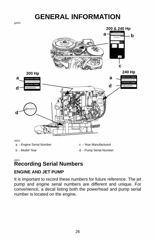
a - Engine Serial Number c - Year Manufactured
b - Model Year d - Pump Serial Number
obl11
Recording Serial NumbersENGINE AND JET PUMP
It is important to record these numbers for future reference. The jetpump and engine serial numbers are different and unique. Forconvenience, a decal listing both the powerhead and pump serialnumber is located on the engine.

27
GENERAL INFORMATIONobm85
Specifications
Model 200 240
Horsepower 200 240
Kilowatts 149.1 178.9
Full Throttle RPM Range 5150 - 5650 5500 - 6000
Idle Speed RPM Range 900 - 1000 1000 - 1100
Number of Cylinders 6
Piston Displacement 153 cu. in. (2507 cc)
Cylinder Bore 3.501 in. (88.925 mm)
Stroke 2.650 in. (67.31 mm)
Spark Plug NGK IZFR5G NGK BPZ8HS10
Spark Plug Gap .030 in. (0.8 mm) .040 in. (1.0 mm)
Recommended Gasoline Refer to Fuel Section
Recommended Oil Refer to Fuel Section
Model 200 HpBattery Rating (minimum)
1000 Marine Cranking Amps (MCA)or 750 Cold Cranking Amps (CCA)
Model 240 HpBattery Rating (minimum)
670 Marine Cranking Amps (MCA)or 520 Cold Cranking Amps (CCA)

28
GENERAL INFORMATIONgob52
234
56
1
1
8
7
Model 200 Hp Shownobn28
Component Identification
1. Water Intake 5. Reverse Gate
2. Wear Ring 6. Rudder
3. Stator 7. Bilge Siphon
4. Anodes 8. Expansion Chamber

29
FUEL & OILoes1
Avoiding Fuel Flow RestrictionsIMPORTANT: Adding components to the fuel supply system asin filters, valves, fittings, etc. may restrict the fuel flow and couldcause engine stalling at low speed, and/or a lean fuel conditionat high RPM, that could cause engine damage.oea1
Fuel RequirementsDo not use pre-mixed gas and oil in this engine. Use a clean and freshrecommended gasoline during engine break-in and after enginebreak-in.oeb2
Gasoline RecommendationsUNITED STATES AND CANADA
Use a major brand of automotive unleaded gasoline with a minimumposted octane rating of 87. Mid-grade automotive gasolines thatcontain fuel injector cleaner are preferred for added internal enginecleanliness. Leaded gasoline is not recommended.
INTERNATIONAL
Use a major brand of automotive unleaded gasoline with a minimumposted octane rating of 90RON. Automotive gasolines that containfuel injector cleaner are preferred for added internal enginecleanliness. Leaded gasoline is acceptable in areas where unleadedgasoline is not available.

30
FUEL & OILoeb8
Gasoline Recommendations (Continued)ALCOHOL IN GASOLINE
We do not recommend the use of gasoline which contains alcoholbecause of the possible adverse effect the alcohol may have on thefuel system. In general, if only gasoline containing alcohol is avail-able, it must not contain more than 10% ethanol or 5% methanol.
If gasoline containing alcohol is used or if you suspect the presenceof alcohol in your gasoline, increase your inspection of the fuelsystem, visually checking for fuel leaks or abnormalities.
Gasoline containing alcohol may cause the following problems toyour outboard and fuel system:• Corrosion of metal parts.• Deterioration of elastomers and plastic parts.• Wear and damage of internal engine parts.• Starting and operating difficulties.• Vapor lock or fuel starvation.Some of these adverse effects are due to the tendency of gasolinecontaining alcohol to absorb moisture from the air, resulting in a phaseof water and alcohol which separates from the gasoline in the fuel tank.
The adverse effects of alcohol are more severe with methanol andare worse with increasing content of alcohol.oec12
Oil RecommendationModel 200 HpMercury or Quicksilver Optimax/DFI 2-Cycle engine oil isrecommended for your engine. If Optimax/DFI 2-Cycle engine oil isnot available, we recommend using Mercury or Quicksilver TC-W3Premium Plus 2-Cycle Oil. Severe engine damage may result fromuse of an inferior oil.Model 240 HpMercury or Quicksilver Premium TC-W3 2-cycle oil is recommendedfor your engine. For added protection and lubrication, Mercury orQuicksilver Premium Plus TC-W3 2-cycle oil is recommended. IfMercury or Quicksilver outboard oil is not available, substituteanother brand of 2-cycle outboard oil that is NMMA Certified TC-W3.Severe engine damage may result from use of an inferior oil.

31
FUEL & OILgoe8
21oeo1
Filling Remote Oil Tank1 Remove the filler cap and fill with the specified oil. Oil tank
capacity is 3 gallons (11.5 liters). Replace filler cap and tightensecurely.
The remote oil tank is pressurized by engine crankcase pressure.The remote oil tank feeds the engine mounted oil reservoir. Theengine mounted oil reservoir supplies oil to the oil injection pump.
IMPORTANT: Always make sure the oil tank caps are threadedon tight. An air leak will prevent oil flow to the engine.
Filling Engine Mounted Oil Reservoir TankNOTE: Filling this tank is only necessary if the oil level should everdrop and the low oil warning system is activated.
2 Remove the filler cap and fill to the top with the specified oil.Replace filler cap and tighten securely.
oee9
Filling Fuel Tank
WARNINGAvoid serious injury or death from a gasoline fire or explosion.Always stop the engine and DO NOT smoke or allow openflames or sparks in the area while filling fuel tanks.
Fill fuel tanks outdoors away from heat, sparks, and open flames.
Always stop engine before refilling tanks.
Do not completely fill the fuel tanks. Leave approximately 10% of thetank volume unfilled. Fuel will expand in volume as its temperaturerises and can leak under pressure if the tank is completely filled.

32
FEATURES & CONTROLSogb71
Warning SystemWARNING HORN SIGNALS
When the key switch is turned to the ON position, the horn will turnon for a moment as a test to tell you the horn is working.
The warning horn will emit either a continuous beep or intermittentshort beeps. This will alert the operator and help identify the followinglisted situations (see chart below). For visual display of the specificengine functions and for additional engine data, refer to SmartCraftProduct information on next page.
Warning HornFunction Sound Description
Start Up One Beep Normal System Test
Low Oil Reserve Four Beeps every2 Minutes
Oil level is low in the engine mounted oilreservoir tank. Refill the engine mountedoil reservoir tank along with the remoteoil tank. Refer to Fuel & Oil Section.
Water In Fuel Four Beeps every2 Minutes
Water in the water-separating fuel filterreaches the full level. Water can beremoved from the filter. Refer to Main-tenance Section for filter removal.
Cooling SystemProblem
ContinuousEngine Guardian System is activated.Power limit will very with level of over-heat. Stop engine and check water in-take for obstruction.
Oil Level is CriticallyLow
ContinuousEngine Guardian System is activated.Power limit will allow a fast idle. The oillevel is critically low in the enginemounted oil reservoir tank. Refill theengine mounted oil reservoir tank alongwith the remote oil tank. Refer to Fueland Oil Section.
Oil Pump Failure ContinuousEngine Guardian System is activated.Power limit will allow a fast idle. Thewarning horn is activated if the oilpump should ever stop functioningelectrically. No lubricating oil is beingsupplied to the engine.
Sensor out of RangeContinuous
Engine Guardian System is activated.Power limit may activate at full throttlespeed.
Intermittent BeepEngine Guardian System is activated.Power limit may restrict engine speedto idle.

33
FEATURES & CONTROLSogb89
Warning SystemENGINE GUARDIAN SYSTEMThe Engine Guardian System monitors the critical sensors on theengine for any early indications of problems. The system will respondto a problem by emitting a continuous beep and/ or reducing enginepower in order to provide engine protection.If Guardian System is activated, the system must be RESET beforethe engine will operate at higher speeds. Moving throttle lever backto idle position resets the system.
SMARTCRAFT PRODUCT
A Mercury SmartCraft System instrument package can bepurchased for this Mercury Jet Drive. A few of the functions theinstrument package will display are engine rpm, coolant temp, waterpressure, battery voltage, fuel consumption and engine operatinghours.
The SmartCraft Instrument package will also aid in Engine Guardiandiagnostics. The SmartCraft Instrument package will display criticalengine alarm data and potential problems.

34
FEATURES & CONTROLSgog131
a
b
Model 200 Hp Shownosa5
Bilge SiphonThe Mercury Jet Drive incorporates an automatic bilge siphoningfeature. The bilge siphon is working whenever the engine is runningabove idle speeds. Maximum performance of the bilge siphon isrealized above 3,000 rpm.
Water exiting the jet pump nozzle creates a suction or vacuum in thehose (a) attached to the nozzle. The hose is routed to and positionedin the bilge, on the side of the jet tunnel.
The bilge siphon system incorporates a siphon break (b) whichprevents water from siphoning back into the boat when the engineis turned off. This siphon break must be located at the highest pointof the hose routing and must be above the waterline.
The siphon break (b) requires periodic inspection to ensure properoperation. The air hole (0.020 in.) must remain open and free fromobstruction.

35
OPERATIONofa8
Pre-Starting Check List
❐ Operator knows safe navigation, boating and operatingprocedures.
❐ An approved personal flotation device of suitable size for eachperson aboard and readily accessible (it is the law).
❐ Know your boats maximum load capacity. Look at the boatcapacity plate.
❐ Check fuel supply.
❐ Check oil level in oil reservoir.
❐ Make sure the boat drain plug is installed.
❐ Tell someone where you are going and when you expect to return.
❐ It is illegal to operate a boat while under the influence of alcoholor drugs.
❐ Know the waters you will be using; tides, currents, sand bars,rocks and other hazards.
❐ Make inspection checks listed in the Inspection and MaintenanceSchedule. Refer to Maintenance Section.
❐ Operate the bilge blower for at least 5 minutes to remove anyexplosive fumes from the engine compartment. If boat is notequipped with a bilge blower, open engine hatch and leave openwhile starting engine.
❐ Before launching, examine the Mercury Jet Drive pump inlet forobstructions which may prevent pumping of water.
❐ Check steering for free operation.
❐ Check for debris around the rudder and reverse gate which mayjam or hinder operation.

36
OPERATIONofb14
SPECIAL OPERATING INSTRUCTIONSOPERATING ON THE WATER
A Mercury Jet Drive boat has substantially different handling charac-teristics compared to a propeller driven boat. It is suggested that youadjust yourself to these characteristics by experimentation in openwater at both high and low speeds.
Although Mercury Jet Drive applications do not pose some of therisks associated with exposed propeller driven systems, thefollowing steps must always be kept in mind.
1 The Mercury Jet Drive works by drawing water up thru the bottomwater intake and redirects it to the rear for forward thrust. TheMercury Jet Drive has a steerable rudder that can direct the jetthrust to the right or left. If the engine stops or the water flow isblocked, this will stop the jet thrust causing the boat to slow to astop. However, while slowing there will be no ability to steer assteering is dependent on jet thrust.
CAUTIONIf the Mercury Jet Drive is tied to a dock, make sure that longropes are not in the water when starting the engine. Ropes canbe drawn up into the jet pump intake causing damage.
2 Avoid the use of neutral or reverse when skiing to minimize thechance that the ski rope will be drawn up into the jet pump intake.Turn the engine off when waiting for skiers. Make sure ski ropeis clear before starting engine.
3 Avoid weed areas or traverse weed areas at high speeds. Ifunavoidable, keep the boat on plane until cleared of weededarea.
NOTE: When operating in weed infested areas carry a QuicksilverWeed Rake P/N 830116A1.
(continued on next page)
37
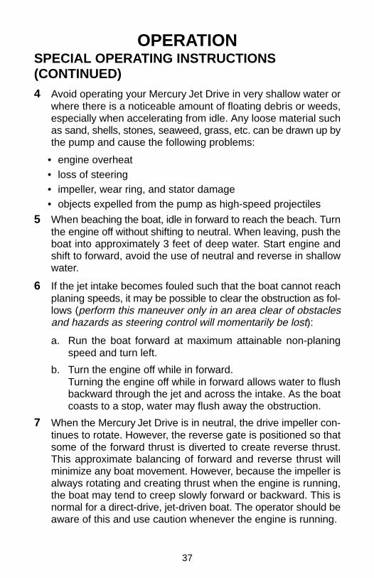
OPERATIONSPECIAL OPERATING INSTRUCTIONS(CONTINUED)4 Avoid operating your Mercury Jet Drive in very shallow water or
where there is a noticeable amount of floating debris or weeds,especially when accelerating from idle. Any loose material suchas sand, shells, stones, seaweed, grass, etc. can be drawn up bythe pump and cause the following problems:
• engine overheat• loss of steering• impeller, wear ring, and stator damage• objects expelled from the pump as high-speed projectiles
5 When beaching the boat, idle in forward to reach the beach. Turnthe engine off without shifting to neutral. When leaving, push theboat into approximately 3 feet of deep water. Start engine andshift to forward, avoid the use of neutral and reverse in shallowwater.
6 If the jet intake becomes fouled such that the boat cannot reachplaning speeds, it may be possible to clear the obstruction as fol-lows (perform this maneuver only in an area clear of obstaclesand hazards as steering control will momentarily be lost):
a. Run the boat forward at maximum attainable non-planingspeed and turn left.
b. Turn the engine off while in forward.Turning the engine off while in forward allows water to flushbackward through the jet and across the intake. As the boatcoasts to a stop, water may flush away the obstruction.
7 When the Mercury Jet Drive is in neutral, the drive impeller con-tinues to rotate. However, the reverse gate is positioned so thatsome of the forward thrust is diverted to create reverse thrust.This approximate balancing of forward and reverse thrust willminimize any boat movement. However, because the impeller isalways rotating and creating thrust when the engine is running,the boat may tend to creep slowly forward or backward. This isnormal for a direct-drive, jet-driven boat. The operator should beaware of this and use caution whenever the engine is running.

38
OPERATIONSPECIAL OPERATING INSTRUCTIONS(CONTINUED)
WARNINGAvoid injury, death or property damage resulting fromcollision due to loss of directional control. Directional controlis derived from the water jet thrust. Thus, caution should beexercised when maneuvering at higher speeds in areas wheredebris (weeds, sand, gravel, etc.) could be picked up into theMercury Jet Drive. This can cut off or reduce the jet thrust,thereby directly affecting boat directional control. Boatdirectional control can also be substantially reduced or lostaltogether by a sudden loss of power such as running out ofgas, by quickly backing off throttle, turning off ignition switchor activating lanyard stop switch. Remember your ability totake evasive action is dependent on sufficient jet thrust tocontrol your boat.
8 The Mercury Jet Drive is always drawing water into the housingwhen the engine is running. DO NOT operate the Mercury JetDrive with the grate removed from the water intake. Keep yourhands, feet, hair, loose clothing, life jackets, etc. away from thewater intake in the bottom of the boat. Never insert an object intothe water intake or water outlet nozzle when the engine isrunning.
WARNINGAvoid injury resulting from contacting the rotating impeller orhaving your hair, clothing or loose objects drawn into thewater intake and wrapping around the impeller shaft. Stayaway from the water intake and never insert an object into thewater int ake or water outlet nozzle when the engine is running.

39
OPERATIONSPECIAL OPERATING INSTRUCTIONS(CONTINUED)OPERATING IN FREEZING TEMPERATURES
If there is a chance of ice forming on the water, the boat should beremoved from the water and the Mercury Jet Drive drained complete-ly of water. If ice should form at the water level inside the Mercury JetDrive, it will block water flow to the engine causing possible damage.
OPERATING IN SALT WATER OR POLLUTED WATER
We recommend that you flush the internal water passages of yourengine with fresh water after each time you operate in salt or pollutedwater. This will prevent a build up of deposits from clogging the waterpassages. Refer to flushing procedure in the Maintenance Section.
Your boat and Mercury Jet Drive should be removed from the waterwhen not in use.
Wash down exterior and interior of the Mercury Jet Drive with freshwater after each use. Each month, spray Quicksilver or MercuryPrecision Corrosion Guard on external metal surfaces (do not spray oncorrosion control anodes as this will reduce the effectiveness of theanodes).
OPERATING AT HIGH ALTITUDES
Your engine automatically compensates for high elevation changes.

40
OPERATIONofd16
Engine Break-in ProcedureNOTE: Do not use pre-mixed gas and oil in this engine. Use straightgasoline during engine break-in and after engine break-in.
The engine break-in procedure is important to ensure properperformance and maximum life from the engine. The followingbreak-in procedure allows the internal engine parts to wear-in evenly.Incorrect engine break-in can shorten the engine life.
The engine automatically receives extra oil during the first hours ofoperation. For most boaters this extra oil mode will be complete inabout ten hours.
First hour
• Allow engine to warm-up for 30-60 seconds.• Avoid continuous operation at idle speed for more then ten
minutes.• Run the engine the majority of time between 3000 and 4500 RPM
approximately three quarter throttle.• Vary engine speed; change engine speed approximately every 2
minutes.• Short bursts of full throttle for periods up to 10 seconds are
acceptable.Next three hours
• Change engine speed every 10 minutes.

41
OPERATIONgof117
1 2ofe63
Starting The EngineBefore starting, read Pre-Starting Check List, Special OperatingInstructions and Engine Break-In Procedure in the first part of thisOperation Section.
1 Before starting, operate bilge blower for at least 5 minutes toremove any explosive fumes from the engine compartment. Ifboat is not equipped with a bilge blower, open engine hatch orcover and leave open while starting engine.
WARNINGTo prevent a possible explosion, operate the bilge blower forat least 5 minutes before starting the engine. If the enginecompartment is not equipped with a blower, open the enginecover and leave open while starting engine.
It is also advisable to use your nose to detect any fuel fumes. Shouldfuel fumes be detected, the open fuel source should be located andeliminated.
2 Do not start the Mercury Jet Drive unless water is supplied to theengine. Make sure the water intake is submerged. If using theFlushing Attachment, make sure the water is flowing through theengine at its maximum flow before starting. When using theflushing attachment Do Not run the engine above idle speeds.
CAUTIONNever start or run the Mercury Jet Drive without water circulat-ing through the cooling system to prevent damage to the unit.
42
OPERATIONgof118
53
N
4
N
Dual Handle Single Handle
Shift
Throttle
ofe64
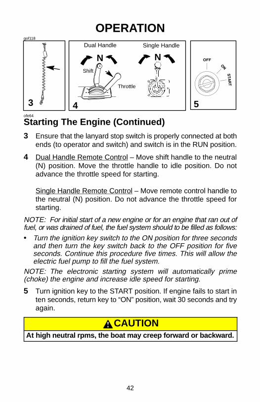
Starting The Engine (Continued)3 Ensure that the lanyard stop switch is properly connected at both
ends (to operator and switch) and switch is in the RUN position.
4 Dual Handle Remote Control – Move shift handle to the neutral(N) position. Move the throttle handle to idle position. Do notadvance the throttle speed for starting.
Single Handle Remote Control – Move remote control handle tothe neutral (N) position. Do not advance the throttle speed forstarting.
NOTE: For initial start of a new engine or for an engine that ran out offuel, or was drained of fuel, the fuel system should to be filled as follows:• Turn the ignition key switch to the ON position for three seconds
and then turn the key switch back to the OFF position for fiveseconds. Continue this procedure five times. This will allow theelectric fuel pump to fill the fuel system.
NOTE: The electronic starting system will automatically prime(choke) the engine and increase idle speed for starting.
5 Turn ignition key to the START position. If engine fails to start inten seconds, return key to “ON” position, wait 30 seconds and tryagain.
CAUTIONAt high neutral rpms, the boat may creep forward or backward.

43
OPERATIONgof119
41-3
FN
R FN
R
Dual Handle Single Handle
onc3
Shifting1 Your Mercury Jet Drive has three shift positions to provide opera-
tion in Forward, Neutral and Reverse:
a. Forward (F) - has all the water clearing the reverse gate forforward thrust and forward boat motion.
b. Neutral (N) - has the reverse gate covering half the wateroutlet nozzle to distribute thrust both forward and backward.The drive impeller continues to rotate and the boat may tendto creep in one direction. This is normal for a direct-drivejet-driven boat. Use caution whenever the engine isrunning.
c. Reverse (R) - has the reverse gate covering the entire wateroutlet nozzle to divert the exiting water stream forward to re-verse boat motion.
2 After shifting into forward or reverse, advance the throttle leverfurther to increase speed.
NOTE: Operators must practice the stopping maneuver to becomefamiliar with jet-drive handling.
3 To stop the boat normally, gradually reduce speed before shiftingto neutral position. Use caution when shifting and turningsince some loss of steering control will result. Remember,steering control is dependent on thrust produced.
ofm8
Stopping The Engine4 Reduce engine speed until boat comes to a complete stop. Shift
Mercury Jet Drive to neutral position. Turn ignition key to OFFposition.
44
MAINTENANCEomw5
Mercury Jet Drive CareTo keep your Mercury Jet Drive in the best operating condition, it isimportant that the Mercury Jet Drive receive the periodic inspectionsand maintenance listed in the Inspection and Maintenance Schedule.We urge you to have it maintained properly to ensure your safety andthat of your passengers and also to retain its dependability.
Record maintenance performed in Maintenance Log at the back ofthis book. Save all maintenance work orders and receipts.
WARNINGNeglected inspection and maintenance service of yourMercury Jet Drive or attempting to perform maintenance orrepair on your Mercury Jet Drive if you are not familiar with thecorrect service and safety procedures could cause personalinjury, death or product failure.
Selecting Replacement Parts For Your Jet DriveWe recommend using original Mercury Precision or Quicksilverreplacement parts and Genuine Lubricants.
WARNINGUsing a replacement part that is inferior to the original partcould result in personal injury, death, or product failure.

45
MAINTENANCEoti9
EPA Emissions RegulationsAll new jet drives manufactured by Mercury Marine are certified to theUnited States Environmental Protection Agency as conforming to therequirements of the regulations for the control of air pollution fromnew outboard motors. This certification is contingent on certainadjustments being set to factory standards. For this reason, thefactory procedure for servicing the product must be strictly followedand, wherever practicable, returned to the original intent of thedesign. Maintenance, replacement, or repair of the emissioncontrol devices and systems may be performed by any marineSI engine repair establishment or individual.oti6
EMISSION CERTIFICATION LABEL
An emission certification label, showing emission levels and enginespecifications directly related to emissions, is placed on the engineat time of manufacture.
a
cd
b
e
f
hi
g
a - Idle Speed b - Engine Horsepowerc - Piston Displacementd - Date of Manufacturee - Valve Clearance (if Applicable)
f - Family Numberg - Maximum Emission Output for the Engine Family h - Timing Specificationi - Recommended Spark Plug & Gap
oti7
OWNER RESPONSIBILITY
The owner/operator is required to have engine maintenance performedto maintain emission levels within prescribed certification standards.
The owner/operator is not to modify the engine in any manner thatwould alter the horsepower or allow emissions levels to exceed theirpredetermined factory specifications.

46
MAINTENANCEohd59
Inspection And Maintenance ScheduleBEFORE EACH USE
1. Check that lanyard stop switch stops the engine.
2. Visually inspect the fuel system for deterioration or leaks.
3. Check the engine compartment and use your nose to detect anyfuel fumes.
4. Check throttle, shift and steering system for binding or loosecomponents.
AFTER EACH USE
1. Wash off all salt deposits with fresh water if operating in saltwater.
2. Flush out the engine cooling system if operating in salt or pollutedwaters or sandy locations. (page 59)
EVERY 10 HOURS OR ONCE A MONTH
1. Check bilge siphon system. (page 63)
2. Inspect cable bellows: worn, rubbing, or leaking.
3. Inspect battery and connections. (page 53)
4. Check tightness of bolts, nuts and other fasteners.
5. Check Exhaust hoses for holes or distortion due to overheating.
47
MAINTENANCEInspection And Maintenance Schedule(Continued)EVERY 50 HOURS OF USE OR ONCE A MONTH
1. Check level and condition of drive housing and stator lubricant.(page 60 – 62)
2. Check corrosion control anodes. (page 53)
3. Check tightness of bolts, nuts and other fasteners.
EVERY 100 HOURS OF USE OR ONCE A SEASON
1. Replace spark plugs at first 100 hours or first year. After that,inspect spark plugs every100 hours or once yearly. Replacespark plugs as needed. (page 54, 55)
2. Drain and replace drive housing lubricant. (page 60)
3. Drain and replace stator housing lubricant. (page 61, 62)
4. Remove impeller and lubricate impeller shaft with Quicksilver orMercury Precision 2-4-C w/Teflon to prevent impeller fromseizing to the shaft.
5. Lubricate the belt tenioner pivot shaft. (Page 58)
6. Replace engine fuel line filter. (page 50)
7. Replace Water separating fuel filter (Page 51)
8. Replace compressor air intake filter – Model 200 Hp. (Page 58)
BEFORE PERIODS OF STORAGE
1. Refer to Storage Preparation. (page 64)

48
MAINTENANCEgoh212
1
a
c
b
omx10
Clearing A Clogged Water Intake1 The Hydro-Surge (weed) grate (a) and casted aluminum grate
(b) are intended for general use. The Rock grate (c) should beused if running in rocky, shallow conditions.
MANUAL CLEARING
If weeds or debris clog the water intake, the blockage must be com-pletely cleaned out to return the unit to proper running order.
WARNINGAvoid injury or death resulting from contacting the rotatingimpeller or having your hair, clothing or loose objects drawninto the water intake and wrapping around the impeller shaft.Do not attempt to clean debris from the Mercury Jet Drivewhile the engine is running.
NOTE: When operating in weed infested areas carry a QuicksilverWeed Rake P/N 830116A1.
1. Turn off the engine because the pump impeller is still spinningand pumping water while in neutral. Remove the key from theignition switch to prevent accidental starting.
(continued on next page)

49
MAINTENANCEClearing A Clogged Water Intake (Continued)2. Use a weed rake or manually remove the blockage from the
water intake grate.
3. Clean debris from the entire Mercury Jet Drive unit (water intake,impeller and nozzle). If the Jet Drive cannot be easily cleaned,the boat should be returned to the trailer or to a boat lift for haulout before further work is performed.
4. It may be necessary to remove the water intake grate from thebottom of the Mercury Jet Drive to clean debris from the waterintake. Remove the water intake grate by removing four screws.Reinstall the water intake grate with four screws. Apply Loctite242 to the threads of the screws. Torque front screws to 200 lb.in. (23 N·m), torque rear screws to 75 lb. in. (8.5 N·m).
IMPORTANT: DO NOT operate the Mercury Jet Drive without thewater intake grate installed.omx9
HYDRO-SURGE GRATE
The Hydro-Surge grate is spring loaded. If the intake gets plugged,the pump suction will pull open the grate and the water will push theblockage pass the grate and clear the intake.
If operating your boat at slow speeds in weedy areas, the intake gratecan become plugged with weeds. A plugged grate will cause thepump to cavitate during acceleration (over-revving without thrustingthe boat).
If the grate becomes plugged, slowly advance the throttle to get theboat up on plane, making sure not to cavitate the pump. Continue toadvance the throttle until the boat is running at top speed. The forceof the water should clear the pump of any remaining weeds.
However, in extreme cases, a weed rake or manual clearing may berequired. Refer to Manual Clearing.

50
MAINTENANCEgoh213
1
a
Model 200 Hp Shownohh5
Fuel System
WARNINGAvoid serious injury or death from gasoline fire or explosion.Carefully follow all fuel system service instructions. Alwaysstop the engine and DO NOT smoke or allow open flames orsparks in the area while servicing any part of the fuel system.
Before servicing any part of the fuel system, stop engine anddisconnect the battery. Drain the fuel system completely. Use anapproved container to collect and store fuel. Wipe up any spillageimmediately. Material used to contain spillage must be disposed ofin an approved receptacle. Any fuel system service must beperformed in a well ventilated area. Inspect any completed servicework for sign of fuel leakage.
FUEL LINE INSPECTION
Visually inspect the fuel line for cracks, swelling, leaks, hardness, orother signs of deterioration or damage. If any of these conditions isfound, the fuel line must be replaced.
FUEL LINE FILTER
1 Replace the fuel filter (a) once a season or every 100 hours ofuse.
IMPORTANT: Visually inspect for fuel leakage from the filterconnections.

51
MAINTENANCEgoh110
2a
Model 200 Hp Shownohh6
Fuel System (Continued)WATER SEPARATING FUEL FILTER
NOTE: The warning system will turn on when water in the fuel filterreaches the full level. Refer to “Warning System” in Features &Controls Section.
2 This filter removes moisture and also debris from the fuel. If thefilter becomes filled with water, the water can be removed. If thefilter becomes plugged with debris, the filter must be replacedwith a new filter.
Remove and replace filter as follows:
a. Turn ignition key switch to OFF position.
b. Disconnect wire at bottom of filter. Remove filter (a) by turningthe filter in the direction of the arrow (clockwise). Tip the filterto drain fluid in a suitable container.
c. Lubricate the sealing ring on the filter with oil. Thread on thefilter and tighten securely by hand. Reconnect the wire to thefilter.

52
MAINTENANCEgoh121
1
a
c
b
d
Model 200 Hp
Model 240 HpModel 240 Hp
e
Front
Starboard Side
e
Port Side
Model 200 Hp
Starboard Side
ohj17
FusesIMPORTANT: Always carry spare fuses.
The electrical wiring circuits on the engine are protected from overloadby fuses in the wiring. If a fuse is blown, try to locate and correct the causeof the overload. If the cause is not found, the fuse may blow again.
1 Open the fuse holder and look at the silver colored band insidethe fuse. If band is broken, replace the fuse. Replace fuse witha new fuse with the same rating.
The fuses and circuits are identified as follows:
a. SmartCraft Data Bus Circuit – 15 AMP Fuse.
b. Accessories – 20 AMP Fuse.
c. Ignition Coil Circuit – 20 AMP Fuse.
d. Electric Fuel Pump/ECM Driver Power/Oil Pump Circuit –SFE 20 AMP Fuse.
e. Fuel Lift Pump – Fuse holder – 3 AMP Fuse for Models 240Hp, 5 AMP Fuse for Models 200 Hp

53
MAINTENANCEgoh228
a1ohk19
Corrosion Control Anodes1 Your Mercury Jet Drive has three corrosion control anodes (a).
One of the anodes is installed on the bottom of the nozzle, oneinstalled on the reverse gate and one is installed under therudder. An anode helps protect the Mercury Jet Drive againstgalvanic corrosion by sacrificing its metal to be slowly erodedinstead of the Mercury Jet Drive metals.
Each anode requires periodic inspection especially in salt waterwhich will accelerate the erosion. To maintain this corrosion protec-tion, always replace the anode before it is completely eroded. Neverpaint or apply a protective coating on the anode as this will reduceeffectiveness of the anode.ohn1
Battery InspectionThe battery should be inspected at periodic intervals to ensureproper engine starting capability.
IMPORTANT: Read the safety and maintenance instructionswhich accompany your battery.
1. Turn off the engine before servicing the battery.
2. Add water as necessary to keep the battery full.
3. Make sure the battery is secure against movement.
4. Battery cable terminals should be clean, tight, and correctlyinstalled. Positive to positive and negative to negative.
5. Make sure the battery is equipped with a nonconductive shieldto prevent accidental shorting of battery terminals.

54
MAINTENANCEgoh151
1-3 4 5 6
ab
ohm17
Model 200 Hp – Spark Plug Inspection andReplacement
WARNINGAvoid serious injury or death from fire or explosion caused bydamaged spark plug boots (b). Damaged spark plug boots canemit sparks. Sparks can ignite fuel vapors in the enginecompartment. To avoid damaging spark plug boots, do notuse any sharp object or metal tool such as pliers, screwdriver,etc. to remove or install spark plug boots.
1 Loosen hoses from the expansion chamber (a). Remove the sixnuts that secures the expansion chamber. Remove the expan-sion chamber.
2 Open J-clips to move fuel/air lines out of the way.3 Remove the spark plug boots (b) by twisting the rubber boots
slightly and pull off. See WARNING above.4 Remove the spark plugs to inspect. Replace spark plug if electrode
is worn or the insulator is rough, cracked, broken, blistered or fouled.5 Set the spark plug gap. See Specification Chart in General
Information Section.6 Before installing spark plugs, clean away dirt on the spark plug
seats. Install plugs finger tight, and tighten 1/4 turn or torque to20 lb. ft. (27 N·m).
7 Inspect expansion chamber gasket on adaptor plate. Do notremove the gasket from the adaptor plate. Replace if damaged.
8 Reinstall the expansion chamber. Torque nuts to 20 lb. ft (27N·m). Reinstall hoses to the expansion chamber and secure withclamps
9 Inspect system for leaks.

55
MAINTENANCEgoh14
1 2 3
a
ohm18
Model 240 Hp – Spark Plug Inspection andReplacement
WARNINGAvoid serious injury or death from fire or explosion caused bydamaged spark plug boots (a). Damaged spark plug boots canemit sparks. Sparks can ignite fuel vapors in the enginecompartment. To avoid damaging spark plug boots, do notuse any sharp object or metal tool such as pliers, screwdriver,etc. to remove or install spark plug boots.
1 Remove the spark plug boots (a) by twisting the rubber bootsslightly and pull off. See WARNING above.
2 Remove the spark plugs to inspect. Replace spark plug if elec-trode is worn or the insulator is rough, cracked, broken, blisteredor fouled.
3 Set the spark plug gap. See Specification Chart in General In-formation Section.
4 Before installing spark plugs, clean away dirt on the spark plugseats. Install plugs finger tight, and tighten 1/4 turn or torque to20 lb. ft. (27 N·m).

56
MAINTENANCEgoh117
b
a c1-2
d
ohg7
Model 200 Hp – Flywheel Cover Removal AndInstallationRemoval
WARNINGAvoid injury from contact with moving components beneaththe flywheel cover. Do not attempt to remove or reinstall theflywheel cover when engine is running. Keep your hands, hair,clothing, tools, and other objects away from the moving com-ponents beneath the flywheel cover.
1 Detach strap (d). Remove cover by lifting off from back of engine.
IMPORTANT: Make sure debris does not enter the air intakeopening or air compressor inlet.
Installation2 Install flywheel cover as follows:
a. Place cover onto the air intake grommet (a).
b. Push the cover down onto the side pin (b) and then the airintake tube (c) for the air compressor.
c. Attach retaining strap (d) to the cover.
IMPORTANT: Make sure the flywheel cover is securely in placeand the air intake hole for the air compressor is aligned with theair intake tube grommet. Replace pin grommets if worn.

57
MAINTENANCEgoh117
a
1-2ohg8
Model 240 Hp – Flywheel Cover Removal AndInstallationRemoval
WARNINGAvoid injury from contact with moving components beneaththe flywheel cover. Do not attempt to remove or reinstall theflywheel cover when engine is running. Keep your hands, hair,clothing, tools, and other objects away from the moving com-ponents beneath the flywheel cover.
1 Remove flywheel cover by lifting off from back of engine.
IMPORTANT: Make sure debris does not enter the air intakeopening.
Installation2 Install flywheel cover as follows:
a. Place cover onto the air intake grommet (a) and push thecover down onto the pins.
IMPORTANT: Make sure the flywheel cover is securely in place.Replace pin grommets if worn.

58
MAINTENANCEgoh152
1-2
a
b
3
Model 200 Hp
Model 240 Hp
ohs6
Compressor Air intake Filter – Model 200 HpThe filter should be changed every 100 hours of operation, or oncea season. Never run the engine without the air filter.
Removal1 Remove flywheel cover from the engine. Snap out the retainer (a)
and remove filter (b).
Installation2 Install filter (b) into the cover. Secure filter into cover with retainer (a).
oho41
Belt Tensioner Pivot Shaft Lubrication3 Lubricate through fitting – Lubricate with Quicksilver or Mercury
Precision Lubricants 2-4-C Marine Lubricant with Teflon.

59
MAINTENANCEgoh216
51-4a
b
ohe22
Flushing The Cooling SystemFlushing the cooling system is essential after each use in salt water,after the boat has run aground, or when the overheat warning hornsounds (debris in jet powerhead). When using the FlushingAttachment make sure the water is turned all the way on and flowingthrough the engine before starting. When using the flushingattachment DO NOT run the engine above idle speed .
CAUTIONNever start or run the Mercury Jet Drive without water circulat-ing through the cooling system to prevent damage to the unit.
1 Locate the flush adapter in the boat. Some boats may have theadaptor mounted in the hull (a) or mounted in the enginecompartment (b).
2 With engine off , remove the cap from the flush adapter andattach water hose.
3 Turn water all the way on and flush engine block for at least 10minutes.
4 Remove water hose from flush adapter and reinstall the cap.Tighten cap securely.
5 Flush outer surfaces of water outlet nozzle with water stream.

60
MAINTENANCEgoh217
Bottom View
a
b
omz2
Draining Lubricant - Drive HousingNOTE: When draining drive housing lubricant, visually check forpresence of water in the lubricant. It may have settled to the bottomand will drain before the lubricant or it may have mixed with the lubri-cant giving it a milky color. In either case, have the drive housingchecked by your dealer. Water in the lubricant can cause prematuregear or bearing failure or, in freezing weather, damage to the drivehousing.
1 Remove fill/drain screw (a).
2 Remove vent screw (b).ota4
Adding Or Refilling Lubricant - Drive HousingNOTE: Use Quicksilver or Mercury Precision Hi Performance gearlube in the drive housing and stator.
1 Insert nozzle of gear lubricant tube in fill/drain hole (a) of drivehousing. Add lubricant until it appears at the vent hole (b).Reinstall vent screw. Make sure screw gasket is in place.
NOTE: Capacity of drive housing is 24 oz. (725 cc).
2 Remove nozzle of tube and reinstall fill/drain screw with gasket.

61
MAINTENANCEgoh218
1-6ba
cd
otb4
Draining Lubricant - Stator AssemblyNOTE: When draining stator lubricant, visually check for presenceof water in the lubricant. It may have settled to the bottom and willdrain before the lubricant or it may have mixed with the lubricantgiving it a milky color. In either case, have the stator checked by yourdealer. Water in the lubricant can cause premature bearing failure or,in freezing weather, damage to the stator.
1 Disconnect shift and steering cables from the reverse gate andrudder. Be careful not to change adjustments.
2 Remove four screws (a) securing nozzle assembly (b) to stator.Remove nozzle.
3 Remove four screws securing stator assembly (c) to drivehousing and two screws to the ride plate. Remove stator.
4 Remove plug from fill hole (d) at rear of stator.
5 Tip stator forward to drain lubricant initially.
6 Tip the stator to drain remaining lubricant out the fill hole.
(continued on next page)

62
goh218
1-5d
f
e
otc6
Adding Or Refilling Lubricant - Stator AssemblyNOTE: Use Mercury Precision or Quicksilver Hi Performance gearlube in the drive housing and stator.
1 Reinstall stator to pump. Be careful when sliding shaft past sealsto prevent damage to seals. Apply Loctite 242 to the four statorbolts and torque to 35 lb. ft. (47 N·m). Apply Loctite 242 to the tworide plate screws and torque to 75 lb. in. (8.4 N·m).
2 Insert nozzle of Hi Performance Gear Lubricant tube in the fillhole (d) on stator. Add lubricant until it appears at the hole.Capacity is 19 fl. oz. (562 ml). Reinstall plug.
3 Apply loctite 271 to four nozzle screws. Install nozzle assemblyand anode and secure with four screws. Torque to 35 lb. ft. (47.5N·m).
4 Connect steering and shift cables. Shift and steer unit throughthe entire range and check for any binding or stiffness and correctadjustment.
5 Shift to forward gear position. Check that reverse gate is notpre-loaded; you should be able to slightly rock reverse gate upand down. Excessive play requires shift cable adjustment. Checkthat bottom edge of reverse gate (f) is above outside diameter ofrudder (e). If reverse gate is below the outer diameter of therudder (e), DO NOT operate the boat. See an authorized dealerfor proper adjustment.
IMPORTANT: Shift cable must be correctly adjusted so thatreverse gate does not interfere with water flow coming out ofrudder. If reverse gate is hanging in water flow, a strong (severe)vibration may be felt in the control box and failure of forwardstop and/or other components will result.

63
MAINTENANCEgog131
a
b
Model 200 Hp Shownomy4
Bilge Siphon InspectionThe bilge siphon system should be inspected at periodic intervals toinsure maximum performance.
1 Inspect pickup screen (a) for foreign material. Clean if necessary.
2 Inspect hole in the siphon break (b) for blockage. Clean withsmall wire if necessary.
3 Make sure that the siphon break is secured above the waterline.otd4
Submerged EngineA submerged engine will require service within a few hours by anauthorized dealer once the Mercury Jet Drive is recovered from thewater. This immediate attention by a servicing dealer is necessaryonce the engine is exposed to the atmosphere to minimize internalcorrosion damage to the engine.

64
STORAGEoia2
Storage PreparationThe major consideration in preparing your Mercury Jet Drive forstorage is to protect it from rust, corrosion, and damage caused byfreezing of trapped water.
The following storage procedures should be followed to prepare yourMercury Jet Drive for out-of-season storage or prolonged storage(two months or longer).oib18
FUEL SYSTEM –
IMPORTANT: Gasoline containing alcohol (ethanol ormethanol) can cause a formation of acid during storage and candamage the fuel system. If the gasoline being used containsalcohol, it is advisable to drain as much of the remaininggasoline as possible from the fuel tank, remote fuel line, andengine fuel system.
The most effective method for storage preparation is to add therecommended amount of Mercury Precision Fuel Stabilizer andMercury Precision Quickleen products as described on theircontainers to the fuel tank before the last operation of the boat.Adding Fuel Stabilizer will help prevent the formation of varnish andgum in the gasoline. The Mercury Precision Quickleen product willhelp clean and lubricate the fuel injectors.
1. Portable Fuel Tank – Pour the required amounts of gasolinestabilizer and Quickleen (follow instructions on containers) intofuel tank. Tip fuel tank back and forth to mix stabilizer, andQuickleen with the fuel.
2. Permanently Installed Fuel Tank – Pour the required amount ofgasoline stabilizer (for the amount of fuel remaining in the fueltank), and Quickleen (follow instructions on containers) into aseparate container and mix with approximately one quart (oneliter) of gasoline. Pour this mixture into fuel tank.
(continued on next page)

65
STORAGEFUEL SYSTEM
3. Drain the fuel from the vapor separator tank (a) into a suitablecontainer by removing the drain plug (b). After the fuel has beendrained, reinstall the drain plug.
Model 200 Hp Shown
a
b
4. Remove the water separating fuel filter (as outlined on page 51)and empty the fuel into a suitable container. Discard both the fueland the filter properly.
5. Premix the following in a container:
a. 0.68 oz (20 cc) or 2 tablespoons of recommended engine oil.
b. 0.27 oz (8 cc) or 2 teaspoons of Mercury Precision Quickleenlubricant.
c. 0.27 oz (8 cc) or 2 teaspoons of Mercury Precision FuelStabilizer.
6. Pour this mixture in the new water separating fuel filter.
7. Install the new filter (as outlined on page 51).
8. Turn the ignition key switch to the ON position for three secondsand then turn the key switch back to the OFF position for fiveseconds. Continue this procedure five times. This will allow theelectric fuel pump to fill the fuel system.
9. Model 200 Hp –Using a flushing attachment, start the engine andallow the engine to run at idle speeds for 10 minutes to allow thetreated fuel to fill the fuel system.Model 240 Hp – Using a flushing attachment, start the engine andallow the engine to run at idle speeds for 3 minutes to allow thetreated fuel to fill the fuel system.

66
STORAGEoii1
DRIVE HOUSING AND STATOR HOUSING
1. Drain and refill the lubricant. Refer to Maintenance Section.oig1
BATTERY STORAGE
1. Follow the battery manufacturers instructions for storage andrecharging.
2. Remove the battery from the boat and check water level.Recharge if necessary.
3. Store the battery in a cool, dry place.
4. Periodically check the water level and recharge the batteryduring storage.

67
TROUBLESHOOTINGojc10
1 – STARTER MOTOR WILL NOT CRANK THE ENGINE
POSSIBLE CAUSES
• Blown 20 Amp fuse in the starting circuit. Refer to MaintenanceSection.
• Jet Drive is not shifted to neutral position.• Weak battery or battery connections are loose or corroded.• Ignition key switch failure.• Wiring or electrical connection faulty.• Starter motor or starter solenoid failure.
2 – ENGINE WILL NOT START
POSSIBLE CAUSES
• Lanyard stop switch not in RUN position.• Incorrect starting procedure. Refer to Operating Section.• Old or contaminated gasoline.• Engine flooded. Refer to Operating Section.• Fuel is not reaching the engine.
a. Fuel tank is empty.
b. Fuel tank vent not open or restricted.
c. Fuel line is disconnected or kinked.
d. Fuel filter is obstructed. Refer to Maintenance Section.
e. Fuel pump failure.
f. Fuel tank filter obstructed.
g. Faulty anti-siphon valve on fuel tank.• Ignition system component failure.• Spark plugs fouled or defective. Refer to Maintenance Section.

68
TROUBLESHOOTING3 – ENGINE RUNS ERRATICALLY
POSSIBLE CAUSES
• Spark plugs fouled or defective. Refer to Maintenance Section.• Incorrect setup and adjustments.• Fuel is being restricted to the engine.
a. Engine fuel filter is obstructed. Refer to Maintenance Section.
b. Fuel tank filter obstructed.
c. Stuck anti-siphon valve located on permanently built in typefuel tanks.
d. Fuel line is kinked or pinched.• Water in fuel.• Fuel pump failure.• Injector plugged.• Threaded connection of an air hose is loose (Optimax Models)• Ignition system component failure.• Exhaust Hose Failure.
4 – BATTERY WILL NOT HOLD CHARGE
POSSIBLE CAUSES
• Battery connections are loose or corroded.• Low electrolyte level in battery.• Worn out or inefficient battery.• Excessive use of electrical accessories.• Defective rectifier, alternator, or voltage regulator.• Open circuit in the alternator output wire (fused link).

69
TROUBLESHOOTING5 – PERFORMANCE LOSS AT NORMAL RPM
POSSIBLE CAUSES
• Boat overloaded or load improperly distributed.• Excessive water in bilge.• Boat bottom is dirty or damaged.
6 – PERFORMANCE LOSS AT WIDE OPEN THROTTLE
LOW RPM (USUALLY ENGINE RELATED) -POSSIBLE CAUSES
• Throttle not fully open.• Exhaust system blocked.• Ignition System Problem• Fouled spark plug or failed injector• Air compressor inlet blockage (Optimax Models)
7 – PERFORMANCE LOSS AT WIDE OPEN THROTTLE
HIGH RPM (USUALLY PUMP RELATED) -POSSIBLE CAUSES
• Damaged impeller.• Worn impeller and/or worn wear ring.• Fouled impeller, inlet and/or stator.• Ride plate seal leak.
70
OWNER SERVICE ASSISTANCEor11
Local Repair ServiceAlways return your Mercury Jet Drive to your local authorized dealershould the need for service arise. Only he has the factory-trainedmechanics, knowledge, special tools and equipment and thegenuine Quicksilver parts and accessories to properly service yourengine should the need occur. He knows your engine best.or2
Service Away From HomeIf you are away from your local dealer and the need arises for service,contact the nearest authorized dealer. Refer to the Yellow Pages ofthe telephone directory. If, for any reason, you cannot obtain service,contact the nearest Mercury Marine Service Officeor7
Parts And Accessories InquiriesAll inquiries concerning genuine replacement parts and accessoriesshould be directed to your local authorized dealer. The dealer has thenecessary information to order parts and accessories for you. Wheninquiring on parts and accessories, the dealer requires the modeland serial number to order the correct parts.

EXTRAHELP
71
OWNER SERVICE ASSISTANCEor12
Service AssistanceYour satisfaction with your Jet Drive product is very important to yourdealer and to us. If you ever have a problem, question or concernabout your Mercury Jet Drive product, contact your dealer or anyAuthorized Mercury Marine Dealership. If additional assistance isrequired, take these steps.
1. Talk with the dealership’s sales manager orservice manager. If this has already beendone, then contact the owner of the dealer-ship.
2. Should you have a question, concern orproblem that cannot be resolved by yourdealership, please contact Mercury MarineService Office for assistance. Mercury Ma-rine will work with you and your dealership toresolve all problems.
The following information will be needed by the service office:• Your name and address• Daytime telephone number• Model and serial number of your engine and pump unit• The name and address of your dealership• Nature of problemMercury Marine Service Offices are listed on the next page.
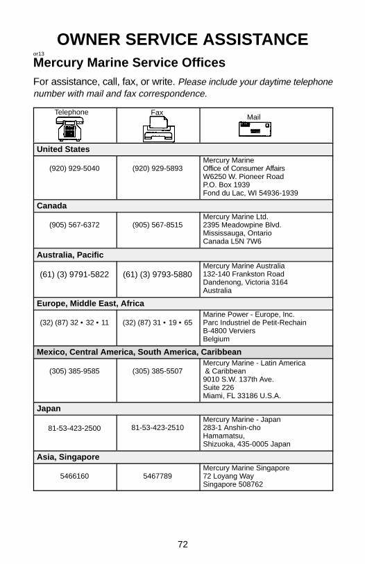
72
OWNER SERVICE ASSISTANCEor13
Mercury Marine Service OfficesFor assistance, call, fax, or write. Please include your daytime telephonenumber with mail and fax correspondence.
Telephone FaxMail
United States
(920) 929-5040 (920) 929-5893Mercury MarineOffice of Consumer AffairsW6250 W. Pioneer RoadP.O. Box 1939Fond du Lac, WI 54936-1939
Canada
(905) 567-6372 (905) 567-8515Mercury Marine Ltd.2395 Meadowpine Blvd.Mississauga, OntarioCanada L5N 7W6
Australia, Pacific
(61) (3) 9791-5822 (61) (3) 9793-5880Mercury Marine Australia132-140 Frankston RoadDandenong, Victoria 3164Australia
Europe, Middle East, Africa
(32) (87) 32 • 32 • 11 (32) (87) 31 • 19 • 65Marine Power - Europe, Inc.Parc Industriel de Petit-RechainB-4800 VerviersBelgium
Mexico, Central America, South America, Caribbean
(305) 385-9585 (305) 385-5507Mercury Marine - Latin America & Caribbean9010 S.W. 137th Ave.Suite 226Miami, FL 33186 U.S.A.
Japan
81-53-423-2500 81-53-423-2510Mercury Marine - Japan283-1 Anshin-choHamamatsu,Shizuoka, 435-0005 Japan
Asia, Singapore
5466160 5467789Mercury Marine Singapore72 Loyang WaySingapore 508762

73
MAINTENANCE LOGoka1
Maintenance LogRecord here all maintenance performed on your outboard. Be sureto save all work orders and receipts.
Date Maintenance Performed EngineHours

74
MAINTENANCE LOGDate Maintenance Performed Engine
Hours