Embed Size (px)
Citation preview

Executive Summary
This report entails all aspects of the Vandalay Industries Catapult. The Vandalay
catapult integrates cost efficiency, reliability, safety and practicality into one product.
Many hours were spent designing, testing and refining the final product. For any catapult
design, Vandalay Industries is capable of designing catapults for of means or methods.
During the prototype competition, the results spoke for themselves. This catapult is the
best overall catapult.
1

Table of Contents
Page 1: Executive Summary
Page 2: Table of Contents
Page 3: Introduction
Page 4-7: Methodology Brainstorming Catapult Construction Design Testing Graph Prototype Pictures Page 8-12: Results and Discussion Target Force Trajectory Trigger Page 13-17: Problems Addressed Prototype Design Changes
Final Product Design Changes Final Design Pictures Page 18: AutoCAD Drawing of Final Design Page 19: Conclusion
2

Introduction
The purpose of creating this project was to work as a team to create a catapult that
would consistently hit a target standing three meters away and has it perform superior in
every aspect over other companies’ catapults. Since Vandalay Industries prides itself on
designing the absolute best products, this was not a problem.
A catapult design was to be created and built. This catapult, however, had to meet
certain specifications. The criteria are as follows:
• The catapult cannot have an area exceeding 1.5 cubic feet • The catapult must hit the target
• The catapult must fire a golf ball
• The catapult must have a triggering mechanism
After being built, the prototype would then be tested with competing companies’
prototypes. After the testing, improvements were to be made to the prototype and a final
product was to be created. The final product would then test, examined, and graded.
This report discusses in detail the methods and logic used to design this catapult,
the VIC.
3

Methodology
Brainstorming To come up with an idea for the catapult each member of the team drew a design.
The drawings were then discussed openly. The pros and cons of each design were
examined. The best aspects were taken from each design and the prototype design was
created. The preliminary AutoCAD sketch of the prototype drawing is shown below.
Figure 1 This design is the product of the fusion of all of the best ideas Vandalay Industries
has to offer. The simplicity of this design is by far the catapult’s best feature.
4

Catapult Construction
The most logical choice for the material to be used was wood. Wood is cheap and
is easily manipulated. A combination of 2x4’s and screws were used to hold the wood
together. Plywood was used for the bottom surface to support the bricks used to hold the
catapult in position. A jet-ski handpole spring (for further information on the spring see
Force) was used to give maximum force to launch the golf ball. A bolt was inserted
through the coil of the spring to hold the spring in place. A heavy-duty door hinge was
implemented to allow our throwing to move. A gate latch was used to secure the
catapult. Everything that was used in the making of this catapult was found from scraps.
Since the materials weren’t directly purchased, the overall cost had to be estimated. The
overall estimated cost of the project was found to be about twenty dollars.
The prototype was finished and tested. We tested the prototype thoroughly and
often. For each minor adjustment that was made, a test was done. These results are
shown on the next page in figure 2.
5

0
50
100
150
200
250
300
Tota
l Poi
nts
Ach
ieve
d
Prot
otyp
e 1
-
Cut
top
out o
fcu
p
-
Rem
ove
woo
dov
er s
prin
g
Prot
otyp
e 2
-
Adju
st u
p 2
slot
s
-
Adju
st u
p 1
slot
-
Adju
st to
left
-
Adju
st c
upsl
ight
ly
-
Adju
st d
own
1sl
ot
Prot
otyp
eC
ompe
titio
n
Fina
l Cat
apul
t
-
No
Adju
stm
ent
-
No
Adju
stm
ent
Design
Test of Our Designs
Trial 1 Trial 2 Trial 3
Figure 2
The final product was built over a period of one month. The Gnatt chart, shown below
(figure 3), shows in detail progress in relation to time. 10-17 10-22 10-24 10-29 10-31 11-5 11-7 11-12 11-14
Figure 3
Brainstorming Building Prototype Testing Prototype Competition Redesigning Presentation
As one can see from figure 2 and 3, the VIC needed very little redesigning. For
more information on the redesigning process see the problems addressed section.
6
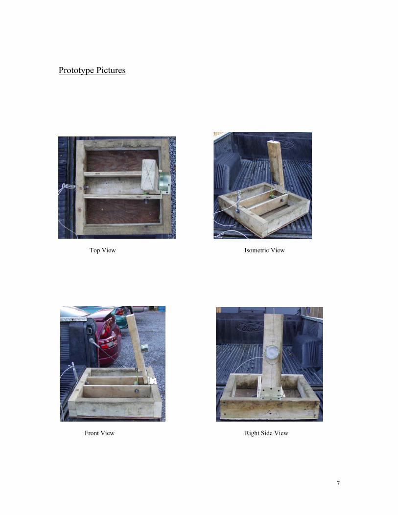
Prototype Pictures
Top View Isometric View
Front View Right Side View
7

Results and Discussion
Target
The target is the means in which our
performance for this project is
determined. The target itself has its
own specified dimensions which
were given. The dimensions stated
that the target would be located three
meters from the catapult’s launch
site. The bull’s eye would have a
diameter of three inches. The center of
the bull’s eye would be located twenty and one-half inches from the ground. The
catapult’s performance would be judged based on how close the ball hit in relation to the
bull’s eye. The point values decreased the further we hit from the bull’s eye. The values
were one hundred points for the bull’s eye, ninety for the next ring, eighty for the next,
and on down to zero points for not hitting anything. Each group also had one fault or
misfire they could commit and that score would be omitted. The best three scores are
added to determine each group’s catapult performance.
Figure 4
8
Force
The force used in the Vandalay Industries catapult comes from a Kawasaki Jet Ski
handpole spring. The purpose of the handpole spring is to lessen the amount of weight of
the handpole so that the rider will not get fatigued. The handpole spring is a torsion
spring rather than an extension or compression spring.
There are three types of springs, torsion, extension and compression. An
extension springs characteristics is that when extended or stretched out; its force causes it
to return to its original length. This type of spring is commonly used to close screen
doors. Sometimes they are placed at the end of a porch swing chain to lessen the amount
of stress on the swings mounting hooks. Extensions look very similar to compression
springs.
Compression springs are also a common spring used everyday. Compression
springs are compressed or squeezed than return to its original length. The springs are the
same typed used on a car’s suspension. These types of springs can support very heavy or
light loads. Compression springs are also used ballpoint pens. The forces capable of
either an extension or compression spring depend all on the spring constant. This
constant is measured in lbs per in or kg per mm. Also this constant varies with its size of
coils, number of coils, and spacing between the coils. Although extension and
compression are similar, torsion springs are different.
A torsion spring is twisted or wound up to produce the force. A torsion spring is
used on the cover of a floppy diskette to keep it closed when not opened by the computer
drive. This type of spring was ideal for a catapult since the firing arm of the catapult
rotates about a hinged point. All three types of springs work because of the elasticity
9

properties of the metal, which is used. All metals
and materials have elastic and plastic properties;
this is how springs are able to work.
Because of the small size and great force
of a torsion spring, this was the best choice for this
project. Pictured to the right in figure 5 the VIC’s
torsion spring is shown.
Figure 5
Trajectory When any object is shot or fired into the air, it is subjected to the forces that fired
it and other forces such as air friction and gravity. The gravitational constant is 9.806
meters per second squared or 32.174 feet per second squared. The force of gravity causes
the object or projectile, to follow a parabolic path. This is path that is in the shape of an
arc, as shown in figure 6. Using the laws and formulas from physics, many things can be
determined about the path of the projectile.
The projectile is a vector force at a certain angle. When this vector is broken
down into its horizontal and vertical components, the distance and height of the projectile
can be determined. When finding the distance, the x version of the projectile motion
formula is used. The horizontal force component and the time are needed to find out how
far the projectile went. Likewise if the any two of the three variables are know, the other
10

can be found. This is also true for the vertical time, force and distances. When finding
the maximum height of the projectile from the ground, the vertical force will be zero
since the projectile is not moving upwards anymore.
With physics, any specific point or target can be calculated out to find the setting
of the catapult. So if the distance in both the horizontal and vertical directions is given,
the catapult can be set up to hit this target. However, the force of the catapult and the
angle at which the projectile is launched must be known.
Figure 6
Vandalay Industries’ catapult was constructed with a knowledge of
Physics and projectile motion. No specific calculations were made
concerning force, time, and distance. Instead a trial and error method was
implied to get the correct trajectory of the golf ball. Although a flat arc, the
flight path of is ideal for the target at which it is firing at. The flatter arc
provides shorter flights and reduced air friction. If a taller target must be hit,
the ball holder is simply moved farther up the lever. With the consistent
launching position from the trigger, the catapult’s trajectory is constant.
11

Trigger The initial firing system was changed after the prototype competition. It
consisted of a turnbuckle bolted to the catapult, a string, and a cut off nail. The nail was
inserted into the lever and the head was cut off. This was a
safety concern because someone may have been injured by the
sharp nail. The string was attached to the turnbuckle. The lever
was compressed and the eye bolt hooked the nail. Then the
turnbuckle was next pulled away from and off of the nail. The
nail which is part of the lever went through the motion of the
lever. This is where the safety concern came into effect.
Pictured in the bottom right in figure 8 is the new and improved trigger for safety, the gate latch.
Figure 7
Concerned with s
trigger was changed to a
This type of latch provid
holding and releasing the
added feature is the oppo
a hole in the catapult. T
catapult in loaded positio
up the trigger so that it c
Pictured in the upper left in figure 7 is the turnbuckle and nail design, the originaltrigger.
afety the nail and turnbuckle
Stanley products gate latch.
ed a safe and secure way
catapult lever. Another
rtunity to place a lock through
his absolutely locks the
n. Another option it to lock
an not latched at all. Also the Figure 8
12

trigger had to be slightly modified for use. There was a metal edge that had to be filed
off to allow smother and easy release. With these changes, the Vandalay Industries is
now safer and more accurate. A consistent launching point is now possible. Additionally
no misfires or sharp objects are present to injure anyone.
13

Problems Addressed
Original Design Changes
During the building process of the prototype, there were only two major changes
to the design of the prototype. One was the removal of the top portion of the projectile
holder to make it hit the target higher. The other was a cut in the lever board to allow the
spring to reach a fuller potential.
The removal of the top portion of the holder, a cup, allowed the projectile to have
a higher trajectory. With the original cup, the projectile would stay against the top
portion all the way through the acceleration process and end up hitting the ground before
it reached the target. After the removal, the projectile wouldn’t be held down anymore
and therefore, hit the target higher. However, this height was still too low to hit the bull’s
eye. This led to needing more power from the spring.
The power of the spring was not fully harnessed. There was a piece of the lever
jamming against the base of the catapult stopping it from being pushed farther down.
Removing this piece allowed the spring to be compressed further and hence, more power
was acquired. After a small amount of fine tuning with the adjustments between the lever
and the cup, the catapult was accurate and precise.
14

Final Product Design Changes
After the prototype competition, a few more changes were made to improve upon
the prototype. These changes made the final product safer, lighter, and very consumer
friendly. First of all the hinge was changed to a longer, sturdier one. The lever board was
made full again as recessing the spring made this cut unnecessary. Holes were made for
the pivot point of the spring making adjustments readily available. The final change was
to make the trigger a safer.
In the middle of the prototype competition, we observed a small crack forming
around the screws in the hinge. This was an unacceptable risk as the lever could possibly
crack off. The problem was rectified by adding a longer hinge with longer screws that
would distribute the force evener. This also led to the changing of the old lever.
A new lever was added to correct a cut that was made in the prototype. This cut
is now unnecessary because the spring is recessed more and adjustable. This lever is now
much stronger and therefore safer.
The spring is now adjustable. Five pivot holes were added at a lower level to
accept a full lever. This made direct adjustments to the force possible. Each of these
adjustments added six inches up if moved towards the front one hole and moved six
inches down if moved back one hole. These changes applied for all the adjustable holes.
The final change to the prototype to complete the final product was made to the
release trigger. The original trigger was sharp and had the small possibility of pinching a
finger during a release. This old trigger also had no way to lock the lever down which
was thought to be another danger. The new trigger is smoothed over and has no sharp
15
edges. The actual catch has a hole so that if a lock is put through it, the catapult is totally
unusable.
After completion of all of these modifications, we have ended up with a safe,
secure, and accurate catapult.
16

Final Design Pictures
Top View Isometric View
Front View Right Side View
17

AutoCAD Final Drawing
18
Conclusions
The overall design of the Vandalay Industries catapult is relatively simple. It is a
very cost efficient and effective design. Also the ease adjustability makes it the very
adaptable to different situations. The added benefits of a powerful spring enable the
catapult to hit targets much farther than the specified three meters. Other designs are not
capable of this task. Add to the fact the catapult’s accuracy and precision. The Vandalay
Industries catapult is the logical choice for anyone’s catapult needs.
19
![Food security and nutrition: building a global narrative ... · EXECUTIVE SUMMARY EXECUTIVE SUMMARY EXECUTIVE SUMMARY EXECUTIVE SUMMAR Y [ 2 ] This document contains the Summary and](https://img.pdfslide.us/doc/110x75/5ff5433612d22125fb06e6b5/food-security-and-nutrition-building-a-global-narrative-executive-summary-executive.jpg)