Embed Size (px)
Citation preview
91 SPS 341 Appendix ASAFETY AND PROFESSIONAL SERVICES
Published under s. 35.93, Wis. Stats., by the Legislative Reference Bureau.
Published under s. 35.93, Stats. Updated on the first day of each month. Entire code is always current. The Register date on each page
is the date the chapter was last published. Register May 2012 No. 677
Chapter SPS 341
APPENDIX A
EXCERPTS FROM: ASME BOILER AND PRESSURE VESSEL CODE
SECTION I − POWER BOILERS
2010 EDITIONINTRODUCTION
This Code covers rules for construction of power boilers1,electric boilers2, miniature boilers3, high−temperature waterboilers4, heat recovery steam generators5, and certain fired pres-sure vessels6 to be used in stationary service and includes thosepower boilers used in locomotive, portable, and traction service.Reference to a paragraph includes all the subparagraphs andsubdivisions under that paragraph.
1 Power boiler − a boiler in which steam or other vapor is generated at a pres-sure of more than 15 psi (100 kPa) for use external to itself.
2 Electric boiler − a power boiler or a high−temperature water boiler in whichthe source of heat is electricity.
3 Miniature boiler − a power boiler or a high−temperature water boiler inwhich the limits specified in PMB−2 are not exceeded.
4 High−temperature water boiler − a water boiler intended for operation atpressures in excess of 160 psi (1.1 MPa) and/or temperatures in excess of250°F (120°C).
5 Heat recovery steam generator (HRSG) − a boiler that has as its principalsource of thermal energy a hot gas steam having high−ramp rates and tem-peratures such as the exhaust of a gas turbine.
6 Fired pressure vessel − reheaters, isolable superheaters, and nonintegral sep-arately fired superheaters.
The Code does not contain rules to cover all details of designand construction. Where complete details are not given, it isintended that the manufacturer, subject to the acceptance of theAuthorized Inspector, shall provide details of design and con-struction which will be as safe as otherwise provided by the rulesin the Code.
The scope of jurisdiction of Section I applies to the boilerproper and to the boiler external piping.
Superheaters, economizers, and other pressure parts con-nected directly to the boiler without intervening valves shall beconsidered as parts of the boiler proper, and their constructionshall conform to Section I rules.
Boiler external piping shall be considered as that pipingwhich begins where the boiler proper or isolable superheater, orisolable economizer terminates at:
(a) the first circumferential joint for welding end connec-tions; or
(b) the face of the first flange in bolted flanged connections;or
(c) the first threaded joint in that type of connection; andwhich extends up to and including the valve or valves requiredby this Code.
ASME Code Certification (including Data Forms and CodeSymbol Stamping), and/or inspection by the Authorized Inspec-tor,when required by this Code, is required for the boiler properand the boiler external piping.
Construction rules for materials, design, fabrication, installa-tion, and testing of the boiler external piping are contained inASME B3l.l, Power Piping. Piping beyond the valve or valvesrequired by Section I is not within the scope of Section I, and itis not the intent that the Code Symbol Stamp be applied to suchpiping or any other piping.
The material for forced−circulation boilers, boilers with nofixed steam and water line, and high−temperature water boilers
shall conform to the requirements of the Code. All other require-ments shall also be met except where they relate to special fea-tures of construction made necessary in boilers of these types,and to accessories that are manifestly not needed or used in con-nection with such boilers, such as water gages and water col-umns.
Reheaters receiving steam which has passed through part ofa turbine or other prime mover and separately fired steam super-heaters which are not integral with the boiler are considered firedpressure vessels and their construction shall comply with Coderequirements for superheaters, including safety devices. Pipingbetween the reheater connections and the turbine or other primemover is not within the scope of the Code. Steam piping to theinlet connections and from the outlet connections of nonintegralseparately fired superheaters is not within the scope of the Code.
A pressure vessel in which steam is generated by the applica-tion of heat resulting from the combustion of fuel (solid, liquid,or gaseous) shall be classed as a fired steam boiler.
Unfired pressure vessels in which steam is generated shall beclassed as unfired steam boilers with the following exceptions:
(a) vessels known as evaporators or heat exchangers
(b) vessels in which steam is generated by the use of heatresulting from operation of a processing system containing anumber of pressure vessels such as used in the manufacture ofchemical and petroleum products
Unfired steam boilers shall be constructed under the provi-sions of Section I or Section VIII.
Expansion tanks connected to high−temperature water boil-ers without intervening valves shall be constructed to therequirements of Section I or Section VIII.
A pressure vessel in which an organic fluid is vaporized bythe application of heat resulting from the combustion of fuel(solid, liquid, or gaseous) shall be constructed under the provi-sions of Section I. Vessels in which vapor is generated incidentalto the operation of a processing system, containing a number ofpressure vessels such as used in chemical and petroleum manu-facture, are not covered by the rules of Section I.
PART PGGENERAL REQUIREMENTS FOR ALL
METHODS OF CONSTRUCTIONGENERAL
PG−1 SCOPE
The requirements of Part PG apply to power boilers and highpressure, high−temperature water boilers and to parts and appur-tenances thereto and shall be used in conjunction with the spe-cific requirements in the applicable Parts of this Section that per-tain to the methods of construction used.
PG−2 SERVICE LIMITATIONS
PG−2.1 The rules of this Section are applicable to the follow-ing services:
(a) boilers in which steam or other vapor is generated at apressure of more than 15 psig (100kPa)

92SPS 341 Appendix A WISCONSIN ADMINISTRATIVE CODE
Published under s. 35.93, Wis. Stats., by the Legislative Reference Bureau.
Published under s. 35.93, Stats. Updated on the first day of each month. Entire code is always current. The Register date on each
page is the date the chapter was last published.Register Mary 2012 No. 677
(b) high−temperature water boilers intended for operation atpressures exceeding 160 psig (1.1 MPa) and/or temperaturesexceeding 250�F (120�C)
PG−2.2 For services below those specified in PG−2.1 it isintended that rules of Section IV apply; however, boilers forsuch services may be constructed and stamped in accordancewith this Section provided all applicable requirements are met.
PG−2.3 Coil−type hot water boilers where the water canflash into steam when released directly to the atmospherethrough a manually operated nozzle may be exempted from therules of this Section provided the following conditions are met:
(a) There is no drum, header, or other steam space.
(b) No steam is generated within the coil.
(c) Tubing outside diameter does not exceed 1 in. (25 mm).
(d) Pipe size does not exceed NPS ¾ (DN 20).
(e) Nominal water capacity does not exceed 6 gal (23 L).
(f) Water temperature does not exceed 350�F (175�C).
(g) Adequate safety relief valves and controls are provided.
PG−3 REFERENCED STANDARDS
Specific editions of standards referenced in this Section areshown in A−360.
PG−4 UNITS
Either U.S. Customary units or SI units may be used for com-pliance with all requirements of this edition, but one system shallbe used consistently throughout for all phases of construction.
Either the U.S. Customary units or SI units that are listed inMandatory Appendix II are identified in the text, or are identi-fied in the nomenclature for equations, shall be used consistentlyfor all phases of construction (e.g., materials, design, fabrica-tion, and reports). Since values in the two systems are not exactequivalents, each system shall be used independently of theother without mixing U.S. Customary units and SI units.
When SI units are selected, U.S. Customary values in refer-enced specifications that do not contain SI units shall be con-verted to SI values to at least three significant figures for use incalculations and other aspects of construction.
MATERIALS
PG−5 GENERAL
PG−5.1 Except as otherwise permitted in PG−8.2, PG−8.3,PG−10, and PG−11, material subject to stress due to pressureshall conform to one of the specifications given in Section II andshall be limited to those that are listed in the Tables of SectionII, Part D. The manufacturer shall ensure that the correct mate-rial has been received and is properly identified before proceed-ing with construction (see A−302.4). Materials shall not be usedat temperatures above those for which stress values are limited,for Section I construction, in the Tables of Section II, Part D.Specific additional requirements described in PG−5 throughPG−13 shall be met as applicable.
PG−5.2 Material covered by specifications in Section II isnot restricted as to the method of production unless so stated inthe specification, and as long as the product complies with therequirements of the specification.
PG−5.3 If, in the development of the art of boiler construc-tion, it is desired to use materials other than those hereindescribed, data should be submitted to the Boiler and PressureVessel Committee in accordance with the requirements ofAppendix 5 of Section II, Part D. Material not completely iden-tified with any approved Code specifications may be used in theconstruction of boilers under the conditions outlined in PG−10.
PG−5.4 Size Limits and Tolerances
PG−5.4.1 Materials outside the limits of size or thicknessgiven in the title or scope clause of any specification in SectionII may be used if the material is in compliance with the otherrequirements of the specification, and no similar limitation isgiven in the rules for construction.
PG−5.4.2 Pipe having a tolerance of ±1% on either the O.D.or the I.D. rather than the tolerance specified in the materialspecification, may be used, provided the material complies withall other requirements of the specifications. When used underexternal pressure, such pipe shall be limited to a maximum of 24in. (600 mm) in diameter. The pipe shall include the designation1% O.D. or 1% I.D., as appropriate, in any required documenta-tion and marking of the material.
PG−5.5 The use of austenitic alloy steel is permitted forboiler pressure parts that are steam touched in normal operation.Except as specifically provided in PG−9.1.1, PG−12, andPEB−5.3, the use of such austenitic alloys for boiler pressureparts that are water wetted in normal service is prohibited.7
7 Austenitic alloys are susceptible to intergranular corrosion and stress corro-
sion cracking when used in boiler applications in water wetted service. Fac-
tors that affect the sensitivity to these metallurgical phenomena are applied
or residual stress and water chemistry. Susceptibility to attack is usually
enhanced by using the material in a stressed condition with a concentration
of corrosive agents (e.g., chlorides, caustic, or reduced sulfur species). For
successful operation in water environments, residual and applied stresses
must be minimized and careful attention must be paid to continuous control
of water chemistry.
PG−5.6 P−No. 15E, Group 1 Materials
PG−5.6.1 If during any phase of manufacturing or erectionany portion of the component that does not contain a weld isheated to a temperature greater than 1,470°F (800°C), one of thefollowing actions shall be performed:
(a) The component shall be reaustenitized and retempered inits entirety in accordance with the specification requirements.
(b) That portion of the component heated above 1,470°F(800°C), including the heat−affected zone created by the localheating, must be replaced or must be removed, reaustenitized,and retempered in accordance with the specification require-ments and then replaced in the component.
(c) If the allowable stress values to be used are less than orequal to those provided in Table 1A of Section II, Part D forGrade 9 (e.g., SA−213 T9, SA−335 P9, or equivalent productspecifications) at the design temperature, then the requirementsstated above may be waived, provided that the portion of thecomponent heated above 1,470°F (800°C) is retempered inaccordance with the specification requirements. The use of thisprovision shall be noted on the Manufacturer’s Data Report.
PG−5.6.2 If during any phase of manufacturing or erectionof the component, any portion that does contain a weld is heatedabove 1,425°F (775°C), then the requirements of Notes (3) and(4) of Table PW−39 for P−No. 15E, Group 1 Materials, shallapply for reheat treatment.
PG−6 PLATE
PG−6.1 Steel plates for any part of a boiler subject to pres-sure, whether or not exposed to the fire or products of combus-tion shall be of pressure vessel quality in accordance with oneof the following specifications:
SA−202 Pressure Vessel Plates, Alloy Steel, Chromium−Manganese−Silicon
SA−204 Pressure Vessel Plates, Alloy Steel, Molybdenum
SA−240 (Type 405 only) Pressure Vessel Plates, Alloy Steel(Ferritic Stainless), Chromium

93 SPS 341 Appendix ASAFETY AND PROFESSIONAL SERVICES
Published under s. 35.93, Wis. Stats., by the Legislative Reference Bureau.
Published under s. 35.93, Stats. Updated on the first day of each month. Entire code is always current. The Register date on each page
is the date the chapter was last published. Register May 2012 No. 677
SA−285 Pressure Vessel Plates, Carbon Steel, Low−andIntermediate−Tensile Strength
SA−299 Pressure Vessel Plates, Carbon Steel, Manganese−Silicon
SA−302 Pressure Vessel Plates, Alloy Steel, Manganese−Molybdenum and Manganese−Molybdenum−Nickel
SA−387 Pressure Vessel Plates, Alloy Steel, Chromium−Mo-lybdenum
SA−515 Pressure Vessel Plates, Carbon Steel, for Intermedi-ate− and Higher−Temperature Service
SA−516 Pressure Vessel Plates, Carbon Steel, for Moderate−and Lower−Temperature Service
SA/AS 1548 Steel Plates for Pressure Equipment
SA/EN−10028−2 Flat Products Made of Steels for PressurePurposes
SA/JIS G3118 Carbon Steel Plates for Pressure Vessels forIntermediate and Moderate Temperature Service
PG−55 SUPPORTS AND ATTACHMENT LUGS
PG−55.1 Lugs or hangers when used to support a boiler ofany type shall be properly fitted to the surfaces to which they areattached.
PG−55.2 Lugs, hangers, or brackets may be attached byfusion welding provided the welding meets the requirements ofPart PW, including stress relieving but omitting volumetricexamination and provided they are attached by full penetrationwelds, combination groove and fillet welds, or by fillet weldsalong the entire periphery or contact edges. Some acceptableforms of welds for lugs, hangers, or brackets are shown in Fig.PW−16.2. The materials for lugs, hangers, or brackets are notlimited to those listed in Tables 1A and 1B of Section II, Part D,but shall be of weldable quality. The allowable load on the filletwelds shall equal the product of the weld area based on mini-mum leg dimension, the allowable stress value in tension of thematerial being welded, and the factor 0.55. When using weldedpipe, the stress values given in Table 1A of Section II, Part D,may be increased to that of the basic material by eliminating thestated weld efficiencies.
94SPS 341 Appendix A WISCONSIN ADMINISTRATIVE CODE
Published under s. 35.93, Wis. Stats., by the Legislative Reference Bureau.
Published under s. 35.93, Stats. Updated on the first day of each month. Entire code is always current. The Register date on each
page is the date the chapter was last published.Register Mary 2012 No. 677
95 SPS 341 Appendix ASAFETY AND PROFESSIONAL SERVICES
Published under s. 35.93, Wis. Stats., by the Legislative Reference Bureau.
Published under s. 35.93, Stats. Updated on the first day of each month. Entire code is always current. The Register date on each page
is the date the chapter was last published. Register May 2012 No. 677

96SPS 341 Appendix A WISCONSIN ADMINISTRATIVE CODE
Published under s. 35.93, Wis. Stats., by the Legislative Reference Bureau.
Published under s. 35.93, Stats. Updated on the first day of each month. Entire code is always current. The Register date on each
page is the date the chapter was last published.Register Mary 2012 No. 677

97 SPS 341 Appendix ASAFETY AND PROFESSIONAL SERVICES
Published under s. 35.93, Wis. Stats., by the Legislative Reference Bureau.
Published under s. 35.93, Stats. Updated on the first day of each month. Entire code is always current. The Register date on each page
is the date the chapter was last published. Register May 2012 No. 677
98SPS 341 Appendix A WISCONSIN ADMINISTRATIVE CODE
Published under s. 35.93, Wis. Stats., by the Legislative Reference Bureau.
Published under s. 35.93, Stats. Updated on the first day of each month. Entire code is always current. The Register date on each
page is the date the chapter was last published.Register Mary 2012 No. 677
99 SPS 341 Appendix ASAFETY AND PROFESSIONAL SERVICES
Published under s. 35.93, Wis. Stats., by the Legislative Reference Bureau.
Published under s. 35.93, Stats. Updated on the first day of each month. Entire code is always current. The Register date on each page
is the date the chapter was last published. Register May 2012 No. 677
BOILER EXTERNAL PIPING AND BOILERPROPER CONNECTIONS
PG−58 OUTLETS AND EXTERNAL PIPING
PG−58.1 General. The rules of this subparagraph apply tothe boiler external piping as defined in the Preamble.
PG−58.2 Boiler External Piping Connections to Boilers.All boiler external piping connected to a boiler for any purposeshall be attached to one of the types of joints listed inPG−59.1.1.1, PG−59.1.1.2, and PG−59.1.1.3.
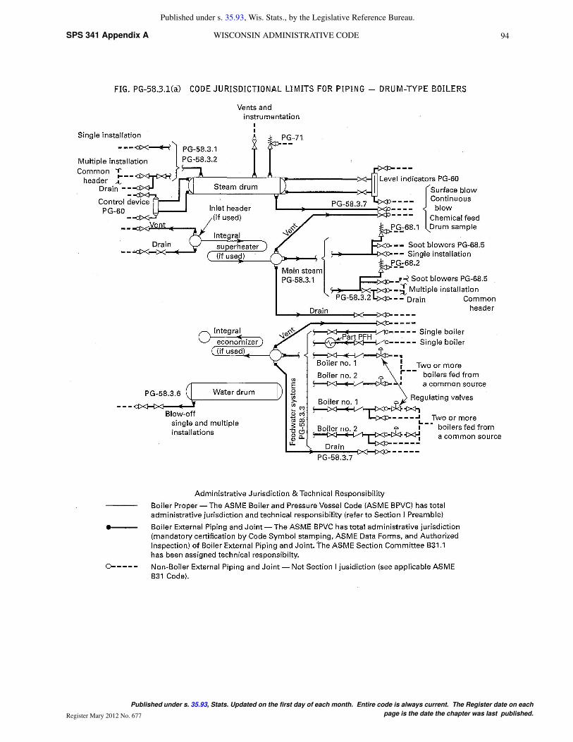
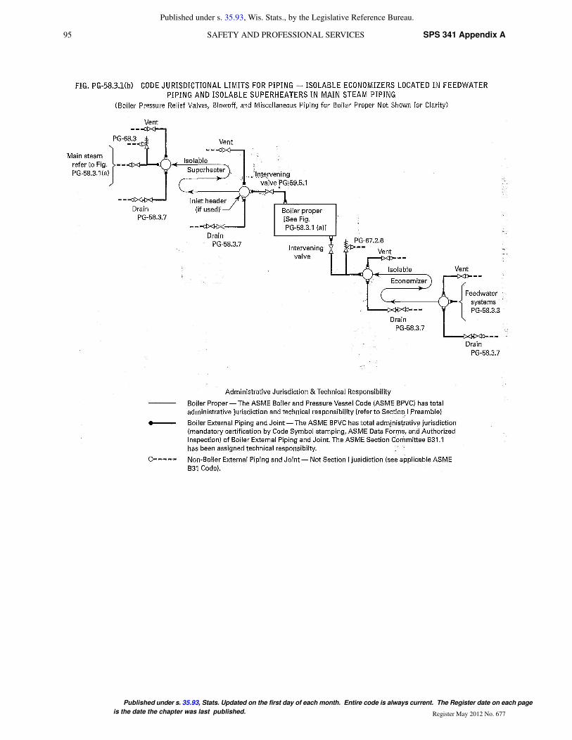
PG−58.3 Boiler External Piping. The following defines theCode Jurisdictional Limits of the boiler external piping systems,including general requirements, valves, and inspection. Thelimits are also shown in Figs. PG−58.3.1 and PG−58.3.2. Thematerials, design, fabrication, installation, and testing shall be inaccordance with ASME B31.1, Power Piping.
PG−58.3.1. The steam piping connected to the boiler drumor to the superheater outlet header shall extend up to and includ-ing the first stop valve in each connection, except as required byPG−58.3.2. In the case of a single boiler and prime mover instal-lation, the stop valve required herein may be omitted providedthe prime mover throttle valve is equipped with an indicator toshow whether the valve is open or closed and is designed to with-stand the required hydrostatic pressure test of the boiler.
For an isolable or separately fired superheater which dis-charges steam directly to a process stream, the stop valverequired by this paragraph and the safety valve(s) required byPG−68 may be omitted provided the following conditions aresatisfied:
(a) The boiler is a drum−type boiler in a single−boiler instal-lation.
(b) The steam discharge passes through the process streamto the atmosphere with no intervening valves.
(c) The system shall be designed so that the process streamthrough which the steam discharge passes cannot be obstructedin such a way as to cause the pressure in the superheater toexceed that permitted by PG−67.2, with maximum steam flowfrom the boiler to the superheater. Flow and pressure calcula-tions demonstrating that the superheater will not be overpressur-ized under any steam flow conditions shall be documented andmade available to the Inspector. These calculations shall be cer-tified by a Professional Engineer experienced in the mechanicaldesign of power plants.
(d) There is no valve on the discharge side of the superheater.
(e) Section I jurisdiction shall include the pressure partsbetween the superheater inlet and the outlet at:
(1) the first circumferential joint for welding end connec-tions; or
(2) the face of the first flange in bolted flange connections;or
(3) the first threaded joint in that type of connection.
PG−58.3.2 When two or more boilers are connected to acommon steam header, or when a single boiler is connected toa header having another steam source (e.g., a turbine extractionline), the connection from each boiler having a manhole openingshall be fitted with two stop valves having an ample free−blowdrain between them. The boiler external piping includes all pip-ing from the boiler proper up to and including the second stopvalve and the free−blow drain valve.
PG−58.3.3 The feedwater piping for all boilers, except high−temperature water boilers and forced−flow steam generatorscomplying with PG−58.3.5, shall extend through the requiredstop valve and up to and including the check valve except asrequired by PG−58.3.4. On a single boiler−turbine unit installa-
tion the boiler feed shutoff valve may be located upstream fromthe boiler feed check valve.
If a feedwater heater or heaters meeting the requirements ofPart PFH are installed between the required stop valve and theboiler, and are fitted with isolation and bypass valves, provisionsmust be made to prevent the feedwater pressure from exceedingthe maximum allowable working pressure of the piping or feed-water heater, whichever is less. Control and interlock systemsare permitted in order to prevent overpressure.
PG−58.3.4 When two or more boilers are fed from a com-mon source, the piping shall be up to and including a globe orregulating valve located between the check valve required inPG−58.3.3 and the source of supply. If the regulating valve isequipped with an isolation valve and a bypass valve, the pipingshall be up to and including both the isolation valve downstreamfrom the regulating valve and the shutoff valve in the bypass.
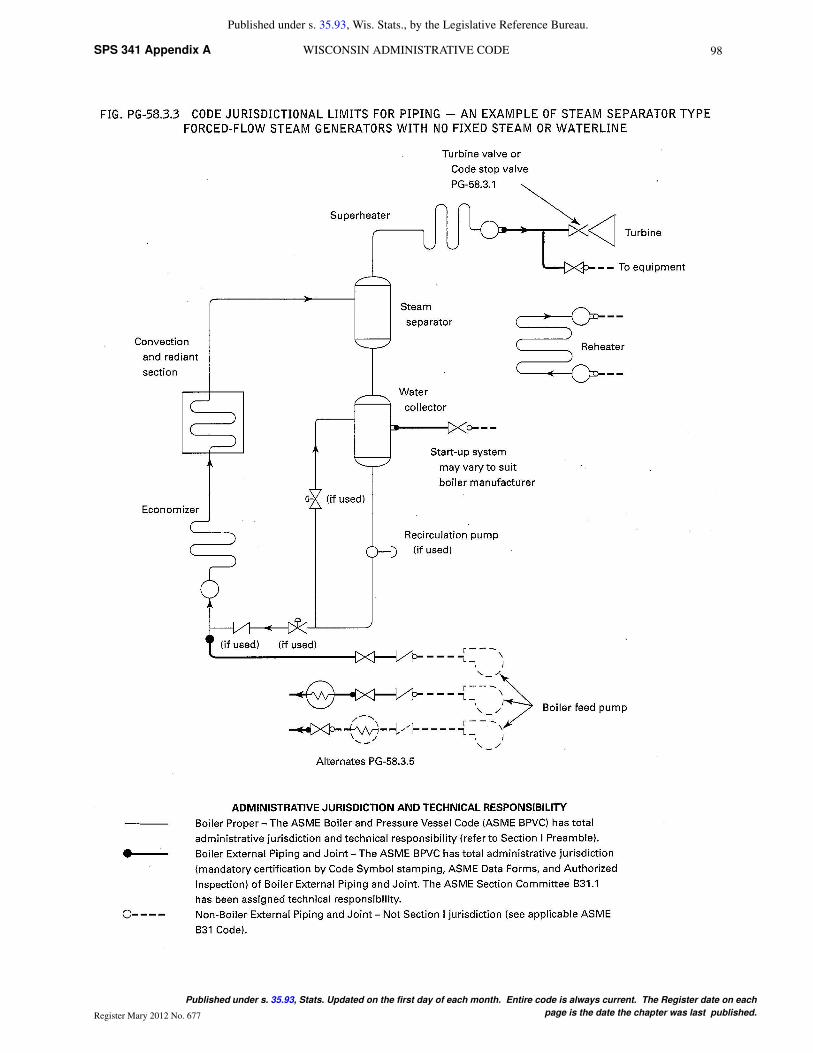
PG−58.3.5 The feedwater piping for a forced−flow steamgenerator with no fixed steam and waterline may terminate upto and including the stop valve near the boiler and omitting thecheck valve near the boiler, provided that a check valve havinga pressure rating no less than the boiler inlet design pressure isinstalled at the discharge of the boiler feed pump or elsewherein the feedline between the feed pump and the feed stop valve.If the feedwater heater(s) is fitted with isolation and bypassvalves, the applicable requirements of PG−58.3.3 must be met.
PG−58.3.6 The blowoff piping for all boilers, except forced−flow steam generators with no fixed steam and waterline, high−temperature water boilers, and those used for traction and/orportable purposes, when the maximum allowable working pres-sure exceeds 100 psi (700kPa) shall extend through and includ-ing the second valve. The blowoff piping for all traction and/orportable boilers and for forced circulation and electric boilershaving a normal water content not exceeding 100 gal (380 L) arerequired to extend through only one valve.
PG−58.3.7 The miscellaneous piping shall include the pip-ing for such items as drains, vents, surface−blow−off, steam andwater piping for water columns, gage glasses and pressuregages, and the recirculation return line for a high−temperaturewater boiler. When a drain is not intended for blowoff purposes(when the boiler is under pressure) a single valve is acceptable,otherwise two valves in series are required except as permittedby PG−58.3.6.
PG−58.3.8 Welded piping in PG−58.3.1, PG−58.3.2,PG−58.3.3, PG−58.3.4, PG−58.3.5, PG−58.3.6, and PG−58.3.7is also subject to the requirements of PG−104 for proper Codecertification.
100SPS 341 Appendix A WISCONSIN ADMINISTRATIVE CODE
Published under s. 35.93, Wis. Stats., by the Legislative Reference Bureau.
Published under s. 35.93, Stats. Updated on the first day of each month. Entire code is always current. The Register date on each
page is the date the chapter was last published.Register Mary 2012 No. 677
PG−59 APPLICATION REQUIREMENTS FOR THEBOILER PROPER
PG−59.1 Common to Steam, Feedwater, Blowoff, andDrain Systems
PG−59.1.1 Outlets of a boiler to which piping is to beattached for any purpose, and which piping comes within theCode requirements, shall meet the requirements of PG−39 andshall be:
PG−59.1.1.1 A tapped opening.
PG−59.1.1.2 Bolted flanged joints including those of the VanStone type.
PG−59.1.1.3 Welding ends of the butt or socket weldingtype.
PG−59.1.1.4 Piping within the boiler proper may beexpanded into grooved holes, seal welded if desired. Blowoffpiping of firetube boilers shall be attached by threading into atapped opening with a threaded fitting or valve at the other endif exposed to products of combustion, or by PG−59.1.1.1 orPG−59.1.1.2 if not so exposed (see PFT−49).
PG−59.1.2 Steam Mains. Provisions shall be made for theexpansion and contraction of steam mains connected to boilers,by providing substantial anchorage at suitable points, so thatthere shall be no undue strain transmitted to the boiler. Steamreservoirs shall be used on steam mains when heavy pulsationsof the steam currents cause vibration of the boiler shell plates.
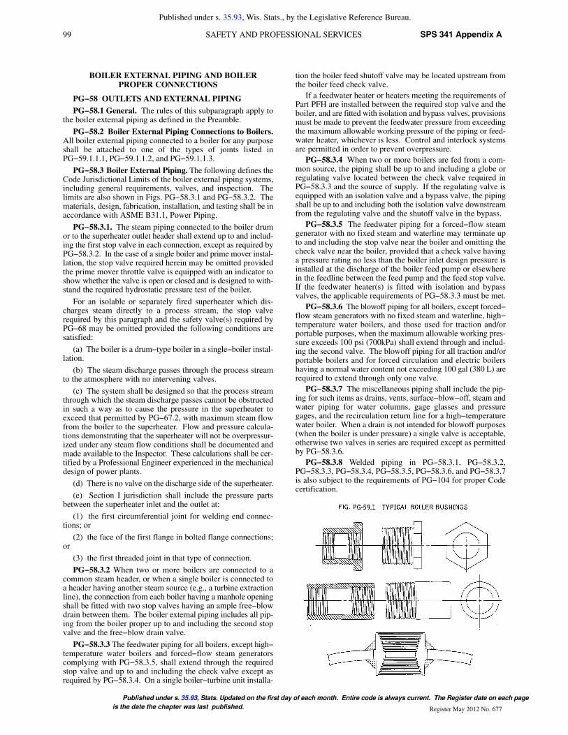
PG−59.1.3 Figure PG−59.1 illustrates a typical form of con-nection for use on boiler shells for passing through piping suchas feed, surface blowoff connections, etc., and which permits thepipes’ being threaded in solid from both sides in addition to thereinforcing of the opening of the shell. The pipes shall beattached as provided in PG−59.1.1. In these and other types ofboilers where both internal and external pipes making a continu-ous passage are employed, the boiler bushing or its equivalentshall be used.
PG−59.2 Requirements for Feedwater Connections. Thefeedwater shall be introduced into a boiler in such a manner thatthe water will not be discharged directly against surfacesexposed to gases of high temperature or to direct radiation fromthe fire. For pressures of 400 psi (3 MPa) or over, the feedwaterinlet through the drum shall be fitted with shields, sleeves, orother suitable means to reduce the effects of temperature differ-entials in the shell or head. Feedwater, other than condensatereturns as provided for in PG−59.3.6, shall not be introducedthrough the blowoff.
PG−59.3 Requirements for Blowoffs
PG−59.3.1 A blowoff as required herein is defined as a pipeconnection provided with valves located in the external pipingthrough which the water in the boiler may be blown out underpressure, excepting drains such as are used on water columns,gage glasses, or piping to feedwater regulators, etc., used for thepurpose of determining the operating condition of such equip-ment. Piping connections used primarily for continuous opera-tion, such as deconcentrators on continuous blowdown systems,are not classed as blowoffs but the pipe connections and all fit-tings up to and including the first shutoff valve shall be equal atleast to the pressure requirements for the lowest set pressure ofany safety valve on the boiler drum and with the correspondingsaturated−steam temperature.
PG−59.3.2 A surface blowoff connection shall not exceedNPS 2 ½ (DN 65), and the internal pipe and the terminal connec-tion for the external pipe, when used, shall form a continuouspassage, but with clearance between their ends and arranged sothat the removal of either will not disturb the other. A properlydesigned steel bushing, similar to or the equivalent of thoseshown in Fig. PG−59.1, or a flanged connection shall be used.
PG−59.3.3 Each boiler except forced−flow steam generatorswith no fixed steam and waterline and high−temperature waterboilers shall have a bottom blowoff outlet in direct connectionwith the lowest water space practicable for external piping con-forming to PG−58.3.6.
PG−59.3.4 All waterwalls and water screens that do notdrain back into the boiler, and all integral economizers, shall beequipped with outlet connections for a blowoff or drain line andconform to the requirements of PG−58.3.6 or PG−58.3.7.
PG−59.3.5 Except as permitted for miniature boilers in PartPMB, the minimum size of blowoff connections shall be NPS 1(DN 25), and the maximum size shall be NPS 2 ½ (DN 65),except that for boilers with 100 ft2 (9.3 m2) of heating surfaceor less, the minimum size of blowoff connections may be NPS¾ (DN 20).
PG−59.3.6 Condensate return connections of the same sizeor larger than the size herein specified may be used, and theblowoff may be connected to them. In such case the blowoffshall be so located that the connection may be completelydrained.
PG−59.3.7 A bottom blowoff pipe when exposed to directfurnace heat shall be protected by firebrick or other heat resist-ing material that is so arranged that the pipe may be inspected.
PG−59.3.8 An opening in the boiler setting for a blowoffpipe shall be arranged to provide free expansion and contraction.
PG−59.4 Requirements for Drains
PG−59.4.1 Ample drain connections shall be providedwhere required to permit complete drainage of all piping, super-heaters, waterwalls, water screens, integral economizers, high−temperature water boilers, and all other boiler components inwhich water may collect. Piping shall conform to the require-ments of PG−58.3.6 or PG−58.3.7.
PG−59.4.1.1 Each superheater shall be equipped with atleast one drain connection so located as to most effectively pro-vide for the proper operation of the apparatus.
PG−59.4.1.2 Each high−temperature water boiler shall havea bottom drain connection of at least NPS 1 (DN 25) in directconnection with the lowest water space practical for externalpiping conforming to PG−58.3.7.
PG−59.5 Requirements for Valves and Fittings. The fol-lowing requirements apply to the use of valves and fittings in theboiler proper.
PG−59.5.1 Steam Stop Valves
PG−59.5.1.1 If a shutoff valve is used between the boiler andits superheater, the safety valve capacity on the boiler shall com-ply with the requirements of PG−67.2 and PG−70, except as pro-vided for in PG−59.5.1.2, no credit being taken for the safetyvalve on the superheater, and the superheater must be equippedwith safety valve capacity as required by PG−68. A stop valveis not required at the inlet or the outlet of a reheater or separatelyfired superheater.
PG−59.5.1.2 When stop valves are installed in the water−steam flow path between any two sections of a forced–flowsteam generator with no fixed steam and waterline, the safetyvalves shall satisfy the requirements of PG−67.4.4.
DESIGN AND APPLICATION
PG−60 REQUIREMENTS FOR MISCELLANEOUSPIPE, VALVES, AND FITTINGS
Piping referred to in this paragraph shall be designed inaccordance with the applicable requirements of ASME B31.1.
PG−60.1 Water Level Indicators. All boilers having afixed water level (steam and water interface) shall have at leastone gage glass (a transparent device that permits visual deter-mination of the water level). Boilers not having a fixed waterlevel, such as forced−flow steam generators and high−tempera-
101 SPS 341 Appendix ASAFETY AND PROFESSIONAL SERVICES
Published under s. 35.93, Wis. Stats., by the Legislative Reference Bureau.
Published under s. 35.93, Stats. Updated on the first day of each month. Entire code is always current. The Register date on each page
is the date the chapter was last published. Register May 2012 No. 677
ture water boilers of the forced circulation type, are not requiredto have a gage glass. The lowest visible water level in a gageglass shall be at least 2 in. (50 mm) above the lowest permissiblewater level, as determined by the boiler Manufacturer. Elec-trode−type electric boilers are required to have only one gageglass, regardless of MAWP.
Gage glasses having multiple tubular sections shall have aminimum of 1 in. (25 mm) overlap of the sections in which thewater level may be visible. Segmented gage glasses, such asported or end−connected strip gages, shall be equipped to pro-vide obvious visual discrimination between water and vapor inthe individual sections.
PG−60.1.1 Boilers having a maximum allowable workingpressure exceeding 400 psi (3 MPa) shall have two gage glasses.Instead of one of the two required gage glasses, two independentremote water level indicators (two discrete systems that continu-ously measure, transmit, and display water level) may be pro-vided.
PG−60.1.1.1 When the water level in at least one gage glassis not readily visible to the operator in the area where controlactions are initiated, either a fiber optic cable (with no electricalmodification of the optical signal) or mirrors shall be providedto transfer the optical image of the water level to the control area.Alternatively, any combination of two of the following shall beprovided:
(a) an independent remote water level indicator
(b) an independent continuous transmission and display ofan image of the water level in a gage glass.
PG−60.1.1.2 When two independent remote water levelindicators are in reliable operation (continuously indicatingwater level), the one required gage glass may be shut off, butshall be maintained in the serviceable condition.
PG−60.1.1.3 The display of a remote water level indicatorshall have a clearly marked minimum water level reference atleast 2 in. (50 mm) above the lowest permissible water level, asdetermined by the Manufacturer.
PG−60.1.6 Each gage glass shall be fitted with a drain cockor valve having an unrestricted drain opening of not less than ¼in. (6 mm) diameter to facilitate cleaning. When the boilerMAWP exceeds 100 psi (700 kPa), the gage glass shall be fur-nished with a connection to install a valved drain to a point ofsafe discharge.
Each gage glass shall be equipped with a top and a bottomshutoff valve of such through−flow construction as to preventstoppage by deposits of sediments. If the bottom valve is morethan 7 ft (2 m) above the floor or platform from which it is oper-ated, the operating mechanism shall indicate by its positionwhether the valve is open or closed. The pressure—temperaturerating of valves, fittings, and piping shall be at least equal to theboiler MAWP and the corresponding saturated−steam tempera-ture.
Straight−run globe valves shall not be used on such connec-tions. Automatic shutoff valves, if permitted to be used, shallconform to the requirements given in A−18.
PG−60.2 Water Columns
PG−60.2.1 A water column shall be so mounted that it willbe correctly positioned, relative to the normal water level underoperating conditions.
PG−60.2.3 Each water column shall be furnished with a con-nection of at least NPS ¾ (DN 20) to install a valved drain to asafe point of discharge.
PG−60.2.4 The design and material of a water column shallcomply with the requirements of PG−8.2, PG−8.3, and PG−42.
PG−60.3 Connections.
PG−60.3.1 Gage glasses that are required by PG−60.1 shallbe connected directly to the shell or drum of the boiler or to anintervening water column. When two gage glasses are required,both may be connected to a single water column.
PG−60.3.2 The lower edge of the steam connection betweena water column or gage glass in the boiler shall not be below thehighest visible water level in the gage glass. There shall be nosag or offset in the piping that will permit the accumulation ofwater.
PG−60.3.3 The upper edge of the water connection betweena water column or gage glass and the boiler shall not be abovethe lowest visible water level in the gage glass. No part of thispipe connection shall be above the point of connection at thewater column.
PG−60.3.4 Connections from the boiler to the water columnshall be at least NPS 1 (DN 25). Connections for gage glassesconnected directly to the boiler or to an intervening water col-umn shall be at least NPS ½ (DN 15). Connections from theboiler to the remote level indicator shall be at least NPS ¾ (DN20) to and including the isolation valve and from there to theremote level indicator at least ½ in. (13 mm) O.D. tubing.
PG−60.3.5 When the boiler MAWP exceeds 400 psi (3MPa), lower connections to drums for water columns andremote level indicators shall be provided with shields, sleeves,or other suitable means to reduce the effect of temperature dif-ferentials in the shells or heads.
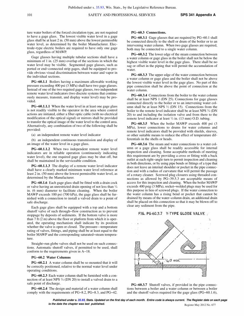
PG−60.3.6 The steam and water connections to a water col-umn or a gage glass shall be readily accessible for internalinspection and cleaning. Some acceptable methods of meetingthis requirement are by providing a cross or fitting with a backoutlet at each right−angle turn to permit inspection and cleaningin both directions, or by using pipe bends or fittings of a type thatdoes not leave an internal shoulder or pocket in the pipe connec-tion and with a radius of curvature that will permit the passageof a rotary cleaner. Screwed plug closures using threaded con-nections as allowed by PG−39.5.3 are acceptable means ofaccess for this inspection and cleaning. When the boiler MAWPexceeds 400 psig (3 MPa), socket−welded plugs may be used forthis purpose in lieu of screwed plugs. If the water connection tothe water column has a rising bend or pocket that cannot bedrained by means of the water−column drain, an additional drainshall be placed on this connection so that it may be blown off toclear any sediment from the pipe.
PG−60.3.7 Shutoff valves, if provided in the pipe connec-tions between a boiler and a water column or between a boilerand the shutoff valves required for the gage glass (PG−60.1.6),

102SPS 341 Appendix A WISCONSIN ADMINISTRATIVE CODE
Published under s. 35.93, Wis. Stats., by the Legislative Reference Bureau.
Published under s. 35.93, Stats. Updated on the first day of each month. Entire code is always current. The Register date on each
page is the date the chapter was last published.Register Mary 2012 No. 677
shall be of such through−flow construction as to prevent stop-page by deposits of sediment and shall indicate whether they arein open or closed position of the operating mechanism.
Some examples of acceptable valves are:
(a) outside−screw−and−yoke type gate valve
(b) lever−lifting−type gate valve with permanently fastenedlever
(c) stopcock with the plug held in place by a guard or gland
(d) ball valve
Such valves shall be locked or sealed open except under thefollowing additional conditions:
(1) The boiler MAWP shall not exceed 250 psig (1.7 MPa).
(2) The boiler shall not be hand fired or fired with solid fuelnot in suspension.
(3) Interlocks between the valve and the burner control sys-tem shall stop fuel supply and prevent firing whenever the valvebetween the drum and the water column is not in the fully openposition.
(4) The minimum valve size shall be NPS 1 (DN 25).
PG−60.3.8 Except for control devices such as damper regu-lators and feedwater regulators, drains, steam pressure gages, orapparatus of such form as does not permit the escape of an appre-ciable amount of steam or water therefrom, no outlet connec-tions shall be placed on the piping connecting a water column orgage glass to a boiler. No outlet connections shall be placed onthe piping connecting a remote level indicator to the boiler or toa water column for any function other than water level indica-tion.
PG−60.3.9 An acceptable arrangement is shown in Fig.PG−60.3.9
PG−60.4 Gage Cocks. Not required.
PG−60.5 Water Fronts. Each boiler fitted with a water jack-eted boiler−furnace mouth protector, or similar appliance hav-ing valves on the pipes connecting them to the boiler shall havethese valves locked or sealed open. Such valves, when used,shall be of the straightway type.
PG−60.6 Pressure Gages
PG−60.6.1 Each boiler shall have a pressure gage so locatedthat it is easily readable. The pressure gage shall be installed sothat it shall at all times indicate the pressure in the boiler. Eachsteam boiler shall have the pressure gage connected to the steamspace or to the water column or its steam connection. A valveor cock shall be placed in the gage connection adjacent to thegage. An additional valve or cock may be located near the boilerproviding it is locked or sealed in the open position. No othershutoff valves shall be located between the gage and the boiler.The pipe connection shall be of ample size and arranged so thatit may be cleared by blowing out. For a steam boiler the gageor connection shall contain a syphon or equivalent device thatwill develop and maintain a water seal that will prevent steamfrom entering the gage tube. Pressure gage connections shall besuitable for the maximum allowable working pressure and tem-perature, but if the temperature exceeds 406�F (208�C), brassor copper pipe or tubing shall not be used. The connections tothe boiler, except the syphon, if used, shall not be less than NPS¼ (DN 8) but where steel or wrought iron pipe or tubing is used,they shall not be less than ½ in. (13 mm) inside diameter. Theminimum size of a syphon, if used, shall be ¼ in. (6 mm) insidediameter. The dial of the pressure gage shall be graduated toapproximately double the pressure at which the safety valve isset, but in no case to less than 1 ½ times this pressure.
PG−60.6.2 Each forced−flow steam generator with no fixedsteam and waterline shall be equipped with pressure gages orother pressure measuring devices located as follows:
PG−60.6.2.1 At the boiler or superheater outlet (followingthe last section which involves absorption of heat), and
PG−60.6.2.2 At the boiler or economizer inlet (precedingany section that involves absorption of heat), and
PG−60.6.2.3 Upstream of any shutoff valve that may be usedbetween any two sections of the heat absorbing surface.
PG−60.6.3 Each boiler shall be provided with a valve con-nection at least NPS ¼ (DN 8) for the exclusive purpose ofattaching a test gage when the boiler is in service, so that theaccuracy of the boiler pressure gage can be ascertained.
PG−60.6.4 Each high−temperature water boiler shall have atemperature gage so located and connected that it shall be easilyreadable. The temperature gage shall be installed so that it at alltimes indicates the temperature in degrees Fahrenheit (Celsius)of the water in the boiler, at or near the outlet connection.
PG−61 FEEDWATER SUPPLY
PG−61.1 Except as provided for in PG−61.2 and PG−61.4,boilers having more than 500 ft2 (47 m2) of water−heating sur-face shall have at least two means of feeding water. Except asprovided for in PG−61.3, PG−61.4, and PG−61.5, each source offeeding shall be capable of supplying water to the boiler at apressure of 3% higher than the highest setting of any safety valveon the boiler. For boilers that are fired with solid fuel not in sus-pension, and for boilers whose setting or heat source can con-tinue to supply sufficient heat to cause damage to the boiler if thefeed supply is interrupted, one such means of feeding shall notbe susceptible to the same interruption as the other, and eachshall provide sufficient water to prevent damage to the boiler.
PG−61.2 Except as provided for in PG−61.1, a boiler firedby gaseous, liquid, or solid fuel in suspension, or heated by com-bustion turbine engine exhaust, may be equipped with a singlemeans of feeding water, provided means are furnished for theshutting off of its heat input prior to the water level reaching thelowest permissible level established by PG−60.
PG−61.3 For boilers having a water−heating surface of notmore than 100 ft2 (9.3 m2) the feed connection to the boiler shall

103 SPS 341 Appendix ASAFETY AND PROFESSIONAL SERVICES
Published under s. 35.93, Wis. Stats., by the Legislative Reference Bureau.
Published under s. 35.93, Stats. Updated on the first day of each month. Entire code is always current. The Register date on each page
is the date the chapter was last published. Register May 2012 No. 677
not be smaller than NPS ½ (DN 15). For boilers having a water−heating surface more than 100 ft2 (9.3 m2) the feed connectionto the boiler shall not be less than NPS ¾ (DN 20).
PG−61.4 High−temperature water boilers shall be providedwith means of adding water to the boiler or system while underpressure.
PG−61.5 A forced−flow steam generator with no fixed steamand waterline shall be provided with a source of feeding capableof supplying water to the boiler at a pressure not less than theexpected maximum sustained pressure at the boiler inlet, asdetermined by the boiler Manufacturer, corresponding to opera-tion at maximum designed steaming capacity with maximumallowable working pressure at the superheater outlet.
OVERPRESSURE PROTECTION REQUIREMENTS
PG−67 BOILER
PG−67.1 Each boiler shall have at least one pressure reliefvalve and if it has more than 500 ft2 (47 m2) of bare tube water−heating surface, or if an electric boiler has a power input morethan 1,100 kW, it shall have two or more pressure relief valves.For a boiler with combined bare tube and extended water−heat-ing surface exceeding 500 ft2 (47 m2), two or more pressurerelief valves are required only if the design steam generatingcapacity of the boiler exceeds 4,000 lb/hr (1 800 kg/hr). Organicfluid vaporizer generators require special consideration as givenin Part PVG.
PG−67.2 The pressure relief valve capacity for each boiler(except as noted in PG−67.4) shall be such that the pressurerelief valve, or valves will discharge all the steam that can begenerated by the boiler without allowing the pressure to risemore than 6% above the highest pressure at which any valve isset and in no case to more than 6% above the maximum allow-able working pressure.
PG−67.2.1 The minimum required relieving capacity of thepressure relief valves for all types of boilers shall be not less thanthe maximum designed steaming capacity at the MAWP of theboiler, as determined by the Manufacturer and shall be based onthe capacity of all the fuel burning equipment as limited by otherboiler functions.
PG−67.2.2 The minimum required relieving capacity for awaste heat boiler shall be determined by the Manufacturer.When auxiliary firing is to be used in combination with wasteheat recovery, the maximum output as determined by the boilerManufacturer shall include the effect of such firing in the totalrequired capacity. When auxiliary firing is’ to be used in placeof waste heat recovery, the minimum required relieving capacityshall be based on auxiliary firing or waste heat recovery, which-ever is higher.
PG−67.2.3 The minimum required relieving capacity forelectric boilers shall be in accordance with PEB−15.
PG−67.2.4 The minimum required relieving capacity in lb/hr (kg/hr) for a high−temperature water boiler shall be deter-mined by dividing the maximum output in Btu/hr (W) at theboiler nozzle, produced by the highest heating value fuel forwhich the boiler is designed, by 1,000 (646).
PG−67.2.5 The minimum required relieving capacity fororganic fluid vaporizers shall be in accordance with PVG−12.The minimum required relieving capacity for miniature boilersshall be in accordance with PMB−15.
PG−67.2.6 Any economizer that may be shut off from theboiler, thereby permitting the economizer to become a firedpressure vessel, shall have one or more pressure relief valveswith a total discharge capacity, in lb/hr (kg/hr), calculated fromthe maximum expected heat absorption in Btu/hr (W), as deter-mined by the Manufacturer, divided by 1,000 (646). Thisabsorption s shall be stated in the stamping (PG−106.4). Foroverpressure conditions where the fluid relieved is water, thedischarge capacity of the pressure relief valve, or valves shall besufficient to prevent the pressure from exceeding the limits ofPG−67.2.
PG−67.2.7 The steam generated when all pressure reliefvalves are relieving at full lift on a boiler that has a steam−gener-ating surface located downstream in the gas stream of a super-heater and/or reheater surface may exceed the maximumdesigned steaming capacity at the MA WP of the boiler. TheManufacturer shall address this by one of the following meth-ods:
PG−67.2.7.1 The minimum required relieving capacity ofthe pressure relief valves shall not be less than the steam thatmay be generated with all pressure relief valves relieving at fulllift. For boilers that use auxiliary firing in combination with theprimary heat source, the Manufacturer shall include the effect ofsuch firing in the total required capacity.
PG−67.2.7.2 The minimum required relieving capacity ofthe pressure relief valves shall not be less than the maximumdesigned steaming capacity at the MAWP of the boiler, and theboiler shall be provided with controls responsive to steam pres-sure, which include not less than the following:
(a) a control that reduces that total heat input to the boilersuch that the steam generated does not exceed the maximumdesigned steaming capacity at the MAWP of the boiler
(b) a control that trips the heat input to the boiler if the pres-sure reaches 106% of the MAWP of the boiler.
PG−67.3 One or more pressure relief valves on the boilerproper shall be set at or below the maximum allowable workingpressure (except as noted in PG−67.4). If additional valves areused the highest pressure setting shall not exceed the maximumallowable working pressure by more than 3%. The completerange of pressure settings of all the saturated−steam pressurerelief valves on a boiler shall not exceed 10% of the highestpressure to which any valve is set. Pressure setting of pressurerelief valves on high−temperature water boilers8 may exceedthis 10% range. Economizer pressure relief devices required byPG−67.2.6 shall be set as above using the MAWP of the econo-mizer.
8 Pressure relief valves in hot water service are more susceptible to damage andsubsequent leakage, than pressure relief valves relieving steam. It is recom-mended that the maximum allowable working pressure of the boiler and the pres-sure relief valve setting for high−temperature water boilers be selected substan-tially higher than the desired operating pressure so as to minimize the times thepressure relief valve must lift.
104SPS 341 Appendix A WISCONSIN ADMINISTRATIVE CODE
Published under s. 35.93, Wis. Stats., by the Legislative Reference Bureau.
Published under s. 35.93, Stats. Updated on the first day of each month. Entire code is always current. The Register date on each
page is the date the chapter was last published.Register Mary 2012 No. 677
105 SPS 341 Appendix ASAFETY AND PROFESSIONAL SERVICES
Published under s. 35.93, Wis. Stats., by the Legislative Reference Bureau.
Published under s. 35.93, Stats. Updated on the first day of each month. Entire code is always current. The Register date on each page
is the date the chapter was last published. Register May 2012 No. 677
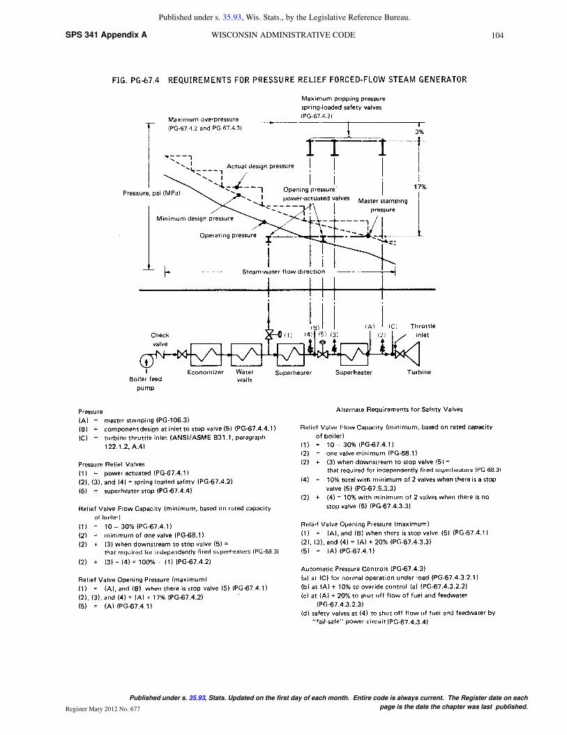
PG−67.4 For a forced−flow steam generator with no fixedsteam and waterline (Fig. PG−6704), equipped with automaticcontrols and protective interlocks responsive to steam pressure,pressure relief valves may be provided in accordance with theabove paragraphs or the following protection against overpres-sure shall be provided:
PG−67.4.1 One or more power−actuated pressure relievingvalves9 shall be provided in direct communication with theboiler when the boiler is under pressure and shall receive a con-trol impulse to open when the maximum allowable workingpressure at the superheater outlet, as shown in the master stamp-ing (PG−106.3), is exceeded. The total combined relievingcapacity of the power−actuated relieving valves shall be not lessthan 10% of the maximum design steaming capacity of theboiler under any operating condition as determined by the Man-ufacturer. The valve or valves shall be located in the pressurepart system where they will relieve the overpressure.
9 The power−actuated pressure relieving valve is one whose movements to openor close are fully controlled by a source of power (electricity, air, steam, orhydraulic). The valve may discharge to atmosphere or to a container at lowerpressure. The discharge capacity may be affected by the downstream conditions,and such effects shall be taken into account. If the power−actuated pressurerelieving valves are also positioned in response to other control signals, the con-trol impulse to prevent overpressure shall be responsive only to pressure andshall override any other control function.
An isolating stop valve of the outside−screw−and−yoke orball type may be installed between the power−actuated pressurerelieving valve and the boiler to permit repairs provided an alter-nate power−actuated pressure relieving valve of the same capac-ity is so installed as to be in direct communication with the boilerin accordance with the requirements of this paragraph.
The isolating stop valve port area shall at least equal the areaof the inlet of the power−actuated pressure relieving valve. If theisolating stop valve is of the ball type, the valve shall include ameans to clearly identify whether the valve is in the open orclosed position. If the isolating stop valve is power actuated (air,motor, hydraulic, etc.), a manual override mechanism shall beprovided.
Power−actuated pressure relieving valves discharging tointermediate pressure and incorporated into bypass and/orstartup circuits by the boiler Manufacturer need not be capacitycertified. Instead, they shall be marked by the valve manufac-turer with a capacity rating at a set of specified inlet pressure andtemperature conditions. Power−actuated pressure relievingvalves discharging directly to atmosphere shall be capacity cer-tified. This capacity certification shall be conducted in accord-ance with the provisions of PG−69.3. The valves shall bemarked in accordance with the provisions of PG−69.4.
PG−67.4.2 Pressure relief valves shall be provided, havinga total combined relieving capacity, including that of the power−actuated pressure relieving capacity installed under PG−67.4.l,of not less than 100% of the maximum designed steaming capac-ity of the boiler, as determined by the Manufacturer, except thealternate provisions of PG−67.4.3 are satisfied. In this total, nocredit in excess of 30% of the total required relieving capacityshall be allowed for the power−actuated pressure relievingvalves actually installed. Any or all of the pressure relief valvesmay be set above the maximum allowable working pressure ofthe parts to which they are connected, but the set pressures shallbe such that when all of these valves (together with the power−actuated pressure relieving valves)are in operation the pressurewill not rise more than 20% above the maximum allowableworking pressure of any part of the boiler, except for the steampiping between the boiler and the prime mover.
PG−67.4.3 The total installed capacity of spring loadedsafety valves may be less than the requirements of PG−67.4.2provided all of the following conditions are met.
PG−67.4.3.1 The boiler shall be of no less steaming capacitythan 1,000,000 lb/hr (450 000 kg/hr) and installed in a unit sys-tem for power generation (i.e., a single boiler supplying a singleturbine−generator unit).
PG−67.4.3.2 The boiler shall be provided with automaticdevices, responsive to variations in steam pressure, whichinclude not less than all the following:
PG−67.4.3.2.1 A control capable of maintaining steam pres-sure at the desired operating level and of modulating firing ratesand feedwater flow in proportion to a variable steam output.
PG−67.4.3.2.2 A control that overrides PG−67.4.3.2.1 byreducing the fuel rate and feedwater flow when the steam pres-sure exceeds the maximum allowable working pressure asshown in the master stamping (PG−106.3) by 10%; and
PG−67.4.3.2.3 A direct−acting overpressure−trip−actuatingmechanism, using an independent pressure sensing device, thatwill stop the flow of fuel and feedwater to the boiler, at a pressurehigher than the set pressure of PG−67.4.3.2.2, but less than 20%above the maximum allowable working pressure as shown in themaster stamping (PG−106.3).
PG−67.4.3.3 There shall be not less than two pressure reliefvalves and the total rated relieving capacity of the pressure reliefvalves shall be not less than 10% of the maximum designedsteaming capacity of the boiler as determined by the Manufac-turer. These pressure relief valves may be set above the maxi-mum allowable working pressure of the parts to which they areconnected but shall be set such that the valves will lift at a pres-sure no higher than 20% above the maximum allowable workingpressure as shown in the master stamping (PG−106.3).
PG−67.4.3.4 At least two of these pressure relief valves shallbe equipped with a device that directly transmits the valve stemlift action to controls that will stop the flow of fuel and feedwaterto the boiler. The control circuitry to accomplish this shall bearranged in a ”fail−safe” manner (see Note).
NOTES: “Fail−safe” shall mean a circuitry arranged as either of the fol-lowing:
(a) Energize to trip: There shall be at least two separate and independent
trip circuits served by two power sources, to initiate and perform the trip
action. One power source shall be a continuously charged DC battery. The
second source shall be an AC−to−DC converter connected to the DC system
to charge the battery and capable of performing the trip action. The trip cir-
cuits shall be continuously monitored for availability.
It is not mandatory to duplicate the mechanism that actually stops the flow
of fuel and feedwater.
(b) De−energize to trip: If the circuits are arranged in such a way that a
continuous supply of power is required to keep the circuits closed and operat-
ing and such that any interruption of power supply will actuate the trip mecha-
nism, then a single trip circuit and single power supply will be enough to meet
the requirements of this subparagraph.
PG−67.4.3.5 The power supply for all controls and devicesrequired by PG−67.4.3 shall include at least one source con-tained within the same plant as the boiler and which is arrangedto actuate the controls and devices continuously in the event offailure or interruption of any other power sources.
PG−67.4.4 When stop valves are installed in the water−steam flow path between any two sections of a forced−flowsteam generator with no fixed steam and waterline:
PG−67.4.4.1 The power−actuated pressure relievingvalve(s) required by PG−67.4.1 shall also receive a controlimpulse to open when the maximum allowable working pres-sure of the component, having the lowest pressure upstream tothe stop valve, is exceeded; and
106SPS 341 Appendix A WISCONSIN ADMINISTRATIVE CODE
Published under s. 35.93, Wis. Stats., by the Legislative Reference Bureau.
Published under s. 35.93, Stats. Updated on the first day of each month. Entire code is always current. The Register date on each
page is the date the chapter was last published.Register Mary 2012 No. 677
PG−67.4.4.2 The pressure relief valves shall be located toprovide the pressure protection requirements in PG−67.4.2 orPG−67.4.3.
PG−67.4.5 A reliable pressure−recording device shallalways be in service and records kept to provide evidence of con-formity to the above requirements.
PG−67.5 The coefficient of discharge of pressure reliefvalves shall be determined by actual steam flow measurementsat a pressure not more than 3% above the pressure at which thevalve is set to relieve and when adjusted for blowdown in accor-dance with PG−69.1.4. The valves shall be credited with capaci-ties as determined by the provisions of PG−69.2.
Pressure relief valves may be used that give any opening upto the full discharge capacity of the area of the opening of theinlet of the valve, provided the movement of a steam pressurerelief valve is such as not to induce lifting of water in the boiler.
For high−temperature water boilers pressure relief valvesshall be used. Such valves shall have a closed bonnet. In addi-tion the pressure relief valves shall be capable of satisfactoryoperation when relieving water at the saturation temperaturecorresponding to the pressure at which the valve is set to blow.
PG−68 SUPERHEATER AND REHEATER
PG−68.1 Except as permitted in PG−58.3.1, every attachedsuperheater shall have one or more pressure relief valves in thesteam flow path between the superheater outlet and the first stopvalve. The location shall be suitable for the service intended andshall provide the overpressure protection required. The pressuredrop upstream of each pressure relief valve shall be consideredin the determination of set pressure and relieving capacity of thatvalve. If the superheater outlet header has a full, free steam pas-sage from end to end and is so constructed that steam is suppliedto it at practically equal intervals throughout its length so thatthere is a uniform flow of steam through the superheater tubesand the header, the pressure relief valve, or valves, may belocated anywhere in the length of the header.
PG−68.2 The discharge capacity of the pressure relief valve,or valves, on an attached superheater may be included in deter-mining the number and size of the pressure relief valves for theboiler, provided there are no intervening valves between thesuperheater pressure relief valve and the boiler, and provided thedischarge capacity of the pressure relief valve, or valves, on theboiler, as distinct from the superheater is at least 75% of theaggregate valve capacity required.
PG−68.3 Every isolable superheater that may be shut offfrom the boiler and permit the superheater to become a fired
pressure vessel and all nonintegral separately fired superheatersshall have one or more pressure relief valves having a dischargecapacity equal to 6 lb/ft2 (29 kg/m2) of steam per hour, using thesuperheater surface measured on the side exposed to the hotgases. As an alternative the Manufacturer may also calculate theminimum pressure relief valve discharge capacity in lb (kg) ofsteam per hour from the maximum expected heat absorption (asdetermined by the Manufacturer) in Btu/hr (W), divided by1,000 (646). In the case of electrically heated superheaters, thepressure relief valve capacity shall be based upon 3 ½ lb (1.6kg)/hr/kW input. The number of pressure relief valves installedshall be such that the total capacity is at least equal to thatrequired. Pressure relief valves for separately fired superheatersshall be located in accordance with the rules of PG−68.1 and themounting rules of PG−71.
PG−68.4 Every reheater shall have one or more pressurerelief valves, such that the total relieving capacity is at leastequal to the maximum steam flow for which the heater isdesigned. The capacity of the reheater pressure relief valvesshall not be included in the required relieving capacity for theboiler and superheater.
One or more pressure relief valves with a combined relievingcapacity not less than 15% of the required total shall be locatedalong the steam flow path between the reheater outlet and thefirst stop valve. The pressure drop upstream of the pressurerelief valves on the outlet side of the reheater shall be consideredin determining their set pressure.
PG−68.5 A soot blower connection may be attached to thesame outlet from the superheater or reheater that is used for thepressure relief valve connection.
PG−68.6 Every pressure relief valve used on a superheateror reheater discharging superheated steam at a temperature over450�F (230°C) shall have a casing, including the base, body,and, if applicable, bonnet and spindle, of steel, steel alloy, orequivalent heat−resisting material.
The pressure relief valve shall have a flanged inlet connec-tion, or a weld−end inlet connection. It shall have the seat anddisk of suitable heat erosive and corrosive resisting material, andthe spring of direct spring−loaded safety valves shall be fullyexposed outside of the valve casing so that it shall be protectedfrom contact with the escaping steam.
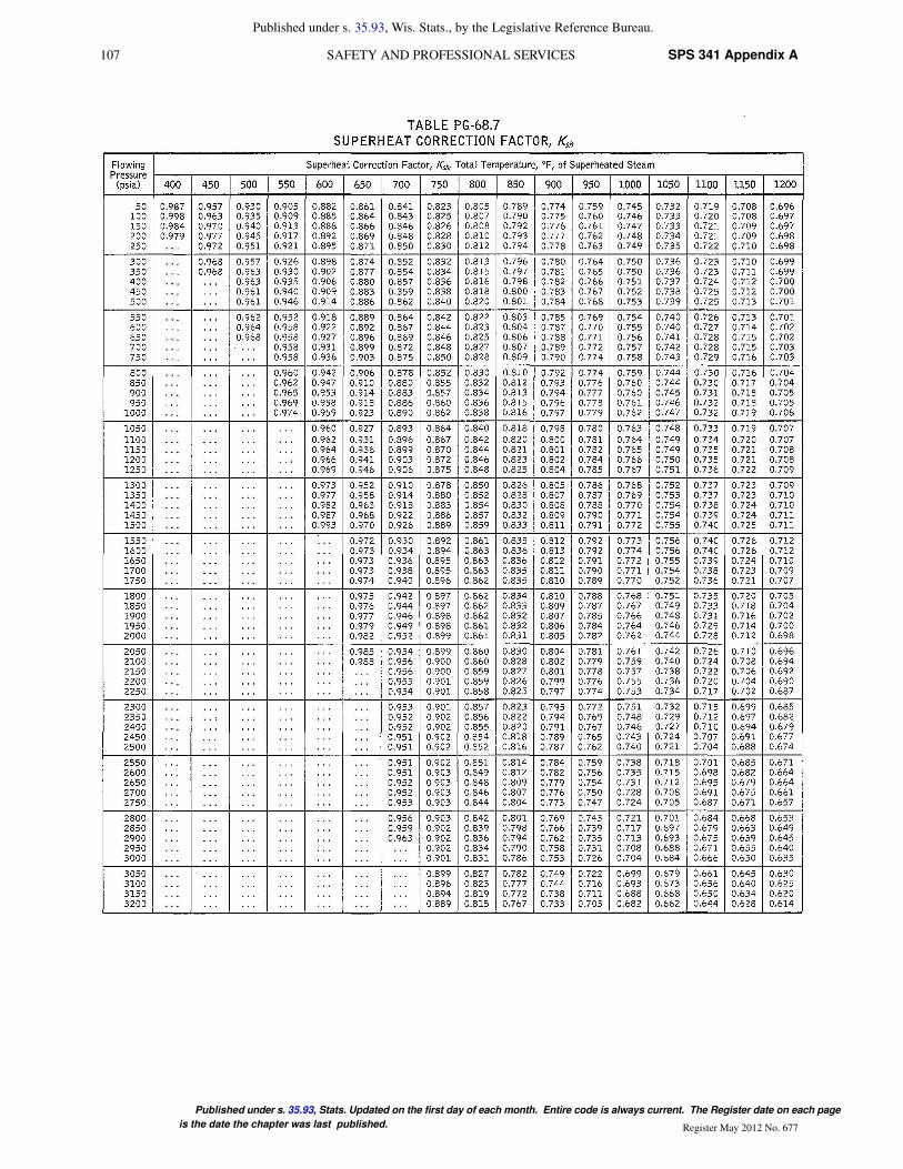
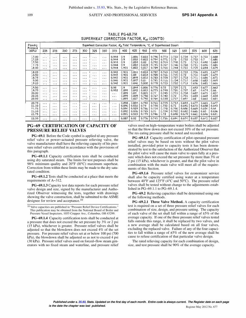
PG−68.7 The capacity of a pressure relief valve on super-heated steam shall be calculated by multiplying the capacitydetermined in accordance with PG−69.2 by the appropriatesuperheat correction factor Ksh , from Table PG−68.7.
107 SPS 341 Appendix ASAFETY AND PROFESSIONAL SERVICES
Published under s. 35.93, Wis. Stats., by the Legislative Reference Bureau.
Published under s. 35.93, Stats. Updated on the first day of each month. Entire code is always current. The Register date on each page
is the date the chapter was last published. Register May 2012 No. 677

108SPS 341 Appendix A WISCONSIN ADMINISTRATIVE CODE
Published under s. 35.93, Wis. Stats., by the Legislative Reference Bureau.
Published under s. 35.93, Stats. Updated on the first day of each month. Entire code is always current. The Register date on each
page is the date the chapter was last published.Register Mary 2012 No. 677
109 SPS 341 Appendix ASAFETY AND PROFESSIONAL SERVICES
Published under s. 35.93, Wis. Stats., by the Legislative Reference Bureau.
Published under s. 35.93, Stats. Updated on the first day of each month. Entire code is always current. The Register date on each page
is the date the chapter was last published. Register May 2012 No. 677
PG−69 CERTIFICATION OF CAPACITY OFPRESSURE RELIEF VALVES
PG−69.1 Before the Code symbol is applied td any pressurerelief valve or power−actuated pressure relieving valve, thevalve manufacturer shall have the relieving capacity of his pres-sure relief valves certified in accordance with the provisions ofthis paragraph.
PG−69.1.1 Capacity certification tests shall be conductedusing dry saturated steam. The limits for test purposes shall be98% minimum quality and 20°F (l0°C) maximum superheat.Correction from within these limits may be made to the dry satu-rated condition.
PG−69.1.2 Tests shall be conducted at a place that meets therequirements of A−312.
PG−69.1.3 Capacity test data reports for each pressure reliefvalve design and size, signed by the manufacturer and Autho-rized Observer witnessing the tests, together with drawingsshowing the valve construction, shall be submitted to the ASMEdesignee for review and acceptance.10
10 Valve capacities are published in “Pressure Relief Device Certifications.”This publication may be obtained from the National Board of Boiler andPressure Vessel Inspectors, 1055 Crupper Ave., Columbus, OH 43299.
PG−69.1.4 Capacity certification tests shall be conducted ata pressure that does not exceed the set pressure by 3% or 2 psi(15 kPa), whichever is greater. Pressure relief valves shall beadjusted so that the blowdown does not exceed 4% of the setpressure. For pressure relief valves set at or below 100 psi (700kPa), the blowdown shall be adjusted so as not to exceed 4 psi(30 kPa). Pressure relief valves used on forced−flow steam gen-erators with no fixed steam and waterline, and pressure relief
valves used on high−temperature water boilers shall be adjustedso that the blow down does not exceed 10% of the set pressure.The res eating pressure shall be noted and recorded.
PG−69.1.5 Capacity certification of pilot operated pressurerelief valves may be based on tests without the pilot valvesinstalled, provided prior to capacity tests it has been demon-strated by test to the satisfaction of the Authorized Observer thatthe pilot valve will cause the main valve to open fully at a pres-sure which does not exceed the set pressure by more than 3% or2 psi (15 kPa), whichever is greater, and that the pilot valve incombination with the main valve will meet all of the require-ments of this Section.
PG−69.1.6 Pressure relief valves for economizer serviceshall also be capacity certified using water at a temperaturebetween 40°F and 125°F (4°C and 50°C). The pressure reliefvalves shall be tested without change to the adjustments estab-lished in PG−69.1.1 to PG−69.1.4.
PG−69.2 Relieving capacities shall be determined using oneof the following methods.
PG−69.2.1 Three Valve Method. A capacity certificationtest is required on a set of three pressure relief valves for eachcombination of size, design, and pressure setting. The capacityof each valve of the set shall fall within a range of ±5% of theaverage capacity. If one of the three pressure relief valves testedfalls outside this range, it shall be replaced by two valves, anda new average shall be calculated based on all four valves,excluding the replaced valve. Failure of any of the four capaci-ties to fall within a range of ±5% of the new average shall because to refuse certification of that particular valve design.
The rated relieving capacity for each combination of design,size, and test pressure shall be 90% of the average capacity.

110SPS 341 Appendix A WISCONSIN ADMINISTRATIVE CODE
Published under s. 35.93, Wis. Stats., by the Legislative Reference Bureau.
Published under s. 35.93, Stats. Updated on the first day of each month. Entire code is always current. The Register date on each
page is the date the chapter was last published.Register Mary 2012 No. 677

111 SPS 341 Appendix ASAFETY AND PROFESSIONAL SERVICES
Published under s. 35.93, Wis. Stats., by the Legislative Reference Bureau.
Published under s. 35.93, Stats. Updated on the first day of each month. Entire code is always current. The Register date on each page
is the date the chapter was last published. Register May 2012 No. 677
PG−69.2.2 Slope Method. If a Manufacturer wishes toapply the Code Symbol to a design of pressure relief valves, fourvalves of each combination of pipe size and orifice size shall betested. These four valves shall be set at pressures that cover theapproximate range of pressures for which the valve will be usedor covering the range available at the certified test facility thatshall conduct the tests. The capacities based on these four testsshall be as follows:
(a) The slope WIP of the actual measured capacity versus theflow pressure for each test point shall be calculated and averaged
For steam
For water
All values derived from the testing must fall within ±5% ofthe average value:
minimum slope = 0.95 x average slope
maximum slope = 1.05 x average slope
If the values derived from the testing do not fall between theminimum and maximum slope values, the Authorized Observershall require that additional valves be tested at the rate of two foreach valve beyond the maximum and minimum values with alimit of four additional valves.
For steam applications the relieving capacity to be stampedon the valve shall not exceed 90% of the average slope times theabsolute accumulation pressure
rated slope = 0.90 x average slope
For water applications the relieving capacity shall not exceed90% of the average slope multiplied by the square root of the dif-ference between the flow rating pressure and the valve dischargepressure.
(U.S. Customary Units)
stamped capacity ≤ rated slope (1.03 x set pressure + 14.7) or(set pressure + 2 psi + 14.7), whichever is greater
(SI Units)
stamped capacity ≤ rated slope (1.03 x set pressure + 0.101)or (set pressure + 0.015 MPa + 0.101), whichever is greater
112SPS 341 Appendix A WISCONSIN ADMINISTRATIVE CODE
Published under s. 35.93, Wis. Stats., by the Legislative Reference Bureau.
Published under s. 35.93, Stats. Updated on the first day of each month. Entire code is always current. The Register date on each
page is the date the chapter was last published.Register Mary 2012 No. 677

113 SPS 341 Appendix ASAFETY AND PROFESSIONAL SERVICES
Published under s. 35.93, Wis. Stats., by the Legislative Reference Bureau.
Published under s. 35.93, Stats. Updated on the first day of each month. Entire code is always current. The Register date on each page
is the date the chapter was last published. Register May 2012 No. 677
PG−69.2.3 Coefficient of Discharge Method. A coefficientof discharge for the design, K, may be established for a specificvalve design according to the following procedure:
(a) For each design, the pressure relief valve manufacturershall submit for test at least three valves for each of three differ-ent sizes (a total of nine valves). Each valve of a given size shallbe set at a different pressure, covering the range of pressures forwhich the valve will be used or the range available at the facilitywhere the tests are conducted.
For each valve design where the coefficient of discharge hasbeen determined that is intended to be restricted in lift, the Man-ufacturer shall have capacity tests conducted on three valves ofdifferent sizes. Each size valve shall be tested for capacity at theminimum lift for which certification is required, and at two inter-mediate lift points between the full rated lift and minimum liftcertification points. Each of the three test valves shall be set ata different pressure.
For each valve tested, it shall be verified that actual measuredcapacity at restricted lift will equal or exceed the rated capacityat full rated lift multiplied by the ratio of measured restricted liftto full rated lift.
(b) Tests shall be made on each pressure relief valve to deter-mine its lift at capacity, popping, and blowdown pressures, andactual relieving capacity. An individual coefficient, KD , shall beestablished for each valve as follows:
Where actual flow is determined by test and theoretical flow,WT is calculated by one of the following equations:
For tests with dry saturated steam
For 45 deg seat
(U.S. Customary Units)
WT = 51.5 x πDLP x 0.707
(SI Units)
WT = 5.25 x πDLP x 0.707
For flat seat
(U.S. Customary Units)
WT = 51.5 x πDLP
(SI Units)
WT = 5.25 x πDLP
For nozzle
(U.S. Customary Units)
WT = 51.5 AP
(SI Units)
WT = 5.25 AP
For tests with water
114SPS 341 Appendix A WISCONSIN ADMINISTRATIVE CODE
Published under s. 35.93, Wis. Stats., by the Legislative Reference Bureau.
Published under s. 35.93, Stats. Updated on the first day of each month. Entire code is always current. The Register date on each
page is the date the chapter was last published.Register Mary 2012 No. 677
For 45 deg seat
(U.S. Customary Units)
(SI Units)
For flat seat
(U.S. Customary Units)
(SI Units)
For nozzle
(U.S. Customary Units)
(SI Units)
where
A = nozzle throat area, in.2 (mm2)
D = seat diameter, in. (mm)
L = lift at pressure P, in. (mm)
P = (1.03 X set pressure + 14.7), psia, or
= (set pressure + 2 + 14.7), psia, whichever is greater
= (1.03 X set pressure + 0.101), MPa, or
= (set pressure + 0.014 + 0.101), MPa, whichever is greater
P d = pressure at discharge of the valve, psia (MPa)
WT = theoretical flow, lb/hr (kg/hr)
w = specific weight of water at inlet conditions, lb/ft3 (kg/m3)
To convert lb/hr of water to gal/min of water, multiply thecapacity in lb/hr by 1/500, To convert kg/hr of water to liter/minof water, multiply the capacity in liter/min by 1/60.
The average of the coefficients KD of the nine tests requiredshall be multiplied by 0.90, and this product shall be taken as thecoefficient K of that design. All individual coefficients of dis-charge, KD, shall fall within a range of ±5% of the average coeffi-cient found. If a valve fails to meet this requirement, the Autho-rized Observer shall require two additional valves to be tested asreplacements for each valve having an individual coefficient,KD, outside the ±5% range, with a limit of four additional valves.Failure of a coefficient, KD, to fall within ±5% of the new aver-age value, excluding the replaced valve(s), shall be cause torefuse certification of that particular valve design.
The rated relieving capacity of all sizes and set pressures ofa given design, for which K has been established under the provi-sion of this paragraph, shall be determined by the equation:
W ≤ WT x K
where
K = coefficient of discharge for the design
W = rated relieving capacity, lb/hr (kg/hr)
WT = theoretical flow, defined by the same equation used todetermine KD, lb/hr (kg/hr)
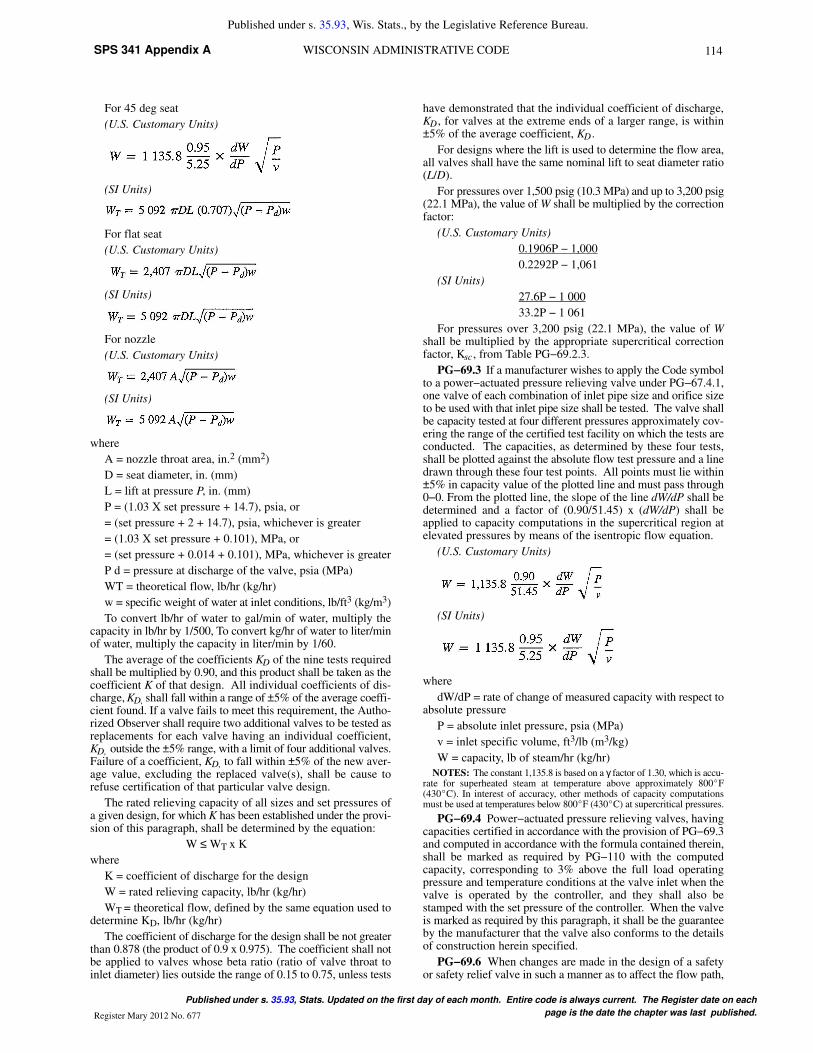
The coefficient of discharge for the design shall be not greaterthan 0.878 (the product of 0.9 x 0.975). The coefficient shall notbe applied to valves whose beta ratio (ratio of valve throat toinlet diameter) lies outside the range of 0.15 to 0.75, unless tests
have demonstrated that the individual coefficient of discharge,KD , for valves at the extreme ends of a larger range, is within±5% of the average coefficient, KD .
For designs where the lift is used to determine the flow area,all valves shall have the same nominal lift to seat diameter ratio(L/D).
For pressures over 1,500 psig (10.3 MPa) and up to 3,200 psig(22.1 MPa), the value of W shall be multiplied by the correctionfactor:
(U.S. Customary Units)
0.1906P − 1,000
0.2292P − 1,061
(SI Units)
27.6P − 1 000
33.2P − 1 061
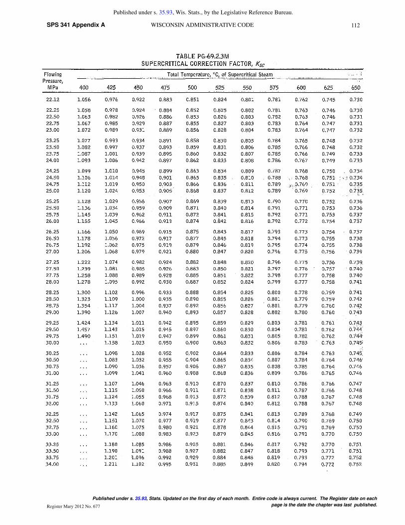
For pressures over 3,200 psig (22.1 MPa), the value of Wshall be multiplied by the appropriate supercritical correctionfactor, Ksc, from Table PG−69.2.3.
PG−69.3 If a manufacturer wishes to apply the Code symbolto a power−actuated pressure relieving valve under PG−67.4.1,one valve of each combination of inlet pipe size and orifice sizeto be used with that inlet pipe size shall be tested. The valve shallbe capacity tested at four different pressures approximately cov-ering the range of the certified test facility on which the tests areconducted. The capacities, as determined by these four tests,shall be plotted against the absolute flow test pressure and a linedrawn through these four test points. All points must lie within±5% in capacity value of the plotted line and must pass through0−0. From the plotted line, the slope of the line dW/dP shall bedetermined and a factor of (0.90/51.45) x (dW/dP) shall beapplied to capacity computations in the supercritical region atelevated pressures by means of the isentropic flow equation.
(U.S. Customary Units)
(SI Units)
where
dW/dP = rate of change of measured capacity with respect toabsolute pressure
P = absolute inlet pressure, psia (MPa)
v = inlet specific volume, ft3/lb (m3/kg)
W = capacity, lb of steam/hr (kg/hr)
NOTES: The constant 1,135.8 is based on a γ factor of 1.30, which is accu-rate for superheated steam at temperature above approximately 800�F(430�C). In interest of accuracy, other methods of capacity computationsmust be used at temperatures below 800�F (430�C) at supercritical pressures.
PG−69.4 Power−actuated pressure relieving valves, havingcapacities certified in accordance with the provision of PG−69.3and computed in accordance with the formula contained therein,shall be marked as required by PG−110 with the computedcapacity, corresponding to 3% above the full load operatingpressure and temperature conditions at the valve inlet when thevalve is operated by the controller, and they shall also bestamped with the set pressure of the controller. When the valveis marked as required by this paragraph, it shall be the guaranteeby the manufacturer that the valve also conforms to the detailsof construction herein specified.
PG−69.6 When changes are made in the design of a safetyor safety relief valve in such a manner as to affect the flow path,

115 SPS 341 Appendix ASAFETY AND PROFESSIONAL SERVICES
Published under s. 35.93, Wis. Stats., by the Legislative Reference Bureau.
Published under s. 35.93, Stats. Updated on the first day of each month. Entire code is always current. The Register date on each page
is the date the chapter was last published. Register May 2012 No. 677
lift, or performance characteristics of the valve, new tests inaccordance with this Section shall be performed.
PG−70 CAPACITY OF PRESSURE RELIEF VALVES
PG−70.1 Subject to the minimum number required byPG−67.1, the number of pressure relief valves required shall bedetermined on the basis of the maximum designed steamingcapacity, as determined by the boiler Manufacturer, and therelieving capacity marked on the valves by the manufacturer.
PG−71 MOUNTING OF PRESSURE RELIEFVALVES
PG−71.1 When two or more pressure relief valves are usedon a boiler, they may be mounted either separately or as twinvalves made by placing individual valves on Y−bases, or duplexvalves having two valves in the same body casing. Twin valvesmade by placing individual valves on Y−bases, or duplex valveshaving two valves in the same body, shall be of approximatelyequal capacity.
When not more than two valves of different sizes aremounted singly the relieving capacity of the smaller valve shallbe not less than 50% of that of the larger valve.
PG−71.2 The pressure relief valve or valves shall be con-nected to the boiler independent of any other connection, andattached as close as possible to the boiler or the normal steamflow path, without any unnecessary intervening pipe or fitting.Such intervening pipe or fitting shall be not longer than the face−to−face dimension of the corresponding tee fitting of the samediameter and pressure under the applicable ASME Standardlisted in PG−42 and shall also comply with PG−8 and PG−39.Every pressure relief valve shall be connected so as to stand inan upright position, with spindle vertical. On high−temperaturewater boilers of the watertube forced−circulation type, the valveshall be located at the boiler outlet.
PG−71.3 The opening or connection between the boiler andthe pressure relief valve shall have at least the area of the valveinlet. No valve of any description shall be placed between therequired pressure relief valve or valves and the boiler, nor on thedischarge pipe between the pressure relief valve and the atmo-sphere. When a discharge pipe is used, the cross−sectional areashall be not less than the full area of the valve outlet or of the total
of the areas of the valve outlets, discharging thereinto. It shall
be as short and straight as possible and so arranged as to avoidundue stresses on the valve or valves.
All pressure relief valve discharges shall be so located orpiped as to be carried clear from running boards or platforms.Ample provision for gravity drain shall be made in the dischargepipe at or near each pressure relief valve, and where water ofcondensation may collect. Each valve shall have an open gravitydrain through the casing below the level of the valve seat. Foriron− and steel−bodied valves exceeding NPS 2 ½ (DN 65), thedrain hole shall be tapped not less than NPS 3/8 (DN 10).
Discharge piping from pressure relief valves on high temper-ature water boilers shall be provided with adequate provisionsfor water drainage as well as the steam venting.
The installation of cast iron bodied pressure relief valves forhigh−temperature water boilers is prohibited.
PG−71.4 If a muffler is used on a pressure relief valve, it shallhave sufficient outlet area to prevent back pressure from inter-fering with the proper operation and discharge capacity of thevalve. The muffler plates or other devices shall be so con-structed as to avoid a possibility of restriction of the steam pas-sages due to deposit. Mufflers shall not be used on high−temper-ature water boiler pressure relief valves.
When a pressure relief valve is exposed to outdoor elementsthat may affect operation of the valve, it is permissible to shieldthe valve with a satisfactory cover. The shield or cover shall be
properly vented and arranged to permit servicing and normaloperation of the valve.
PG−71.5 When a boiler is fitted with two or more pressurerelief valves on one connection, this connection to the boilershall have a cross−sectional area not less than the combinedareas of inlet connections of all the pressure relief valves withwhich it connects and shall also meet the requirements ofPG−71.3.
PG−71.6 Pressure relief valves may be attached to drums orheaders by welding provided the welding is done in accordancewith Code requirements.
PG−71.7 Every boiler shall have proper outlet connectionsfor the required pressure relief valve, or valves, independent ofany other outside steam connection,. the area of opening to beat least equal to the aggregate areas of inlet connections of all ofthe pressure relief valves to be attached thereto. An internal col-lecting pipe, splash plate, or pan may be used, provided the totalarea for inlet of steam thereto is not less than twice the aggregateareas of the inlet connections of the attached pressure reliefvalves. The holes in such collecting pipes shall be at least ¼ in.(6 mm) in diameter and the least dimension in any other form ofopening for inlet of steam shall be ¼ in. (6 mm).
Such dimensional limitations to operation for steam need notapply to steam scrubbers or driers provided the net free steaminlet area of the scrubber or drier is at least 10 times the total areaof the boiler outlets for the pressure relief valves.
PG−71.8 If pressure relief valves are attached to a separatesteam drum or dome, the opening between the boiler proper andthe steam drum or dome shall be not less than required byPG−71.7.
PG−72 OPERATION OF PRESSURE RELIEFVALVES
PG−72.1 Pressure relief valves shall be designed and con-structed to operate without chattering, with a minimum blow-down of 2 psi (15 kPa) or 2% of the set pressure, whichever isgreater, and to attain full lift at a pressure not greater than 3%above their set pressure.
Pressure relief valves used on forced−flow steam generatorswith no fixed steam and waterline, and pressure relief valvesused on high−temperature water boilers must be marked forthese special services by the valve Manufacturer or Assembler.
PG−72.2 The set pressure tolerance plus or minus shall notexceed that specified in the following table:
Set Pressure, psi (MPa)
Tolerance, Plus orMinus From Set
Pressure
≤ 70 (0.5) 2 psi (15 kPa)
> 70 (0.5) and ≤ 300 (2.1) 3% of set pressure
> 300 (2.1) and ≤ 1,000 (7.0) 10 psi (70 kPa)
> 1,000 (7.0) 1% of set pressure
PG−72.3 The spring in a pressure relief valve shall not bereset for any pressure more than 5% above or below that forwhich the valve is marked unless the new setting is within thespring design range established by the manufacturer or is deter-mined to be acceptable to the manufacturer.
If the set pressure is to be adjusted within the limits specifiedabove, the adjustment shall be performed by the manufacturer,his authorized representative, or an assembler. An additionalvalve data tag identifying the new set pressure, capacity, anddate shall be furnished and installed, and the valve shall beresealed.
PG−72.4 If the set pressure of a valve is changed so as torequire a new spring, the spring shall be acceptable to the manu-facturer. The spring installation and valve adjustment shall be

116SPS 341 Appendix A WISCONSIN ADMINISTRATIVE CODE
Published under s. 35.93, Wis. Stats., by the Legislative Reference Bureau.
Published under s. 35.93, Stats. Updated on the first day of each month. Entire code is always current. The Register date on each
page is the date the chapter was last published.Register Mary 2012 No. 677
performed by the manufacturer, his authorized representative, oran assembler. A new nameplate as described in PG−110 shall befurnished and installed, and the valve shall be resealed.
PG−73 MINIMUM REQUIREMENTS FORPRESSURE RELIEF VALVES
PG−73.1 Permissible Pressure Relief Valves
PG−73.1.1 Pressure relief valves shall be either directspring−loaded safety valves, direct spring−loaded safety reliefvalves, or pilot−operated pressure relief valves.
PG−73.1.2 Power−actuated pressure relieving valves shallonly be used for applications specified in PG−67.4.1.
PG−73.1.3 Deadweight or weighted lever safety valves orsafety relief valves shall not be used.
PG−73.1.4 Unless otherwise defined, the definitions relatingto pressure relief devices in ASME PTC 25 shall apply.
PG−73.2 Minimum Requirements
PG−73.2.1 All pressure relief valves shall be so constructedthat the failure of any part cannot obstruct the free and full dis-charge of steam and water from the valve. Pressure relief valvesshall have the seat inclined at any angle between 45 deg and 90deg, inclusive, to the centerline of the disk.
PG−73.2.2 The design shall incorporate guiding arrange-ments necessary to insure consistent operation and tightness.
PG−73.2.3 The spring shall be designed so that the full liftspring compression shall be no greater than 80% of the nominalsolid deflection. The permanent set of the spring (defined as thedifference between the free height and height measured 10 minafter the spring has been compressed solid three additional timesafter presetting at room temperature) shall not exceed 0.5% ofthe free height.
PG−73.2.4 To provide a means for verifying whether it isfree, each safety valve or safety relief valve shall have a substan-tial lifting device, which when activated will release the seatingforce on the disk when the valve is subjected to pressure of atleast 75% of the set pressure. The lifting device shall be such thatit cannot lock or hold the valve disk in lifted position when theexterior lifting force is released. Disks of pressure relief valvesused on high−temperature water boilers shall not be lifted whilethe temperature of the water exceeds 200°F (93°C). If it isdesired to lift the valve disk to assure that it is free, this shall bedone when the valve is subjected to a pressure of at least 75% ofthe set pressure. Pilot−operated pressure relief valves shall beprovided with either a lifting device as described above or meansfor connecting and applying pressure to the pilot adequate toverify that the moving parts critical to proper operations are freeto move. For high−temperature water boilers, the lifting mecha-nism shall be sealed against leakage.
PG−73.2.5 The seat of a pressure relief valve shall be fas-tened to the body of the valve in such a way that there is no possi-bility of the seat lifting.
PG−73.2.6 A body drain below seat level shall be providedin the valve and this drain shall not be plugged during or afterfield installation. For valves exceeding NPS 2 ½ (DN 65), thedrain hole or holes shall be tapped not less than NPS 3/8 (DN10). For valves of NPS 2 ½ (DN 65) or smaller, the drain holeshall not be less than ¼ in. (6 mm) in diameter.
PG−73.2.7 In the design of the body of the valve, consider-ation shall be given to minimizing the effects of water deposits.
PG−73.2.8 Valves having screwed inlet or outlet connec-tions shall be provided with wrenching surfaces to allow for nor-mal installation without damaging operating parts.
PG−73.2.9 Means shall be provided in the design of allvalves for use under this Section, for sealing all external adjust-ments. Seals shall be installed by the manufacturer, his autho-
rized representative, or an assembler at the time of the initialadjustment. After spring replacement and/or subsequent adjust-ment, the valve shall be resealed. Seals shall be installed in sucha manner as to prevent changing the adjustment without break-ing the seal and, in addition, shall serve as a means of identifyingthe manufacturer, his authorized representative, or the assem-bler making the adjustment.
PG−73.2.10 Valve capacity may be restricted by restrictingthe lift of a valve provided the following requirements are met:
(a) The valve size shall be NPS ¾ (DN 20) or larger.
(b) No changes shall be made in the design of the valveexcept to change the valve lift by use of a lift restraining devicedescribed in (c) below.
(c) The restriction of valve capacity shall be permitted onlyby the use of a lift restraining device which shall limit valve liftand shall not otherwise interfere with flow through the valve.The design of the lift restraining device shall be subject to reviewby an ASME designee.
(d) The lift restraining device shall be designed so that, ifadjustable, the adjustable feature can be sealed. Seals shall beinstalled by the valve Manufacturer or Assembler at the time ofinitial adjustment.
(e) Valves shall not have their lifts restricted to a value lessthan 30% of full rated lift, or 0.080 in. (2 mm).
(f) When sizing and selecting valves, the restricted lift name-plate capacity shall be determined by multiplying the capacityat full rated lift by the ratio of the restricted lift to the full ratedlift.
PG−73.2.11 A pressure relief valve over NPS 3 (DN 80),used for pressure greater than 15 psig (100 kPa), shall have aflanged inlet connection or a welded inlet connection. Thedimensions of the flanges subjected to boiler pressure shall con-form to the applicable ASME standards as given in PG−42. Thefacing shall be similar to those illustrated in the standard.
PG−73.2.12 The pilot sensing line of pilot−operated pres-sure relief valves shall be adequately protected from freezing.
PG−73.3 Material Selections
PG−73.3.1 Cast iron seats and disks are not permitted.
PG−73.3.2 Adjacent sliding surfaces such as guides anddisks or disk holders shall both be of corrosion−resistant mate-rial. Springs of corrosion−resistant material or having a corro-sion−resistant coating are required. The seats and disks of pres-sure relief valves shall be of suitable material to resist corrosionby the lading fluid.
NOTES: The degree of corrosion resistance, appropriate to the intendedservice, shall be a matter of agreement between the manufacturer and the pur-chaser.
PG−73.3.3 Materials used in bodies and bonnets or yokesshall be listed in Section II, Parts A and B, and identified inTables 1A and 1B of Section II Part D, as permitted for SectionI construction. Materials used in body to bonnet or body to yokebolting shall be listed in ASME B16.34. Materials used in allother parts required for the pressure relieving or retaining func-tion shall be
(a) listed in ASME Section II
(b) listed in ASTM Specifications (see Note below) or
(c) controlled by the manufacturer of the pressure relief valveby a specification ensuring control of chemical and physicalproperties and quality at least equivalent to ASTM Standards(see Note below)
PG−73.3.4 Pressure relief valves may have bronze partscomplying with either SB−61, SB−62 or SB−148, provided themaximum allowable stresses and temperatures do not exceedthe values given in Table 1B of Section II, Part D, and shall bemarked to indicate the class of material used. Such valves shall
117 SPS 341 Appendix ASAFETY AND PROFESSIONAL SERVICES
Published under s. 35.93, Wis. Stats., by the Legislative Reference Bureau.
Published under s. 35.93, Stats. Updated on the first day of each month. Entire code is always current. The Register date on each page
is the date the chapter was last published. Register May 2012 No. 677
not be used on superheaters delivering steam at a temperatureover 450°F (230°C) for SB−61 and SB−148, and 306°F (I50°C)for SB−62, and shall not be used for high−temperature waterboilers.
NOTES: It shall be the manufacturer’s responsibility to ensure that theallowable stresses at temperature meet the requirements of Section II, Part D,Appendix 1, Mandatory Basis for Establishing Stress Values in Tables 1A and1B.
PG−73.4 Inspection of Manufacturing and/or Assembly
PG−73.4.1 A manufacturer shall demonstrate to the satisfac-tion of an ASME designee that his manufacturing, production,and test facilities and quality control procedures will ensureclose agreement between the performance of random produc-tion samples and the performance of those valves submitted forcapacity certification.
PG−73.4.2 Manufacturing, assembly, inspection, and testoperations including capacity, are subject to inspections at anytime by an ASME designee.
PG−73.4.3 A Manufacturer or Assembler may be grantedpermission to apply the V Code Symbol to production pressurerelief valves capacity−certified in accordance with PG−69, pro-vided the following tests are successfully completed. This per-mission shall expire on the sixth anniversary of the date it is ini-tially granted. This permission may be extended for 6−yrperiods if the following tests are successfully repeated within the6−mo period before expiration.
(a) Two sample production pressure relief valves of a sizeand capacity within the capability of an ASME accepted labora-tory shall be selected by an ASME designee. The maximumblowdown for these samples shall not exceed the value specifiedin the following table:
Set Pressure, psi (kPa)MaximumBlowdown
< 67 (500) 4 psi (30 kPa)≥ 67 (500) and ≤ 250 (1 700) 6% of set pressure> 250 (1 700) and < 375 (2 500) 15 psi (100 kPa)≥ 375 (2 500) 4% of set pressure
The blow down for sample valves designed for use on forcedflow steam generators with no fixed steam and waterline orhigh−temperature water boilers shall not exceed 10% of the setpressure.
(b) Operational and capacity tests shall be conducted in thepresence of an ASME designee at an ASME−accepted labora-tory. The valve manufacturer or assembler shall be notified ofthe time of the test and may have representatives present to wit-ness the test.
(c) Should any valve fail to relieve at or above its certifiedcapacity or should it fail to meet performance requirements inPG−72, the test shall be repeated at the rate of two replacementvalves, selected in accordance with PG−73.4.3(a), for eachvalve that failed.
(d) Failure of any of the replacement valves to meet capacityor the performance requirements of this Section shall be causefor revocation within 60 days of the authorization to use theCode symbol on that particular t type of valve. During thisperiod, the Manufacturer or assembler shall demonstrate thecause of such deficiency and the action taken toward againstfuture occurrence.
PG−73.4.4 Use of the Code Symbol Stamp by an assemblerindicates the use of original unmodified parts in strict accord-ance with the instructions of the manufacturer of the valve.
(a) An assembler may transfer original and unmodified pres-sure relief parts produced by the Manufacturer to other Assem-blers, provided the following conditions are met:
(1) both Assemblers have been granted permission to applythe V or UV Code Symbol to the specific valve type in which theparts are to be used
(2) the Quality Control System of the Assembler receivingthe pressure relief valve parts shall define the controls for theprocurement and acceptance of those parts
(3) the pressure relief valve parts are appropriately packaged,marked, or sealed by the Manufacturer to ensure that the partsare
(a) produced, by the Manufacturer
(b) the parts are original and unmodified
(b) However, an assembler may convert original finishedparts by either machining to another finished part or applying acorrosion−resistant coating to valve springs for a specific appli-cation under the following conditions:
(1) Conversions shall be specified by the Manufacturer.Drawings and/or written instructions used for part conversionshall be obtained from the Manufacturer and shall include adrawing or description of the converted part before and after theconversion.
(2) The Assembler’s quality control system, as accepted bya representative from an ASME−designated organization, mustdescribe in detail the conversion of original parts, provisions forinspection and acceptance, personnel training, and control ofcurrent Manufacturer’s drawings and/or written instructions.
(3) The Assembler must document each use of a convertedpart.
(4) The Assembler must demonstrate to the Manufacturer theability to perform each type of conversion. The Manufacturershall document all authorizations granted to perform part con-versions. The Manufacturer and Assembler shall maintain a fileof such authorizations.
(5) For an Assembler to offer restricted lift valves, theAssembler must demonstrate to the satisfaction of the Manufac-turer the ability to perform valve lift restrictions. The Manufac-turer shall document all authorizations granted to restrict the liftof the valves, and shall maintain records of the lift restrictionsmade by the Assembler. The Assembler shall maintain a file ofsuch authorizations.
(6) At least annually a review shall be performed by the Man-ufacturer of an Assembler’s system and conversion capabilities.The Manufacturer shall document the results of these reviews.A copy of this documentation shall be kept on file by the Assem-bler. The review results shall be made available to a representa-tive from an ASME designated organization.
NOTES: Within the requirements of PG−73.4 and PG−73.5, a manufac-turer is defined as a person or organization who is completely responsible fordesign, material selection, capacity certification, manufacture of all compo-nent parts, assembly, testing, sealing, and shipping of pressure relief valvescertified under this Section.
An assembler is defined as a person or organization who purchases or receivesfrom a manufacturer the necessary component parts or valves and assembles,adjusts, tests, seals, and ships pressure relief valves certified under this Sec-tion at a geographical location other than and using facilities other than thoseused by the manufacturer.
PG−73.5 Testing by Manufacturers or Assemblers
PG−73.5.1 Pressure Testing. Each pressure relief valve towhich the Code Symbol Stamp is to be applied shall be subjectedto the following tests by the Manufacturer or Assembler:
(a) The pressure−containing parts of each valve shall behydrostatically tested at a pressure at least 1.5 times the designpressure of the parts. Parts meeting the following criteria shallbe exempt from pressure testing:
(1) the applied stress under hydrostatic test conditions doesnot exceed 50% of the allowable stress; and
118SPS 341 Appendix A WISCONSIN ADMINISTRATIVE CODE
Published under s. 35.93, Wis. Stats., by the Legislative Reference Bureau.
Published under s. 35.93, Stats. Updated on the first day of each month. Entire code is always current. The Register date on each
page is the date the chapter was last published.Register Mary 2012 No. 677
(2) the part is not cast or welded.
(b) Alternatively, testing may be performed pneumatically ata pressure 1.25 times the design pressure of the part. Pneumatictesting can be hazardous; it is therefore recommended that spe-cial precautions be taken when conducting a pneumatic test.
(c) Testing may be done in the component or assembled con-dition.
(d) When the valve is designed for discharging directly toatmosphere, the valve components downstream of the valve diskare exempt from pressure testing.
(e) Valve components downstream of the disk and fully con-tained within the body are exempt from pressure testing.
(f) These tests shall be conducted after all machining andwelding operations on the parts have been completed.
(g) There shall be no sign of leakage.
PG−73.5.2 Every valve shall be tested with steam by themanufacturer or assembler to demonstrate its set point and pres-sure−containing integrity. The blowdown control elements ofthe pressure relief valve shall be set to the Manufacturer’s speci-fications.
PG−73.5.2.1 Tests shall be conducted either on equipmentthat meets the requirements of PG−73.5.6, or on the boiler, byraising the pressure to demonstrate the set pressure.
PG−73.5.2.2 When the valve is beyond the production testequipment capabilities, an alternative test method presented inPG−73.5.2.2.1 or PG−73.5.2.2.2 may be used, provided all ofthe following conditions are met:
(a) testing the valve at full pressure may cause damage to thevalve, or testing of the valve is impractical due to boiler systemoperational safety considerations
(b) the valve lift has been mechanically verified to meet orexceed the required lift
(c) the blow down control elements of the safety valve are setto the valve manufacturer’s specification
(d) the valve design is compatible with the alternative testmethod selected
PG−73.5.2.2.1 The valve, with its lift temporarily restrictedduring the test, if required to prevent valve damage, shall betested on steam to demonstrate set pressure.
PG−73.5.2.2.2 The valve may be fitted with a hydraulic orpneumatic lift assist device and tested on steam at a pressure lessthan the valve set pressure. The lift assist device and test proce-dure shall be calibrated to provide the set pressure setting withinthe tolerance of PG−72.2.
PG−73.5.3 Leak Test
(a) A seat tightness test shall be conducted at maximumexpected operating pressure but at a pressure not exceeding thereseating pressure of the valve. When being tested, a valveexhibiting no sign of leakage shall be considered adequatelytight.
(b) Closed bonnet pressure relief valves designed for dis-charge to a closed system shall be tested with a minimum of 30psig (200 kPa) air or other gas in the secondary pressure zone.There shall be no sign of leakage.11
11 The user may specify a higher test pressure commensurate with the backpressure anticipated in service.
PG−73.5.4 A manufacturer or assembler shall have a docu-mented program for the application, calibration, and mainte-nance of test gages.
PG−73.5. Testing time on steam valves shall be sufficient toassure that test results are repeatable and representative of fieldperformance.
PG−73.5.6 Test fixtures and test drums, where applicable,shall be of adequate size and capacity to assure that the observedset pressure is consistent with the stamped set pressure withinthe tolerance required by PG−72.2.
PG−73.6 Design Requirements. At the time of submissionof valves for capacity certification or testing in accordance withPG−69, the ASME designee has the authority to review designfor conformity with the requirements of this Section and to rejector require modification of designs that do not conform, prior tocapacity testing.
PG−73.7 Code Symbol “V” Stamp. Each pressure reliefvalve to which the Code “V” symbol (see Fig. PG−105.4) willbe applied shall have been fabricated or assembled by a manu-facturer or assembler holding a valid Certificate of Autho-rization (PG−105.2) and c capacity certified in accordance withthe requirements of this Section. A Certified Individual (CI)shall provide oversight to assure that each use of the Code “V”symbol on a pressure relief valve is in accordance with therequirements of this Section, and that each use of the Code “V”symbol is documented on a Certificate of Conformance, FormP−8.
PG−73.7.1 Requirements for the Certified Individual(CI). The CI shall
(a) be an employee of the manufacturer or assembler
(b) be qualified and certified by the manufacturer or assem-bler. Qualifications shall include as a minimum
(1) knowledge of the requirements of this Section for theapplication of the Code “V” symbol
(2) knowledge of the manufacturer’s or assembler’s qualityprogram
(3) training commensurate with the scope, complexity, orspecial nature of the activities to which oversight is to be pro-vided
(c) have a record, maintained and certified by the manufac-turer or assembler, containing objective evidence of the qualifi-cations of the CI and the training program provided
PG−73.7.2 Duties of the Certified Individual (CI). The CIshall
(a) verify that each item to which the Code “V” symbol isapplied has a current capacity certification and meets all applica-ble requirements of this Section
(b) review documentation for each lot of items to be stampedto verify, for the lot, that requirements of this Section have beencompleted
(c) sign the Certificate of Conformance, Form P−8, prior torelease of control of the pressure relief valves
PG−73.7.3 Certificate of Conformance, Form P−8
(a) The Certificate of Conformance, Form P−8, shall be filledout by the manufacturer or assembler and signed by the CertifiedIndividual. Multiple duplicate pressure relief valves may berecorded as a single entry, provided the valves are identical andare produced in the same lot.
(b) The manufacturer’s or assembler’s written quality con-trol program shall include requirements for completion of Cer-tificates of Conformance, Form P−8, and retention, by the manu-facturer or assembler, for a minimum of 5 years.
FABRICATION
PG−75 GENERAL
The fabrication of boilers and parts thereof shall conform tothe general fabrication requirements in the following paragraphsand in addition to the specific requirements for fabrication in the
119 SPS 341 Appendix ASAFETY AND PROFESSIONAL SERVICES
Published under s. 35.93, Wis. Stats., by the Legislative Reference Bureau.
Published under s. 35.93, Stats. Updated on the first day of each month. Entire code is always current. The Register date on each page
is the date the chapter was last published. Register May 2012 No. 677
Parts of this Section that pertain to the methods of constructionused.
PG−76 CUTTING PLATES AND OTHER STOCK
PG−76.1 Plates may be cut by machining, punching, shear-ing, or cutting by the electric arc or gas process, providingenough metal is left at any unfinished edges to meet the require-ments of PG−79.
PG−76.2 When end faces of nozzle or manhole necks are toremain unwelded in the completed vessel, these end faces shallnot be cut by shearing unless at least 1/8 in. (3 mm) of additionalmetal is removed by any method that will produce a smooth fin-ish.
PG−91 QUALIFICATION OF INSPECTORS
The inspection required by this Section shall be by an Inspec-tor employed by an ASME accredited Authorized InspectionAgency,12 that is, the inspection organization of a state ormunicipality of the United States, a Canadian province, or of aninsurance company authorized to write boiler and pressure ves-sel insurance. These Inspectors shall have been qualified bywritten examination under the rules of any state of the UnitedStates or province of Canada which has adopted the Code.
12 Whenever Authorized Inspection Agency or AIA is used in this Code, it shallmean an Authorized Inspection Agency accredited by ASME in accord-ance with the requirements in the latest edition of ASME QAI−1, Qualifica-tion for Authorized Inspection.
PG−93 INSPECTION AND REPAIR OF FLATPLATE IN CORNER JOINTS
PG−93.1 When flat plate greater than ½ in. (13 mm) thick-ness is welded to other pressure parts to form a corner joint, suchas in flat heads [Fig. PG−31, illustrations (g), (i−1), and (i−2)],waterlegs of firebox boilers or combustion chambers of wetbackboilers [Fig. A−8, illustrations (l), (m), (n), and (p)], and theexposed edges of the plate are closer to the edge of the weld thana distance equal to the thickness of the plate, the peripheral plateedges and any remaining edges and any remaining exposed sur-face of the weld joint preparation shall be examined after weld-ing by either the magnetic particle or liquid penetrant method.When the plate is nonmagnetic, only the liquid penetrant methodshall be used. The requirements of this paragraph shall not applyto those joints when 80% or more of the pressure load is carriedby tubes, stays, or braces, or when the exposed edges of the plateare farther from the edge of the weld than a distance equal to thethickness of the plate.
PG−93.2 Laminations, cracks, or other imperfections foundduring the examination required by PG−93.1 that would affectthe safety of the vessel shall be repaired in accordance withPG−78. The imperfection(s) may be pursued by any suitablemethod (grinding, chipping, etc.). The repaired area shall besubjected to the same examination that first revealed the imper-fection.
PG−93.3 Methods and acceptance criteria for magnetic par-ticle and liquid penetrant examination shall be in accordancewith A−260 or A−270, respectively.
PG−99 HYDROSTATIC TEST
Hydrostatic testing of the completed boiler unit shall be con-ducted in accordance with the following requirements:
After a boiler has been completed (see PG−104), it shall besubjected to pressure tests using water at not less than ambienttemperature, but in no case less than 70�F (20�C). Whererequired, test pressures are specified in this paragraph; whetherminimum or maximum pressures, they apply to the highest pointof the boiler system. When the boiler is completed in the Manu-facturer’s shop without boiler external piping, subsequenthydrostatic testing of the boiler external piping shall be theresponsibility of any holder of a valid “S,” “A,” or “PP” stamp.
The safety valves need not be included in the hydrostatic test.The tests shall be made in two stages in the following sequence:
PG−99.1 Hydrostatic pressure tests shall be applied by rais-ing the pressure gradually to not less than 1 ½ times the maxi-mum allowable working pressure as shown on the data report tobe stamped on the boiler. No part of the boiler shall be subjectedto a general membrane stress greater than 90% of its yieldstrength (0.2% offset) at test temperature. The primary mem-brane stress to which boiler components are subjected duringhydrostatic test shall be taken into account when designing thecomponents. Close visual inspection for leakage is not requiredduring this stage.
PG−99.2 The hydrostatic test pressure may then be reducedto the maximum allowable working pressure, as shown on theData Report, to be stamped on the boiler and maintained at thispressure while the boiler is carefully examined. The metal tem-perature shall not exceed 120�F (50�C) during the close exami-nation.
PG−99.3 A completed forced−flow steam generator with nofixed steam and waterline, having pressure parts designed fordifferent pressure levels along the path of water−steam flow,shall be subjected to a hydrostatic pressure test by the above pro-cedure (PG−99.1 and PG−99.2) based upon:
PG−99.3.1 For the first stage test (PG−99.1) a hydrostatictest pressure of not less than 1 ½ times the maximum allowableworking pressure at the superheater outlet as shown in the mas-ter stamping (PG−106.3) but no less than 1 ¼ times the maxi-mum allowable working pressure of any part of the boiler,excluding the boiler external piping.
PG−99.3.2 For the second stage test (PG−99.2) the hydro-static test pressure may be reduced to not less than the maximumallowable working pressure at the superheater outlet.
PG−99.4 Test Gages
PG−99.4.1 An indicating gage, visible to the operator con-trolling the pressure applied, shall be connected to the pressureparts. Hydrostatic head on the gage shall be considered such thatthe required test pressure is achieved at the top of the boiler.
PG−99.4.2 Dial pressure gages used in testing shall prefer-ably have dials graduated over their entire range of about doublethe intended maximum test pressure, but in no case shall therange be less than 1 ½ times that pressure. The spacing betweengraduations shall be such that the inspector and the operator con-trolling the test shall be able to determine when the required testpressure has been applied. Digital pressure gages having a widerrange of pressure readings may be used provided the readingsgive the same or greater degree of accuracy as obtained with dialpressure gages.
PG−100 HYDROSTATIC DEFORMATION TEST
Where no rules are given and it is impossible to calculate witha reasonable degree of accuracy the strength of a boiler structureor any part thereof, a full−sized sample shall be built by the Man-ufacturer and tested in accordance with the Standard Practice forMaking a Hydrostatic Test on a Boiler Pressure Part to Deter-mine the Maximum Allowable Working Pressure, given in A−22or in such other manner as the Committee may prescribe.
CERTIFICATION BY STAMPING AND DATAREPORTS
PG−101 HEATING SURFACE COMPUTATION
PG−101.1 For the stamping required by PG−106, the heatingsurface shall be computed as specified in PG−101.1.1 throughPG−101.1.3.
PG−101.1.1 Heating surface, as part of a circulating systemin contact on one side with water or wet steam being heated andon the other side with gas or refractory being cooled, shall bemeasured on the side receiving heat.

120SPS 341 Appendix A WISCONSIN ADMINISTRATIVE CODE
Published under s. 35.93, Wis. Stats., by the Legislative Reference Bureau.
Published under s. 35.93, Stats. Updated on the first day of each month. Entire code is always current. The Register date on each
page is the date the chapter was last published.Register Mary 2012 No. 677
PG−101.1.2 Boiler heating surface and other equivalent sur-face outside the furnace shall be measured circumferentiallyplus any extended surface.
PG−101.1.3 Waterwall heating surface and other equivalentsurface within the furnace shall be measured as the projectedtube area (diameter x length) plus any extended surface on thefurnace side. In computing the heating surface for this purpose,only the tubes, fireboxes, shells, tubesheets, and the projectedarea of headers need to be considered, except that for verticalfiretube steam boilers only that portion of the tube surface up tothe middle of the gage glass is to be computed.
PG−104 GENERAL
PG−104.1 The completed boiler unit includes all piping andpiping components as defined in the Introduction.
The Manufacturer [see Note (1) below] of any completeboiler unit to be stamped with the Code symbol has the responsi-bility of assuring through proper Code certification that all workperformed by him or others responsible to him complies with allrequirements of the Code, including design, construction, mate-rials, and workmanship. With the exception of field installedboiler external piping, when some portions of a complete boilerunit are supplied by, or Code work is performed by others notresponsible to the Manufacturer, the Manufacturer has the dutyof obtaining from these other organizations their proper Codecertification, covering such portions of work.
When the Manufacturer furnishes a shop assembled boilerthat is complete except for boiler external piping, and the boilerhas been hydrostatically tested in the shop and properly stampedwith the Manufacturer’s “S” symbol, the subsequent installationin the field of the external piping within the scope of Section Iis not by itself considered “field assembly of the boiler” [seeNote (2) below].
No Manufacturer or assembler may accept Code responsibil-ity for work that falls within the scope of the Code, that is per-formed by workmen employed by any other organization,except through proper Code certification. The responsibilitiesset forth herein relate only to Code compliance and are not to beconstrued as involving contractual relations or legal liabilities.
NOTES: (1) Boiler Manufacturer or Manufacturer as used in PG−104 orother paragraphs referenced to this Note may also be an Engineering Contrac-tor organization with or without fabricating facilities, but having the capabil-ity of providing a design specification that establishes the pressure and tem-perature conditions for each component of a complete boiler unit and ofassembling the fabricated parts in the field with authorization from the Soci-ety to use the Code symbol stamp “S” in accordance with the Code provisionsin PG−105.3.
(2) When boiler external piping within the scope of Section I is furnishedby other than the boiler Manufacturer, the boiler Manufacturer is not responsi-ble for the Code certification of such piping. The organizations that furnishand that install such external piping by welding shall furnish proper Code cer-tification (PG−104.2) for such piping including Manufacturers’ Data ReportForm P−4A as required by PG−112.2.5 and PG−112.3.
PG−104.2 Proper Code certification refers to the furnishingof stamping and Data Reports as evidence to establish the fol-lowing.
PG−104.2.1 The organization that performed that portion ofthe work held an appropriate Certificate of Authorization.
PG−104.2.2 By signing and furnishing the appropriate datareport, that organization certified compliance with Code rulesfor that portion of the work.
PG−104.2.3 By proper use of the Code symbol stamp, thatorganization identified the portions of the work covered by itsData Report Form.
PG−104.2.4 By countersignature on the same Data Reporta qualified Inspector confirmed that portion of the work com-plied with applicable Code rules.
PG−105 CODE SYMBOL STAMPS
PG−105.1 Authorization. Except as permitted inPG−105.5, no organization may assume responsibility for Codeconstruction without having first received from the ASME aCertificate of Authorization to use one of the Code symbolstamps shown in Figs. PG−105.1 through PG−105.4. There aresix such stamps, defined as follows:
(a) S − power boiler symbol stamp (see Fig. PG−105.1)
(b) M – miniature boiler symbol stamp (see Fig. PG−105.1)
(c) E – electric boiler symbol stamp (see Fig. PG−105.1)
(d) A – boiler assembly symbol stamp (see Fig. PG−105.2)
(e) PP – pressure piping symbol stamp (see Fig. PG−105.3)
(f) V – safety valve symbol stamp (see Fig. PG−105.4)
Stamps for applying the Code symbol shall be obtained fromthe Society. Each boiler, superheater, waterwall, economizer, orboiler part to which a Code symbol is to be applied shall be fabri-cated by a Manufacturer who is in possession of an appropriateCode symbol stamp. A Certificate of Authorization to use theCode symbol “S,” “M,” “E,” “A,” “PP,” or “V” stamp will begranted by the Society pursuant to the provisions of these para-graphs.
PG−109 STAMPING OF PRESSURE PIPING
PG−109.1 Boiler external piping, as defined in the Introduc-tion, may be fabricated by a manufacturer other than the Manu-facturer of the boiler, provided that the manufacturer has beenissued a Certificate of Authorization to use the “S” or “PP” sym-bol stamp. Boiler external piping may be installed by weldingby a manufacturer or contractor other than the Manufacturer of
121 SPS 341 Appendix ASAFETY AND PROFESSIONAL SERVICES
Published under s. 35.93, Wis. Stats., by the Legislative Reference Bureau.
Published under s. 35.93, Stats. Updated on the first day of each month. Entire code is always current. The Register date on each page
is the date the chapter was last published. Register May 2012 No. 677
the boiler, provided such an organization has been issued a Cer-tificate of Authorization to use the “S,” “PP,” or “A” symbolstamp. When boiler external piping is installed by welding, thewelding, including the qualification of welding procedures,welders, and welding operators, shall be done in accordancewith the applicable rules of ASME B31.1. The welding shall beinspected by an Authorized Inspector at such stages of the workas he may elect. The organizations which fabricate or installsuch piping shall furnish proper code certification (PG−104.2)for it including a Manufacturer’s Data Report Form P−4A asrequired by PG−112.2.5 and PG−112.3.
PG−109.2 Welded boiler external piping included within thescope of this Code, over NPS 2 (DN 50), shall be stamped witha Code symbol, together with the manufacturer’s or contractor’sname and serial number. Such stamping shall be on the pipe,valve or fitting adjacent to the welded joint farthest from theboiler. For piping operating at temperatures above 800o F (425o
C) the symbol may be stamped on a nameplate that is irremov-ably attached by welding, provided such welding is postweldheat treated, or on a circular metal band at least ¼ in. (6 mm)thick. This band around the pipe shall be secured in such a man-ner as to prevent it from slipping off during handling and instal-lation.
Welded piping NPS 2 (DN 50) or less included within thescope of this Code shall be marked with an identification accept-able to the Inspector and traceable to the required Data Report.Such marking shall be of a type that will remain visible until thepiping has been installed.
PG−109.3 A manufacturer in possession of the pressure pip-ing symbol stamp may
(a) design and fabricate welded piping. Such fabricationsshall be stamped and reported on a Form P−4A, Manufacturer’sData Report for Fabricated Piping, as called for in PG−112.2.5.
(b) fabricate other parts of boilers, such as superheater,waterwall, or economizer headers, where complete designrequirements are provided by others. Such parts shall bestamped or marked as required by PG−106.8 and reported on aForm P−4, Manufacturer’s Partial Data Report, as called for inPG−112.2.4.
PG−109.4 Mechanically assembled boiler external pipingwhich contains no pressure boundary welds does not requirestamping, and as such may be assembled by a non−stamp holder.Note that the responsibility for documentation and hydrostatictesting of a mechanically assembled boiler external piping mustbe assumed by a holder of a valid “S,” “A,” or “PP” stamp (seePG−112.2.5).
PG−110 STAMPING OF BOILER PRESSURE RELIEF VALVES
Each pressure relief valve shall be plainly marked with therequired data by the Manufacturer or Assembler (seePG−73.4.4) in such a way that the marking will not be obliteratedin service. The marking shall be placed on the valve or on anameplate securely fastened to the valve. The Code ”V” symbolshall be stamped on the valve or nameplate by the Manufactureror Assembler, as applicable. The other required data may bestamped, etched, impressed, or cast on the valve or nameplate.For units other than those included below, see PG−4. The mark-ing shall include the following:
(a) the name (or an acceptable abbreviation) of the Manufac-turer and Assembler, as applicable
(b) Manufacturer’s design or type number
(c) NPS (DN) (the nominal pipe size of the valve inlet)
(d) set pressure __ psi (MPa)
(e) Capacity
(1) capacity __ lb/hr (kg/hr) (for saturated steam service inaccordance with PG−69.2) or
(2) capacity __ lb/hr (kg/hr) at __ °F (°C) (for superheatedsteam service in accordance with PG−68.7 or supercritical steamservice in accordance with PG−69.2.3) or
(3) capacity __ gal/min (l/min) at 70°F (20°C) and lb/hr(kg/hr) steam for economizer service in accordance withPG−69.2
(f) year built, or alternatively, a coding may be marked on thevalve such that the valve Manufacturer or Assembler can iden-tify the year the valve was assembled and tested
(g) ASME symbol as shown in Fig. PG−105.4
(h) The pilot of a pilot−operated pressure relief valve shallbe plainly marked by the Manufacturer or Assembler showingthe name of the Manufacturer, the Manufacturer’s design or typenumber, the set pressure in pounds per square inch (MPa), andthe year built, or alternatively, a coding that the Manufacturercan use to identify the year built.
PG−111 LOCATION OF STAMPINGS
The location of the required stampings shall be as listedbelow. These stampings shall be left uncovered or an easilyremovable marked cover may be provided over the stampingwhen a boiler is covered with insulation, or jacketed. No piping,boiler appliance, or other obstructions shall interfere with read-ing of the stamping.
PG−111.1 Horizontal−return tubular boilers – on the fronthead above the central rows of tubes.
PG−111.2 Horizontal−flue boilers – on the front head abovethe flues.
PG−111.3 Traction, portable, or stationary boilers of thelocomotive type or Star watertube boilers – on the furnace endabove the handhole. Or on traction boilers of the locomotivetype – on the left wrapper sheet forward of the driving wheel.
PG−111.4 Vertical firetube and vertical submerged tube boil-ers – on the shell above the firedoor and handhole opening.
PG−111.5 Watertube Boilers
PG−111.5.1 Drum type – on a head of the steam outlet drumnear and above the manhole.
PG−111.5.2 Forced−flow steam generator with no fixedsteam and waterline – the master stamping (PG−106.3) shall belocated on a major pressure part, located near the main operatingfloor where readily visible. The Data Report Form shall recordthe location of the master stamping.
PG−111.6 Scotch marine boilers – on either side of the shellnear the normal water level line and as near as practical to thefront tubesheet.
PG−111.7 Economic boilers – on the front head, above thecenter row of tubes.
PG−111.8 Miniature and electric boilers – on some conspic-uous and accessible place on the boiler proper, or on a stampingplate at least 3/64 in. (1.2 mm) thick, permanently fastened(adhesives prohibited) to the boiler.
PG−111.9 On any of the above types where there is not suffi-cient space in the place designated, and for other types and newdesigns – in a conspicuous place on the boiler proper. The DataReport Form shall record the location of the required stamping.
PG−111.10 Superheaters – on superheater header near theoutlet. Other headers shall carry identifying marks.
PG−111.11 Economizers – at a handy location on water inletheader or drums. Other headers shall carry identifying marks.
PG−111.12 Waterwalls – on one end of a lower header. Otherheaders shall carry identifying marks.
122SPS 341 Appendix A WISCONSIN ADMINISTRATIVE CODE
Published under s. 35.93, Wis. Stats., by the Legislative Reference Bureau.
Published under s. 35.93, Stats. Updated on the first day of each month. Entire code is always current. The Register date on each
page is the date the chapter was last published.Register Mary 2012 No. 677
PG−111.13 When required by PG−106.6 and PG−106.7, theManufacturer [see PG−104, Note (1)] shall furnish a nameplateor plates on which the appropriate Code Symbol and design datafor the scope of his responsibility are permanently imprinted.The nameplate shall be securely attached to the front of theboiler, its setting or casing, at a place readily visible from theoperating floor or platform.
PG−112 MANUFACTURERS’ DATA REPORTFORMS
PG−112.1 Ten types of Manufacturers’ Data Report Formsare shown in the Appendix under the heading “Data ReportForms and Guides” at the end of this Section. These forms shallbe used by the Manufacturer [see PG−104, Note (1)] to recordall the items of a complete boiler unit, in accordance with theprovisions of PG−112.2. When the certification of the completeboiler unit is accomplished by more than one Data Report, theprincipal Data Report (P−2, P−2A, P−3, or P−3A) shall be desig-nated as the Master Data Report (see PG−113).
For forced−flow steam generators with no fixed steam andwaterline consisting of groups of pressure parts or componentsdesigned at several different pressure levels, a separate Manu-facturers’ Data Report shall clearly identify the pressure parts ateach pressure level and show the maximum allowable workingpressure. These several Data Reports shall be attached to a Mas-ter Data Report (PG−113) that shall clearly identify each compo-nent as part of the complete unit.
PG−112.2 Types of Data Report Forms. The types of DataReport Forms and the purposes for which they are to be used arespecified in PG−112.2.1 through PG−112.2.8.
PG−112.2.1 Form P−2, Manufacturers’ Data Report for AllTypes of Boilers Except Watertube and Electric, shall be used torecord all types of boilers other than watertube boiler units andparts thereof, which are included under Form P−3.
PG−112.2.1.1 Form P−2A, Manufacturers’ Data Report forAll Types of Electric Boilers, shall be used to record all types ofelectric boilers.
PG−112.2.1.2 Form P−2B, Manufacturers’ Data Report forElectric Superheaters and Reheaters, shall be used to recordelectric superheaters and reheaters installed external to theboiler setting.
PG−112.2.2 Form P−3, Manufacturers’ Data Report forWatertube Boilers, Superheaters (except electric), Waterwalls,and Economizers, shall be used to record all of the items com-prising a watertube boiler.
The Form P−3 shall also be used to record a superheater,waterwall, or economizer when the design of such an item is cer-tified by a manufacturer other than the boiler Manufacturer, orwhen such an item is to be added to an existing boiler. The itemshall be stamped with the ASME “S” symbol and the additionalinformation, as applicable, shown in PG−106.4.2.
Item 10 on Form P−3 shall be used to record other parts con-nected at the openings listed in Item 11 if such parts are fabri-cated of materials or by processes that require Code inspection.If such parts have not been connected prior to the hydrostatictest, a notation shall be made under Item 10 reading: “No partsconnected to the openings listed in Item 11 except as noted.”
PG−112.2.3 Form P−3A, Engineering−Contractor DataReport for a Complete Boiler Unit, shall be used when such anorganization assumes the Manufacturer’s Code responsibility asprovided for by PG−104, Note (1). This form shall be used tocertify Code responsibility for the design specification of thecomplete boiler unit, of which the components are individuallycertified by their individual manufacturers in accordance withthe Code rules. This form also provides for field assembly certi-fication.
PG−112.2.4 Form P−3A shall not be used by a Manufacturerto provide Code certification for only a portion of the completeboiler unit.
PG−112.2.5 Form P−4A, Manufacturers’ Data Report forFabricated Piping, shall be used to record all shop or field−welded piping that falls within the scope of this Section but is notfurnished by the boiler Manufacturer. Form P−4B, Manufactur-ers’ Data Report for Field Installed Mechanically AssembledPiping, shall be used to record all field installed mechanicallyassembled boiler external piping. Form P−4B shall be used onlyfor piping that contains no joints brazed or welded by the fieldinstaller.
PART PFT
REQUIREMENTS FOR FIRETUBE BOILERS
GENERAL
PFT−1 GENERAL
The rules in Part PFT are applicable to firetube boilers andparts thereof and shall be used in conjunction with the generalrequirements in Part PG as well as with the specific requirementsin the applicable Parts of this Section that apply to the methodof fabrication used.
MATERIALS
PFT−5 GENERAL
PFT−5.1 Materials used in the construction of pressure partsfor firetube boilers shall conform to one of the specificationsgiven in Section II and shall be limited to those for which allow-able stress values are given in Tables 1A and 1B of Section II,Part D, or as otherwise specifically permitted in Parts PG andPFT.
PFT−5.2 Waterleg and doorframe rings of vertical firetubeboilers and of locomotive and other type boilers shall be ofwrought iron or steel, or cast steel as designated in the SA−216.The ogee or other flanged construction may be used as a substi-tute in any case.
DESIGN
PFT−8 GENERAL
The rules in the following paragraphs apply specifically tothe design of firetube boilers and parts thereof and shall be usedin conjunction with the general requirements for design in PartPG as well as with the specific requirements for design in theapplicable Parts of this Section that apply to the method of fab-rication used.
PFT−9 THICKNESS REQUIREMENTS
PFT−9.1 Shell and Dome. The thickness after forming shallbe as determined in accordance with the rules in Part PG.
PFT−9.2 Tubesheet
PFT−9.2.1 The thickness shall be as determined in accord-ance with Part PG and Part PFT.
PFT−9.2.2 When buttwelded to the shell of a firetube boiler,a formed tubesheet with a straight flange longer than 1 ½ timesthe tubesheet thickness shall have a straight flange thickness notless than that specified in the table in PFT−9.2.1, but in no caseless than 0.75 times the thickness of the shell to which it isattached.
PFT−10 SHELL JOINTS
Longitudinal and circumferential welded joints of a shell ordrum shall comply with the rules in Part PW.
PFT−11 ATTACHMENT OF HEADS AND TUBESHEETS
Flat heads and tubesheets of firetube boilers shall be attachedby one of the following methods.
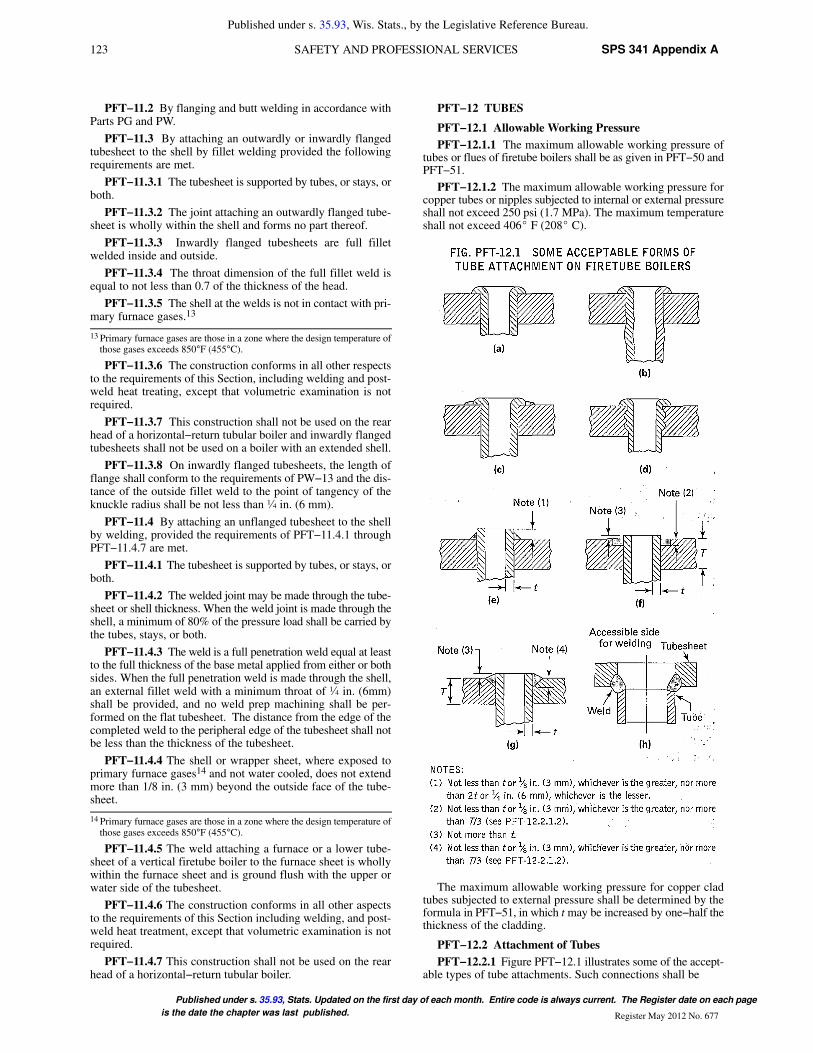
123 SPS 341 Appendix ASAFETY AND PROFESSIONAL SERVICES
Published under s. 35.93, Wis. Stats., by the Legislative Reference Bureau.
Published under s. 35.93, Stats. Updated on the first day of each month. Entire code is always current. The Register date on each page
is the date the chapter was last published. Register May 2012 No. 677
PFT−11.2 By flanging and butt welding in accordance withParts PG and PW.
PFT−11.3 By attaching an outwardly or inwardly flangedtubesheet to the shell by fillet welding provided the followingrequirements are met.
PFT−11.3.1 The tubesheet is supported by tubes, or stays, orboth.
PFT−11.3.2 The joint attaching an outwardly flanged tube-sheet is wholly within the shell and forms no part thereof.
PFT−11.3.3 Inwardly flanged tubesheets are full filletwelded inside and outside.
PFT−11.3.4 The throat dimension of the full fillet weld isequal to not less than 0.7 of the thickness of the head.
PFT−11.3.5 The shell at the welds is not in contact with pri-mary furnace gases.13
13 Primary furnace gases are those in a zone where the design temperature ofthose gases exceeds 850°F (455°C).
PFT−11.3.6 The construction conforms in all other respectsto the requirements of this Section, including welding and post-weld heat treating, except that volumetric examination is notrequired.
PFT−11.3.7 This construction shall not be used on the rearhead of a horizontal−return tubular boiler and inwardly flangedtubesheets shall not be used on a boiler with an extended shell.
PFT−11.3.8 On inwardly flanged tubesheets, the length offlange shall conform to the requirements of PW−13 and the dis-tance of the outside fillet weld to the point of tangency of theknuckle radius shall be not less than ¼ in. (6 mm).
PFT−11.4 By attaching an unflanged tubesheet to the shellby welding, provided the requirements of PFT−11.4.1 throughPFT−11.4.7 are met.
PFT−11.4.1 The tubesheet is supported by tubes, or stays, orboth.
PFT−11.4.2 The welded joint may be made through the tube-sheet or shell thickness. When the weld joint is made through theshell, a minimum of 80% of the pressure load shall be carried bythe tubes, stays, or both.
PFT−11.4.3 The weld is a full penetration weld equal at leastto the full thickness of the base metal applied from either or bothsides. When the full penetration weld is made through the shell,an external fillet weld with a minimum throat of ¼ in. (6mm)shall be provided, and no weld prep machining shall be per-formed on the flat tubesheet. The distance from the edge of thecompleted weld to the peripheral edge of the tubesheet shall notbe less than the thickness of the tubesheet.
PFT−11.4.4 The shell or wrapper sheet, where exposed toprimary furnace gases14 and not water cooled, does not extendmore than 1/8 in. (3 mm) beyond the outside face of the tube-sheet.
14 Primary furnace gases are those in a zone where the design temperature ofthose gases exceeds 850°F (455°C).
PFT−11.4.5 The weld attaching a furnace or a lower tube-sheet of a vertical firetube boiler to the furnace sheet is whollywithin the furnace sheet and is ground flush with the upper orwater side of the tubesheet.
PFT−11.4.6 The construction conforms in all other aspectsto the requirements of this Section including welding, and post-weld heat treatment, except that volumetric examination is notrequired.
PFT−11.4.7 This construction shall not be used on the rearhead of a horizontal−return tubular boiler.
PFT−12 TUBES
PFT−12.1 Allowable Working Pressure
PFT−12.1.1 The maximum allowable working pressure oftubes or flues of firetube boilers shall be as given in PFT−50 andPFT−51.
PFT−12.1.2 The maximum allowable working pressure forcopper tubes or nipples subjected to internal or external pressureshall not exceed 250 psi (1.7 MPa). The maximum temperatureshall not exceed 406� F (208� C).
The maximum allowable working pressure for copper cladtubes subjected to external pressure shall be determined by theformula in PFT−51, in which t may be increased by one−half thethickness of the cladding.
PFT−12.2 Attachment of Tubes
PFT−12.2.1 Figure PFT−12.1 illustrates some of the accept-able types of tube attachments. Such connections shall be
124SPS 341 Appendix A WISCONSIN ADMINISTRATIVE CODE
Published under s. 35.93, Wis. Stats., by the Legislative Reference Bureau.
Published under s. 35.93, Stats. Updated on the first day of each month. Entire code is always current. The Register date on each
page is the date the chapter was last published.Register Mary 2012 No. 677
(a) expanded and beaded as in illustrations (a), (b), and (d)
(b) expanded and beaded and seal welded as in illustration(c)
(c) expanded and seal welded as in illustration (e)
(d) welded, as in illustrations (f) and (g)
Tube ends attached by expanding and welding are subject tothe provisions specified in PFT−12.2.1.1 through PFT−12.2.1.3.
PFT−12.2.1.1 Where no bevel or recess is employed, thetube shall extend beyond the tubesheet not less than a distanceequal to the tube thickness or 1/8 in. (3 mm), whichever is thegreater, nor more than twice the tube thickness or ¼ in. (6 mm),whichever is the lesser [see Fig. PFT−12.1, illustration (e)].
PFT−12.2.1.2 The tubesheet hole may be beveled orrecessed. The depth of any bevel or recess shall not be less thanthe tube thickness or 1/8 in. (3 mm), whichever is greater, normore than one−third of the tubesheet thickness, except that whentube thicknesses are equal to or greater than 0.150 in. (4 mm),the bevel or recess may exceed T/3. Where the hole is beveledor recessed, the projection of the tube beyond the tubesheet shallnot exceed a distance equal to the tube wall thickness [see Fig.PFT−12.1, illustrations (f) and (g)].
PFT−12.2.1.3 On types of welded attachment shown in Fig.PFT−12.1, illustrations (c) and (e), the tubes shall be expandedbefore and after welding. On types shown in illustrations (f) and(g), the tubes may be expanded.
PFT−12.2.2 Expanding of tubes by the Prosser method maybe employed in combination with any beaded or seal weldedattachment method [see Fig. PFT−12.1, illustration (b)].
PFT−12.2.3 After seal welding as shown by Fig. PFT−12.1,illustrations (c) and (e), a single hydrostatic test of the boilershall suffice.
PFT−12.2.4 The inner surface of the tube hole in any formof attachment may be grooved or chamfered.
PFT−12.2.5 The sharp edges of tube holes shall be taken offon both sides of the plate with a file or other tool.
DOORS AND OPENINGS
PFT−40 WELDED DOOR OPENINGS
Arc or gas welding may be used in the fabrication of doorholes provided the sheets are stayed around the opening inaccordance with the requirements of PFT−27.6 and PFT−27.7.
No calculations need be made to determine the availability ofcompensation for door openings spanning between the plates ofwaterlegs. The required thickness of circular access openingsshall be determined in accordance with PFT−51. The requiredthickness of door openings of other than circular shape shall becalculated using eq. (1) of PG−46, using 2.1 or 2.2 for the valueof C, depending on the plate thickness, and a value of p equal tothe waterleg inside width. Volumetric examination of the join-ing welds is not required.
PFT−41 OPENINGS IN WRAPPER SHEETS
Openings located in the curved portion of the wrapper sheetof a locomotive type boiler shall be designed in accordance withthe rules in PG−32.
PFT−42 FIRESIDE ACCESS OPENINGS
The minimum size of an access or fire door opening, in whichthe minimum furnace dimension is 24 in. (600 mm), shall be notless than 12 in. x 16 in. (300 mm x 400 mm) or equivalent area,11 in. (280 mm) to be the least dimension in any case. A circularopening shall be not less than 15 in. (380 mm) in diameter.
For furnace dimensions less than 24 in. (600 mm), the open-ing should be 2 ¾ in. x 3 ½ in. (70 mm x 89 mm) or larger wherepossible. In cases where the size or shape of the boiler prohibitsan opening of that size, two openings with a minimum size of 1
in. (25 mm) may be used, preferably opposite each other, to per-mit inspection and cleaning of the furnace. If the burner isremovable so as to permit inspection and cleaning through theburner opening, a separate access opening need not be provided.
The bonnet or smoke hood of a vertical flue or tubular boilershall be provided with an access opening at least 6 in. x 8 in. (150mm x 200 mm) for the purpose of inspection and cleaning thetop head of the boiler.
PFT−43 REQUIREMENTS FOR INSPECTION OPENINGS
All firetube boilers shall have sufficient inspection openings,handholes, or washout plugs with a minimum of four openingsto permit inspection of the waterside of the tubesheets, furnaces,and tubes and to permit flushing of loose scale and sedimentfrom the boiler. Except where space restrictions would prohibitentry to the boiler, a manhole shall be provided in the upper por-tion of the shell. All openings shall meet the requirements ofPG−32 through PG−44. Where washout plugs are used, the min-imum size shall be NPS 1½ (DN 40), except for boilers 16 in.(400 mm) or less in inside diameter, the minimum size shall beNPS 1 (DN 25).
PFT−44 OPENING BETWEEN BOILER AND SAFETYVALVE
The opening or connection between the boiler and the safetyvalve shall have at least the area of the valve inlet.
After the boiler Manufacturer provides for the openingrequired by the Code, a bushing may be inserted in the openingin the shell to suit a pressure relief valve that will have the capac-ity to relieve all the steam that can be generated in the boiler andwhich will meet the Code requirements. The minimum size ofthe connection and opening for the pressure relief valve shall benot less than NPS ½ (DN 15).
No valve of any description shall be placed between therequired pressure relief valve or valves and the boiler, or on thedischarge pipe between the pressure relief valve and the atmo-sphere. When a discharge pipe is used, the cross−sectional areashall be not less than the full area of the valve outlet or of the totalof the areas of the valve outlets discharging thereinto and shallbe as short and straight as possible and so arranged as to avoidundue stresses on the valve or valves.
DOMES
PFT−45 REQUIREMENTS FOR DOMES
PFT−45.1 The longitudinal joint of a dome may be buttwelded or the dome may be made without a seam of one pieceof steel pressed into shape. The dome flange may be double fullfillet lap−welded to the shell if all welding complies fully withthe requirements for welding in Part PW. Volumetric examina-tion of the fillet welds may be omitted. The opening shall bereinforced in accordance with PG−32 through PG−44.
PFT−45.3 When a dome is located on the barrel of a locomo-tive−type boiler or on the shell of a horizontal−return tubularboiler, the outside diameter of the dome shall not exceed six−tenths the inside diameter of the shell or barrel of the boilerunless the portion of the barrel or shell under the dome (the neu-tral sheet) is stayed to the head or shell of the dome by stayswhich conform in spacing and size to the requirements given inPG−46 and Table 1A of Section II, Part D. With such stayed con-struction the outside diameter of a dome located on the barrel orshell of a boiler is limited to eight−tenths of the barrel or shellinside diameter.
PFT−45.4 All domes shall be so arranged that any water candrain back into the boiler.
PFT−45.5 Flanges of domes shall be formed with a cornerradius, measured on the inside, of at least twice the thickness ofthe plate for plates 1 in. (25 mm) in thickness or less, and at least

125 SPS 341 Appendix ASAFETY AND PROFESSIONAL SERVICES
Published under s. 35.93, Wis. Stats., by the Legislative Reference Bureau.
Published under s. 35.93, Stats. Updated on the first day of each month. Entire code is always current. The Register date on each page
is the date the chapter was last published. Register May 2012 No. 677
three times the thickness of the plate for plates over 1 in. (25 mm)in thickness.
PFT−45.6 Domes and manhole frames attached to shells orheads of boilers shall be designed in accordance with PG−32through PG−44.
PART PEB
REQUIREMENTS FOR ELECTRIC BOILERS
GENERAL
PEB−1 GENERAL
The rules in Part PEB are applicable to electric boilers andparts thereof and shall be used in conjunction with the generalrequirements in Part PG as well as with the special requirementsin the applicable Parts of this Section that apply to the methodof fabrication used.
PEB−2 SCOPE
PEB−2.1 This part contains special rules for construction ofelectric boilers, both of the electrode and immersion resistanceelement type. This Part does not include electric boilers wherethe heat is applied externally to the boiler pressure vessel byelectric resistance heating elements, induction coils, or otherelectrical means. These types of electric boilers shall be con-structed in accordance with other applicable Parts of this Sec-tion.
PEB−2.2 Electric boilers and parts thereof that do not exceedthe diameter, volume, or pressure limits of PMB−2 may be con-structed using the applicable paragraphs of Part PMB in con-junction with this Part.
PEB−2.3 An electrode type boiler is defined as an electricboiler in which heat is generated by the passage of an electriccurrent using water as the conductor.
PEB−2.4 An immersion resistance element type boiler isdefined as an electric boiler in which heat is generated by thepassage of an electric current through a resistance heating ele-ment directly immersed in water, or enclosed in a pipe immersedin water.
PEB−2.5 Electric boilers may be field assembled providedthe boiler is manufactured and assembled in compliance with theprovisions and requirements of Part PEB and other applicableParts of this Section.
PEB−3 OPTIONAL REQUIREMENTS FOR THEBOILER PRESSURE VESSEL
The boiler pressure vessel may be constructed in compliancewith the ASME Pressure Vessel Code Section VIII, Division 1,rules for unfired steam boilers [UW−2(c)] subject to the condi-tions specified in PEB−3.1 through PEB−3.4.
PEB−3.1 The Manufacturer who certifies and stamps thecompleted boiler shall specify to the “U” stamp holder all addi-tional requirements of Part PEB, which are not requirements ofSection VIII, Division 1, and shall ensure that these require-ments are satisfied.
PEB−3.2 These additional requirements are:
PEB−3.2.1 The materials of construction shall comply withthe requirements of PEB−5.1 and PEB−5.3.
PEB−3.2.2 Inspection openings shall comply with therequirements of PEB−10.
PEB−3.3 The boiler pressure vessel shall be stamped withthe ASME Code “U” symbol and the letters “UB,” and be docu-mented with the ASME U−1 or U−1A Data Report.
PEB−3.4 The master Data Report P−2A for the ElectricBoiler shall indicate “Boiler pressure vessel constructed to Sec-tion VIII, Division 1 as permitted by Part PEB.”
MATERIALS
PEB−5 GENERAL
PEB−5.1 Unless specifically permitted elsewhere in this sec-tion, materials used in the construction of pressure parts for elec-tric boilers shall conform to one of the specifications in SectionII and shall be limited to those permitted by PG−6, PG−7, PG−8,and PG−9 for which allowable stress values are given in Tables1A and 1B of Section II, Part D. Miscellaneous pressure partsshall conform to the requirements of PG−11.
PEB−5.2 Seamless or welded shells, plates, or heads of elec-tric boilers shall not be less than 3/16 in. (5 mm) in thickness.
PEB−5.3 Electric boilers of the immersion element type maybe fabricated of austenitic stainless steel type 304, 304L, 316,316L, and 347 of any material specification listed in PG−6 andPG−9, provided that a precautionary statement indicating thatthe boiler shall be operated using only deionized water, havinga maximum conductance of 1 microSiemen per cm (1 µS/cm)[minimum specific resistivity of 1 megohm per cm (1 M¿/cm)],is clearly marked on the boiler in a visible location.
DESIGN
PEB−8 GENERAL
PEB−8.1 The rules in the following paragraphs apply specif-ically to the design of electric boilers and parts thereof. Theyshall be used in conjunction with the general requirements fordesign in Part PG, any applicable requirements in Part PMB forminiature boilers, and with the specific requirements for designin applicable Parts of this Section that apply to the method of fab-rication used.
PEB−8.2 Responsibility of design of electric boilers to bemarked with the “E” symbol shall be that of the holder of the “E”stamp.
PEB−9 WELDING
Electric boilers may be constructed by fusion welding inaccordance with all the requirements of this Section except thatpostweld heat treatment, volumetric examination of the weldedjoints, and the nondestructive examinations described inPG−93.1 are not required when the limitations in PMB−2.1 arenot exceeded.
PEB−10 INSPECTION OPENINGS
PEB−10.1 Electric boilers of a design employing a remov-able cover, or removable internal electric heating elements thatwill permit access for inspection, and cleaning and having aninternal volume (exclusive of casing and insulation) of not morethan 5 ft3 (0.14 m3) need not be fitted with washout or inspectionopenings.
PEB−10.2 Electric boilers of more than 5 ft3 (0.14 m3) notprovided with a manhole, shall have an inspection opening orhandhole located in the lower portion of the shell or head. Theinspection opening shall not be smaller than NPS 3 (DN 80). Inaddition, electric boilers of the resistance heating element typedesigned for steam service shall have an inspection opening orhandhole at or near the normal waterline.
PEB−11 FEEDWATER SUPPLY
PEB−11.1 The feedwater source to electric boilers shall becapable of meeting the applicable requirements of PG−61. Feed-water connections to an electric boiler shall not be smaller thanNPS ½ (DN 15), except as permitted by PMB−11.
PEB−11.2 Electric boilers that do not exceed the diameter,volume, or pressure limits of PMB−2, may have the feedwaterdelivered through the blowoff opening if desired.
PEB−12 BLOWOFF
PEB−12.1 The blowoff piping for each electric boiler pres-sure vessel having a normal water content not exceeding 100 gal(380 L) is required to extend through only one valve.
126SPS 341 Appendix A WISCONSIN ADMINISTRATIVE CODE
Published under s. 35.93, Wis. Stats., by the Legislative Reference Bureau.
Published under s. 35.93, Stats. Updated on the first day of each month. Entire code is always current. The Register date on each
page is the date the chapter was last published.Register Mary 2012 No. 677
PEB−12.2 The minimum size of blowoff pipes and fittingsshall be NPS 1 (DN 25), except that for boilers of 200 kW inputor less the minimum size of pipe and fittings may be NPS ¾ (DN20). Electric boilers that do not exceed the diameter, volume, orpressure limits of PMB−2 may have blowoff connections inaccordance with PMB−12.
PEB−13 WATER LEVEL INDICATORS
PEB−13.1 Electric boilers of the electrode type shall have atleast one gage glass. The gage glass shall be located as to indi-cate the water levels both at startup and under maximum steamload conditions as established by the Manufacturer.
PEB−13.2 Electric boilers of the resistance element typeshall have at least one gage glass. The lowest visible water levelin the gage glass shall be at least 1 in. (25 mm) above the lowestpermissible water level as determined by the Manufacturer.Each electric boiler of this type shall also be equipped with anautomatic low−water cutoff on each boiler pressure vessel solocated as to automatically cut off the power supply to the heat-ing elements before the surface of the water falls below the vis-ible level in the gage glass.
PEB−13.3 Tubular gage glasses on electric boilers shall beequipped with protective rods or shields.
PEB−14 PRESSURE GAGES
Pressure gages shall meet the requirements of PG−60.6.
PEB−15 PRESSURE RELIEF VALVES
PEB−15.1 Each electric boiler shall have at least one pres-sure relief valve. Electric boilers with a power input more than1,100 kW shall have two or more pressure relief valves.
PEB−15.2 The minimum pressure relief valve relievingcapacity for electric boilers shall be 3 ½ lb/hr/kW (1.6 kg/hr/kW) input. The pressure setting shall not be higher than theMAWP stamped on the completed boiler (see PEB−18.3.2).
PEB−15.3 Pressure relief valves shall be mounted in accord-ance with PG−71.2 with the spindle vertical. Electric boilers thatdo not exceed the diameter, volume, or pressure limits ofPMB−2, may have a pressure relief valve(s) installed in otherthan the vertical position, provided that
(a) the valve design is satisfactory for such position
(b) the valve is not larger than NPS ¾ (DN 20)
(c) the maximum angle of deviation from vertical does notexceed 30 deg
(d) the nozzle location is such that no material that couldinterfere with the operation of the valve can accumulate at thevalve inlet
(e) the discharge opening of the valve body and dischargepiping is oriented so that drainage is adequate
PEB−16 AUTOMATIC DEVICES
Electric boilers shall be provided with pressure and/or tem-perature controls and an automatic low−water fuel cutoff. Nolow−water cutoff is required for electrode type boilers.
PEB−17 HYDROSTATIC TEST
PEB−17.1 Each electric boiler pressure vessel shall behydrostatically tested at completion of fabrication in accordancewith PG−99 or PMB−21, as applicable.
PEB−17.2 In addition to the above, after assembly of theboiler pressure vessel and the mechanically assembled boilerexternal piping and trim, the completed electric boiler shall begiven a final hydrostatic test at a pressure not less than 1 ½ timesthe MAWP of the pressure vessel. Miniature electric boilers thatare trimmed to operate at less than the MAWP of the pressurevessel shall be given a hydrostatic test at a pressure not less thanthe safety valve setting.
PEB−17.3 When the electric boiler is to be marked with the“E” symbol, the symbol shall be applied after completion of thehydrostatic test of PEB−17.2.
PEB−18 INSPECTION AND STAMPING OF BOILERS
PEB−18.1 Inspection of electric boilers shall be as requiredby PG−90.1 and PG−90.3. Witness by the Authorized Inspectorof the hydrotest required in PEB−17.2 for the completed boilermay be omitted for electric boilers that meet all the followinglimitations:
(a) 800 kW maximum per vessel
(b) 600 V maximum
(c) mechanically assembled boiler external piping (BEP)only
When the Authorized Inspector does not perform a finalinspection of the completed boiler, the Manufacturer or Assem-bler shall make an equivalent examination. The equivalentexamination shall be in accordance with a quality control proce-dure meeting the requirements of PEB−18.2 and PEB−18.5.
PEB−18.1.1 Electric boilers exceeding the size limitationsspecified in PEB−18.1, and having only mechanically assem-bled external piping (BEP) and trim, shall have a final inspectionby the Authorized Inspector, who shall also witness the hydro-static test called for in PEB−17.2.
PEB−18.1.2 For electric boilers having welded or brazedboiler external piping (BEP) or trim, the inspection require-ments of PG−90.1 and the hydrostatic test requirements ofPG−99 apply.
PEB−18.2 Each electric boiler Manufacturer shall complywith the applicable requirements of PG−104 and PG−105.
PEB−18.2.1 An electric boiler Manufacturer or Assemblerapplying for or renewing the “E” stamp shall have its facilitiesand organizations subject to a joint review by its AuthorizedInspection Agency and the legal jurisdiction involved (see lastparagraph of PG−105.4).
PEB−18.2.2 A Manufacturer or Assembler holding an “E”stamp and assembling units where the final shop inspection isnot mandatory (see PEB−18.1), shall be subject to periodicreview by its Authorized Inspection Agency. The review shallbe conducted on a quarterly basis or more frequently if deemednecessary by the Authorized Inspection Agency. The frequencyof this review may be reduced subject to written agreementbetween the Manufacturer or Assembler and its inspectionagency and the written approval of the appropriate legal jurisdic-tion. However, in no case shall the review be less than onceevery 6 months.
PEB−18.3 The stamping of electric boilers shall conform tothe requirements of PG−106. Completed electric boilers shall bemarked with the “S” or “M” symbol by the Manufacturer of theboiler pressure vessel except when the boiler pressure vessel isconstructed under the provisions of PEB−3 (see PEB−18.4).When the trim, fixtures and fittings (such as valves), threadedboiler external piping, and appurtenances are connected to anelectric boiler by a Manufacturer or Assembler not authorizedto apply the “S” or “M” stamp, the boiler assembler shall applyan “E” stamp to the completed assembly. “E” stamp holders arelimited to the use of assembly methods that do not require weld-ing or brazing.
PEB−18.3.1 The stamping of the boiler pressure vessel shallbe located as called for in PG−111.8 and need not indicate thekW input or the maximum designed steaming capacity.
PEB−18.3.2 The stamping of the complete electric boilershall be on a separate metallic plate and shall be in accordancewith PG−106.4. The MAWP shall be that established by thecompleted boiler assembler holding the “S,” “M,” or “E” stamp,but in no case higher than the MAWP stamped on the boiler
127 SPS 341 Appendix ASAFETY AND PROFESSIONAL SERVICES
Published under s. 35.93, Wis. Stats., by the Legislative Reference Bureau.
Published under s. 35.93, Stats. Updated on the first day of each month. Entire code is always current. The Register date on each page
is the date the chapter was last published. Register May 2012 No. 677
shell. The MAWP shall be listed on Part II of Form P−2A, Manu-facturers’ Data Report for All Types of Electric Boilers. Thisplate shall be located on the assembly so that it is readily visiblefrom the operating floor.
PEB−18.3.3 The stamping required by PEB−18.3.2 need notbe done in the presence of the Authorized Inspector for electricboilers that do not receive final inspection by the AuthorizedInspector (see PEB−18.1).
PEB−18.4 For boiler pressure vessels constructed under theprovisions of PEB−3, the inspection and stamping requirementsof Section VIII, Division 1, UG−116(c) for special service pres-sure vessels (UB), shall be followed.
PEB−18.5 Those Manufacturers and Assemblers providingan equivalent examination of completed electric boilers whenfinal inspection is not witnessed by the Authorized Inspector(see PEB−18.1), shall provide oversight by a Certified Individ-ual (CI).
PEB−18.5.1 A Certified Individual (CI) shall be anemployee of the Manufacturer or Assembler and shall be quali-fied and certified by the Manufacturer or Assembler. Qualifica-tions shall include as a minimum
(a) knowledge of the requirements of this Section for theapplication of Code symbols
(b) knowledge of the Manufacturer’s quality program
(c) training commensurate with the scope, complexity, orspecial nature of the activities to which oversight is to be pro-vided
The Manufacturer or Assembler shall maintain a record con-taining objective evidence of the Certified Individual’s qual-ifications, training and certification.
PEB−18.5.2 The duties of a Certified Individual (CI) shallbe to assure that each use of the Code symbol as permitted inPEB−18.3.3 is in accordance with the requirements of this Sec-tion and is documented on the Certificate of Conformance onForm P−2A, Manufacturers’ Data Report for All Types of Elec-tric Boilers. The CI shall also
(a) verify that each electric boiler, to which a Code symbolis applied, meets all applicable requirements of this Section
(b) sign the Certificate of Conformance, Form P−2A, priorto release of control of the boiler
PEB−19 MANUFACTURERS’ DATA REPORT FORELECTRIC BOILERS
PEB−19.1 This form consists of two parts. Part I is to be com-pleted by the Manufacturer of the boiler pressure vessel who isthe holder of the “S” or “M” stamp and his inspection agency.Part II is to be completed by the Manufacturer or Assemblerresponsible for the completed electric boiler who shall be autho-rized to use any of the “S,” “M,” or “E” stamps.
PEB−19.2 When the boiler pressure vessel is constructed bya “U” stamp holder and certified on a U−1 or U−1A Data Report,Part 1 shall be completed by the “S,” “M,” or “E” stamp holderto the extent indicated in Guide A−351.1.