Embed Size (px)
Citation preview
TRC us
r,cr-nRns CENTER REGION 5
478877
EXCAVATION WORK PLAN ((VuU ouw.-, "BV, d V £ )
Dover Chemical Corporation Dover, Ohio
Prepared for: Dover Chemical Corporation
3676 Davis Road N.W. Dover, Ohio
Prepared by: TRC Environmental Corporation
Boott Mills South 116 John Street
Lowell, Massachusetts
fRC Project No.: 41768-0010
July 2006
EXCAVATION WORK PLAN
Dover Chemical Corporation Dover, Ohio
Prepared for: Dover Chemical Corporation
3676 Davis Road N.W. Dover, Ohio
Prepared by: TRC Environmental Corporation
Boott Mills South 116 John Street
Lowell, Massachusetts
TRC Project No.: 41768-0010
July 2006
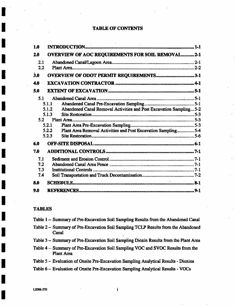
TABLE OF CONTENTS
1.0 INTRODUCTION...
2.0 OVERVIEW OF AOC REQUIREMENTS FOR SOIL REMOVAL 2-1
2.1 Abandoned Canal/Lagoon Area 2-1 2.2 Plant Area .....2-2
3.0 OVERVIEW OF ODOT PERMIT REQUIREMENTS 3-1
4.0 EXCAVATION CONTRACTOR 4-1 5.0 EXTENT OF EXCAVATION 5-1
5.1 Abandoned Canal Area ....^....5-1 5.1.1 Abandoned Canal Pre-Excavation Sampling 5-1 5.1.2 Abandoned Canal Removal Activities and Post Excavation Sampling... 5-2 5.1.3 Site Restoration 5-3
5.2 Plant Area 5-3 5.2.1 Plant Area Pre-^Excavation Sampling 5-3 5.2.2 Plant Area Removal Activities and Post Excavation Sampling 5-4 5.2.3 Site Restoration 5-6
6.0 OFF-SITE DISPOSAL 6-1
7.0 ADDITIONAL CONTROLS 7-1
7.1 Sediment and Erosion Control 7-1 7.2 Abandoned Canal Area Fence 7-1 7.3 Institutional Controls 7-1 7.4 Soil Transportation and Truck Decontamination 7-2
8.0 SCHEDULE ..... 8-1
9.0 REFERENCES .... ..... ......................... ... 9-1
TABLES
Table 1 - Summary of Pre-Excavation Soil Sanipling Results from the Abandoned Canal
Table 2 - Summary of Pre-Excavation Soil Sampling TCLP Results from the Abandoned Canal
Table 3 - Summary of Pre-Excavation Soil Sampling Dioxin Residts from the Plant Area
Table 4 - Summary of Pre-Excavation Soil Sampling VOC and SVOC Results from the Plant Area
Table 5 - Evaluation of Onsite Pre-Excavation Sampling Analytical Results - Dioxins
Table 6 - Evaluation of Onsite Pre-Excavation Sampling Analytical Results - VOCs
L2006-270
FIGURES
Figure 1 - Abandoned Canal Proposed Excavation Areas Map
Figure 2 - Plant Area Proposed Excavation Areas Map
Figure 3 - Schedule for Implementation of Soil Removal Actions at the Abandoned Canal and jPlant Areas C, F, and B V.
ATTACHMENTS
Attachment A - EPA Letter Dated October, 2005 Regarding Modification of the AOC dated October 20^ 2000 - Lagoon Area and Canal Soils/Sediment and Plant Area Soil
Attachment B - Pre-excavation Analytical Sampling Results
Attachment C - Data Validation Reports
Attachment D - Amendment to the Health and Safety Plan (HASP)
Attachment E - Ohio DOT Permit
Attachment F - Amendment to the Quality Assurance Plan (QAPP)
Attachment G - October 4,2005 Email Message from EPA Regarding Pre-Excavation Sampling at Onsite Areas C, E and BY
L2006-270
1.0 INTRODUCTION
This work plan describes the actions that will be taken, as required by the Administrative Order by Consent (AOC), to remediate the Lagoon/Canal Area soils along with soils in Plant Areas BV, C, and E. Dover Chemical has retained TRC Environmental Corporation to assist with the actions described in this excavation plan. The format of this document follows that required per the United States Environmental Protection Agency (EPA) letter dated October 6, 2005. The letter is included as Attachment A. All site work shall be conducted in accordance with the Health and Safety Plan (HASP) (Framatome, 2003) and the Quality Assurance Plan (QAPP) (Framatome, 2003). Amendments to the HASP and QAPP, which address specific tasks associated with this work, are provided as Attachments D and F. All sampling work shall be conducted in accordance with the Field Sampling Plan (FSP) (Framatome, 2003).
The Dover Chemical site is located in Tuscawaras County in east central Ohio. The site is approximately 60 acres and consists of a main plant area east of Interstate 77 (1-77) along with a parcel west of 1-77 which includes an Abandoned Canal/Lagoon area and a wooded low lying area which require certain remedial activities pursuant to the AOC. Land use around the facility is varied and includes industrial, commercial, and residential areas. Industrial facilities are located to the north and south. Several blocks of residences are located east of the site and extend to the north and south.
Dover Chemical Corporation was incorporated in 1951 and was acquired by ICC Industries in 1975. The facility currently produces organic phosphites and chlorinated paraffin products. The chlorinated paraffin products are used in the manufacture of pressure lubricants, plasticizers, and flame retardants for vinyl products and the organic phosphites are used as antioxidants in the polyolefin industry. Over the 1950s to the early 1970s, site activities introduced site-related constituents into the environment through the deposition of dichlorobenzene in a low lying area in the southwestern comer of the facility, the temporary storage of hexachlorocyclohexane (BHC) on the ground next to Building 21, and unintentional process spills and leaks. Soils contamination was found during the Remedial Investigation/Feasibility Study (Rl/FS) in 1991. Plant area soils contained polychlorinated dibenzodioxins (PCDDs), dibenzofurans (PCDFs), chlorobenzenes, carbon tetrachloride, and hexachlorobenzene (HCB). Lagoon area soils contained PCDDs and PCDFs. Abandoned Canal Area soils contained PCDDs, PCDFs, chlorobenzene, 1,3-dichlorobenzene, 1,2,4-trichlorobenzene andHCB. Dover and the EPA entered into an Administrative Order by Consent, Docket No. V-W-Ol-C-619 (AOC) to mitigate a direct contact risk to workers from the contaminated soils.
L2006-270 1-1
2.0 OVERVIEW OF AOC REQUIREMENTS FOR SOIL REMOVAL
All work will be performed in accordance with all applicable federal and state regulatory lequiiements. A summary of the requirements for remediation of the Lagoon/Canal area and Subject Plant areas as specified in the AOC follows.
2.1 Abandoned Canal/Lagoon Area
The following non-time critical removal actions will be performed during the excavation of Canal area soils:
• The areas that contain contaminated soils/sediments that exceed the ecological screening level for dioxin will be excavated up to a maximum removal depth of 3 feet for the first 50 feet of the old canal (beginning from the historical point where wastewater entered the canal) and 1 foot along the test of the canal area requiring excavation.
• The top 1 foot of soil over the 4,400 square foot area identified from samples collected after the feasibility study was developed will be removed. Any areas that are excavated shall be backfilled and returned to pre-excavation grade.
• In the areas where removal of dioxin contaminated soil stops at a maximum depth, the soil/sediment will be sampled and analyzed in order to document the levels of dioxin contamination which will be left in place. No additional soil/sediment removal will be performed regardless of the findings from soil analysis.
• If the concentration of dioxin in the soils below the maximum depth remains above the ecological screening level, a marker, such as an orange polyethylene netting, will be laid on top of the soil/sediment at this depth in order to make it clear to anyone, excavating in these areas that these soils are not to be disturbed. The area will then be backfilled to present grade to prevent erosion and institutional controls will be implemented to maintain the cover.
• The excavated soil/sediment will be treated as needed to meet off-site disposal requirements, including land disposal restrictions. The material will be transported to an off-site approved landfill that is acceptable under the off-site mle.
• Backfilled areas will receive seed and be re-vegetated.
• A fence barrier will be installed around the Lagoon area.
L2006-270 2-1
• "No Fishing" and "No Trespassing" signs are already posted at all access points around the Lagoon Area. The signs will continue to be actively naaintained and replaced as needed-
• Following excavation, the barrier and signs will be regularly nionitoted and maintained. Areas of soil erosion will be repaired as it occurs.
2.2 Plant Area
The following nOn^time critical removal actions will be performed for the excavation of Plant areas B V, C, and E:
• The areas exceeding the action level (5 ppb (TEQs) dioxin) for dioxin-contaminated soils in the Plant area, will be excavated. The maximum depth of excavation is controlled by a typical industrial building foundation depth of up to 4 feet.
• All excavated and stpclq)iled soil and materials will be disposed of off-site in an approved landfill that is acceptable under the NCP's off-site mle. Excavated and stockpiled soil and materials will be treated as necessary to meet off-site disposal requirements, including land disposal restrictions.
• In the areas where removal of dioxin-containinated soil stops at a depth of 4 feet, the soil will be sampled and analyzed in order to document the levels of dioxin contamination which will be left in place. No additional soil removal will be performed regardless of the findings from soil analysis.
• If the concentration of dioxin in the soils below 4 feet remains above the action level of 5 ppb, a marker, such as an orange polyethylene netting, will be laid on top of the soil at this depth in order to make it clear to anyone excavating in these areas that these soils are not to be disturbed. The area will then be backfilled with clean Soil to present grade and designed with consideration for future site use and the prevention of soil erosion. A restriction will be placed on the property deed to restrict excavation below a depth of 4 feet. Institutional controls will also be instituted to ensure that the integrity of the covers is maintained.
• The excavated areas will be backfilled with imported clean soil.
12006-270 2-2
3.0 OVERVIEW OF ODOT PERMIT REQUIREMENTS
A permit (No, 11-2006-0138) to gain access to the Canal area from 1-77 was issued by the Ohio Deparbnent of Transportation (ODOT) on November 11,2005. DoverYTRG Environmental plws to construct a temporary access road off southbound Exit 83, DoveiASugar Creek. The temporary access road will be constructed of filter fabric and #2 stone and will be installed by die excavation contractor.
DoverVTRC Environmental will work with Area Wide Protective of AkrOn, Ohio or a similar local vendor to implement all necessary traffic Controls and requirements as outlined in the permit. The following permit requirements shall be implemented during the excavation of soils from the Canal area:
• Working hours restricted to 9 AM to 3 PM. All ramp and deceleration restrictions must be removed by 3 PM daily. Work is prohibited during inclement weather such as fog, rain, or snow and ice conditions.
• An electronic message board must be set up 1 nule in advance of work zone notifying travelers of Shoulder Work Ahead - Trucks entering and exiting highway - Use ramp with Caution.
• A uniformed patrolman with a car with flashing lights will be used to control trucks re-entering on the ramp/deceleration lane during working hours.
• All dirt, gravel, or debris must be removed from the traveled portion of the roadway hourly.
• All damage to the roadway and right of way must be restored to like or better condition.
• A physical fence barrier must be in place during all non-working hours.
• No more than 2 trucks may be held in the Rest Area at one time.
• All trucks must leave the traveled lane and slow on the paved berm prior to leaving the roadway so that they do not inhibit traffic speed.
• All traffic controls depicted on the attached plan sheet are the responsibility of the permittee for placement and management.
• All barrels and cones must be kept in a clean condition to promote their reflectibility.
• All tmcks must use the interchanges for entry onto 1-77. Use of cross-overs is prohibited.
L2006-270 3-1
upon completion of the excavation woiic adjacent to 1^77, the temporary access road shall be removed and the area will be restored to pre-excavation conditions^
L2006.270 3-2
4.0 EXCAVATION CONTRACTOR
The excavation contractor will be Ronald Quinlan Excavation, 1647 State Route 39 NW, Dover, OH. Excavation personnel possess the appropriate OSHA HAZWOPPR Training and have performed similar remedial excavation for Dover chemical in the past.
L2006^270 4-1
5.0 EXTENT OF EXCAVATION
Pre^excavation soil samples have heen collected from both the Abandoned Canal and Plant Areas C, E and BV in accordance with the approved RADWP CFramatone, 2003). The pre-excavation soil samples were collected from the Abandoned Canal in July 2004. These samples were collected to support a determination as to whether VOC concentrations in the materials to be excavated could be sufficient to impact disposal requirements. Pre-excavation soil samples were collected from Plant Areas C, E and BV to support determination of required excavation depths prior to mobilization for implementation of the remedial actions. The following discussion presents the results of these sampling and analysis activities.
5.1 Abandoned Canal Area
5.1.1 Abandoned Canal Pre-Excavation Sampling
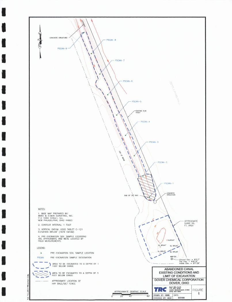
Figure 1 provides a map of the Abandoned Canal area that indicates the proposed areas of excavation along with the proposed depths of excavation as required in Ae AOC. The results of the pre-excavation sampling, resubmitted in a letter to the EPA dated September 6,2005, are included as Table 1 and Table 2 of this Excavation Plan. Table 1 presents the detected analytical results for the volatile organic compound (VOC) analyses. Table 2 presents the detected analytical results of Toxicity Characteristic Leaching Procedure (TCLP) testing performed on the two samples with the highest VOC concentrations. As shown in Table 2, no exceedances of the criteria for identifying a characteristic waste based on the TCLP testing were encountered. Using the areas and depths shown in Figure 1, the estimated volume of material requiring excavation is 650 cubic yards.
Sample nomenclature in Tables 1 and 2 follows that specified in Section 7.1 of the approved field sampling plan (Framatome, 2003). Each sample designation consists of an alpha^numeric sequence starting with the identification of the sample type and location. For those samples identified in Tables 1 and 2, this includes a "PS" for pre-excavation sample and "CAN" for canal. This is then followed by the soil boring number (i.e., 1 through 0) and the sample depth sequence (i.e., 6 to 12 inches below grade is number 1 in the depth sequence, 12 to 18 inches below grade is number 2 in the depth sequence, etc.). The third number in the sample identification provides additional detail on the sample type (i.e., a number 1 identifies an environmental sample, a number 2 identifies a duplicate sample). Any samples which have a "DL" in the s^ple identification are those which the laboratory had to re-run at a secondary dilution factor. For the samples presented in Table 2, the "CLP" notes these samples were submitted to the laboratory for toxicity characteristic leaching procedure testing.
Section 3.4.2 of the Response Action Design Work Plan (RADWP) states that prior to excavation, a composite sample of materials to be excavated and disposed will be collected from the 0-1 foot depth interval along the canal. This sample will be submitted to the offsite laboratory for TCLP lindane analysis. This sample will he collected at the
L2006^270 5-1
beginning of excavation activities at the Plant Areas: This will allow sufticient time for receipt of the analytical results prior to mobilization to the Abandoned Canal.
5.1.2 Abandoned Canal Removal Activities and Post Excavation Sampling
As required in the AOC, materials will be removed to a depth of 3 feet over the first 50 linear feet of the Abandoned Canal, north of the discharge structure. The remainder of the Abandoned Canal to be excavated, as identified in Figure 1, will be excavated to a depth of 1 foot. Beyond the limits of the Abandoned Cmial, to the south, the area identified in the AOC as the 4,400 square foot area, will be excavated to a depth of 1 foot. All materials removed from the areas identified on Figure 1 will be disposed of at the offsite facility identified in Section 6.0 of this Excavation Plan.
Upon reaching the excavation depth, confirmatory soil samples will be collected from the bottom of the excavation. This sample will be submitted to the offsite laboratory for chemical analysis. Results of these analyses will be used to document contaminant concentrations which remain at depth within the footprint of the excavation. Confirmatory samples collected for VOC analyses will be collected as discrete samples from the nine locations within the can^ where samples were collected from during the pre-excavation sampling conducted during the summer of 2004.
Also, composite soil samples will be collected from the areas to be excavated. A total of three coniposite soil samples will be submitted to the laboratory for dioxin analysis: one from the first 50 feet of the canal, one from the remainder of the canal footprint to be excavated and one from the 4,400 square foot area. The composite sample collected ft^om the first 50 ft of the canal will include equal aliquots of soil from the two sample locations located within this area in 2004 (identified in Figure 1 as PSCAN-1 and PSCAN-2). An additional TCLP sample will be collected from the vicinity of PSCAN-2-5-2. The TCLP extract will be analyzed using detection limits lower than the Maximum Contaminant Levels (MCLs). The composite sample from the remainder of the canal will consist of equal aliquots collected from the remaining 7 sample locations included in the 2004 pre-excavation effort (identified in Figure 1 as PSCAN-3 through PSCAN-9). The 4^400 sq ft area will be divided into 4 quadrants. Equal soil aliquots from the center of each of these quadrants will be collect^ and includ^ in a composite sample. At any location where confirmatory sample analytical results show contaminant concentrations remain above applicable criteria, a non-biodegradable hazard marker such as orange polyethylene netting will be placed at the excavation bottom prior to backfilling.
During the conduct of the removal actions at the Abandoned Canal area, dewatering activities may be required. Subsequent to submittal of this Excavation Plan, a Dewatering Plan will be submitted to EPA for review. The Dewatering Plan shall be submitted to EPA prior to initiation of excavation activities at the Abandoned Canal area.
L2006-270 S-2
5.1.3 Site Restoration
Once all requited materials have been removed and analytical data is obtained for conrirmation samples, the excavated areas will be backfilled to pie-excavation grades, as documented in Figute 1. hiitially, materials used to build the temporary access road off of the paved area of Interstate 77 will be used to backfill the excavations^ After the roadbed' materials have been expended, the balance of the backfill materials at the Abandoned Canal area will consist of stoclq)iled loam materials presently stored on the Dover facility. A representative composite sample of the loam material will be collected and analyzed for Target Compound List (TCL) VOCs, SVOCSj and Target Analyte List (TAL) metals to demonstrate the material is not contaminated.
After all excavations have been backfilled to pre-excaVation grades, the area will be hydroseeded. The hydroseeding will provide temporary stabilization against erosion of exposed soil surfaces until vegetation establishes. In accordance with the ODOT permit requirements, the area within the ODOT right-of-way will have to be restored to the satisfaction of the onsite ODOT representative. This will include removal of all remaining features associated with the removal action, re-construction of the fence and hydroseeding of disturbed areas within the right-of-way.
5.2 Plant Area
5.2.1 Plant Area Pre-Excavation Sampling
Table 3 presents a summary of the dioxin analytical results for the same samples. Concentrations which exceed the dioxin action level of 5 parts per billion (ppb) TEQ are shown in bold in Table 3. Table 4 presents a summary of the VOC and SVOC analytical results for the soil samples collected fixjm Plant Areas C, E and BV. In addition to the contaminant concentrations. Table 4 also identifies the associated Total Risk ratio for each depth interval within in each sample ^d based on the calculation described in Section 3.2 of the approved RADWP, using the following equation:
cone . cone- ^ , „ . — + — + = Total _ Risk _ Ratio
PRG^ PRGg
where:
cpncx = the soil concentration for contaminant X;
PRGx = Preliminary Remediation Goal for contaniinant X, provided in Table 3.1 of the Response Action Design Work Plan prepared by Framatome ANP (July 2003).
As stated in the approved RADWP, when the Total Risk Ratio exceeds 1, the soil must be excavated. As shown in Table 4, none of the sample results had a risk ratio greater than 1 below the 0 to 1 foot depth interval. Table 3 shows that there were exceedances for
U006-270 5-3
^oxin in the 0 to 1 foot depth interval, die 1 to 2 foot depth interval, and the 2 to 3 foot depth intervtd. Based on the review of these two tables it is clear that the depth of excavation is dictated by dioxin concentrations. Additionally, it is noted that Plant Area BV requires excavation to a depth of 3 feet below grade. However, the maximum depth of excavation in the other areas is 2 feet below grade or less. Within Plant Area E, grids 3 and 5 do not require excavation based on the absence of any exceedances of applicable action levels.
5.2.2 Plant Area Removal Activities and Post Excavation Sampling
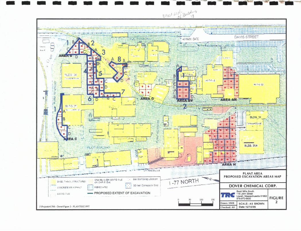
Figure 2 provides a map of the Plant areas B V, C and E that indicates the planned areas of excavation along wiA the proposed depths of excavation. Attachment B provides the laboratory analytical results for the pre-excavation soil characterization conducted in July, 2005. Tables 5 and 6 present Ae validated analytical results of the bottom of excavation samples as required in the Quality Assurance Project Plan (QAPP). Attachment C provides copies of the data validation reports for the sample results presented in Tables 5 and 6.
Similar to Tables 1 and 2, the sample nomeiiclature presented in Tables 5 and 6 are as specified in Section 7.1 of the approved FSP. In addition to the description of this nomenclature provided in Section 5.1.1 of this plan, the nomenclature in Tables 5 and 6 includes additional detail on the type of sample. The additional letters "CV" identify a composite VOC sample; "CSV" identiEes a composite semi-volatile organic compound sample and "CD" identifies a composite dioxin sample.
Within certain areas to be excavated, access issues exist due to the presence of utilities or structures, as documented in EPA's October 4,2005 email (provid^ as Attachment G). The specific issues are summarized below:
Area E
Grid E8. Borings a through d
This grid area is highly congested with railroad tracks and utilities. Access into and out of the area of this grid is also limited. Data for this portion of the facility collected during implementation of interim remedial actions in Areas AK and AL showed contamination concentrations drop below cleanup standards in the 6-12 inch depth interval.
Based on these considerations, pre-excavation soil sampling was not conducted. The remedial approach to be implemented will consist of scraping of the upper 12 inches (1 foot) of soil, accounting for footings and other features present, and covering the area with clean cover. Prior to placement of the clean cover, a composite confirmation soil sample for dioxin analysis and discrete VOC samples will be collected to document what if any concentrations of site-related contaminants of concern remain.
t2006-270 5-4
Grid E7 and Borings c and d in Grid E6
These borings were located directly over a corridor of subsurface utilities which include water, drain and electrical lines. For this reason, pre-excavation soil sanipling was not performed at these locations. Soil borings E6a and E6b (the two more easterly borings in grid E6) were advanced and sampled.
Remedial options for. these locations shall consider a similar approach as for Grid E8 (removal of some soil and replacement with a clean cover). The specifics of the remedy for these areas will depend on practical considerations of the field conditions including the construction details of the utilities (depth, etc.).
AreaC
Grid CI Borings a and b
Utility clearance for Area C found that borings a and b are located over an active septic system. Considering the layout of the system, the limited area being addressed in Area C and the location of boring c (immediately to the west) in Grid CI, there was no place to relocate the borings in maimer to produce data of significant value relative to practical remedial options.
Based on this information, pre-excavation soil sampling efibrts in Area C consisted of advancing and sampling borings c and d. Remedial options over the septic system will be similar to those discussed for other areas, consisting of removal of the upper soils and replacement with a clean cover.
AreaBV
Grid BVl Borings a and b
The locations of these two borings were within a laterally limited area which contains above and below ground utility lines and a concrete entrance ramp to Building 3. Due to. these considerations, pre-excavation soil sampling will not be conducted at these two boring locations. Pre-excavation soil sampling will still be conducted at borings c and d in Grid BVl.
Remedial options for the area of borings a and b in Grid BVl will be consistent with other areas discussed - provision of a clean cover.
As a result of these access issues, pre-excavation sampling was not conducted at any of the planned locations discussed above. To document site-related contaminant concentrations left in place, if any, confirmatory soil samples will be collected from all accessible grids prior to placement of clean soil cover. From each of these grids, one
analysis. Sample collection for dioxin analysis will be performed following the same
12006-270 5-S
the sunimeF of 2005. In adthtion to the composite dioxin sample cdll^ted from each of these three ̂ ds, a discrete VOC soil sample will be collected. At any location where confirmatory sample analytical' results show contaminant concentrations remain above applicable criteria, a non^biode^adable hazard marker such as orange polyethylene netting will be placed at the excavation bottom prior to backfilling. Confirmatory soils samples will be analyzed in accordance with SW'846 methods as identified in the
Based on the horizontal extents of excavation along with the indicated vertical extent below ground surface shown in Figure 2, the estimated in-place volumes of material requiring excavation for each area are:
Grid Area Voluine (cy) BV 426 c 264
E 535
5.2.3 Site Restoration
After all required materials are removed from each Plant Area, the excavations will be backfilled to pre-excavation grades. Backfill materials will be bank^run material from a source operated by the local excavation contractor. These materials will be sampled and analyzed for a TCL VOCs and SVOCs and TAL metals prior to use as backfill at the site. These analyses will be performed in accordance with SW-846 methods as identified in the QAPP addendum. One sample of this material will be collected for each area it is to be used to document the chemical quality of materials used in each of these areas. Once each excavation has been backfilled to pre-excavation grades, the area will be restored in accordance with Dover Chemical's continued or planned future use of the area.
L2006-270 5-6
6.0 OFF.SITE DISPOSAL
Ex^cavated soil mateiials shall be transported in lined and covered dump trucks to the Wayne Disposal, Inc. (WDI) Site #2 facility in Belleville, Michigan. This facility is a permitted disposal facility (I^A Identification No. MID #048 090 633). Similar materials from Dover Chemical have been disposed at this facility in the past.
L2006-270 6-1
7.0 ADDITIONAL CONTROLS
Attachment D, Amendment to the Health and Safety Plan, describes measures that will be implemented to monitor and contain any potential VOC emissions or particulate migration during excavation. Attachment F, Amendment to the Quality Assurance Project Plan (QAPP) for Construction details key personnel roles and responsibilities to enstire quality and describes the methods that will be used to document progress. This section describes the additional controls that DoverVTRC Environmental will implement in order to meet all of the requirements of the AOC.
7.1 Sediment and Erosion Control
The Abandoned Canal and the AOC-identified 4,400 square foot area are topographic low points relative to tile surrounding area, and storm water runoff would be expected to be produced from these areas only under extreme storm events. However, to fiuther minimize the potential for the migration of contaminated materials via erosion and runoff during the conduct of removal activities a line of silt fence or hay bales will be installed between the work area and any adjacent downhill surface water bodies, as identified in Figure 1.
7.2 Abandoned Canal Area Fence
The Lagoon area will be surrounded by a barrier fence that meets the requirements of the ODOT specification Section 607. The fence shall confonh to the Type 47RA Fence detailed in the ODOT specifications.
Signs are currently posted and maintained around the perimeter of the Lagoon area. These signs are inspected monthly. An inspection form will be filled out during each inspection to document the monitoring and maintenance activities associated with both the fence and the signs around the Abandoned Canal and Lagoon area. These forms will identify the person(s) performing the inspections and any repairs required and/or implemented.
13 Institutional Controls
Additionally, the AOC requires institutional controls be implemented to ensure future use of areas with contaminant concentrations remaining upon completion of the removal actions. Dover Chemical had previously submitted draft language for deed restrictions to EPA for review and approval prior to implementation. The recording of the notice and restrictive covenants for the Site should occur sometime during the Summer of 2006. Once these restrictions are in place, Dover will monitor the ^as of removal actions for any violations of these restrictions. Similar to the monitoring of the barrier fence at the Abandoned Canal and Lagoon area, inspections will be documented. Any violatioiis of the restrictions will be addressed upon identification.
umoMna 7-1
7.4 SoU Transportation and Truck Decontaminatioii
To ensure site^rela^ contanlination is not transported oi^^site via truck traffic associated with the actions addressed in this Excavation Plan, proactive measures will be employed. All contaminated materials being dsposed of offsite will be transported in lined trucks. After the materials are placed in these trucks, covers will be plac^ to seal in the contaniinated materials. This shall be performed to prevent contaminants from being released during transportation.
Truck decontamination will consist of using a pressure washer to remove all visible dirt prior to each tmck leaving the site. A decontemination pad will be constructed at Area H, as conducted in the past at the Dover facility. This decontamination pad will include and impermeable contaiiunent area sloped to a sump. A pump will then be used to transfer the accumulated decontamination water into a container for subsequent disposal via Dover's existing treatment system.
At the Lagoon/Abandoned Canal area a similar decontamination procedure will be employed. For activities at the Lagoon/Abandoned Canal area, decontamination activities will be performed prior to vehicles re-^entering the paved right-of-way associated With 1-77.
L2006-270 7-2
8.0 SCHEDULE
Figure 3 presents the proposed schedule for implementation of remedial activities at the Abandoned Can^ and Plant Areas C, E, and BV.
L2006^270 8-1
9,0 REFERENCES
US EPA, Administrative Oidier by Consent, Docket No. V-W-Ol-C-619.
Framatome, 2003. "Response Action Design Work Plan, Framatome ANP DE&S, July 2003.
Framatome, 2003. "Response Action Design Work Plan, Attachment A: Field Sampling Plan, Framatome ANP DE&S, August 2003.
Framatome, 2003. "Response Action Design Work Plan, Attachment B: Quality Assurance Project Plan, Framatome ANP DE&S, May 2003.
Framatome, 2003. "Response Action Design Work Plan, Attachment C: Health and Safety Plan, Framatome ANP DE&S, April 2003.
L2006-270 9-1
Tables
L2006-270
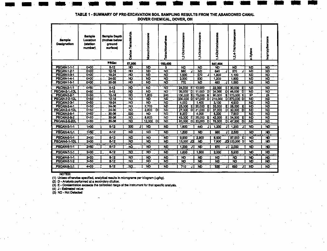
TABLE 1 - SUMMARY OF PRE-EXCAVATION SOIL SAMPLING RESULTS FROM THE ABANDONED CANAL DOVER CHEMICAL. DOVER, OH
Sample Daaisnatlon
Sample LocaUon (ataUon numbei)
Sample Depth (Inches below
greund surtace)
I A
PRGs: 57,900 160,400 547,604 PSCAN-1-1-1 PSCAN-1-2-1
0+00 6-12 MD ND NO ND ND ND ND ND
P8GANTlr3-1 0+00 12r18 ND ND ND 680 J ND 640 370 J ND ND 0+00 10-24 ND ND ND 1,800 570 1,800 1,100 ND ND
PSCAN-1-4-1 O-KIO 24-30 ND ND ND 2,000 830 1,200 1,800 ND ND PSCAN-1-S-1 0+00 30-36 ND ND ND 770 ND 480 1,000 ND ND
PSCAN^2-1-1 ND PSCAh4-2r1-1DL
0+50 6-12 ND ND 24,000 E 13,000 22,000 E 30,000 E ND ND 0+50 6-12 ND ND ND 39J)00 D 11.000 D 34.000 D 46,000 D ND ND
PSCAN-2-2-^1 0+50 12-18 ND 1,800 240 130,000 E 73.000 E 90,000 E 170.000 E 97 25 PSGAN-2-2-1DL 0+50 12-18 ND ND ND 33OjP0O„D 97,000 D 210,000 D 370,000 D ND ND
PSCANr2-a-1 PSC:AN-2-4-I
0+50 18^24 ND ND ND 4,000 1,400 3,100 iiSOO. ND ND 0+-S0 24r30 ND 2,700 ND 25,000 E 20,000 E 33,000 E 2Bfi00 E ND ND
PSCAN-2^1DL 0+50 24-30 ND 2,800 D ND 27,000 D 21,000 D 37^000 D 30,000 D ND ND PSCAN-2T5^1 PSCAN-2-5-2
0+50 30-36 520 ND ND 8,200 4,000 8.200 7:900 ND ND 0+50 30-36 ND 8,600 ND 43,000 E 25,000 E 42,000 E 24,000 E ND ND
PSCAN-2^2DL 0+50 30-36 ND 12,000 D ND 80,000 D 33,000 D 78,000 D 47,000 D ND ND
PSCANr3r1r1 1+00 6-12 300 ND ND 1£00_ 440 JI 1,200 J 1,200 JI ND ND
PSCATMrlrl ND . I ND 1,500 I ND I 980" 2,500 I ND I ND 1+50 6-12 ND
2+00 6-12 ND ND PSCAN-5-1-1DL I 2+00 6-12 ND ND
.PSCAN-6-1-1 I' 2+50"
ND ND ND
6,500 97,000 E ND 7,600 JD 120,000 D ND
ND I 1.200 J I 870 2,000 I ND"
ND ND
6-12 ND ND ND ND
PSGAN.7-1-1 I 3+00' I ND ND I 1,605" 2,000 I 5,900 I N"5" 6^12 ND _iSOO_ ND
PSCAN-S-1-1 I 3+50" ND 6-12 3+50 6-12
ND ND ND ND ND ND
ND ND ND ND
PSCAN-rO-l^l I 4+00~ 6-12 I ND ND ND I 710 JI~ND"
ND ND ND
830 J! 680 J
ND ND
ND ND
I ND ND
NOTES: (1) Unless otherwise spedfled, analytical results In mlcroorams per kilogram (ug/kg), (2) D-Analysis performed at a secondary dilution, (3) E - Conoenbatlon exceeds the calibrated range of the instrument for that specific analysis, (4) J - Estimated value (5) ND-Not Detected
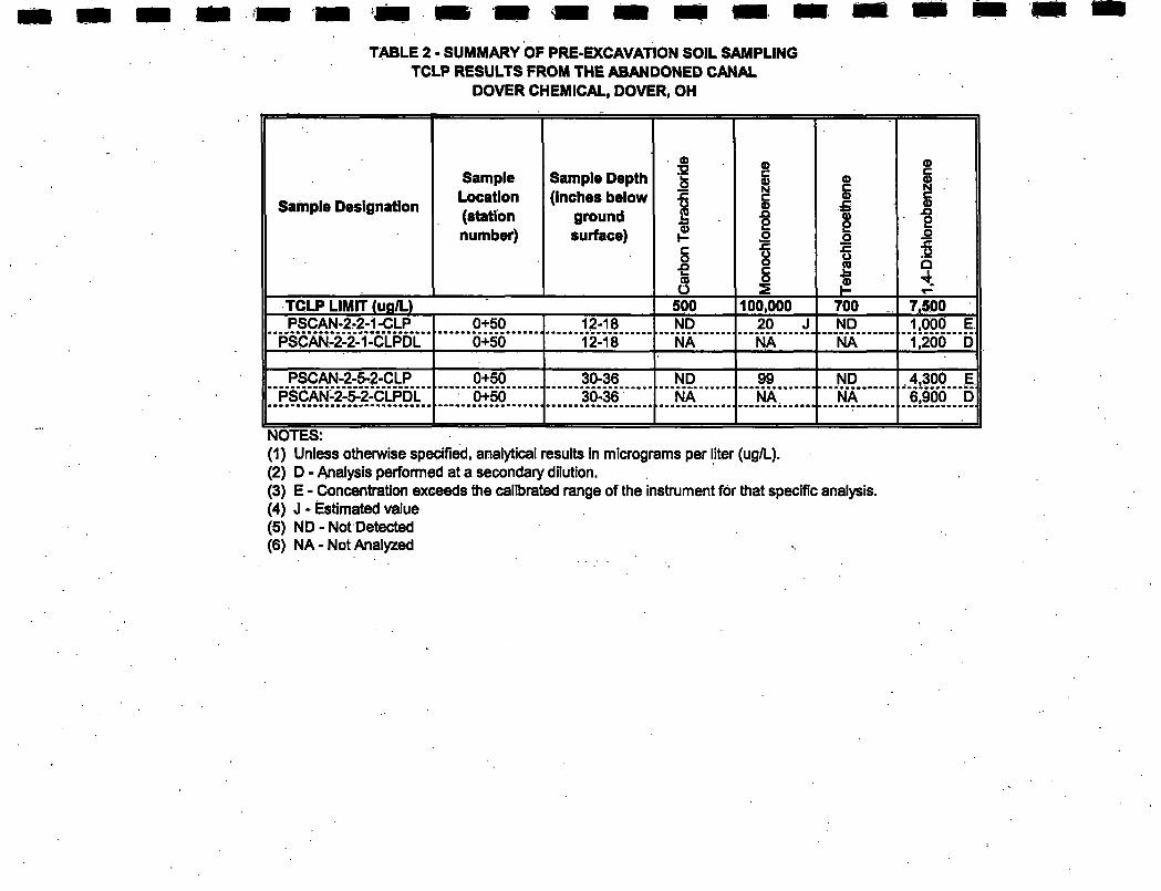
TABLE 2 - SUMMARY OF PRE-EXCAVATION SOIL SAMPLING TCLP RESULTS FROM THE ABANDONED CANAL
DOVER CHEMICAL, DOVER, OH
Sample Designation
Sample Location (station number)
Sampie Depth (inches beiow
ground surface)
Car
bon
Tetra
chlo
ride
s 1 o :§ Q
TCLP LIMIT (ug/L) 500 100,000 700 _ 7,500 PSCAN.2r2-1-CLP 0+50 12-18 ND 20 J ND •'"NA" 1,000 E
"i[20"6""D PSCAN-2-2-1-CLPDL 0+50 12-18 NA NA ND •'"NA" 1,000 E
"i[20"6""D
PSCAN-2-5-2-CLP PSCAN-2-5-2-CLPDL
0+50 ••••••••••••••••••I 0+50
30-36 '36-36"
ND •"NA 99 ""NA
ND •"'NA' .4,300 E "6;9'O'6""D • .
NOTES: (1) Unless otherwise specified, analytical results in micrograms per liter (ug/L). (2) D - Analysis performed at a secondary dilution. (3) E - Concentration exceeds the calibrated range of the instrument for that specific analysis. (4) J - Estimated value (5) ND - Not Detected (6) NA-Not Analyzed
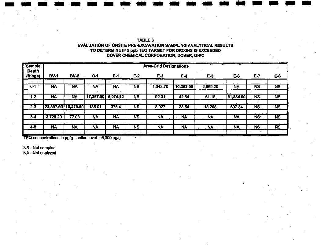
TABLE 3 EVALUATION OF ONSITE PRE-EXCAVATION SAMPLING ANALYTICAL RESULTS
TO DETERMINE IF 5 ppb TEQ TARGET FOR DIOXINS IS EXCEEDED DOVER CHEMICAL CORPORATION, DOVER. OHIO
Sample Depth (ftbgs)
Area-Grid Designations 1
BV-1 BV-2 C-1 E-1 E-2 E-3 E-4 E-5 E-6 E-7 E-8 ||
0-1 NA NA NA NA NS 1,342.70 2,869.20 NA NS NS
.1-2 NA NA 17,367.00 NS 92.01 42.64 61.13. NS NS
2-3 135.01 378.4 NS 8.027 33.54 18.268 697.34 NS NS
3-4 3,720.20 77.03 NA NA NS NA NA NA NA NS NS ••
4-5 NA NA NA NA NS NA NA NA NA NS NS • J
NS - Not sampled NA - Not analyzed
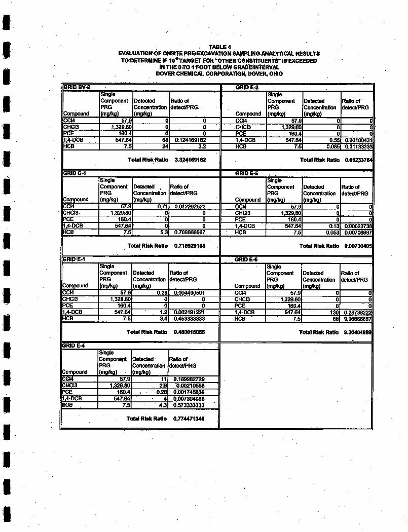
TABLE4 EVALUATION OF ONSITE PRE^CAVATION SAMPLING ANALYTICAL RESULTS TO DETERMINE IF IO'^ TARGET FOR "OtHER:CONSTlTUENTS" IS EXCEEDED
IN THE 0 T01 FOOT BELOW GRADE;INTERVAL DOVER CHEMICAL CORPORATION. DOVER, OHIO
IIGRID BV-2 II: GRID E-3 II
Compound
Single Component PRG
Detected Concentration (mgrtcg)
Ratio of detect/PRG.
Compound
Single Component PRG (mgflco)
Detected Cdncenbation (tng/kg)
Ratlo.of detect/PRG
CCM 57.9 0 1 0 II CCI4 57:9 0 0 CHCI3 1,329.80 0 0 CHCI3 1.329'80 0 0 PCE 160.4 0 0 PCE 160:4 0 0
||l'.4-DCB 547.64 68 0:124169162 1.4-DCB 547.64 0:55 0.00100431 HHee 7.5 24 3.2 HCB 7:5 0:085 0.01133333
Total Risk Ratio 3,324168162 Total Risk Ratio 0.01233764
llGRIDC-1 GRIDE-5 II
Compound
Single Component PRG (mgrtcg)
Detected , Concentration (mg/kg)
Ratloof detect/PKG
Compound
Single Component PRG (fng8«g)
Detected Concentration (nrna)
Ratloof detecl/PRG
ccw 57.9 0.71 0.012262522 GCI4 57.9 0 0 CHCI3 1,329:80 0 0 GHCI3 1,329.80 0 0 PCE 160.4 0 0 PCE 160.4 0 0 1.4-DCB 547.64 0 0 1,4-DCB 547.64 0:13 0:0002373811 HCB 7.5 5.3 0.706666667 HCB 7.5 0.053 mmfmmw
Total Risk Ratio 0.718929166 Total Risk Ratio 0.00730405
||GRIDE-1 GRID E-6
icompound
Single Component PRG (mgflcg)
Detected Concentration (mgykg)
Ratloof detect/PRG
Compound
Single Component PRG (mgfltg)
Detected Concentration (mgfl«g)
Ratloof detect/PRG
CCI4 57.9 o;26 : 0:004490501 CCM 57.9 0 0 CHa3 1,329.80 0 0 CHCI3 1,329.80 0 0 IPCE 160:4 0 0 PCE 160.4 0 0 1.4-DCB 547.64 1.2 0.002191221 1,4-DCB 547.64 130 0.23738222
llHCB 7.5 3.4 0.453333333 HCB 7.5 68 9.06666667
Total Risk Ratio 0:460015055 Total Risk Ratio 9.30404889
GRIDE-4
Compound
Single Component PRG (mgrttg)
Detected Concentration (mgflcg)
Ratloof detect/PRG
CCI4 57.9 11 0.169982729 CHCI3 1,329.80 2:8 0:00210558 PCE 160.4 0.28 0.001745638 i.4.DCB 547.64 4 O.OQ7304068 •
ifilGB 7.5 4.3 0.573333333
• 1 ToUIRIskRaUo 0.774471346
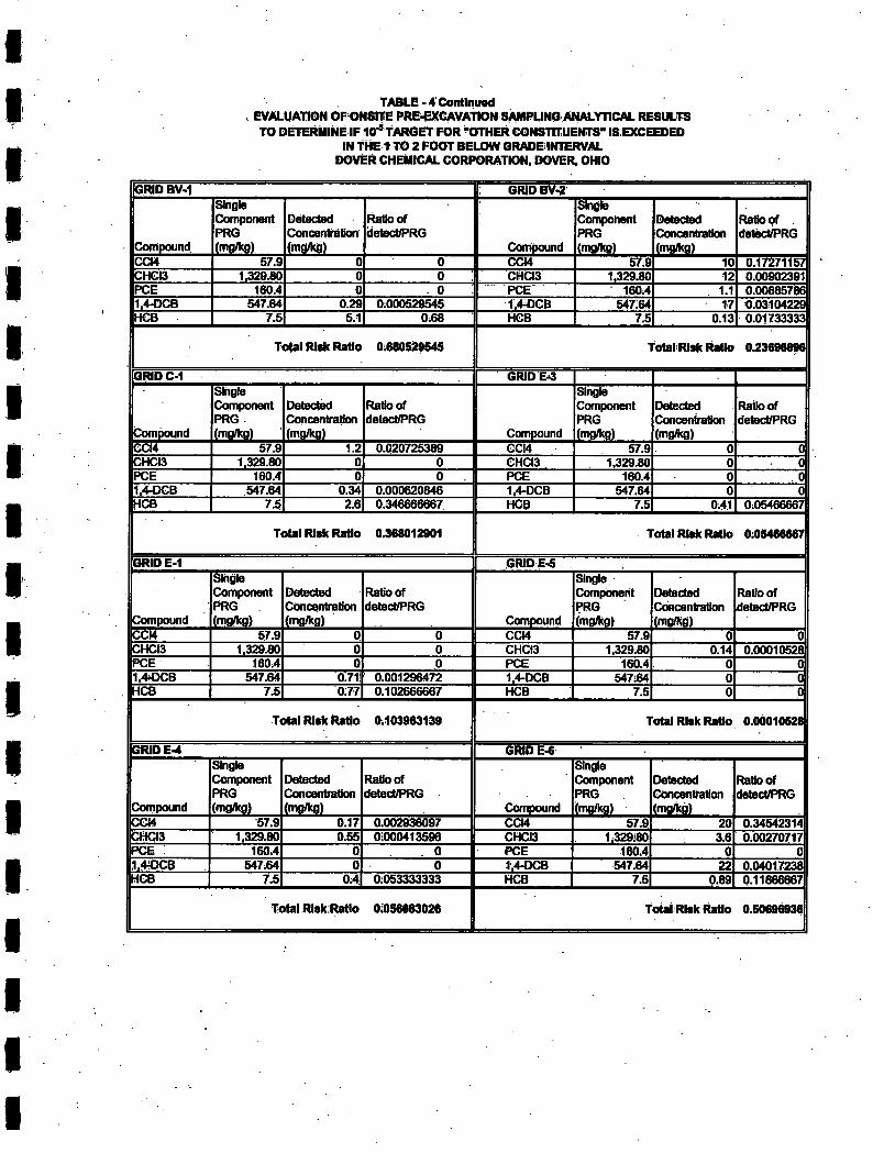
TABLE - 4'Cotitlnua<l EVALUATION OFGNSITE PRE^CAVATION SAMPUNQ ANALYTICAL RESULTS TO DETERMINE IF 10-^ TARGET FOR ^OTHER CONSTITUENTS" IS EXCEEDED
IN THE 1 TO 2 FOOT BELOW GRADE INTERVAL DOVER CHEMICAL CORPORATION, DOVER, OHIO
IIGRID BV-1 B: GRIDBV,2 II
Compound
Single Component RRG (mgAg)
Detected Concentration (mgflcg)
Ratio Of detect/RRG
Compound
Single Component RRG (tngAg)
Detected Concentration (mg/kg)
Ratio of . detect/RRG
COW 57.9 0 0 CCi4 57,9 10 0.17271157 CHGia 1,329.80 0 0 CHCi3 1,329.80 12 0.00902391 ROE 160.4 0 0 RCE 160,4 1.1 0.00685786 1,4-DCB 547.64 0.29 0:000529545 1,44JCB 547:64 17 0.03104229 HCB 7,5 5.1 0,66 HCB 7:5 0.13 0.01733333 •
Total Risk RaUo 0:680529545 Total Risk Ratio 0.23696896
GRIDC-1 GRIDEr3 II
Compound
Single Component RRG (mflfltg)
Detect^
(mflAo)
Ratio of detect/RRG
Compound
Single Component RRG (mgAg)
Detected Concentration j (mgAg)
Ratloof 1 detect/RRG |
CCI4 57.9 1.2 0.020725389 CCI4 57.9 01 0 CHCI3 1,329.80 0 0 eHCi3 1,329.80 0 0 ROE 160.4 0 1 0 . B RCE 160.4 0 . 0
II1.4-DCB 547.64 0.34 0.000620846 1.4-DCB 547.64 0 0 IIHCB 7.5 2.6 0.346666667 HCB 7.5 0:411 0,05466667
Total Risk Ratio 0,368012901 Total Risk Ratio 0:05466667
GRID E-1 GRIDE-5 ||
Compound
Single Component RRG (mgAg)
Detected Concentration (mgAg)
Ratio of detectff>RG
Compound
Single Component RRG (mgflcg)
Detected Concentration (ngfltg)
Ratloof detectd^RG
CCI4 57,9 0 0 CCM 57.9 0 0 CHCI3 1,329.80 0 0 CHCI3 1,329.80 0.14 0.00010528 ROE 160,4 0 0 RCE 160.4 0 0 1,40CB 547.64 0.71i 0.001296472 1,4rDCB 547:64 0 0 HOB 7,5 0;77 0.102666667 HCB 7.5 0 0
Total Risk Ratio 0.103963139 Total Risk Ratio 0.0d010526|
GRID E-4 GRID E,« ||
Compound
Single Component RRG (mgAg)
Detected Ratio of detect/RRG
Compound
Single Component RRG
Detected Ratloof detect/RRG
Compound
Single Component RRG (mgAg) (mgAg)
Ratio of detect/RRG
Compound
Single Component RRG Concentration
(mg/kd)
Ratloof detect/RRG
COM 57.9 0.17 0,002936097 CCM 57,9 20 0.3454231' KCHCI3 1,329.80 0.55 0:000413596 CHCi3 1,329:80 3,6 0,00270717 ROE ; 160,4 0 . 0 RCE 180,4 0 0 1,40CB 547:64 0 0 1,4-OCB 547.64 22 0.04017238
IIHCB 7,5 0:4 0:053333333 HCB 7,5 0,89
Total Rlsk:Ratlo 0:056683026 | T otal Risk Ratio 0,50696936|
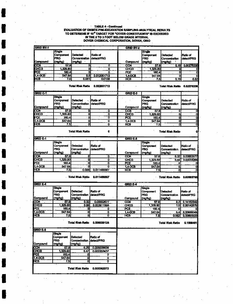
' TABLE 4 • Contlnuad EVALUATION OF ONSITE PRE-EXCAVATlON SAMPUNG ANALYTICAL RESULTS TO DETERMINE IF 10'' tARGET FOR -OTHER CONSTltUENTS" IS EXCEEDED
IN THE 2 TO 3 FOOT BELOW GRADE INTERVAL DOVER CHEMICAL CORPORATION, DOVER, OHIO
GRIDBV-2 GRID BV-1
ikampound
Single CompohOTt PRO £ng(kg2_
Detected Concentration
Ratio of detect/PRG
_Conigoijn^
Single Component PRO
Detect Conosrrtration
Ratio of detectff>RG
CCI4 57.9 004 57.0 0.16 0.00276339 CHCI3 1.329.80 CHOO 1.329.60 PCE 160.4 PCE 160.4
547.64 6.6 0.012051713 1.4rDCB 547.64 7.5 0.061 0:0106 HCB 7.5 0.15 0.02
GRID C-1
Total Risk Raflo 0.022851713 Total Risk RaSo 0.02276339
GRIDE-3
Compound
Single Component PRG ("SM m
Detected Conoentiation (mg/Kg)
Ratio of detect/PRG
Compound
Sidgto Component PRG l!2|£gL
Detected Concentration
Ratioof detect/PRG
CCi4 CCi4 57.9 CHCI3 1.329.60 CHCi3 1.329.60 PCE 160.4 PCE 160.4 .4-DC8 547:64 1.4-DCB 547.64
HCB 7.5 HCB 7.5
GRID E-1
Total Risk Rado Total Risk Rado
GRID E.S
Conipound CCi4 CH03
Single Component PRG inSM.
57.9 1.329:60
Detected Concentration
Ratioof detect/PRG
Compound CCi4 CHCi3
SInSe Oxnponent PRG jmaiisL
57.9 1.329:60
Detected Concentration
iSSM 0.32
Ratioof detect/PRG
0.44 0.00033066 PCE 160.4 PCE 160.4 1.4-DCB HCB
547.64 1.4-DCB 547.64 7.5 0.066 0.011466667 HCB 7.5
GRIDE-4
Total Risk Rado 0.011466667 Total Risk Rado 0.00565765
GRiDE.«
Compound ^14"
Single Component PRG
Detected Concentration imSM
Ratioof detectff>RG
Compound
Single Component PRG
Detected Concentration
Ratioof detectff>RG
57.9 0:00552677 CCi4 57.9 6.2 0.14162349 CHCi3 1.329.60 0.66 0.000511355 CHCi3 1.329.60 1.9 0.00142679 PCE 160.4 PCE 160.4 1.4^DCB HCB
547.64 7.5
1.4-DCB HCB
547:64 7.5
5.4 0.00966049
Total Risk Rado 0.1)06038125 Total Risk Rado 0.1598461
GRIDiE-5
kynpound SCi4 CHa3 PCE .4-DCB
HCB
Component PRG isaSiai.
57.9 1.329.60
160.4 547:64
7:5
Detect Concentration SJSM
0.29 0.47
Ratioof detect/PRG
0.005006636 0.000353437
Total Risk Rado 0.005362072
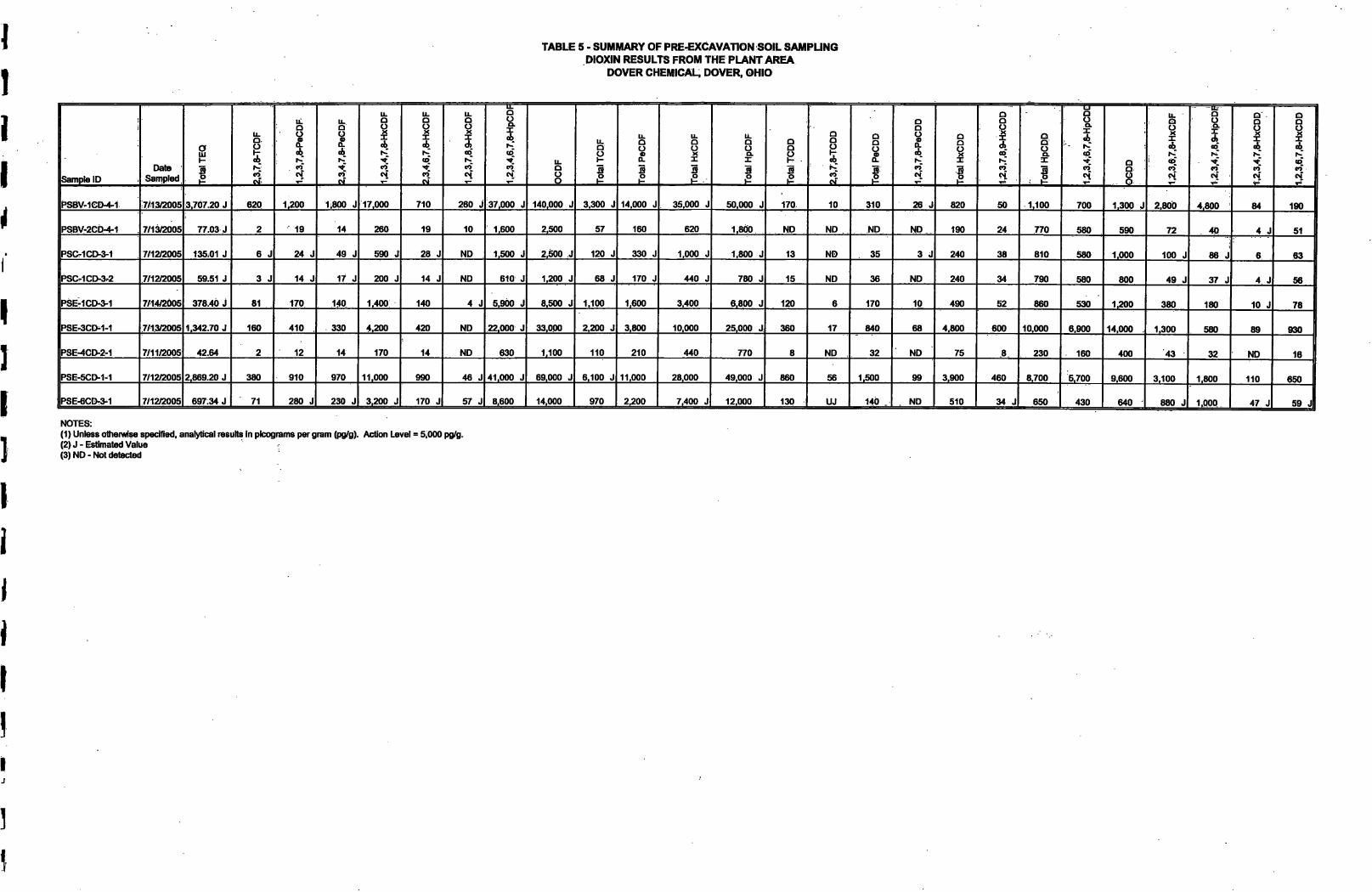
TABLE 5 • SUMMARY OF PRE-EXCAVATION SOIL SAMPLING DIOXIN RESULTS FROM THE PLANT AREA
DOVER CHEMICAL, DOVER, OHIO
Sample ID Date
Sampled Tota
l TE
Q
11. o g K CO
h-"
11. Q
A
S 1,2,
3,4,
7,8-
HxC
DF
2,3,
4.6,
7,8-
HxC
DF u.
1 ? CO
1,2,
3,4,
6,7,
8-H
pCD
F
OC
DF
Tota
l TC
DF
Tota
l PeC
DF
|j
Tota
l HxC
DF • To
tal H
pCD
F
Tota
l TC
DD
Q
1 CO
Tota
l PeC
DD
1,2,
3,7,
8-P
eCD
D
Tota
l HxC
DD
O Q
«>:
B Tota
l HpC
DD
O
, I tC CO*
CO Q
1,2,
3,6,
7,8-
HxC
DF a
1 «?. CM. V-
Q
CO
i- 1.,2
,3,6
,7,8
-HxC
DD
PSBV-ietMri 7/1312005 3.707.20 J 620 1,200 1:800 J 17,000 710 260 J :37,000 J 140,000 J 3,300 J 14,000 J 35,000 J 50,000 J 170. 10 310 26 J 820 50 1,100 700 1.300 J 2,800 4,800 : 84 190
PSBV-2eb-4-1 7/13/2005 77.03 J 2 19 14 260 19 10 1,600 2,500 57 160 620 1,800 ND ND ND ND.. 190 24 770 580 590 72 40 4 J 51
PSCTICD-S-I 7/12G005 135,01 J 6 J 24 J 49 J 590 J 28 J ND 1,500 J 2,»0 J 120 J 330 J 1,000 J 1,800 J 13 ND 35 3 J 240 38 810 580 1,000 100 J 88 J 6 63
PSC-1CD-3-2 7/12^005 59.51 J 3 J 14 J 17 J 200 J 14 J ND 610 J 1,200 J 68 J 170 J 440 J 780 J 15 ND 36 ND 240 34 790 580 800 49 J 37 J 4 J 56
PSE-1CD-3-1 7/14/2005 378.40 J 81 170 140 1,400 140 4 J 5,900 J 8,500 J 1,100 1,600 3,400 6,800 J 120 6 170 10 490 52 860 530 1,200 380 180 10 J 78
PSE.3CD^1-1 7/13Q005 1,342.70 J 160 410 330 4,200 420 ND 22,000 J 33,000 2,200 J 3,800 10,000 25,000 J 360 17 840 68 4,800 600 10.000 6,900 14,000 1,300 580 89 930
PSE-4CD-2-1 7/11/2005 42.64 2 12 14 170 14 ND 630 1,100 110 210 440 770 8 ND 32 ND 75 8 230 160 400 43 32 ND 16
PSE-5CD-M 7/12C005 2,869.20 J 380 910 970 11.000 990 46 J 41,000 J 69.000 J 6,100 J 11,000 28,000 49.000 J 860 56 1,500 99 3,900 460 8,700 5.700 9,600 3,100 1,800 110 650
PSE-6CDr3^1 7/12«005 697:34 J 71 280 J 230 J 3,200 J 170 J 57 J 8,600 14,000 970 2,200 7,400 J 12,000 130 UJ 140 . ND 510 34 J 650 430 640 880 J 1,000 47 J 59 J
NOTES: (1) Unless othenwise specified, analytical results In picograms per gram (pg/g). Action Level = 5,000 pg/g. (2) J-Estimated Value (3) ND-Not detected
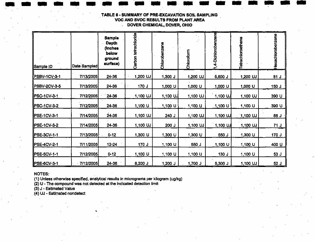
TABLE 6 - SUMMARY OF PRE-EXCAVATION SOIL SAMPLING VOC AND SVOC RESULTS FROM PLANT AREA
. DOVER CHEMICAL. DOVER. OHIO
Sample ID Date Sampled
Sample Depth
(Inches below
ground surface)
Car
bon
tetra
chlo
ride
Chi
orob
enze
ne
Chl
orof
orm
1,4-
Dic
hior
oben
zene
Tetir
achi
oroe
then
e
1 I
PSBV-1CV-3-1 7/13/2005 24-36 1,200 UJ 1,300 J 1,200 UJ 5,800 J 1,200 UJ 81 J
PSBV-2CV-3-5 7/13/2005 24-36 170 J 1,000 U 1,000 U 1,000 U 1,000 U . mj._
PSC^1CV-3-1 7/12/2005 24-36 1,100 UJ 1,100 UJ 1,100 UJ 1,100 UJ 1,100 UJ 390 U
PSC-1CV-3-2 7/12/2005 24-36 1,100 U 1,100 U 1,100 U 1,100 U 1,100 U 390 U
PSE-1CV-3-1 7/14/2005 24-36 1,100 UJ 240 J 1,100 UJ 1,100 UJ . 1,100 UJ 86 J
PSE-1CV-3-2 7/14/2005 24-36 1,100 UJ 200 J 1,100 UJ 1,100 UJ 1,100 UJ 71 J
PSE-3CV-1-1 7/13/2005 0-12 1,300 U 1,300 U 1,300 U 550 J 1,300 U 170 J
PSE-4CV-2-1 7/11/2005 12-24 170 J 1,100 U 550 J 1,100 U 1,100 U _400 U,
PSE-5CV-1-1 7/12/2005 0-12 1,100 U 1,100 U 1,100 U 130 J 1,100 U 53 J
PSE-6CV-3-1 7/12/2005 24-36 8,200 J 1,200 J . 1,700 J 5,300 J 1,100 UJ 52 J
NOTES: (1) Unless otherwise specified, anaiyticei results in micrograms per kilogram (ug/kg) (2) U - The compound was not detected at the indicated detection limit (3) J-Estimated Value (4) UJ - Estimated nondetect
: -/ I
Figures
1 J
U006-270
CONCRETE STRUCTURE
NOTES:
1. BASE MAP PREPARED BY: WARD & ELMER SURVEYING. INC. 113 THIRD STREO, S.E. NEW PHILADELPHiA, OHIO 44663
2. CONTOUR INTERVAL: 1 FOOT
3. VERTICAL DATUM: USGS TABLCT 0-121 ELEVATION 885.09' (1929 DATUM)
4. PRE-EXCAVATION SOIL SAMPLE LOCATIONS ARE APPROXIMATE AND WERE LOCATED BY FIELD MEASUREMENTS.
LEGEND:
PRE-EXCAVATION SOIL SAMPLE LOCATION
PRE-EXCAVATION SAMPLE DESIGNATION
AREA TO BE EXCAVATED TO A DEPTH OF 1 FOOT BELOW GRADE
AREA TO BE EXCAVATED TO A DEPTH OF 3 FEET BELOW GRADE
Ground Eiev. « 875.7' Top Elev. = 878.18' Inside Elev. = 877.59'
APPROXIMATE LOCATION OF HAY BALE/SILT FENCE
APPROXIMATE GRAPHIC SCALE
20" 80"
ABANDONED CANAL EXISTING CONDITIONS AND
LIMIT OF EXCAVATION DOVER CHEMICAL CORPORATION
DOVER, OHIO
TRC Mt HH« U>^
DRAWN BY: HWB DATE: CHECKED BY: ACH 5/31/06
FIGURE 1
int.
••'- -- •.VT T ---• . • •• J,"—r -• •••.
i vV iv .:;• GAT£
DAVIS S-^EET
• V , -r
JOrnKGr m
• : •
n I '•• ^ ' " ̂ '/=•'] fcr— r —- -.^ ; • ; • • i •; -iol'! r;/.'
TSt^
-t^LS- : ^ :'t* "r::i : •-• !| ̂
- . .. ••>! r-.A 4
S''':-i_^pk^.^ia^
w r<- 32
C" ''•••' f d ' '
D' ^c;'
iu! —i' ...'
TW4^:'>. -sTRarTyfte? ovCR T)LS
<:»R CMtP -f
COUCRHTgOR^-.PHJvT I ': -i RS-'JEOl-TEC
;. Soi:Sar-ii{.'»g;.ec3i;&n
* • * < 5C-raet Comp3S;:»? 3fU .77 NORTH -It::;?
C=vT=-;rn.t
J:\Projects\41768 - Dover\Figure 2 • PLANTEXC.PPT
. PROPOSED EXTENT OF EXCAVATION
100
PLANT AREA PROPOSED EXCAVATION AREAS MAP
DOVER CHEMICAL CORP. Boott Mills South 116 John Street Lowell, Massachusetts 01852 978-970>5600
Drawn: HWB
Checked: AH
SCALE: AS SHOWN Date 12/15/05
FIGURE 2
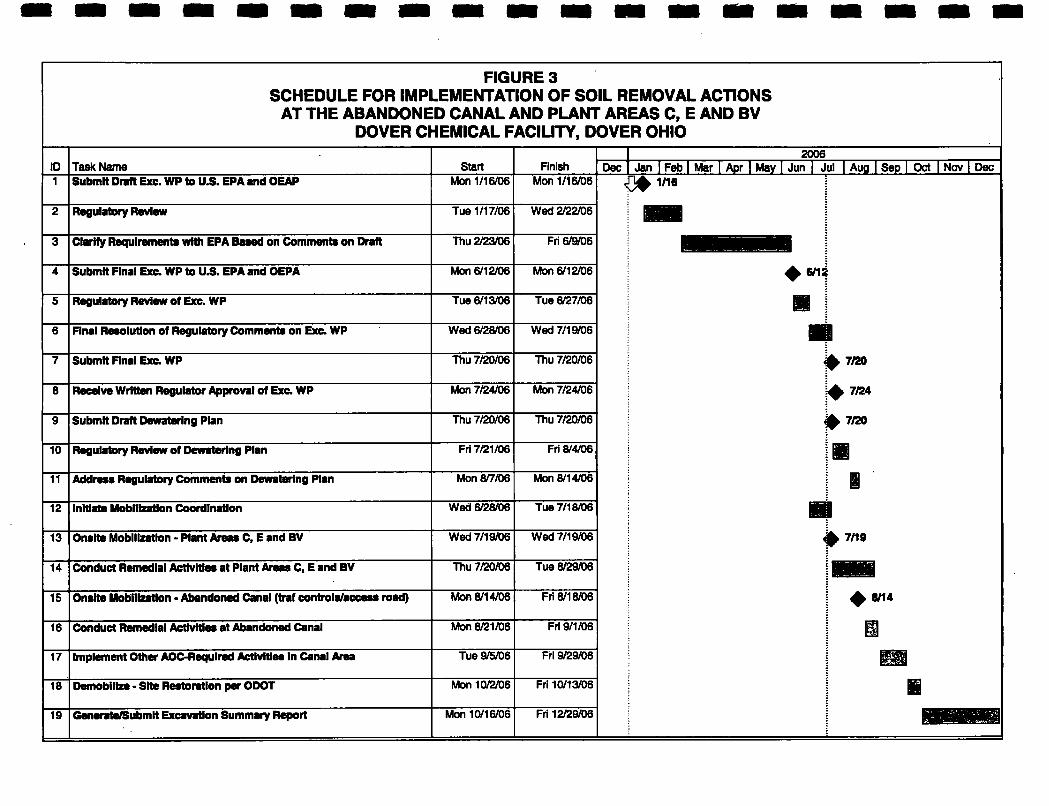
FIGURE 3 SCHEDULE FOR IMPLEMENTATION OF SOIL REMOVAL ACTIONS
AT THE ABANDONED CANAL AND PLANT AREAS C, E AND BV DOVER CHEMICAL FACILITY, DOVER OHIO
1 2006 ID Task Name Start Finish Dec 1 Jan I Feb I Mar I Apr I May I Jun | Jul I Aug I Sep I Oct I Nov | Dec 1 Submit Draft Exe. WP to U.S. EPA and GEAP Men 1/16/D6 Mon 1/16/06 1/16
2 Regulatory Review Tue 1/17/06 Wed 2/22/06 1 •• 3 Clarify Requirements with EPA Based on Comments on Draft Thu 2/23/06 Fri 6/9/06
4 Submit Final Exe. WP to U.S. EPA and OEPA Mon 6/12/06 Mon 6/12A36 >
5 Regulatory Review of Exe. WP Tue 6/13/06 Tue 6/27/06 11 6 Final Resolution of Regulatory Comments on Exc. WP Wed 6/28A)6 Wed7/19«)6 • 7 Submit nnal Exc. WP Thu 7/20/06 Thu 7/20/06 ^ 7/20
8 Mon 7/24/06 Mon 7/24/06 ^ 7/24
9 Submit Draft Dewataring Plan Thu 7/20/06 Thu 7/20/06 7/20
10 Regulatory Review of Dewatering Plan FrI 7/21/06 Frl8/4A)6, m 11 Address Regulatory Comments on Dewatering Plan Mon 8/7/06 Mon 8/14/06 i 12 Initiate Mobilization Coordination Wed 6/28/06 Tue 7/18/06 • i 13 Onslts Mobilization - Plant Areas C, E and BV Wed 7/19/06 Wed 7/19/06 pinB
14 Conduct Remedial Activities at Plant Areas C, E and BV Thu 7/20/06 Tue 8/29/06 :
15 Onslte Mobilization - Abandoned Canal (traf conbola/access road) Mon 8/14/06 Fri 8/18/06 ^ 8/14
16 Conduct Remedial Activities at Abandoned Canal Mon 8/21/06 FrI 9/1/06 1 17 Implement Other AOC-Requlred Activities in Canal Area Tue 9/5A)6 Fri 9/29/06 n 18 Demobilize - Site Restoration per ODOT Mon 10/2/06 Fri 10/13/06 1 19 Generate/Submit Excavation Summary Report Mon 10/16/06 Fri 12/29/06 iHBBmiiwriiil
Attachment A
EPA Letter Dated October, 2005 Regarding Modification of the AOC dated October 20,2000 -Lagoon Area and Canal Soils/Sediment and Plant
Area Soil
See draft January 2006.
L2006-270
Attachment B
Pre-excavation Analytical Sampling Results
See draft January 2006.
U006-270
Attachment C
Data Validation Reports
See draft January 2006.
L2006-270
Attachment D
Amendment to the Health and Safety Plan (HASP)
See draft January 2006.
L2006-270
wimmmmmmmmsmm
Attachment E
Ohio DOT Permit
See draft January 2006.
U006-270
Attachment F
Amendment to the Quality Assurance Plan (QAPP)
See draft January 2006.
L2006-270
Attachment G
October 4,2005 Email Message from EPA Regarding Pre-Excavation Sampling at Onsite
Areas C, E and BV
L2006-270
Plumbj Mike
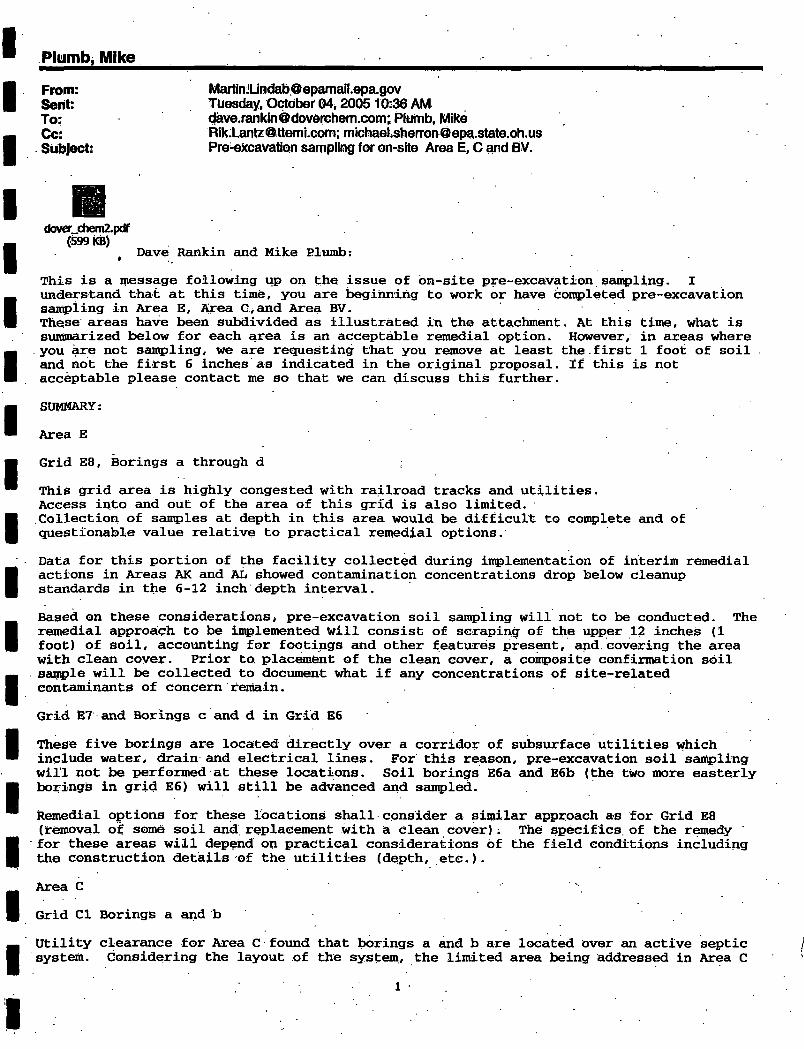
From: [email protected] Sent: Tuesday, October 04,200510:36 AM To; dave,[email protected];.PIurab, Mike Cc: Rik:[email protected]; raichael.sberron@epa^state,oh:us Subject: Pre^excavation sampling for on-site Area E, C and BV.
clover_chem2.pdf (SOTiCB)
Dave Rankin and Mike Slumb:
This is a message following up on the issue of on-site pre-excavation seui^ling. I understand that at this time, you are beginning to work or have conpleted pre-excavation san^iing in Area E, Area Gvand Area BV. These areas have been subdivided as illustrated in the attachment. At this time, what is suinmarized below for each area is an acceptable remedial option. However, in areas where you are not sair^jling, we are requesting that you remove at least the.first 1 foot of soil and not the first 6 inches as indicated in the original proposal. If this is not acceptable please contact me so that we can discuss this further.
SUMMARY:
Area E
Grid E8, Borings a through d
This grid area is highly congested with railroad tracks and utilities. Access into and out of the area of this grid is also limited. .Collection of samples at depth in this area would be difficult to con^lete and of questionable value relative to practical remedial options.
Data for this portion of the facility collected during implementation of interim remedial actions in Areas AK and AL showed contamination concentrations drop below cleanup standards in the 6-12 inch depth interval.
Based on these considerations, pre-excavation soil sampling will not to be conducted. The remedial approach to be in^lemented will consist of scraping of the upper 12 inches (1 foot) of soil, accounting for footings and other features present, and. covering the area with cleeui coyer. Prior to. placement of the clean cover, a composite confirmation soil Scmiple will be collected to document what if any concentrations Of site-related contaminants of concern remain.
Grid E7 cind Borings c and d in Grid E6
These five borings are located directly over a corridor of subsurface utilities which include water, drain and electrical lines. For this reason, pre-excavation soil sampling will not be performed at these locations. Soil borings E6a auid E6b (the two more easterly borings in grid E6) will still be advanced cuid sctmpled.
Remedial options for these locations shall consider a similar approach as for Grid E8 (removal of some soil and replacement with a clean cover) i The specifics, of the remedy for these areas will depend on practical considerations of the field conditions including the construction details of the utilities (depth, etc.).
Area C
Grid CI Borings a and b
Utility clearance for Area C found that borings a and b are located over an active septic system. Considering the layout of the system, the limited area being addressed in Area C
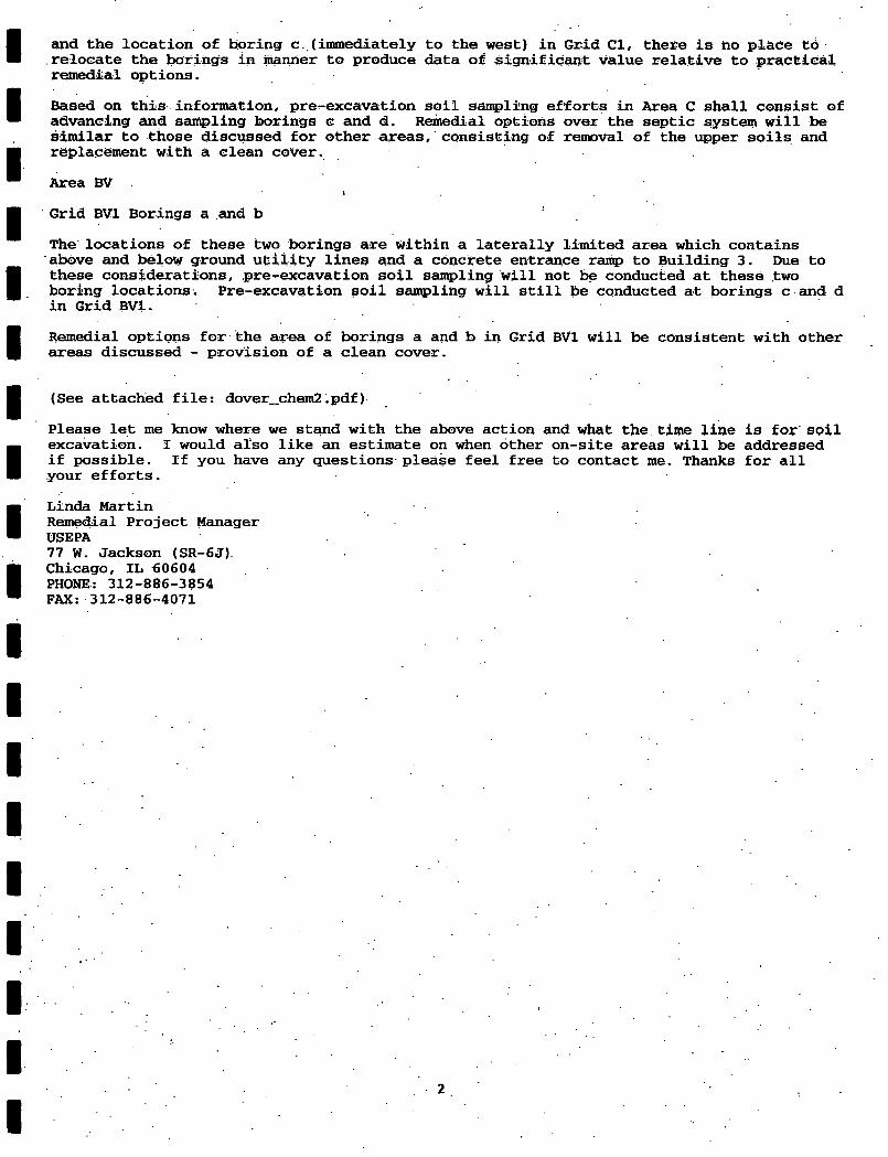
and the location of boring c .(immediately to the west) in Grid Gl, there is no place td relocate the borings in manner to produce data of significaht value relative to practical remedial options.
Based on thiis information, pre^excavation soil saii^llng efforts in Area C shall consist of advancing eind san^ling borings c and d. Remedial options over the septic system will be similar to those discussed for other areas, consisting of removal of the upper soils and replacement with a clean cover.
Area BV t
Grid BVl Borings a .and b
The locations of these two borings are within a laterally limited area which contains above and below ground utility lines and a concrete entrance ramp to Building 3. Due to these considerations, pre-excavation soil sampling will not be conducted at these two boring locations. Pre-excavation soil seimpling will still be conducted at borings c and d in Grid BVl.
Remedial options for the area of borings a and b in Grid BVl will be consistent with other areas discussed - provision of a clean cover.
(See attached file; dover_chem2.pdf)
Please let me know where we stand with the above action and what the time line is for soil excavation. I would also like an estimate on when other on-site areas will be addressed if possible. If you have any questions please feel free to contact me. Thanks for all your efforts.
Linda Martin Remedial Project Manager USEPA 77 W. Jackson (SR-6J) Chicago, XL 60604 PHONE: 312-886-3854 FAX: 312-886-4071
2