Embed Size (px)
Citation preview

Accuracy Is TheUnderlying Strategy
GCTS is committed to designing accurate testing systems by integrating innovative software engineering with advanced hardware.
Advanced Testing Systems
MADE IN USA

GCTS is internationally renowned for its high quality testing systems and client care. The design approach GCTS has utilized emphasizes the importance of the customer’s needs. It is this approach that has dictated the level of success we have achieved to this date. GCTS does not just offer testing equipment; we provide complete solutions for advanced material characterization. All of our systems are proudly designed and manufactured in the United States of America. Our systems are designed to maximize client productivity by acquiring and processing testing data, then presenting the results in a simple and coherent format.
Company Vision
GCTS: Global Presence

Product Overview
Rock Testing Systems ............................................................................................. 4 Digital Point Load Testing System (PLT-100) ........................................................................................... 4 Digital Point Load Testing System (PLT-110) ........................................................................................... 5 Digital Rock Direct Shear System (RDS-100) ........................................................................................... 6 Servo-Controlled Rock Direct Shear System (RDS-200) .......................................................................... 7 Servo-Controlled Rock Direct Shear System (RDS-300) .......................................................................... 8 Triaxial / Direct Shear Rock Testing System (RDS-500) ........................................................................... 9 Uniaxial Testing System (UCT-1000) ..................................................................................................... 10 Rapid Triaxial Rock Testing System (RTR-1000) .................................................................................... 11 Rapid Triaxial Rock Testing System (RTR-1500) ..................................................................................... 12 Triaxial Rock Testing System (RTX-1000) ............................................................................................... 13 Triaxial Rock Testing System (RTX-1500) ............................................................................................... 14 Triaxial Rock Testing System (RTX-3000) ............................................................................................... 15 Rock Creep Testing System (RCT-2000) ................................................................................................ 16
Rock Testing Components ................................................................................... 17 Pressure Intensifier System (HPVC) ....................................................................................................... 17 High Pressure Triaxial Cells (HTRX) ........................................................................................................ 18 Rock Deformation Device (DEF-5000) ................................................................................................... 22 Differential Strain Analysis (DSA-12)...................................................................................................... 23 Fast Pulse Decay Permeability Apparatus (HPPD-20) ............................................................................ 24 Rock Abrasiveness Apparatus (RAA-100) ............................................................................................... 25 Ultrasonic Velocity Apparatus (ULT-100) ............................................................................................... 26 Circumferential Velocity Apparatus (CVA-100) ..................................................................................... 27 Rock Polyaxial Fixture (RPX-150) ........................................................................................................... 28 Hydraulic Fracture Test Fixture (HTRX-HF) ............................................................................................ 29 Digital Signal Conditioning and Control Unit (SCON-1500/2000) .......................................................... 30 Computer Aided Testing Software (CATS-ADV) ..................................................................................... 31 Rock Triaxial Software Module (CATS-TRX-ROCK) ................................................................................. 32 Direct Shear Testing Module (CATS-DSH) .............................................................................................. 33 Point Load Test Software (PntLoad) ...................................................................................................... 34 Heavy Duty Laboratory Coring Machine (RCD-200) .............................................................................. 35 Pressure Controlled Coring Machine (RCD-250) .................................................................................... 35 Specimen Grinder (RSG-200) ................................................................................................................. 36 Specimen Lab Saw (RLS-100) ................................................................................................................. 36 Rock Testing Accessories ....................................................................................................................... 37

4 www.gcts.com
• 100 kN (22 kips) load capacity, larger capacities
available
• Compact, light design (< 15 kg)
• Output display in SI or English units
• Digital output with 10 N (or 1 lb) resolution
• Dual signal outputs to a computer or data recorder
• Software for fast and automatic testing
• Increases test production and minimizes
operational errors
• 110/220 VAC or 12 VDC operation
• Optional ultrasonic velocity point load platens
• Platens and frames are available to perform
Uniaxial, Brazilian, Hardness, and Ultrasonic tests
Specifications
PLT-100
Load Capacity 100 kN Shipping Volume 0.11 m3 Shipping Mass 27 kg Stroke 54 mm Vertical Opening 125 mm Horizontal Opening 100 mm
Digital Point Load Testing System
Accessories 1. Watertight, airtight, crushproof carrying case. 2. Automatic size gauging & deformation transducer. 3. Automatic data acquisition system. 4. Unconfined compression load platens. 5. Ultrasonic velocity measurement system.
For more accessories please contact GCTS.
Description
The GCTS Point Load Tester is an apparatus made of high strength anodized aluminum that incorporates digital technology to increase precision and ease of use while reducing its size and mass. The introduction of a pressure sensor to measure load provides a better accuracy at any load level eliminating the imprecision of the traditional pressure gauges at low load ranges. The system has a digital load display, as well as an analog pressure gage, that continuously monitors the applied load. The maximum load is automatically stored and easily obtainable by pressing a button. An advanced option for this system are the ultrasonic platens for the measurement of P-wave (compressional wave) velocity. The P-wave velocity is a more rational method and gives a better correlation to strength than the point load index. The major advantage of the ultrasonic velocity option is that, as with the point load test, it does not require expensive specimen preparation. The P-wave velocity is measured during the point load test. Other options include: platens, triaxial cells, and frames for performing uniaxial and triaxial tests on small specimens. These options include software that captures the complete stress-strain curve and automatically calculates the parameters.
Indirect tension Brazilian test jig. Weatherproof carrying case.

5
• 100 kN (22 kips) load capacity, larger capacities
available
• Compact, light design (< 14 kg)
• Output display in SI units
• Digital output with 10 N (or 1 lb) resolution
• Dual signal outputs to a computer or data recorder
• Software for fast and automatic testing
• Increases test production and minimizes
operational errors
• Internal battery operation
• Optional ultrasonic velocity point load platens
• Platens and cells are available to perform Triaxial,
Uniaxial, Brazilian tests
Specifications
PLT-110
Load Capacity 100 kN Shipping Volume 0.13 m3 Shipping Mass 26 kg Stroke 54 mm Vertical Opening 125 mm Horizontal Opening 100 mm
Digital Point Load Testing System
Accessories 1. Watertight, airtight, crushproof carrying case. 2. Automatic size gauging & deformation transducer. 3. Automatic data acquisition system. 4. Unconfined compression load platens. 5. Ultrasonic velocity measurement system.
For more accessories please contact GCTS.
Description
The GCTS Point Load Tester is an apparatus made of high strength anodized aluminum that incorporates digital technology to increase precision and ease of use while reducing its size and mass. The introduction of a pressure sensor to measure load provides a better accuracy at any load level eliminating the imprecision of the traditional pressure gauges at low load ranges. The system has a digital display that continuously monitors the applied load. An optional second display provides specimen size in millimeters (or inches). The maximum load is automatically stored and easily obtainable by pressing a button. An advanced option for this system are the ultrasonic platens for the measurement of P-wave (compressional wave) velocity. The P-wave velocity is a more rational method and gives a better correlation to strength than the point load index. The major advantage of the ultrasonic velocity option is that, as with the point load test, it does not require expensive specimen preparation. The P-wave velocity is measured during the point load test. Other options include: platens, triaxial cells, and frames for performing uniaxial and triaxial tests on small specimens. These options include software that captures the complete stress-strain curve and automatically calculates the parameters.
PLT software.
6 www.gcts.com
Digital Rock Direct Shear System
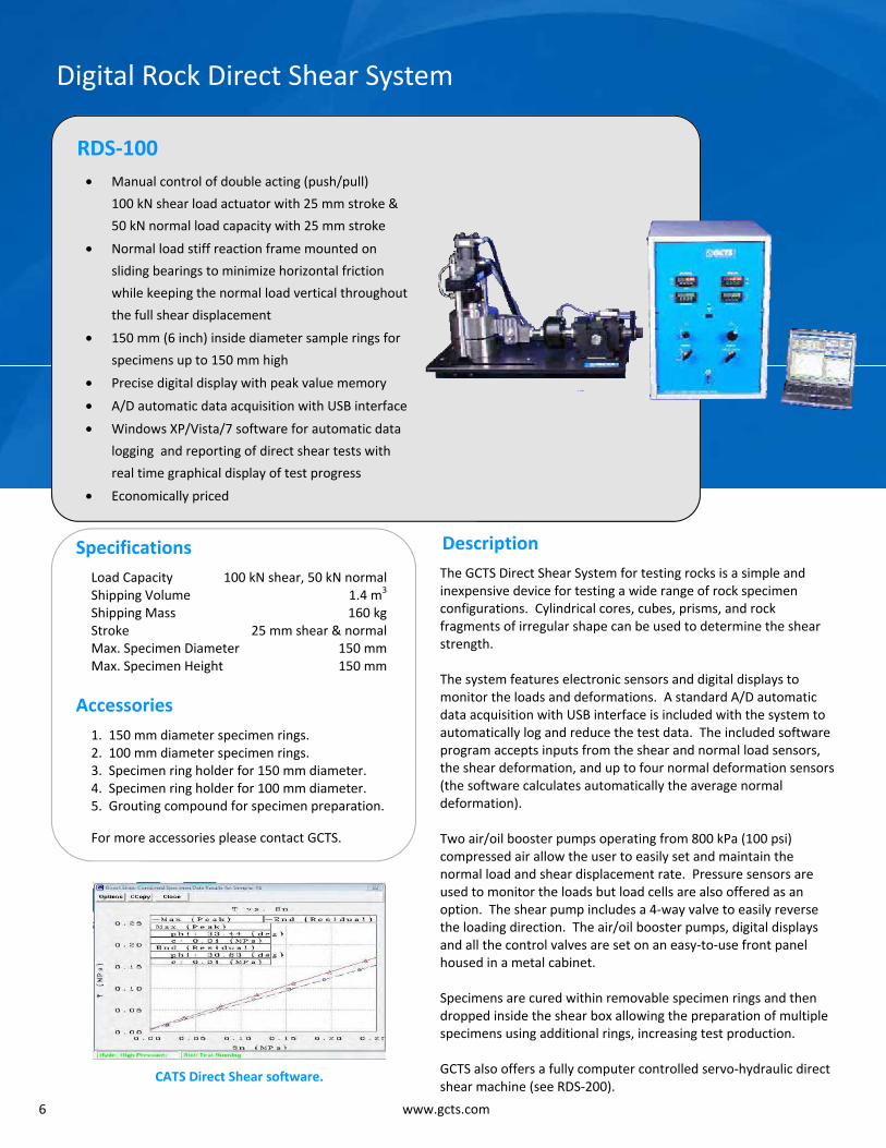
RDS-100 • Manual control of double acting (push/pull)
100 kN shear load actuator with 25 mm stroke &
50 kN normal load capacity with 25 mm stroke
• Normal load stiff reaction frame mounted on
sliding bearings to minimize horizontal friction
while keeping the normal load vertical throughout
the full shear displacement
• 150 mm (6 inch) inside diameter sample rings for
specimens up to 150 mm high
• Precise digital display with peak value memory
• A/D automatic data acquisition with USB interface
• Windows XP/Vista/7 software for automatic data
logging and reporting of direct shear tests with
real time graphical display of test progress
• Economically priced
Specifications Load Capacity 100 kN shear, 50 kN normal Shipping Volume 1.4 m3 Shipping Mass 160 kg Stroke 25 mm shear & normal Max. Specimen Diameter 150 mm Max. Specimen Height 150 mm
Accessories 1. 150 mm diameter specimen rings. 2. 100 mm diameter specimen rings. 3. Specimen ring holder for 150 mm diameter. 4. Specimen ring holder for 100 mm diameter. 5. Grouting compound for specimen preparation.
For more accessories please contact GCTS.
Description The GCTS Direct Shear System for testing rocks is a simple and inexpensive device for testing a wide range of rock specimen configurations. Cylindrical cores, cubes, prisms, and rock fragments of irregular shape can be used to determine the shear strength. The system features electronic sensors and digital displays to monitor the loads and deformations. A standard A/D automatic data acquisition with USB interface is included with the system to automatically log and reduce the test data. The included software program accepts inputs from the shear and normal load sensors, the shear deformation, and up to four normal deformation sensors (the software calculates automatically the average normal deformation). Two air/oil booster pumps operating from 800 kPa (100 psi) compressed air allow the user to easily set and maintain the normal load and shear displacement rate. Pressure sensors are used to monitor the loads but load cells are also offered as an option. The shear pump includes a 4-way valve to easily reverse the loading direction. The air/oil booster pumps, digital displays and all the control valves are set on an easy-to-use front panel housed in a metal cabinet. Specimens are cured within removable specimen rings and then dropped inside the shear box allowing the preparation of multiple specimens using additional rings, increasing test production. GCTS also offers a fully computer controlled servo-hydraulic direct shear machine (see RDS-200).
CATS Direct Shear software.
7
Servo Controlled Rock Direct Shear System
RDS-200 • Closed loop servo control of double acting (push/
pull) 100 kN shear load actuator with 25 mm stroke
and 50 kN normal load capacity with 25 mm stroke
• Normal load stiff reaction frame mounted on sliding
bearings to minimize horizontal friction while
keeping the normal load vertical throughout the full
shear displacement
• 150 mm (6 inch) inside diameter sample rings for
specimens up to 150 mm high
• Software for automatic performance of direct shear
tests with constant normal stress or normal stiffness
• Real time graphical display of test progress
• Other load capacities and specimen sizes are
available, including large-scale test systems for shear
loads of up to 1,000 kN and specimen sizes up to
300 mm diameter or side
Specifications Load Capacity 100 kN shear, 50 kN normal Shipping Volume 2.1 m3 Shipping Mass 360 kg Stroke 25 mm shear & normal Max. Specimen Diameter 150 mm Max. Specimen Height 150 mm
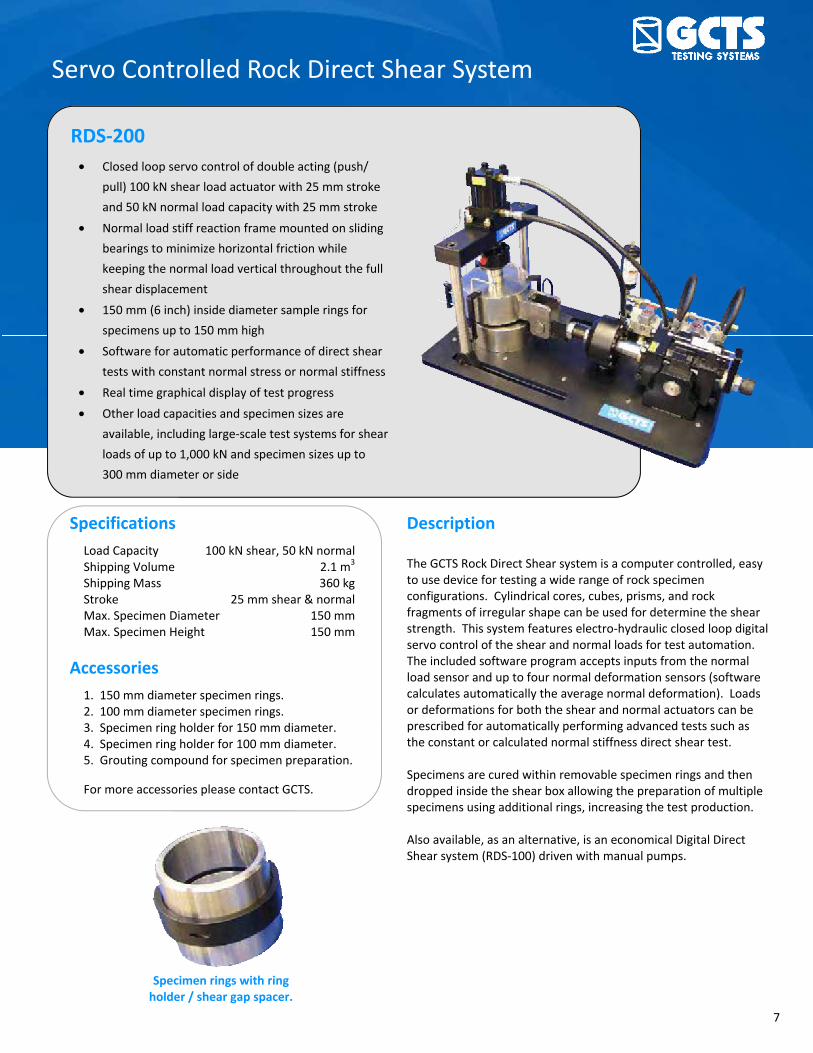
Accessories 1. 150 mm diameter specimen rings. 2. 100 mm diameter specimen rings. 3. Specimen ring holder for 150 mm diameter. 4. Specimen ring holder for 100 mm diameter. 5. Grouting compound for specimen preparation.
For more accessories please contact GCTS.
Description
The GCTS Rock Direct Shear system is a computer controlled, easy to use device for testing a wide range of rock specimen configurations. Cylindrical cores, cubes, prisms, and rock fragments of irregular shape can be used for determine the shear strength. This system features electro-hydraulic closed loop digital servo control of the shear and normal loads for test automation. The included software program accepts inputs from the normal load sensor and up to four normal deformation sensors (software calculates automatically the average normal deformation). Loads or deformations for both the shear and normal actuators can be prescribed for automatically performing advanced tests such as the constant or calculated normal stiffness direct shear test. Specimens are cured within removable specimen rings and then dropped inside the shear box allowing the preparation of multiple specimens using additional rings, increasing the test production. Also available, as an alternative, is an economical Digital Direct Shear system (RDS-100) driven with manual pumps.
Specimen rings with ring holder / shear gap spacer.

8 www.gcts.com
Servo Controlled Rock Direct Shear System
RDS-300 • Closed loop servo control of double acting (push/
pull) 300 kN shear load actuator with ± 50 mm
stroke and 300 kN normal load capacity with
100 mm stroke
• Includes adjustable locking mechanism to prevent
rotation of the top box in any one direction, two
directions, or none (fixed so that no shear plane
rotations are allowed)
• Accepts 150 mm (6 inch) diameter samples as well
as 100 mm x 100 mm cubical specimens up to
150 mm high
• Software for automatic performance of direct shear
tests with constant normal stress or normal stiffness
• Other load capacities and specimen sizes are
available, including large-scale test systems for shear
loads of up to 1,000 kN and specimen sizes up to
300 mm diameter or side
Specifications Load Capacity 300 kN shear, 300 kN normal Shipping Volume 2.7 m3 Shipping Mass 1,100 kg Stroke ± 50mm shear, 100 mm normal Max. Specimen Diameter 150 mm Max. Specimen Height 150 mm
Accessories 1. 150 mm diameter specimen rings. 2. 100 mm diameter specimen rings. 3. Specimen ring holder for 150 mm diameter. 4. Specimen ring holder for 100 mm diameter. 5. Grouting compound for specimen preparation.
For more accessories please contact GCTS.
Description
The GCTS Rock Direct Shear system is a versatile device for testing a wide range of rock specimen configurations. Cylindrical cores, cubes, prisms, and rock fragments of irregular shape can be used for determine the shear strength. This system features electro-hydraulic closed loop digital servo control of the shear and normal loads for test automation. The included software program accepts inputs from the normal load sensor and up to four normal deformation sensors (software calculates automatically the average normal deformation). Loads or deformations for both the shear and normal actuators can be prescribed for automatically performing advanced tests such as the constant or calculated normal stiffness direct shear test. The GCTS software automatically calculates the corrected specimen area, the normal and shear stresses, shear deformation, and the average normal deformation. Loads, stresses or deformations for both the shear and normal actuators can be directly prescribed to perform advanced tests. The hydraulic servo control of the normal load has a very low compliance that enables the precise performance of tests such as normal stiffness control test, where the normal deformation is a function of a prescribed stiffness to simulate actual compressibility of a ground shear plane. Also available, as an alternative, is an economical Digital Direct Shear system (RDS-100) driven with manual pumps.

9
Triaxial / Direct Shear Rock Direct Shear System
RDS-500 • Closed loop servo control of double acting (push/
pull) 300 kN shear load actuator with ± 50 mm
stroke
• 1,500 kN normal load capacity with 100 mm stroke
• Includes adjustable locking mechanism to prevent
rotation of the top box in any one direction, two
directions, or none (fixed so that no shear plane
rotations are allowed)
• Accepts 150 mm (6 inch) diameter samples as well
as 100 mm x 100 mm cubical specimens up to
150 mm high
• Software for automatic performance of direct shear
tests with constant normal stress or normal stiffness
• Capable of performing unconfined uniaxial or triaxial
tests with optional hardware
Specifications Load Capacity 300 kN shear, 1,500 kN normal Shipping Volume 7.0 m3 Shipping Mass 2,100 kg Stroke ± 50mm shear, 100 mm normal Max. Specimen Diameter 150 mm Max. Specimen Height 150 mm
Accessories 1. 150 mm diameter specimen rings. 2. 100 mm diameter specimen rings. 3. Specimen ring holder for 150 mm diameter. 4. Specimen ring holder for 100 mm diameter. 5. Grouting compound for specimen preparation.
For more accessories please contact GCTS.
Description
The GCTS RDS-500 Rock Direct Shear and Triaxial system is a versatile device for testing a wide range of rock specimen configurations. Cylindrical cores, cubes, prisms, and rock fragments of irregular shape can be used for determine the shear strength. This system features electro-hydraulic closed loop digital servo control of the shear and normal loads for test automation. The included software program accepts inputs from the normal load sensor and up to four normal deformation sensors (software calculates automatically the average normal deformation). Loads or deformations for both the shear and normal actuators can be prescribed for automatically performing advanced tests such as the constant or calculated normal stiffness direct shear test. This system can be upgraded with a triaxial cell, pressure intensifiers, unconfined loading platens, indirect tension (Brazilian) platens, and other fixtures to perform most of the laboratory mechanical tests required for rocks.

10 www.gcts.com
Uniaxial Testing System
UCT-1000 • Compression and tension loading system with electro-
hydraulic closed loop digital servo control
• Static and dynamic loading capabilities
• Adjustable crosshead design
• Accepts GCTS high pressure triaxial cell & other testing
components
• Ideal for performing unconfined compression,
bending, indirect tension, fracture, creep, and other
material tests
• Available systems with load capacities up to 4,500 kN
(1,000 kip) and stiffness up to 10,000 kN/mm
• Economical turn-key systems built to customer
specifications
Specifications
Compression Load Capacity 1,000 kN Tension Load capacity 800 kN Stiffness 700 kN/mm Stroke 100 mm Distance Between Columns 400 mm Distance Between Platens 600 mm Shipping Volume 4.8 m3 Shipping Mass 1,700 kg
Accessories 1. Platens for uniaxial rock and concrete testing. 2. Brazilian indirect tension test. 3. On-specimen axial and radial measurements. 4. Flexural bending fixture. 5. Rock triaxial cell.
For more accessories please contact GCTS.
Description
GCTS Uniaxial Testing Systems include our state of the art SCON-1500 Digital Signal Conditioning & Servo Controller CATS software. The system is capable of performing static and dynamic closed loop load, deformation, strain or any other measured or calculated parameter. Automatic “bumpless” or smooth control transfer can be programmed at any test stage. The true 32 bit Windows™ compatible software allows you to send test data to any computer connected to the local network. The data can be easily imported into Windows™ Excel, Word or other spreadsheet and processing program. GCTS offers load frames with load capacities up to 4,500 kN. Accessories for unconfined testing as well as bending and indirect tension fixtures are available.
Brazilian indirect tension fixture.

11
Rapid Triaxial Rock Testing System
RTR-1000 • GCTS high pressure triaxial cell
• Ideal for production testing facilities
• Load capacities up to 1,500 kN (340 kips) &
stiffness up to 10,000 kN/mm
• Larger load capacities available upon request
• Closed loop digital servo control
• Integrated confining & pore pressure panel
with dual intensifiers
• Pressures up to 210 MPa (30,000 psi)
• 24 electrical feed through lines ( 6
connectors) for internal instrumentation such
as load cells, LVDT’s, thermocouples,
ultrasonic velocity & acoustic emission
sensors
• Economical turn-key systems built to
customer specifications
Specifications Compression Load Capacity 1,000 kN Tension Load Capacity 800 kN Stiffness 1,750 kN/mm Stroke 50 mm Distance Between Columns 380 mm Distance Between Platens 850 mm Shipping Volume 8.0 m3 Shipping Mass 3,800 kg
Accessories
1. Ultrasonic velocity measurement apparatus. 2. High temperature upgrade up to 200 °C. 3. Confining and pore pressure upgrade to 210 MPa. 4. Hydraulic fracturing platens. 5. Silent flow hydraulic power supply.
For more accessories please contact GCTS.
Description
GCTS Rapid Triaxial Rock testing systems are typically operated with our new digital servo control and data acquisition package that includes Windows™ (XP, Vista, 7) compatible testing software and digital signal conditioning system. An automatic hydraulic lift and a sliding base for the triaxial cell are included with this system for fast and easy specimen setup. Fast assembly/disassembly of the cell is achieved with the push of a single button. No bolts or other fasteners are used to assemble the triaxial cell, resulting in more time dedicated to testing. The RTR-1000 is operated with our fully integrated SCON-2000 digital signal conditioning and control unit with the state of the art CATS Triaxial Rock software. Conducting triaxial tests has been greatly simplified by the incorporation of direct user programming of test calculated parameters in the units of interest (stress, strain, etc.) based on the specimen dimensions. Up to 20 test parameters are automatically defined and corrected taking into account such things as piston uplift force from confining pressure application and changes in specimen area during the test. Using calculated test parameters directly eliminates complex and lengthy pre-calculations to design test programs. This allows the user to concentrate on the material behavior rather than on the electronics and equipment operation.

12 www.gcts.com
Stiff Rapid Triaxial Rock Testing System
RTR-1500 • GCTS high pressure triaxial cell
• Ideal for production testing facilities
• Load capacities up to 1,500 kN (340 kips) &
stiffness up to 10,000 kN/mm
• Larger load capacities available upon request
• Closed loop digital servo control
• Integrated confining & pore pressure panels
with dual intensifiers
• Pressures up to 210 MPa (30,000 psi)
• 24 electrical feed through lines ( 6 connectors)
for internal instrumentation such as load cells,
LVDTs, thermocouples, ultrasonic velocity &
acoustic emission sensors
• Economical turn-key systems built to customer
specifications
Specifications Compression Load Capacity 1,500 kN Tension Load Capacity 820 kN Stiffness 10,000 kN/mm Stroke 50 mm Distance Between Columns 380 mm Distance Between Platens 850 mm Shipping Volume 9.0 m3 Shipping Mass 4,500 kg
Accessories
1. Ultrasonic velocity measurement apparatus. 2. High temperature upgrade up to 200 °C. 3. Confining and pore pressure upgrade to 210 MPa. 4. Hydraulic fracturing platens. 5. Silent flow hydraulic power supply.
For more accessories please contact GCTS.
Description
The GCTS RTR-1500 is very high stiffness test system capable of obtaining post-failure behavior of most rocks. This system includes not only a stiff frame but also stiff components to eliminate soft links in the system. Every element from the actuator, loading shaft, to the load cell have been designed to maintain the maximum stiffness of the complete test system. An automatic hydraulic lift and a sliding base for the triaxial cell are included with this system for fast and easy specimen setup. Fast assembly/disassembly of the cell is achieved with the push of a single button. No bolts or other fasteners are used to assemble the triaxial cell, resulting in more time dedicated to testing.
Post-failure behavior of rock specimen.
13
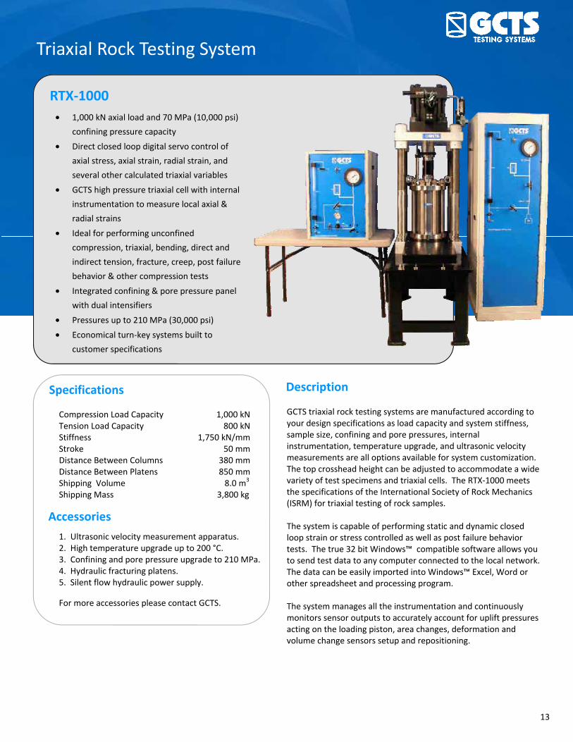
Triaxial Rock Testing System
RTX-1000 • 1,000 kN axial load and 70 MPa (10,000 psi)
confining pressure capacity
• Direct closed loop digital servo control of
axial stress, axial strain, radial strain, and
several other calculated triaxial variables
• GCTS high pressure triaxial cell with internal
instrumentation to measure local axial &
radial strains
• Ideal for performing unconfined
compression, triaxial, bending, direct and
indirect tension, fracture, creep, post failure
behavior & other compression tests
• Integrated confining & pore pressure panel
with dual intensifiers
• Pressures up to 210 MPa (30,000 psi)
• Economical turn-key systems built to
customer specifications
Specifications
Compression Load Capacity 1,000 kN Tension Load Capacity 800 kN Stiffness 1,750 kN/mm Stroke 50 mm Distance Between Columns 380 mm Distance Between Platens 850 mm Shipping Volume 8.0 m3 Shipping Mass 3,800 kg
Accessories
1. Ultrasonic velocity measurement apparatus. 2. High temperature upgrade up to 200 °C. 3. Confining and pore pressure upgrade to 210 MPa. 4. Hydraulic fracturing platens. 5. Silent flow hydraulic power supply.
For more accessories please contact GCTS.
Description
GCTS triaxial rock testing systems are manufactured according to your design specifications as load capacity and system stiffness, sample size, confining and pore pressures, internal instrumentation, temperature upgrade, and ultrasonic velocity measurements are all options available for system customization. The top crosshead height can be adjusted to accommodate a wide variety of test specimens and triaxial cells. The RTX-1000 meets the specifications of the International Society of Rock Mechanics (ISRM) for triaxial testing of rock samples. The system is capable of performing static and dynamic closed loop strain or stress controlled as well as post failure behavior tests. The true 32 bit Windows™ compatible software allows you to send test data to any computer connected to the local network. The data can be easily imported into Windows™ Excel, Word or other spreadsheet and processing program. The system manages all the instrumentation and continuously monitors sensor outputs to accurately account for uplift pressures acting on the loading piston, area changes, deformation and volume change sensors setup and repositioning.

14 www.gcts.com
Triaxial Rock Testing System
RTX-1500 • Direct closed loop digital servo control of
axial stress, axial strain, radial strain, and
several other calculated triaxial variables
• Standard 1,500 kN axial load capacity and
1,750 kN/mm stiffness
• GCTS high pressure triaxial cell with internal
instrumentation to measure local axial &
radial strains
• 140 MPa servo controlled pressure
intensifier system for cell and pore pressure
• Available options: axial & circumferential
deformation measurement system, platens
with ultrasonic transducers, and high
temperature control system
• Pressures up to 210 MPa (30,000 psi)
• Economical turn-key systems built to
customer specifications
Specifications
Compression Load Capacity 1,500 kN Tension Load Capacity 820 kN Stiffness 1,750 kN/mm Stroke 50 mm Distance Between Columns 400 mm Distance Between Platens 800 mm Shipping Volume 8.0 m3 Shipping Mass 3,900 kg
Accessories
1. Ultrasonic velocity measurement apparatus. 2. High temperature upgrade up to 200 °C. 3. Confining and pore pressure upgrade to 210 MPa. 4. Hydraulic fracturing platens. 5. Silent flow hydraulic power supply.
For more accessories please contact GCTS.
Description
GCTS triaxial rock testing systems are manufactured according to your design specifications as load capacity and system stiffness, sample size, confining and pore pressures, internal instrumentation, temperature upgrade, and ultrasonic velocity measurements are all options available for system customization. The top crosshead height can be adjusted to accommodate a wide variety of test specimens and triaxial cells. The RTX-1500 meets the specifications of the International Society of Rock Mechanics (ISRM) for triaxial testing of rock samples. The system is capable of performing static and dynamic closed loop strain or stress controlled as well as post failure behavior tests. The true 32 bit Windows™ compatible software allows you to send test data to any computer connected to the local network. The data can be easily imported into Windows™ Excel, Word or other spreadsheet and processing program. The system manages all the instrumentation and continuously monitors sensor outputs to accurately account for uplift pressures acting on the loading piston, area changes, deformation and volume change sensors setup and repositioning.

15
Triaxial Rock Testing System
RTX-3000 • 3,000 kN axial load and 70 MPa (10,000 psi)
confining pressure capacity
• Direct closed loop digital servo control of
axial stress, axial strain, radial strain, and
several other calculated triaxial variables
• GCTS high pressure triaxial cell with internal
instrumentation to measure local axial &
radial strains
• Ideal for performing unconfined
compression, triaxial, bending, direct and
indirect tension, fracture, creep, post failure
behavior & other compression tests.
• Integrated confining & pore pressure panel
with dual intensifiers
• Pressures up to 210 MPa (30,000 psi)
• Economical turn-key systems built to
customer specifications
Specifications
Compression Load Capacity 3,000 kN Tension Load Capacity 1,000 kN Stiffness 500 kN/mm Stroke 50 mm Distance Between Columns 410 mm Distance Between Platens 600 mm Shipping Volume 9.0 m3 Shipping Mass 4,500 kg
Accessories
1. Ultrasonic velocity measurement apparatus. 2. High temperature upgrade up to 200 °C. 3. Confining and pore pressure upgrade to 210 MPa. 4. Hydraulic fracturing platens. 5. Silent flow hydraulic power supply.
For more accessories please contact GCTS.
Description
GCTS triaxial rock testing systems are manufactured according to your design specifications as load capacity and system stiffness, sample size, confining and pore pressures, internal instrumentation, temperature upgrade, and ultrasonic velocity measurements are all options available for system customization. The top crosshead height can be adjusted to accommodate a wide variety of test specimens and triaxial cells. The RTX-3000 meets the specifications of the International Society of Rock Mechanics (ISRM) for triaxial testing of rock samples. The system is capable of performing static and dynamic closed loop strain or stress controlled as well as post failure behavior tests. The true 32 bit Windows™ compatible software allows you to send test data to any computer connected to the local network. The data can be easily imported into Windows™ Excel, Word or other spreadsheet and processing program. The system manages all the instrumentation and continuously monitors sensor outputs to accurately account for uplift pressures acting on the loading piston, area changes, deformation and volume change sensors setup and repositioning.

16 www.gcts.com
Rock Creep Testing System
RCT-2000 • 2,000 kN axial load capacity
• Air operated
• Battery operated data acquisition
• Adjustable crosshead design
• Accepts GCTS high pressure triaxial cell &
other testing components
• Ideal for performing long term loading
tests
• Economical turn-key systems built to
customer specifications
Specifications
Compression Load Capacity 2,000 kN Stiffness 700 kN/mm Stroke 100 mm Distance Between Columns 400 mm Distance Between Platens 600 mm
Accessories
1. Ultrasonic velocity measurement apparatus. 2. High pressure triaxial cell. 3. Confining and pore pressure upgrade. 4. Hydraulic fracturing platens.
For more accessories please contact GCTS.
Description
GCTS RCT-2000 Rock Creep Testing System is designed for performing long term tests without requiring a continued power input. It operates with only 700 kPa (100 psi) air pressure with minimal flow. This system can operate for several days without power, using a compressor with a large tank. The RCT-2000 includes a load and deformation digital indicators as well as an analog gage to read the applied load. Software and a USB based data acquisition are also provided to easily interface with a laptop for recording test data. On-specimen deformation instrumentation can also be provided as well as triaxial cells and other testing components.

17
Pressure Intensifier System
HPVC-070/140/210 • Closed loop digital servo control of pressure or
flow (volume) with bump-less transfer
• 210 MPa (30,000 psi) pressure range
• 500 cm3 stroke capacity
• Stainless steel construction
• Can be used as a volume change measurement
device for triaxial and permeability testing
• Larger pressure and volume stroke capacities
also available
Specifications
Control Precision Better than ± 0.1 MPa (15 psi) Pressure Transducer Resolution 0.02 MPa Volume Transducer Resolution 0.01 cc Analog Pressure Test Gage Accuracy ± 0.25% Fluid Media Compatibility oil and water Fluid Reservoir Capacity 19 liter (5 gallon) Required Pressure Input 21 MPa (3,000 psi)
Description
GCTS pressure intensifiers are ideal for the servo control of the cell pressure in triaxial tests, head pressure in permeability tests, or fluid pressure in hydro-fracture tests. This intensifier can also be used to measure flow in permeability tests and volume change in triaxial tests while applying prescribed pressures. Together with GCTS digital servo controller and the triaxial software, it allows the performance of more advanced tests such as stress/strain path. The HPVC system is mounted in a metal cabinet on casters to house the confining pressure/volume servo controlled intensifier, fluid reservoir, sight level gage, and venturi vacuum pump. All valves are mounted on the front panel for easy intensifier operation and filling or draining the cell. GCTS makes a dual piston intensifier model for tests where continuous flow is required and pressure spikes cannot be tolerated. These models include two intensifiers and two servo valves together with the necessary check valves, plumbing, and special control software for automatic operation. Also available, as an alternative, is an economical air/oil pressure booster. These units operate with 700 kPa (100 psi) air pressure input for a 70 MPa (10,000 psi) output. GCTS pressure boosters offer a low cost, trouble free operation and are ideal for use in creep and sustained loading in long term tests.
Shipping
Mass: 285 kg Dimensions: 0.85 m x 0.85 m x 2.0 m (WxDxH)
HPVC pressure intensifier.

18 www.gcts.com
Quick High Pressure Triaxial Cell
HTRX-010 • 70 MPa (10,000 psi) pressure & 500 kN
(100 kips) axial load capacity
• Quick “drop-in” specimen setup
• Axial and radial strain measurements
• Upper platen provided with a spherical seat to
compensate for non-parallel specimen ends
• Hardened stainless steel construction
• Bottom pore pressure plumbing provided for effective
stress measurements
• Includes triaxial software and automatic data acquisition
with USB interface
• Accepts samples with a diameter from 25 mm to 54 mm
(NX) and with a length of 2 times the diameter (one
different set of platens and membrane retainer is
required for each size)
Specifications
Pressure Capacity 70 MPa Specimen Diameter Up to 54.7 mm Material Stainless steel Inside Diameter 67 mm Overall Height 300 mm
Accessories 1. Manual load frame for axial load application. 2. Specimen platens up to 54.7 mm diameter. 2. Panel for application of cell pressure.
For more accessories please contact GCTS.
Description
The GCTS Quick Triaxial Cell was designed for fast and easy testing of rock cores with diameters from 25 mm to 54.7 mm (NX). The triaxial cell has a membrane built-in where specimens are simply dropped inside from the top. Three lateral actuators instrumented with LVDTs that are pressure-compensated ensure a firm contact with the specimen to precisely measure the radial strains. The LVDTS eliminate the time-consuming task of gluing strain gages onto the specimen to measure radial strains. Axial strains are measured with two averaging vertical LVDTs. GCTS offers economical loading frames that are manually operated (hand pump) to apply axial loads up to 500 kN. The HTRX-010 triaxial cell fits inside the GCTS Point Load tester frame. GCTS also offers several different pumps (manual and automated) for applying the cell pressure. The complete system (triaxial cell, loading frame, and data acquisition) fits inside a carrying case. The included automatic data acquisition with USB interface allows the connection to a Laptop or PC computer for real time display of stress-strain curves. The HTRX-010 is ideal for the classroom.

19
High Pressure Triaxial Cells
HTRX-070/140/210 • Pressure capacity: 70, 140 and 210 MPa
• Stainless steel construction
• Accepts samples with a diameter from 25 mm
to 100 mm with length of 2 times the diameter
• Upper platen provided with a spherical seat to
compensate for non-parallel specimen ends
• Top & bottom pore pressure plumbing
provided for effective stress and permeability
measurements
• Electrical feed through connectors for GCTS
axial and circumferential deformation
measurement devices, ultrasonic sensors, and
other special transducers
• Built to customer specifications
• Hydraulic balance option available for each cell
Specifications
Pressure Capacity Up to 210 MPa Specimen Diameter Up to 100 mm Material Stainless steel Temperature Rating 200 °C
Accessories
1. Ultrasonic velocity measurement platens. 2. Axial and circumferential deformation package. 3. High & low temperature control subsystem. 4. Hydraulic lift and locking.
Description
The GCTS high pressure triaxial cells were designed for testing rock specimens with diameters up to 100 mm (4 inch) and 200 mm (8 inch) lengths at confining pressures of up to 210 MPa and axial loads of up to 4,500 kN. Other specimen diameters can also be tested with the use of optional platens. The 150 mm inside diameter of the cell wall and the electrical feed through connectors installed at the cell base allow the use of in-vessel instrumentation for precise measurements of deformation modulus and Poisson’s ratio. The standard specimen platens have o-ring grooves for sealing the specimen jacket and an upper spherical seat to minimize stress concentrations due to non-parallel specimen ends. Pore fluid lines and ports for both, upper and lower platens, are also standard for effective stress and permeability measurements. Cell and pore fluid connectors are provided at the cell base for easy interface with either the GCTS computer servo controlled pressure intensifier or the GCTS air/oil pressure booster system. A loading piston with spherical seating is also provided with this triaxial cell. The typical trixial cell includes 4 electrical feed through connectors with 4 lines each (16 electrical lines total) to connect a variety of internal sensors such as deformation gauges, P & S wave velocity transducers and acoustic emission sensors. Additional feed throughs can be supplied.
Automatic cell assembly.

20 www.gcts.com
GCTS Rock Triaxial Cells
HTRX-070
HTRX-010
Pressure capacity: 70 MPa (10,000 psi)
Internal diameter (ID): 67 mm (2.5 in)
Overall width: 220 mm (8.7 in)
Overall height: 300 mm (11.8 in)
Mass: 18 kg (40 lbf)
Max. specimen size with internal instrumentation:
Diameter: 54.7 mm (2.125 in) Height: 108 mm (4.25 in)
Specifications
Specifications
HTRX-070L Specifications
Pressure capacity: 70 MPa (10,000 psi)
Internal diameter (ID): 127 mm (5 in)
Overall width: 355 mm (14 in)
Overall height: 495 mm (19.5 in)
Mass: 111 kg (245 lbf)
Max. specimen size with internal instrumentation:
Diameter: 54.7 mm (2.125 in) Height: 108 mm (4.25 in)
Pressure capacity: 70 MPa (10,000 psi)
Internal diameter (ID): 178 mm (7 in)
Overall width: 387 mm (15.25 in)
Overall height: 559 mm (22 in)
Mass: 135 kg (298 lbf)
Max. specimen size with internal instrumentation:
Diameter: 100 mm (4 in) Height: 200 mm (8 in)

21
GCTS Rock Triaxial Cells HTRX-140
HTRX-210
Specifications
Specifications
HTRX-140XL Specifications
Pressure capacity: 140 MPa (20,000 psi)
Internal diameter (ID): 152 mm (6 in)
Overall width: 336 mm (13.25 in)
Overall height: 527 mm (20.75 in)
Mass: 119 kg (262 lbf)
Max. specimen size with internal instrumentation:
Diameter: 76 mm (3 in) Height: 152 mm (6 in)
Pressure capacity: 140 MPa (20,000 psi)
Internal diameter (ID): 178 mm (7 in)
Overall width: 482 mm (19 in)
Overall height: 603 mm (23.75 in)
Mass: 248 kg (546 lbf)
Max. specimen size with internal instrumentation:
Diameter: 100 mm (4 in) Height: 200 mm (8 in)
Pressure capacity: 210 MPa (30,000 psi)
Internal diameter (ID): 152 mm (6 in)
Overall width: 419 mm (16.5 in)
Overall height: 520 mm (20.5 in)
Mass: 278 kg (612 lbf)
Max. specimen size with internal instrumentation:
Diameter: 76 mm (3 in) Height: 152 mm (6 in)
22 www.gcts.com
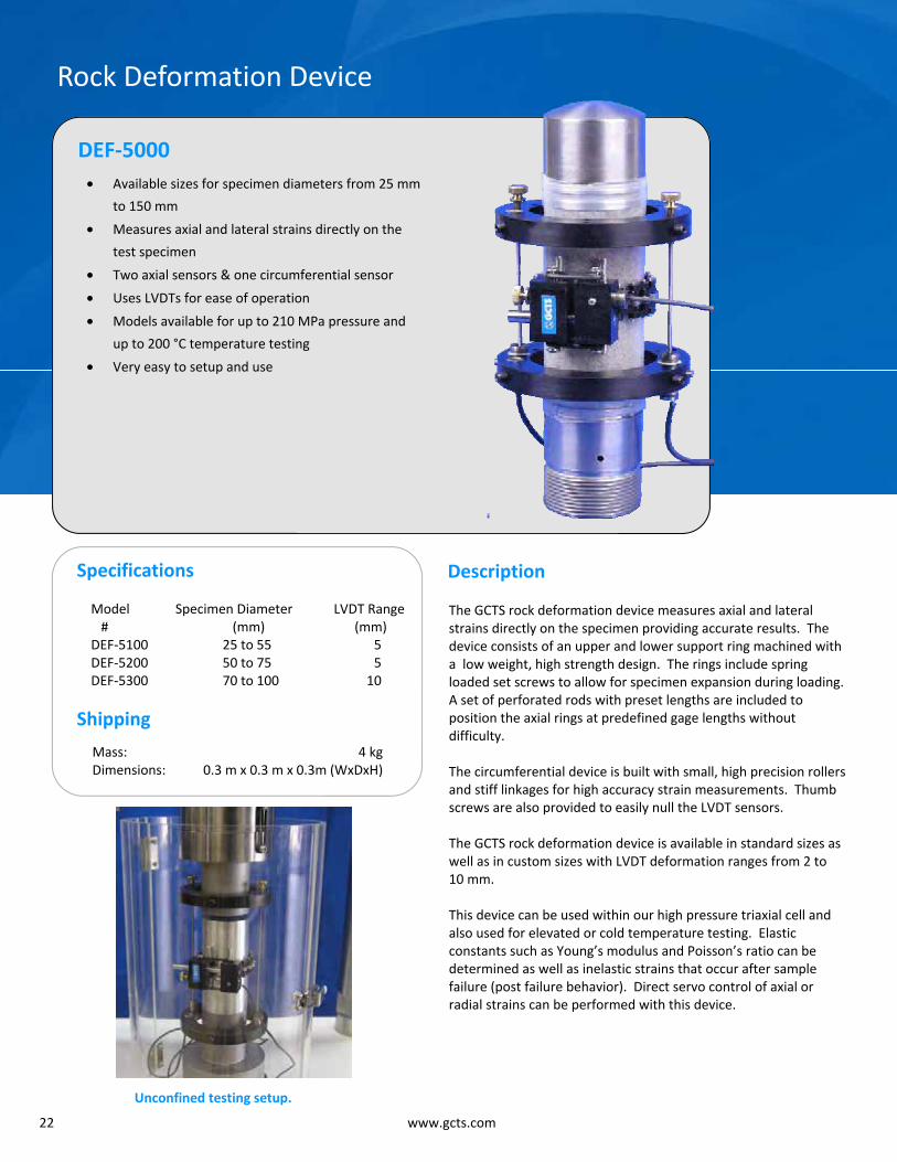
Rock Deformation Device
DEF-5000 • Available sizes for specimen diameters from 25 mm
to 150 mm
• Measures axial and lateral strains directly on the
test specimen
• Two axial sensors & one circumferential sensor
• Uses LVDTs for ease of operation
• Models available for up to 210 MPa pressure and
up to 200 °C temperature testing
• Very easy to setup and use
Specifications
Model Specimen Diameter LVDT Range # (mm) (mm) DEF-5100 25 to 55 5 DEF-5200 50 to 75 5 DEF-5300 70 to 100 10
Description
The GCTS rock deformation device measures axial and lateral strains directly on the specimen providing accurate results. The device consists of an upper and lower support ring machined with a low weight, high strength design. The rings include spring loaded set screws to allow for specimen expansion during loading. A set of perforated rods with preset lengths are included to position the axial rings at predefined gage lengths without difficulty. The circumferential device is built with small, high precision rollers and stiff linkages for high accuracy strain measurements. Thumb screws are also provided to easily null the LVDT sensors. The GCTS rock deformation device is available in standard sizes as well as in custom sizes with LVDT deformation ranges from 2 to 10 mm. This device can be used within our high pressure triaxial cell and also used for elevated or cold temperature testing. Elastic constants such as Young’s modulus and Poisson’s ratio can be determined as well as inelastic strains that occur after sample failure (post failure behavior). Direct servo control of axial or radial strains can be performed with this device.
Shipping
Mass: 4 kg Dimensions: 0.3 m x 0.3 m x 0.3m (WxDxH)
Unconfined testing setup.

23
Differential Strain Curve Analysis Measurement Device
DSA-12 • Measurement device for Differential Strain Curve
Analysis (DSCA)
• Includes twelve (12) high pressure LVDT sensors for
strain measurement
• Support base and LVDT holders with anodized high
quality aluminum construction
• Stainless steel sliding rail for fast and precise
positioning of sensors onto the samples with
different dimensions
• Interchangeable flat or pointed LVDT ends for
suitable contact with the specimen
• Accommodates cubical rock samples with
maximum dimensions of 50 mm x 50 mm x 50 mm
• Optional hydrostatic high pressure triaxial cell with
pressure capacity of 140 MPa (20,000 psi)
• Requires signal conditioning and data acquisition
unit for the sensors
Specifications
Pressure Capacity Up to 140 MPa Specimen Dimensions 50 x 50 x 50 (mm) cube Number of LVDTs 12 Material Anodized aluminum Shipping Mass 2 kg
Description
The GCTS differential strain curve measurement device (DSA-12) is designed for testing cubical rock specimens under hydrostatic conditions in order to determine the in-situ stress state. The results obtained using the DSA-12 allow for characterization of, amongst other parameters, the distribution of crack porosity with crack closure pressure as well as the crack orientation as a function of crack closure pressure. The DSA-12 comes with twelve high precision LVDTs vented for pressures up to 140 MPa with cables to connect to electrical feed throughs inside the triaxial cell. GCTS offers the hydrostatic triaxial cell (HTRX-DSA) with 140 MPa pressure capacity. HTRX-DSA features stainless steel construction with 16 feed through lines, 4 clusters of 4 lines, for in-vessel instrumentation, 3 fluid pressure connectors (cell, drainage and bleed ports), 100 mm (4 inch) inside diameter. HTRX-DSA accommodates DSA-12 device with the 12 LVDTs and 50 mm x 50 mm x 50 mm cubical rock specimens. For pricing information please contact us at [email protected].
Accessories
1. HTRX-DSA high pressure hydrostatic/triaxial cell. 2. Signal conditioning and data acquisition unit.

24 www.gcts.com
Fast Pulse Decay Permeability Apparatus
HPPD-20 • Apparatus for measurement of rock
permeability using the Fast Pulse Decay method
• Two (2) 2,000 cc volume stainless steel
reservoirs
• Two (2) 500 cc volume stainless steel reservoirs
• Nine (9) zero volume change ball valves
• Two (2) pressure transducers
• 20 MPa pressure capacity
• Integrated temperature control system inside
the cabinet
Description
The GCTS Fast Pulse Decay Permeability Apparatus (HPPD-20) is designed for measurement of permeability in micro-porous material such as a gas shale and other reservoir rock, in order to determine the capacity and flow characteristics of the rock matrix. HPPD-20 is capable of measuring rock permeability less than 1 μD (microdarcy). HPPD-20 includes two large stainless steel reservoirs with 2,000 cc volume capacity each and two smaller stainless steel reservoirs each with 500 cc volume capacity. Also included are nine zero volume change ball valves and one needle valve for precise flow control. The system components are secured in an insulated metal cabinet with front panel mounted valves and controls. The system also features precise temperature control inside the cabinet for elimination of any errors from temperature induced volume expansion or contraction of the fluid and gas inside the reservoirs. HPPD-20 includes all necessary valves and fluid lines to perform the Fast Pulse Decay permeability tests when used with any of the GCTS triaxial systems.
HPPD-20 system schematic.

25
Rock Abrasiveness Apparatus
RAA-100 • Measurement apparatus for determination of rock
abrasiveness as specified by the Cerchar test
• Meets ASTM D7625 specifications
• Precision slide for smooth movement with
graduated knob for accurate scratch distance
control with 0.01 mm precision
• Includes one hundred (100) sharp steel indenters
with hardness of 200 kg/mm2 and 90° cone angle
according to Cerchar test
• Steel block crosshead with stainless steel linear ball
bearings for easy application of required 70 N force
• Accepts specimens with maximum width of 76 mm
(3 in) and 150 mm height (6 in)
• Rock holding vice with anodized aluminum jaws for
firm no-slip grip during the test
Specifications
Specimen Diameter Up to 100 mm (4 inch) Apparatus Material Anodized aluminum, steel Shipping Mass 20 kg
Description
The GCTS Rock Abrasiveness Apparatus (RAA-100) is used for measurement of rock abrasiveness under the standards specified by the Cerchar test. The test consists of measuring the wear flat on the standard steel indenter with 200 kg/mm2 hardness loaded with 70 N force, after it has scratched 10 mm distance on the rock surface. The indenter is examined under the microscope and the amount of wear is correlated to the Cerchar Abrasiveness Index (CAI). RAA-100 features precision slide for smooth movement of the rock specimen over the required scratch distance. It also comes with graduated knob for accurate scratch distance control with 0.01 mm precision. The slide movement is controlled with precision threaded acme rod with 1 mm pitch (1 mm horizontal movement per knob revolution). Included in the RAA-100 package are one hundred (100) sharp steel indenters with 200 kg/mm2 hardness and 90° cone angle, rock holding vise and anodized aluminum and stainless steel construction loading frame.
Accessories
1. Microscope. 2. Steel indenters.

27
Circumferential Velocity Apparatus
CVA-100 • Measurement of P-wave and S-wave velocities with
the included transducers
• Map of P-wave and S-wave velocities vs.
orientation angle
• Includes turntable with vernier scale for precise
measurement of angular orientation of the
specimen
• Pneumatic actuators for automatic clamping of
sensors onto specimen
• 200 kHz or 1 MHz frequency crystals, other
frequencies available upon request
• 100 mm (4 inch) maximum specimen diameter
• Very easy to setup and use
• Requires GCTS ULT-100 ultrasonic velocity system
or any other suitable ultrasonic measurement
device
Specifications
Specimen Diameter Up to 100 mm (4 inch) Crystal Frequency 200 kHz (other available) Material Anodized aluminum, steel Shipping Mass 20 kg Shipping Dimensions 40 x 32 x 30 (cm) HxWxL
Description
The GCTS Circumferential Velocity Anisotropy Apparatus (CVA-100) is used to determine the compression P-wave velocities and shear S-wave velocities of rock core specimens in different orientations. This apparatus, when used with a GCTS ULT-100 or a suitable ultrasonic measurement device, can obtain the velocity versus angle and height data with relative ease and precision. CVA-100 comes standard with set of 200 kHz P-wave and S-wave measurement platens (other crystal frequencies available upon request). The apparatus frame (base, columns and the transducer supports) is built using high quality anodized aluminum, which supports the steel turntable with a precision vernier scale and fasteners capable of accommodating 100 mm (4 inch) diameter specimens. Pneumatic actuators are included, with return toggle switch, for quick and easy positioning of the transducers on the specimen. The pneumatic actuators come with air lines and quick-connect fittings for a compressed air input.
Accessories
1. ULT-100 ultrasonic velocity measurement system. 2. Ultrasonic velocity platens with 1 MHz crystals.

28 www.gcts.com
Rock Polyaxial (True Triaxial) Fixture
RPX-150 • Stainless steel construction
• Perform polyaxial (true triaxial) tests within GCTS
rock triaxial cells
• Independent control of σ1, σ2, σ3 (where σ1 ≠ σ2 ≠ σ3)
or ε1, ε2, ε3 or a combination of stress or strain
control for each axis
• Measures strains in all three orthogonal directions
• Accommodates cubical or cylindrical rock specimens
with maximum dimensions of 38.1 mm x 38.1 mm x
76.2 mm or 38.1 mm diameter by 76.2 mm height
• Stress control up to 140 MPa
• Available ultrasonic sensors to measure P and S wave
velocities under different stress states
• Optional hydraulic fracturing platens available to
perform wellbore stability tests
• Customized fixtures available to fit existing triaxial
cells
• GCTS also offers stand-alone, large scale polyaxial
systems built to customer specifications
Specifications
Specimen Diameter 38.1 mm (1.5inch) Pressure Capacity 140 MPa (20,000 psi) Material Stainless steel Shipping Mass 25 kg Shipping Dimensions 40 x 32 x 30 (cm) HxWxL
Description
The GCTS RPX-150 Rock Polyaxial fixture can be used to study the intermediate principal stress effect on rock engineering behavior and describe adequately the strength of rock under a general system of polyaxial compressive stresses. The RPX-150 is a simple and economical fixture that enhances the capabilities of standard GCTS rock triaxial systems which include cell and pore pressure control. This fixture is designed to fit inside GCTS triaxial cells and use the load frame to (typically) apply σ1, the cell pressure to apply σ2 and the pore pressure system to apply σ3 through the fixture’s flat jacks. GCTS also offers semi-circular platens to test cylindrical specimens together with GCTS hydraulic fracturing fixtures and approximate the effects of anisotropic stress state on borehole stability. Although the stress state applied with these semicircular loading jacks is not uniform, it is much easier to prepare and test cylindrical specimens. Ultrasonic sensors can be provided to study the effects of anisotropic stress conditions on compression and shear wave velocities. Velocities for all three axes can easily be measured during polyaxial tests with this option.
Accessories
1. ULT-100 ultrasonic velocity measurement system. 2. Hydraulic fracturing platens.

29
Hydraulic Fracture Test Fixture
HTRX-HF • Perform hydraulic fracture, wellbore stability
and rock permeability tests within GCTS rock
triaxial systems
• Available fixtures for specimens from 25 mm
(1 inch) up to 100 mm (4 inch) diameter
• Optional internal acoustic emission sensors
• Large scale hydraulic fracturing equipment
available
Specifications
Model Number Specimen Diameter HTRX-HF-1.0 25 mm (1 inch) HTRX-HF-1.5 38 mm (1.5 inch) HTRX-HF-BX 42 mm (1.65 inch) HTRX-HF-2.0 51 mm (2 inch) HTRX-HF-NX 54 mm (2.125 inch) HTRX-HF-3.0 76 mm (3 inch) HTRX-HF-4.0 102 mm (4 inch)
Description
The GCTS hydraulic fracture fixture allows for the performance of fracture tests within any of the standard GCTS rock triaxial cells and the use of a GCTS HPVC pressure intensifier. This fixture is typically used for hydraulic fracture, wellbore stability, and permeability tests. Tests can be performed with or without confining pressure. Typically, fracturing pressure is ramped up at a constant fluid injection rate while injection pressure and radial strain are measured to determine the fracture stress. When coupled with GCTS Acoustic Emissions (AE) system, it is possible to graph the AE versus the internal pressure to better detect the onset of fracturing. Any of GCTS rock triaxial systems can be supplied or upgraded with hydraulic fracturing test fixture, further enhancing its capabilities with minimal cost. Each specimen diameter requires a specific fracturing fixture constructed for that specific sample diameter.
Fractured specimen after test.
35
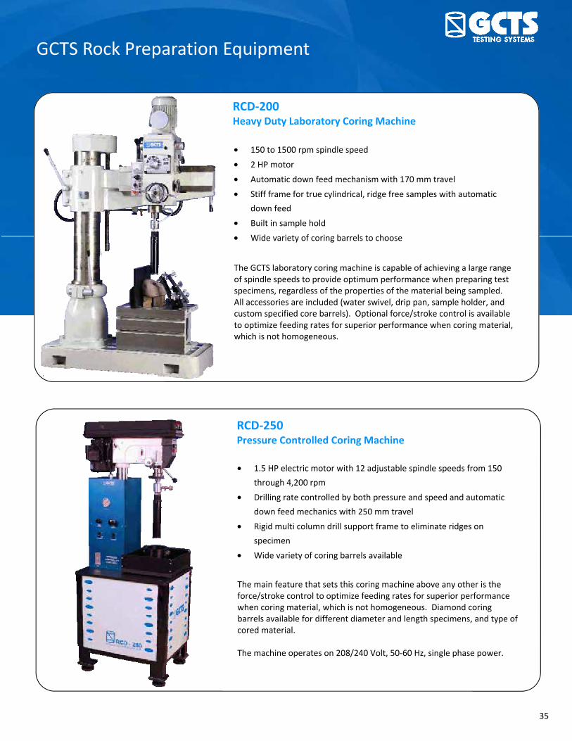
GCTS Rock Preparation Equipment
• 150 to 1500 rpm spindle speed
• 2 HP motor
• Automatic down feed mechanism with 170 mm travel
• Stiff frame for true cylindrical, ridge free samples with automatic
down feed
• Built in sample hold
• Wide variety of coring barrels to choose
RCD-200 Heavy Duty Laboratory Coring Machine
The GCTS laboratory coring machine is capable of achieving a large range of spindle speeds to provide optimum performance when preparing test specimens, regardless of the properties of the material being sampled. All accessories are included (water swivel, drip pan, sample holder, and custom specified core barrels). Optional force/stroke control is available to optimize feeding rates for superior performance when coring material, which is not homogeneous.
RCD-250 Pressure Controlled Coring Machine
• 1.5 HP electric motor with 12 adjustable spindle speeds from 150
through 4,200 rpm
• Drilling rate controlled by both pressure and speed and automatic
down feed mechanics with 250 mm travel
• Rigid multi column drill support frame to eliminate ridges on
specimen
• Wide variety of coring barrels available
The main feature that sets this coring machine above any other is the force/stroke control to optimize feeding rates for superior performance when coring material, which is not homogeneous. Diamond coring barrels available for different diameter and length specimens, and type of cored material. The machine operates on 208/240 Volt, 50-60 Hz, single phase power.

36 www.gcts.com
GCTS Rock Preparation Equipment
• Fast grinder with a single-pass full specimen coverage to make core
loading faces parallel and flat according to ASTM and ISRM
specifications.
• 2 HP motor
• Includes diamond grinding cup wheel, coolant system with 45 liters of
biodegradable rock oil
• Custom made specimen holder
RSG-200 Rock Specimen Grinder
The GCTS specimen grinder provides the final step to preparing test specimens with parallel and flat ends according to ASTM and ISRM specifications. The grinder is driven by a heavy duty 2 HP electric motor for durability. A diamond grinding cup wheel is provided along with a custom stainless steel sample holder. GCTS offers sample holders for specimen diameters from 25 mm to 150 mm. The system has a built-in cooling circulator that cools the grinding cup wheel when preparing a specimen.
RLS-100 Specimen Lab Saw
• 3 speed advancing rate (feed rate of specimen being prepared)
• Accepts up to 170 mm diameter core specimen
• 1 horsepower electric motor (3 HP available)
• Stainless steel upgrade available
• Metal hood with viewing window
RLS-100 has a power feed feature, which automatically pushes the specimen into the saw blade for an even, smooth cut. The lab saw can accommodate up to 170 mm diameter specimen. The blade speed is approximately 800 rpm and it is cooled either by water or biodegradable cutting oil. The machine operates on 208/240 Volt, 50-60 Hz, single phase power.

Product Overview
Soil Testing Systems ............................................................................................... 4 Direct Shear Testing System for Soils (SDS-100/150) .............................................................................. 4 Direct Shear Testing System for Soils and Asphalts (SDS-300) ................................................................ 5 Residual Ring Shear Testing System for Soils (SRS-150) .......................................................................... 6 Static/Dynamic Simple Shear Testing System (SSH-100) ......................................................................... 7 Dynamic Hollow Cylinder Testing System (HCA-100/150) ...................................................................... 8 Large-Scale Dynamic Hollow Cylinder System (HCA-600) ....................................................................... 9 Poly-Axial Testing System (SPAX-2000) ................................................................................................. 10 Resilient Modulus Testing System (MRT-050/100/200/300) ................................................................ 11 Resonant Column/Torsional Shear Testing System (TSH-100/200) ...................................................... 12 Pneumatic Soil Triaxial Testing System (STX-050) ................................................................................. 13 Cyclic/Stress-Path Soil Triaxial System (STX-100/200/300) ................................................................... 14 Large-Scale Cyclic/Stress-Path Soil Triaxial System (STX-600) ............................................................... 15 Extra Large-Scale Cyclic/Stress-Path Soil Triaxial System (STX-2000).................................................... 16 Frozen Soil Triaxial System (FSTX-200) .................................................................................................. 17 Unsaturated Soil Triaxial System (USTX-2000) ...................................................................................... 18 Soil-Water Characteristic Cell (SWC-150) .............................................................................................. 19 Soil Testing Components .................................................................................... 20 Soil Axial Deformation Device (DEF-6100-AXC) ..................................................................................... 20 Soil Circumferential Deformation Device (DEF-SRCP) ........................................................................... 21 Large-Scale Deformation Device (DEF-S1600) ....................................................................................... 22 Soil Triaxial Cell (TRX-100/200/300) ...................................................................................................... 23 Large-Scale Soil Triaxial Cell (TRX-600) .................................................................................................. 24 Unsaturated Soils Triaxial Double Wall Cell (TRX-2C) ............................................................................ 25 Pressure Control Panel (PCP-200) .......................................................................................................... 26 Pressure Panel & Pressure-Volume Controller (PCP-2000) ................................................................... 27 Fredlund Thermal Conductivity Sensor (FTC-100) ................................................................................. 28 Ultrasonic Velocity Measurement System (ULT-100) ............................................................................ 29 Ultrasonic Velocity Sensors .................................................................................................................... 30 Soil Testing Accessories ......................................................................................................................... 31 Software & Electronics ........................................................................................ 33 Digital Signal Conditioning & Control Unit (SCON-1400/1500/3000) ................................................... 33 Advanced Computer Aided Testing Software (CATS-ADV) .................................................................... 34 Application Software Modules……………………………………………………………………..…………………………………..35 App for iPhone & iPad (gTest) ................................................................................................................ 38
4 www.gcts.com
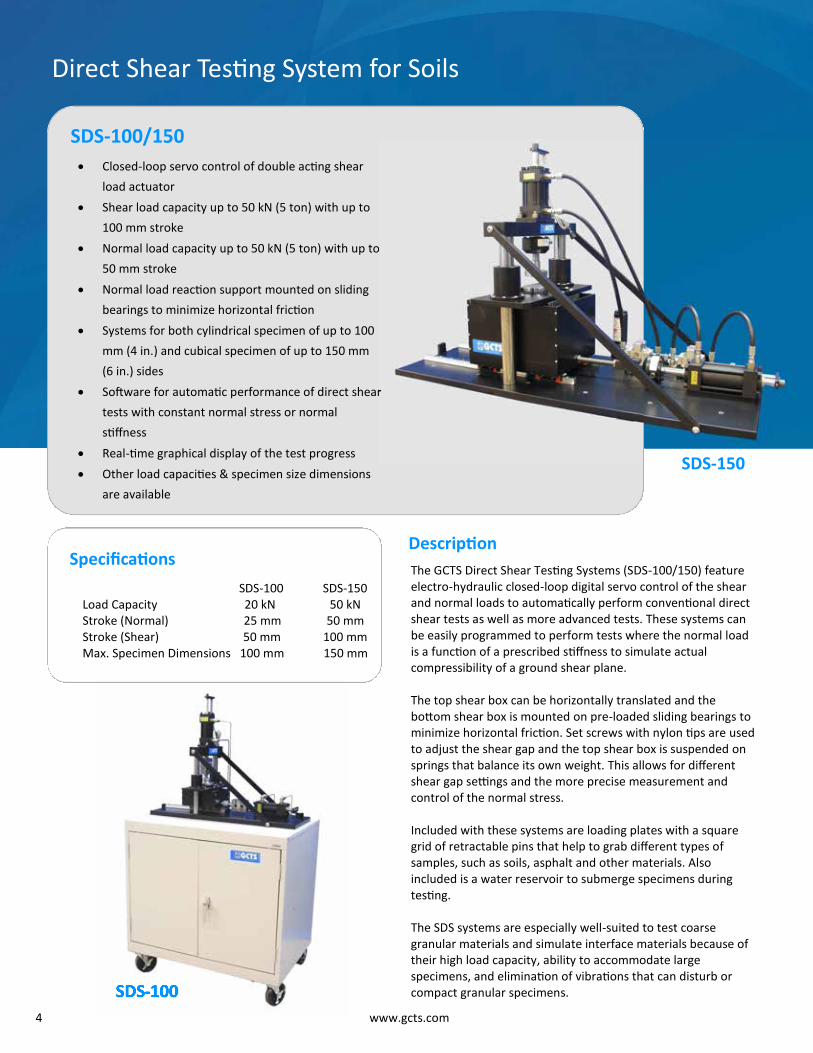
Closed-loop servo control of double acting shear
load actuator Shear load capacity up to 50 kN (5 ton) with up to
100 mm stroke Normal load capacity up to 50 kN (5 ton) with up to
50 mm stroke Normal load reaction support mounted on sliding
bearings to minimize horizontal friction Systems for both cylindrical specimen of up to 100
mm (4 in.) and cubical specimen of up to 150 mm
(6 in.) sides Software for automatic performance of direct shear
tests with constant normal stress or normal
stiffness Real-time graphical display of the test progress Other load capacities & specimen size dimensions
are available
Specifications
SDS-100/150
Direct Shear Testing System for Soils
Description Specifications
SDS-100 SDS-150 Load Capacity 20 kN 50 kN Stroke (Normal) 25 mm 50 mm Stroke (Shear) 50 mm 100 mm Max. Specimen Dimensions 100 mm 150 mm
The GCTS Direct Shear Testing Systems (SDS-100/150) feature electro-hydraulic closed-loop digital servo control of the shear and normal loads to automatically perform conventional direct shear tests as well as more advanced tests. These systems can be easily programmed to perform tests where the normal load is a function of a prescribed stiffness to simulate actual compressibility of a ground shear plane. The top shear box can be horizontally translated and the bottom shear box is mounted on pre-loaded sliding bearings to minimize horizontal friction. Set screws with nylon tips are used to adjust the shear gap and the top shear box is suspended on springs that balance its own weight. This allows for different shear gap settings and the more precise measurement and control of the normal stress. Included with these systems are loading plates with a square grid of retractable pins that help to grab different types of samples, such as soils, asphalt and other materials. Also included is a water reservoir to submerge specimens during testing. The SDS systems are especially well-suited to test coarse granular materials and simulate interface materials because of their high load capacity, ability to accommodate large specimens, and elimination of vibrations that can disturb or compact granular specimens.
Normal load capacity up to 50 kN (5 ton) with up to
Software for automatic performance of direct shear
SDS-150
SDS-100 SDS-100

5
Closed-loop servo control of double acting (push/
pull) 100 kN (10 ton) shear load actuator with 100
mm stroke & 100 kN (10 ton) normal load capacity
with 50 mm stroke Normal load reaction support mounted on sliding
bearings to minimize horizontal friction Accepts 300 mm (12 in.) square specimens Software for automatic performance of direct
shear tests with constant normal stress or normal
stiffness Available interface platens to test soils, asphalt
and geo-membranes Other load capacities & specimen size dimensions
are available, including large-scale test systems for
shear loads of up to 1,000 kN (100 ton)
Specifications
SDS-300
Load Capacity 100 kN shear, 100 kN normal Stroke 100 mm shear, 50 mm normal Max. Specimen Dimensions 300 mm x 300 mm Max. Specimen Height 300 mm
Direct Shear Testing System for Soils and Asphalts
Description
accommodate large specimens, and elimination of vibrations that can disturb or compact granular specimens. Included with this system are loading plates with a square grid of retractable pins that help to grab different types of samples, such as soils, asphalt and other materials. Also included is a water reservoir to submerge specimens during testing. The top shear box can be horizontally translated and the bottom shear box is mounted on sliding bearings to minimize friction. Set screws with nylon tips are used to adjust the shear gap. The top shear box is suspended on springs to balance its weight, causing normal load readings to be extremely accurate. The shear boxes also ensure that shear transfer is done through the top of the shear boxes rather than the sides, making this system the most accurate large-scale direct shear testing system on the market.
The GCTS Direct Shear Testing System for Soils and Asphalts (SDS-300) features electro-hydraulic closed-loop digital servo control of the shear and normal loads for test automation. Loads or deformations for both the shear and normal actuators can be prescribed for automatic performance of conventional direct shear tests as well as more advanced tests. This system can be easily programmed to perform tests such as the constant normal stiffness test where the normal load is a function of a prescribed stiffness for simulating actual compressibility of a ground shear plane (e.g. soil-pile interaction). The SDS-300 is especially well-suited to test coarse granular materials and simulate interface materials because of its high load capacity, ability to SDS-300 Top Shear Box with
Balancing Springs
SDS-150

6 www.gcts.com
Residual Ring Shear Testing System for Soils
SRS-150 Harmonic Drive motor technology for computer-controlled, zero backlash, continuous
rotational speed range from 0.001 to 360 degrees
per minute 300 N-m continuous torque capacity 10 kN axial load capacity 1,000 kPa maximum normal stress 1,300 kPa maximum shear stress Infinite rotational stroke Compact design: loading frame and motor fit inside
the rolling cart for easy specimen preparation Suction control panel to perform unsaturated tests Accepts 150 mm (6 in.) OD & 100 mm (4 in.) ID
annular specimens (98 cm2 effective simple area)
Specifications Load Capacity 10 kN axial load Max. Specimen Diameter 150 mm OD & 100 mm ID Max. Specimen Height 30 mm
Accessories
1. Pressure cell for SRS-150 ring shear apparatus 2. Top and bottom 150 mm OD & 100 mm ID
loading platens for unsaturated soil testing 3. Pressure control panel and pressure chamber
for unsaturated soil testing at suctions up to 1500 kPa
4. Upgrade with optional bender element transducers available
For more accessories, please contact GCTS.
Residual Ring Shear Testing System
Harmonic Drive motor technology for
controlled, zero backlash, continuous
rotational speed range from 0.001 to 360 degrees
m continuous torque capacity
Compact design: loading frame and motor fit inside
the rolling cart for easy specimen preparation
Suction control panel to perform unsaturated tests
Accepts 150 mm (6 in.) OD & 100 mm (4 in.) ID
effective simple area)
Load Capacity 10 kN axial loadMax. Specimen Diameter 150 mm OD & 100 mm IDMax. Specimen Height 30 mm
Description The GCTS Residual Ring Shear Testing System for Soils (SRS-150) is a fully automatic electro-pneumatic and servo-controlled testing system used for determining the drained residual strength of continuously sheared soils. The SRS-150 ring shear apparatus was developed using the Harmonic Drive™ motor technology for a true continuous shearing rate without inherent backlash found in gear assemblies of other ring shear devices. The Harmonic Drive™ shearing actuator allows for a large range of shearing rates at very high resolutions and a large torque capacity. The SRS-150 is capable of applying shearing rates ranging from 0.001 to 360 degrees per minute continuously without backlash for replication of true in-situ strain rates during failure. It is fitted with an electrical slip ring, which allows for unlimited continuous specimen shearing through multiple full rotations to measure the full residual strength. The SRS-150 is capable of performing “multi-stage” tests where a sample is consolidated at a given pressure, sheared to its residual strength, then consolidated to a new pressure and sheared again. This procedure allows for determination of the failure envelope using a single specimen. The device accepts 150 mm OD and 100 mm ID samples for testing granular materials. The system components are conveniently placed inside the rolling cart for mobility and ease of specimen preparation.

7
Static/Dynamic Simple Shear Testing System
SSH-100 Dynamic and static simple shear apparatus capable of
applying cyclic loads up to 30 Hz Digital servo control of shear and normal loads or
displacements Servo control of the confining pressure Acrylic cell capable of 1,000 kPa (150 psi) lateral confining
pressure (2,000 kPa option available) 25 kN normal and shear load capacity Includes platens for static and cyclic triaxial tests Lateral support of top cap to minimize rotation compliance
& sliding base mounted on preloaded linear bearings Software for automatic performance of simple shear and
triaxial tests (static and dynamic) with real-time graphical
display of test progress Automatic tilt mechanism for fast and easy specimen
installation Optional ultrasonic platens for ultrasonic velocity tests Optional HAEV Platens for unsaturated soil testing
Specifications Load Capacity 25 kN shear, 25 kN normal Stroke ± 25 mm Max. Specimen Diameter 100 mm Max. Specimen Height (Simple Shear) 30 mm Max. Specimen Height (Triaxial) 250 mm
Accessories 1. Platens with HAEV disks for unsaturated testing 2. Ultrasonic (compressional and bender element)
sensors and electronics 3. Internal instrumentation for very small strain
measurements 4. Resonant column upgrade 5. 2,000 kPa confining pressure cell available For more accessories, please contact GCTS.
Description The design of the GCTS Simple Shear Testing System (SSH-100) is based on our external cell wall triaxial system. The apparatus has a fixed top and a sliding bottom base mounted on special linear bearings to help with specimen loading and unloading. The system also has a stiff internal support to minimize lateral compliance of the top cap. One of the main advantages of the GCTS Simple Shear Testing System is that the apparatus does not require a reinforced membrane, as lateral support is provided via the confining pressure, which can be servo-controlled. This means that consolidation can be done at K values other than K0. However, this device also includes Teflon-coated thin rings to externally reinforce the standard latex membranes to ensure KO consolidation. The SSH-100 is capable of testing 100 mm (4 in.) and 71 mm (2.8 in.) diameter specimens. Because the internal lateral support is provided by the confining pressure, specimen of different heights can be tested. This means that the system can be used to test either simple shear or triaxial test specimens with heights up to 2.5 times their diameter.

8 www.gcts.com
Dynamic Hollow Cylinder Testing System
HCA-100/150 Closed-loop synchronized digital servo control Complete “turn-key” system Capable of ± 225 N-m torsional loads & ± 100 kN axial loads at up to 30 Hz Confining, back, pore, and internal pressure servo control up to 2,000 kPa Angular displacement sensor with a deflection range of ±25˚ to measure
large shear strains (±40˚ range optional) Non-contacting deformation sensors with a ± 2.5 mm range to detect small
shear strains Software for advanced hollow cylinder and triaxial test procedures Standard systems to test 150 mm OD & 75 mm ID Large scale testing systems also available Optional unsaturated soils testing system package also available Optional internal high-speed torque motor for resonant column testing,
ultrasonic platens, and temperature controller also available
Specifications Description
By providing digital servo control of axial load, torque, confining pressure, internal pressure, and back pressure, the GCTS Dynamic Hollow Cylinder Testing System (HCA-100/150) is capable of subjecting the soil specimen to any stress state and follow any stress/strain path. The HCA-100/150 is capable of simulating most field stress/strain path tests (static or dynamic), including plane strain, simple shear, and small shear strains. Other possible tests include: measurement of dynamic shear strength & deformation, liquefaction potential, shear modulus and damping ratio. The system is versatile in allowing the user to design custom procedures with operating frequencies of up to 30 Hz. The included software automatically calculates up to 28 HCA test parameters in real-time that can be used as control feedback to prescribe an infinite number of stress/strain paths. This includes the principal stress angle (α), allowing the system to easily prescribe the rate and magnitude of the σ1 rotation. The system manages all the instrumentation and continuously monitors sensor outputs to accurately account for uplift pressures acting on the loading piston, area changes, deformation and volume change sensor setup, re-positioning, and more. It also advises the user on how to perform testing tasks and reminds the user of important steps in the test, which helps to minimize the learning time and ensure laboratory personnel can conduct tests with minimal error.
HCA-100 HCA-150 Load Capacity (Axial) 100 kN 100 kN Load Capacity (Torsional) 225 N-m 225 N-m Stroke 75 mm 75 mm Max. Specimen OD 100 mm 150 mm *Standard Specimen ID 63 mm 75 mm Max. Specimen Height 220 mm 330 mm *Other ID Sizes Available
Accessories
1. Platens with HAEV disks for unsaturated testing 2. Ultrasonic (compressional and bender element)
sensors and electronics 3. Internal instrumentation for very small strain
measurements 4. Resonant column upgrade 5. 2,000 kPa confining pressure cell available For more accessories, please contact GCTS.

9
Large-Scale Dynamic Hollow Cylinder System
HCA-600 Complete “turn-key” system Dynamic and Static Hollow Cylinder Apparatus capable of applying
synchronized loading at frequencies up to 10 Hz or single axis loading
at frequencies up to 25 Hz 1,000 N-m torque and ± 300 kN axial load capacity Confining, internal, and back pressure servo control up to 2,000 kPa Angular displacement sensor with a deflection range of ±25° to
measure large shear strains (±40° sensor optional) Realistically imitates all stress path conditions encountered in the field Easily duplicate and control static or dynamic changes in the
magnitude and direction of the principal stresses Study inherent or induced soil anisotropy
Specifications
Load Capacity 300 kN axial, 1,000 N-m torsional Stroke 100 mm Max. Specimen Diam. 300 mm OD & 200 mm ID* Max. Specimen Length 600 mm *Other Dimensions Available
Description The GCTS Large-Scale Dynamic Hollow Cylinder System (HCA-600) is an advanced testing apparatus used for the development of constitutive models and the determination of strength parameters of isotropic and anisotropic soils. It is capable of performing stress path tests with controlled rotation of the principal stress directions. Granular soils with large particles can be tested using this system, as the variation of the radial strain over the wall thickness is negligible for large diameter specimens.
The HCA-600 provides independent control of axial load, torque, confining pressure, inside pressure, and back pressure. All 5 axes can be controlled using feedback from any direct or calculated input, including more than 20 test parameters that are automatically computed by the GCTS software in real-time. The Hollow Cylinder Apparatus is the only device capable of imposing three-dimensional stress states and control the rotation of the principal stress direction. The included software easily allows to realistically imitate in the laboratory the varied stress path conditions encountered in the field. The GCTS program continuously monitors all sensor outputs and calculates all variables during the test, allowing it to accurately account for uplift pressures, dimensional changes, and more. The HCA-600 includes automated valves and controls to automatically perform all test stages, including saturation, consolidation, and shear. Test programs are effortlessly created through a graphical interface that provides advice on how certain tasks should be performed, minimizing learning time and user errors.

10 www.gcts.com
Poly–Axial Testing System
SPAX-2000 Tests rectangular specimens with 75 mm sides and
150 mm in height Capable of applying 5 MPa & 2 MPa as the maximum
major and minor stresses, respectively Independent stress or strain closed-loop digital
servo control of each of the three axes Front and back hinged doors swing open for easy
specimen access Internal load cells are rigidly attached to upper and
side loading platens Especially well-suited for K0 and plane strain testing Complete “turn key” system Systems manufactured to customer specifications Can perform true triaxial test on unsaturated soils
Specifications Max. Major Stress 5 MPa Max. Minor Stress 2 MPa Specimen Side 75mm x 75 mm Specimen Height 150 mm
Accessories 1. Set of non-contracting deformation sensors for
measurement of normal displacements. 2. Ultrasonic velocity measurement system. 3. Special ultrasound platens made to customer
specifications. 4. PCP-2000 Unsaturated upgrade For more accessories, please contact GCTS.
Description The GCTS Poly-Axial Testing System (SPAX-2000) includes four hydraulic load rams, each equipped with LVDT´s for independent computer control of each platen. Stress or strain can be used as the feedback control. With this configuration, the specimen can remain centered, minimizing end platen friction. This is accomplished by controlling the deformation rate of one LVDT on each plane and forcing the opposing LVDT on each plane to mimic the deformation rate of the controlled LVDT. Each of the horizontal loading rams has an internal load cell due to the possibility of end platen friction at the top and bottom porous stones, which is more likely if the specimen exhibits significant non-homogeneity. The load cell on the bottom vertical loading is omitted because the side platens are smooth and can be lubricated, making end platen friction a small issue for this direction. Pore pressure are measured at the top and bottom specimen ends. Stresses and strains in the third direction are applied through chamber fluid pressure. A volume change device is used to measure and control the strains in this direction. Optional proximity sensors can also be used to measure deformations in this direction.

11
Resilient Modulus Testing System
MRT-050/100/200/300 Electro-Hydraulic (Electro-Pneumatic for MRT-050)
Digital Servo Control Complete “turn-key” system Easy to use software for automatic test performance Meets AASHTO, SHRP and ASTM standards Triaxial cells for specimens from 71 mm (2.8 in.) to 150
mm (6 in.) diameter Available indirect tension fixtures to perform ASTM
D4123 and SHRP P-7
Specifications MRT- 050 100 200 300 Load Capacity 14 kN 22 kN 45 kN 100 kN Stroke 50 mm 50 mm 100 mm 100 mm Max. Diameter 75 mm 75 mm 100 mm 150 mm
Max. Height 190 mm 190 mm 250 mm 375 mm
Accessories
1. NCHRP 1-28 specified LVDT CLAMPS 2. Calibration Hardware 3. Additional platens & required sensors for smaller
specimens to meet AASHTO T-307 specifications 4. Unsaturated option for suction controlled tests For more accessories, please contact GCTS.
Description
The GCTS Resilient Modulus software features built in AASTHO, SHRP, and NCHRP test sequences and the capability to specify user-defined sequences. Contact stress is automatically adjusted according to each procedure as selected. Available waveforms include haversine, sine, square and triangular, along with a user-defined waveform selection. Optional peak and valley compensation ensures proper and quick matching of the load parameters. Real-time displays of the prescribed versus actual dynamic load and the dynamic deformation measurements by each sensor are always present. The deformation ratio of the two sensors, Rv (to ensure that the two deformation sensors are in agreement), and resilient modulus, Mr, are also calculated in real-time. During export, curve fitting is done to match the results to models that predict Mr as a function of σm, σd, and cell pressure (CP). Four different functions are calculated automatically, as required by AASHTO and NCHRP procedures. The MRT-300 can test specimens with a 70 mm, 100 mm, or 150 mm diameter, although it is recommended to use a smaller system for 70-mm diameter specimens, such as the GCTS Electro-Pneumatic Resilient Modulus System (MRT-50). All standard systems include the required dual external deformation sensors with supports and internal/external load cell. This GCTS Device is a sound and well-integrated system designed to perform Resilient Modulus tests, as well as standard triaxial (static and dynamic) tests and other, more complex, tests, such as Complex Modulus tests.
The GCTS Resilient Modulus Testing System (MRT Series) boasts a modular design which allows the system to be configured to test soil in a variety of modes. This system is based on the GCTS SCON Digital Signal Conditioning and Controller and can be supplied with a pneumatic or hydraulic loader.
Resilient Modulus Testing System
Triaxial cells for specimens from 71 mm (2.8 in.) to 150
The GCTS Resilient Modulus software features built in AASTHO,

12 www.gcts.com
Resonant Column/Torsional Shear Testing System
TSH-100/200 Capable of performing modulus damping resonant column and
torsional tests on soils and asphalts (both solid and hollow specimens) Easy-to-use software to automatically perform resonant column &
torsional shear tests Floating drive and measurement system to allow for large angular &
axial specimen deformations 1,000 kPa (150 psi) maximum confining pressure. Larger capacities
available upon request using a metallic cell wall Platens with ultrasonic transducers for P- and S-wave velocity
measurements are also available Available loading frame to perform test at anisotropic stress conditions
in addition to conventional static and dynamic tests
Specifications
Accessories 1. Triaxial Loading Frame 2. Platens with compressive and bending elements
for P & S wave velocity 3. Platens with HAEV discs for unsaturated soil
testing For more accessories, please contact GCTS.
Description
system is capable of the full spectrum of modulus measurement, ranging from ultra-low strains to high strains with significant overlap. For the resonant column test, a torsional drive is used to vibrate the top of the soil specimen at first-mode resonance at frequencies of up to 500 Hz while the bottom is fixed. A non-contacting rotational transducer is attached to the top platen monitor the torsional motion directly. The non-contacting sensor is located on extended arms to amplify the rotational deformation and provides a shear strain resolution of 10-6. An optional accelerometer can also be installed to measure large shear strains. The TSH-100/200 can also perform closed-loop torsional shear tests (stress or strain controlled) on the same soil specimen, either statically or dynamically, at up to 50 Hz. With this system, soil specimens can be tested under isotropic (hydrostatic) or anisotropic conditions. The driving and measuring system are mounted on a "floating" frame, which allows large vertical specimen deformations throughout the complete test. Its unique configuration also allows for very large shear deformations of up to ±20°. Standard systems are available for 71 mm and 100 mm diameter specimens. Hollow cylinder platens, molds, and preparation equipment are also available.
Electrical: 110 or 220 VAC / 50-60 Hz (specify when ordering) Sample Diameter Sizes: TSH-100 — 38, 50 & 70 mm TSH-200 — 50, 70 & 100 mm
The Resonant Colum/Torsional Shear Testing System (TSH-100/200) combines the features of both resonant column and torsional shear devices into one elegant system, enabling it to evaluate the effects of a number of soil parameters, such as void ratio, confining pressure, strain amplitude, number of load cycles on shear modulus and material damping. By utilizing all available options, this
Capable of performing modulus damping resonant column and
torsional tests on soils and asphalts (both solid and hollow specimens)
use software to automatically perform resonant column &
Floating drive and measurement system to allow for large angular &
1,000 kPa (150 psi) maximum confining pressure. Larger capacities
wave velocity
Available loading frame to perform test at anisotropic stress conditions
in addition to conventional static and dynamic tests

13
Pneumatic Soil Triaxial Testing System
STX-050 Closed-loop digital servo control Automatically perform saturation,
consolidation & shear stages Static & dynamic loading Stress/strain path Frequencies up to 5 Hertz Affordably priced Optional unsaturated soils testing
system upgrade also available
Specifications Load Capacity 10 kN Stroke 50 mm Max. Specimen Diameter 70 mm Max. Specimen Length 175 mm
Accessories 1. Ultrasonic sensor for P & S wave velocity
measurement 2. Unsaturated soil testing package 3. Resilient Modulus upgrade For more accessories, please contact GCTS.
Description The GCTS Pneumatic Soil Triaxial Testing System (STX-050) is intended for performing conventional triaxial tests as well as more advanced procedures, such as the Ko test and stress/strain path tests. This system also provides the necessary versatility to easily perform dynamic tests for liquefaction, resilient modulus, and cyclic strength. The triaxial testing system includes all of the necessary software modules to perform the above tests. The STX-050 includes an automatic ball valve to automatically perform B-value checks as well as automatically open or close drainage paths as required by different test stages. It incorporates high resolution control of the pneumatic loader, allowing it to obtain clear stress-strain curves and apply load at very low rates. Summary results for individual test specimens can be generated in report format and files can be merged to produce a Mohr envelope plot for up to five specimens. The software will also automatically calculate the shear modulus and hysteretic damping for dynamic tests. Data acquired from all the software modules can be easily transferred to other programs like spreadsheets, databases, etc.

14 www.gcts.com
Cyclic/Stress-Path Soil Triaxial System
STX-100/200/300 Closed-loop digital servo control Specimen diameter from 70 mm to 150 mm Allows both dynamic and static triaxial tests Frequencies up to 30 Hz Electro-hydraulic system Axial loads up to 100 kN Cell pressures up to 2,000 kPa Meets ASTM D-3999 & D-5311 Standards
Specifications Load capacity Stroke Max. Specimen Diam. Max. Specimen Length
Accessories 1. Ultrasonic sensor for P & S wave velocity
measurement 2. Unsaturated soil testing package 3. Resilient Modulus upgrade For more accessories, please contact GCTS.
Description The GCTS Cyclic/Stress-Path Soil Triaxial System (STX-100/200/300) is intended for performing dynamic tests for liquefaction, resilient modulus, cyclic strength, complex modulus, synchronized cyclic axial, confining stress loading and other dynamic triaxial tests. This system also provides the necessary versatility to automatically perform conventional triaxial tests as well as more advanced procedures, such as stress or strain path. The standard STX system includes all the necessary hardware and software to automatically perform all triaxial stages, including saturation and consolidation, and easily create cyclic and static customized test procedures. It allows creation of an unlimited variety of waveforms, including user-generated profiles, such as a digitized earthquake record. The system software provides advice for the user as to how to perform testing tasks and helps the user to select the proper test parameters to automatically execute the desired test. This enables laboratory personnel to perform more complex testing procedures at a substantially lower operating cost with minimal operator error. Standard systems are available for testing specimens with a diameter of 71-mm, 100-mm, and 150-mm. Large-Scale systems are also available.
100 200 300 25 kN 50 kN 100 kN 50 mm 100 mm 100 mm 70 mm 100 mm 150 mm 175 mm 250 mm 375 mm
Specimen diameter from 70 mm to 150 mm
Allows both dynamic and static triaxial tests
5311 Standards

15
Large-Scale Cyclic/Stress-Path Soil Triaxial System
STX-600 Electro-Hydraulic digital servo control
Dynamic and static triaxial tests
Frequencies up to 20 Hz
300 mm specimen diameter
Axial loads up to 1,000 kN
Cell pressures 1,000 kPa
Direct servo control of stress, strain (axial,
radial, volumetric) or any other calculated
variable
Description The GCTS Large-Scale Cyclic Soil Triaxial System (STX-600) is intended for performing dynamic tests on soils with large particle sizes, such as gravely soils and railway ballasts. The triaxial cell accepts 300 mm diameter samples with heights up to 700 mm. This system is typically used to perform tests for liquefaction, resilient modulus, cyclic strength, complex modulus, synchronized cyclic axial, confining stress loading and other dynamic triaxial tests. The STX-600 also provides the necessary versatility to automatically perform conventional triaxial tests as well as more advanced procedures, such as stress or strain path. The standard STX-600 system includes all the necessary hardware and software to automatically perform all triaxial stages, including saturation and consolidation. The user is able to program custom waveforms for testing and can be easily programmed to perform customized testing procedures. The system software advises the user on important testing tasks and is very easy to learn, allowing training time to be minimized while maximizing productivity.
Specifications
Load Capacity 300 kN Stroke 150 mm Max. Specimen Diameter 300 mm Max. Specimen Length 700 mm
Accessories 1. Device for small strain measurement (DEF-1600) 2. Accessories for smaller specimen sizes 3. Dynamic confining pressure for synchronized
dynamic biaxial tests For more accessories, please contact GCTS.
Triaxial System Path Soil

16 www.gcts.com
Extra Large-Scale Soil Triaxial System
STX-2000 Electro-Hydraulic digital servo control
1,000 mm Specimen Diameter
Axial loads up to 3,000 kN
Cell Pressures up to 3,000 kPa
Direct servo control of stress, strain (axial,
radial, volumetric) or any other calculated
variable
Dynamic compaction frame with 200 kN load
capacity and frequencies from 0 to 100 Hz
Description
The STX-2000 includes all hardware needed to create and load a large specimen into the testing chamber without need of a forklift. It also includes a dynamic compaction frame, which can create the specimen using a 200 kN axial load and at frequencies of up to 100 Hz. This system uses an innovative cost-saving and space-saving design with many automation features. This includes an automatic triaxial cell assembly that hydraulically locks the triaxial cell without requiring any tightening of nuts or bolts. The standard STX-2000 system includes all the necessary hardware and software to automatically perform all triaxial stages, including saturation and consolidation. Custom testing procedures can be easily programmed by the user, and an unlimited variety of waveforms can be executed by the system as defined by the user. The program alerts the user to important testing steps that must be performed, minimizing training time while increasing productivity. The triaxial cell included with the STX-2000 system is constructed of stainless steel. The standard unit features a composite, see-through Plexiglas cell wall reinforced with anodized aluminum rings. All the standard GCTS triaxial cells can accommodate smaller diameter specimens using the optional platens and provides the necessary information required to automatically execute the desired test.
Specifications
Load capacity 3,000 kN Stroke 500 mm Max. Specimen Diameter 1,000 mm Max. Specimen Length 2,000 mm
Accessories 1. Compaction split mold/jacket stretcher for different size specimens. 2. Test accessories for custom-sized specimen. For more accessories, please contact GCTS.
The GCTS Extra Large-Scale Soil Triaxial System (STX-2000) is intended for performing tests on soils with large particle sizes, such as rock backfills and gravely soils. The triaxial cell accepts 1,000 mm diameter samples with heights up to 2,000 mm. This system also provides the necessary versatility to automatically perform conventional triaxial tests as well as more advanced procedures, such as stress or strain path. In addition, the STX-2000 has the capability of performing dynamic triaxial tests.
Hydraulic digital servo control
1,000 mm Specimen Diameter
Cell Pressures up to 3,000 kPa
Direct servo control of stress, strain (axial,
radial, volumetric) or any other calculated
Dynamic compaction frame with 200 kN load
capacity and frequencies from 0 to 100 Hz

17
Frozen Soil Triaxial System
FSTX-200 200 kN (44 kips) axial load & 30 MPa
(4350 psi) cell pressure capacity. Larger
capacities available upon request 30 Hz maximum loading frequency Computer temperature control from -20 ˚C (-35 ˚C with LN2) to +150 °C Electro-hydraulic closed-loop digital
servo control Software modules for the performance of
UU, CU, and CD static tests with stress
path control and dynamic tests such as
liquefaction, modulus/damping
measurement, and resilient modulus Optional internal axial & circumferential
deformation measurement system, Optional platens with ultrasonic
transducers for P-and S-wave velocity
measurements
Specifications Load Capacity 200 kN Pressure Capacity 30 MPa Stroke 100mm Max. Specimen Diameter 75 mm Max. Specimen Length 150 mm
Accessories 1. Submersible instrumentation for 70 mm diameter specimens to measure axial radial
strains. 2. Internal instrumentation for 70 mm diameter
specimens to measure axial and radial strains. 3. Ultrasonic velocity measurement system. 4. Optional hollow cylinder and torque actuator For more accessories, please contact GCTS.
Description The GCTS Frozen Soil Triaxial System (FSTX-200) was designed to study the formation of gas hydrates within soil samples and to characterize the geomechanical properties and response of hydrate-laden soils and rocks found mainly within ocean sediments on the continental margins and embedded in regions of permafrost. This equipment is capable of performing isotropic and anisotropic consolidation, UU, CD, and CU triaxial tests with volume change or pore pressure measurements, stress/strain path tests, K0 consolidation, cyclic loading including cyclic stress paths and other tests. This system is also capable of performing flexible-wall permeability tests. The FSTX system complies with ASTM D3999 and D5311 specifications. The GCTS FSTX-200 uses a computer-controlled metering valve and internal copper vaporization coil for the precise control of test temperatures. It includes a pump for circulation of bath fluid that circulates inside the triaxial cell and one RTD that can be mounted in the top of the triaxial cell. Also included is an efficient cooling/heating device that allows for temperature control between –20oC and +150oC (optional cooling unit for –30oC) without requiring external Liquid Nitrogen (LN2). GCTS provides other necessary components, such as the gas delivery system, gas/water mixing tank, flow meters, and volume change devices, making the FSTX-200 a true “turn-key” system.
(4350 psi) cell pressure capacity. Larger
Software modules for the performance of
path control and dynamic tests such as
Optional internal axial & circumferential

18 www.gcts.com
Unsaturated Soil Triaxial System
USTX-2000 Fully integrated system with multi-directional
automatic valves: volume change & diffused
air flushing devices, de-airing tank, & vacuum
pump Direct control & measurement of pore-air
pressure (ua) at the top of the test specimen Performs static and dynamic tests (Saturated
& Unsaturated Triaxial Shear with stress/strain
path, Hydraulic Conductivity Measurements
with suction control, Resilient Modulus, Cyclic
Strength, etc.) Closed-loop digital servo control Double cell wall construction for accurate
volume change measurements
Specifications Load Capacity 10 kN Stroke 50 mm Max. Specimen Diameter 75 mm Max. Specimen Length 187.5 mm
Accessories 1. Electro-hydraulic actuator with 50 kN load
capacity and 30 Hz maximum frequency 2. Internal submersible instrumentation to
measure both axial and radial strains 3. Ultrasonic velocity and bender element sensors 4. Upgrade for resilient modulus testing For more accessories, please contact GCTS.
Description The GCTS Unsaturated Soil Triaxial System (USTX-2000) is an electro-pneumatic system with closed-loop digital servo control. An electro-hydraulic option is available for performing tests at higher frequencies or amplitudes. This system is developed for performing fully automated static and dynamic triaxial tests on unsaturated soil specimens. The adoption of double cell walls essentially eliminates the compliance errors associated with a single cell when measuring overall specimen volume changes. This innovative system performs unsaturated soil testing with a degree of automation not presently found in any other commercially-available system. The USTX-2000 includes motorized ball valves to automatically recharge the pressure volume controllers, flush air bubbles diffused through the ceramic stone, and reverse the direction of the volume change device, which allows for an infinite range of volume measurement as required by the on-going test. This system also includes components, such as a de-airing water reservoir and vacuum pump, to perform saturated and unsaturated soil triaxial tests. The system software provides over 20 parameters for real-time display and control, including stresses, strains, suction, and more.
directional
airing tank, & vacuum
& Unsaturated Triaxial Shear with stress/strain
with suction control, Resilient Modulus, Cyclic

19
Soil-Water Characteristic Cell
SWC-150 Simulates vertical in-situ pressure state Tracks volume changes Tracks water content Applied suctions up to 1,500 kPa Both drying (de-adsorption) and wetting (adsorption) curves Dual pressure gauges and regulators for precise pressure control Stainless steel construction with hand-operated knobs for fast setup Pressure compensator on the loading ram Flushing ability and measurement of diffused air Optional hanging column for applying suctions below 5 kPa Optional heater for preventing vapor condensation inside the cell Optional null-type initial suction measurements on undisturbed
specimens available
Specifications Applied Suction 1500 kPa Max. Specimen Diameter 75 mm
Accessories
1. Top and bottom SWC platens with bender element sensors for measuring shear wave velocity in soil 2. Ultrasonic velocity measurement system. 3. Deformation gauge 4. Convection heater 5. Pressure booster For more accessories, please contact GCTS.
Description
The Fredlund SWCC Device (SWC-150) is a simple and flexible unsaturated soil testing apparatus to measure the soil water characteristic curve while applying various stress states. The SWC-150 can be used to obtain the complete soil-water characteristic curve (SWCC) for a soil sample. The Fredlund SWCC device allows the operator to control matric suctions from near zero values up to 1,500 kPa (215 psi), and is capable of applying one-dimensional loading, Ko, to a specimen with a diameter up to 75 mm. The device is economically priced and is a complete “turn-key” system. The cell is constructed from stainless steel and includes the necessary plumbing and valves for periodic flushing and measuring of diffused air. Several different high air-entry-value (HAEV) ceramic stones can be easily interchanged. Dead weights can be used to apply normal stresses. An optional pneumatic load frame loader is available to apply larger stresses. Through its convenient design, the apparatus allows the use of a single soil specimen to obtain the entire SWCC with any number of data points.
adsorption) and wetting (adsorption) curves
Dual pressure gauges and regulators for precise pressure control
operated knobs for fast setup
Pressure compensator on the loading ram
Flushing ability and measurement of diffused air
Optional hanging column for applying suctions below 5 kPa
Optional heater for preventing vapor condensation inside the cell
type initial suction measurements on undisturbed

20 www.gcts.com
Soil Axial Deformation Device
DEF-6100-AXC Standard available sizes include: 71 mm, 100
mm, and 150 mm diameter specimens (other
sizes optionally available) Horizontally guided to prevent rotation Made of acrylic with lightening holes for
minimum mass Can be used for Uniaxial or Triaxial testing Measures axial strains directly on specimen Very easy to setup and use Meets NCHRP requirements
Specifications
Description The GCTS Soil Deformation Device (DEF-6100-AXC) measures axial strain directly on a specimen, providing extremely accurate measurements. The device consists of upper and lower support rings that have a low weight but high strength. The GCTS Soil Deformation Device is available in both standard and custom sizes. The DEF-6100-AXC Internal Axial Measurement Device includes two soft-tipped axial LVDT holder rings and can be used with submersible or standard LVDTs (used with non-conductive media only). The Transducer supports are split in two halves, clamped using rubber bands and guided in order to prevent rotation or “folding” while allowing for lateral expansion. For soft specimens, the clamps can be set onto the top and bottom platen to prevent damage to the specimen.
DEF-6100 device shown with optional DEF-SRCP* Part No. Specimen Diameter DEF-6100-AXC-071: 71 mm DEF-6100-AXC-100: 100 mm DEF-6100-AXC-150: 150 mm
Soil Axial Deformation Device
Description
DEF-6100 device shown with optional DEF-SRCP*

21
Soil Circumferential Deformation Device
DEF-SRCP Measures average radial strains 2,000 kPa water service Accommodates specimens with an initial
diameter from 35 mm to 75 mm Made of lightweight materials for minimum
mass Can be used for uniaxial or triaxial testing Includes non-contacting sensor Very easy to setup and use
Specifications
Resolution 0.2 µm Deformation range 5 mm Maximum pressure 2,000 kPa Media Water/Oil Excitation 5 VDC Output 0-5 VC
Description
The GCTS Soil Circumferential Deformation Device (DEF-SRCP) measures the average change in circumference directly on the specimen, providing accurate radial strain measurements. The device consists of a circumferential roller assembly made with anodized aluminum links and Teflon rollers to ensure smooth displacements. This material combination has a small mass and high stiffness to minimize device compliance. The DEF-SRCP includes an integrated submersible proximity sensor with 5 mm range. The standard DEF-SRCP can be configured to accommodate specimens with an initial diameter from 35 mm to 75 mm by adding or removing assembly links. Additional links can be purchased to accommodate specimens with up to 150 mm in diameter. For larger specimens, we recommend using the GCTS Large-Scale Deformation Device (DEF-S1600).
Made of lightweight materials for minimum

22 www.gcts.com
Large-Scale Deformation Device
DEF-S1600 Measures average axial and radial strains on 300 mm
diameter specimens Waterproof to 2,000 kPa Available devices for cylindrical specimens with diameters
from 200 mm to more than 1,000 mm Can be use for testing soils, asphalt and other materials User configurable Small strain measurements on large-scale specimens Range selection for small, medium, and large radial strains
Specifications
Range 25 mm Sensor Repeatability 0.001 mm Excitation 5 Volt RMS @ 3 kHz AC
Description
and are guided by a precision bearing and light shaft to maintain parallelism. Different size extension rods are available from GCTS to measure axial deformation over different gage lengths. Several DEF-S1610 devices can be installed in one specimen to measure the average axial deformation. A minimum of two DEF-S1610 located at 180 degrees from each other should be used. The standard DEF-SRCP-600 device includes a 10 mm (0.4 inch) range water-submersible LVDT. This LVDT can be positioned in three different locations on the device to provide three different deformation ranges. These 3 different mechanical ranges translate roughly to 10%, 2.5% and 1% radial strain ranges on a 300 mm diameter specimen. The DEF-SRCP-600 and the DEF-S1610 devices can each be purchased separately if only radial or axial measurements are required for large-scale specimens. Additional units can be easily added at any point if additional measurements are required.
The GCTS Large-Scale Deformation Device (DEF-S1600) is a device used to measure the circumferential and axial changes on a cylindrical specimen inside a triaxial cell in order to calculate the radial and axial strain in the specimen. The DEF-S1600 deformation device is composed of two, three, or four DEF-S1610 Axial Deformation Gages and one or two DEF-SRCP-600 circumferential deformation gages. Each DEF-S1610 includes one LVDT holder with a 150 mm radius, one road extension holder with the same radius, and one rod extension for measuring the axial strains. This device measures the axial strains within the middle half of the specimen height to avoid platen end effects. The two holders are attached to the specimen using tension springs

23
Soil Triaxial Cell
TRX-100/200/300 Stainless steel construction 1,000 kPa (150 psi) capacity External cell wall with internal tie rods Top and bottom drainage Stiff, low-friction loading piston and graphite seal External or internal load cells and LVDTs Three standard triaxial cells for 70 mm, 100 mm, and 150
mm specimen diameters Optional large-scale triaxial cells for testing specimens up to
1,000 mm (40 in.) diameter available Optional cell with 2,000 kPa capacity available
Specifications
Description
pressure, bottom drainage & pore pressure and chamber filling & emptying. Five bleed ports located at the high points are also provided to completely remove air bubbles remaining while filling the cell with water. The loading piston diameter for the 70 mm cell is a 15.9 mm (5/8 in.) stainless steel shaft and 25.4 mm (1 in.) for the 100 mm and 150 mm cells. A stainless steel, extra-precision ball bearing guides the loading shaft. Both swivel loading buttons and rigid threaded connectors are provided with these cells. The swivel buttons allow the top cap to rotate during loading. The threaded adaptor is used for a rigid connection, which forces the axial deformation to be uniform. Stress reversal is easily applied with this adaptor. Up to eight feed-through ports to connect internal instrumentation can be added as an option. Other optional devices are available upon request.
The GCTS Soil Triaxial Cell (TRX-100/200/300) is constructed of stainless steel with a see-through Plexiglas external cell wall. After a specimen is loaded for testing, the external cell wall is lowered over the cell and fastened into place, resulting in minimum disturbances to the specimen. All the standard triaxial cells can accommodate smaller diameter specimens using optional platens. These triaxial cells accept specimens with a length of approximately 2.5 times the diameter. Standard units comes with a set of top and bottom stainless steel or anodized platens, porous stones, all necessary O-rings, and reinforced metal rings. The ductility of metal rings offers an additional safety factor in case the acrylic cell wall is accidentally damaged. At the bottom of the cell are valves and quick disconnect fittings for top drainage & pore
Max. Axial Load Max. Specimen Diam. Max. Specimen Length
100 200 300 25 kN 50 kN 100 kN 70 mm 100 mm 150 mm 175 mm 250 mm 375 mm

24 www.gcts.com
Large-Scale Soil Triaxial Cell
TRX-600 Accepts specimen with a 300 mm diameter and 700
mm height 1,000 kPa (150 psi) pressure capacity Stainless steel construction Light-weight reinforced acrylic cell wall Top and bottom specimen drainage. Low-friction graphite seal. Hardened stainless steel loading piston and
extra-precision ball bushing guide. Rigid loading connection for stress reversal External or internal load cells and LVDTs Feed-through connectors for GCTS axial and radial
strain measurement devices and other transducers. Complete testing systems available from GCTS
Specifications
Pressure Capacity 1,000 kPa Max. Specimen Diameter 300 mm Max. Specimen Height 700 mm Overall Cell Height 1,400 mm Overall Cell Width 660 mm
Description
The TRX-600 accepts specimens with diameters up to 300 mm and length of 700 mm. The standard unit features a light-weight, see-through Plexiglas cell wall reinforced with anodized aluminum rings. The ductility of metal rings offers an additional safety factor in case the acrylic cell wall is accidentally damaged. The TRX-600 includes a stainless steel, extra-precision ball bearing to guide the loading shaft. Both swivel loading buttons and rigid threaded connectors are provided with this cell. The swivel buttons allow the top cap to rotate during loading. The threaded adaptor is used for a rigid connection, imposing a different boundary condition by forcing the axial deformation to be uniform. Stress reversal is easily applied with this adaptor. A split compaction mold is also included with this cell. Available options include the GCTS DEF-S1600 Submersible internal instrument to measure axial and radial strains. This device can be provided with two or three axial gages and one or two circumferential gages. Also available are pneumatic vibratory compactors with adjustable frequency. Complete testing systems, including dynamic load frames, pressure panels, and servo control, can be provided by GCTS. GCTS can also provide reinforced sample membranes that minimize punctures and membrane penetration while offering a low stretch resistance.
Accessories 1. Large-scale circumferential measurement device. 2. Submersible instrumentation for 300 mm diameter specimens to measure axial strains. 3. Signal conditioning unit for three LVDTs with ± 10
VDC output. For more accessories, please contact GCTS.
The stainless steel-constructed Large-Scale Soil Triaxial Cell (TRX-600) is ideal for static or dynamic testing of soils with coarse particles. It is also well suited for testing ballast material composed of crushed gravels and other sharp particles.
Scale Soil Triaxial Cell
Accepts specimen with a 300 mm diameter and 700
through connectors for GCTS axial and radial
strain measurement devices and other transducers.
Complete testing systems available from GCTS

25
Unsaturated Soils Triaxial Double Wall Cell
TRX-2C Stainless steel construction 2,000 kPa (300 psi) capacity Double external cell wall ( internal tie rods) Top pore-air, bottom pore-water, bottom flushing, and
independent internal & external cell pressure/drainage
ports Sealed electrical feed-through connectors for internal
instrumentation including deformation device, ultrasonic
velocity, mid-plane pore pressure, and other sensors Specimen platens with easily interchangeable HAEV
ceramic discs Stiff, low-friction loading piston & graphite seal High-ductility metallic reinforcement rings
Specifications
Pressure Capacity 2,000 kPa Max. Specimen Diameter 75 mm Max. Specimen Length 187.5 mm
Accessories 1. Set of 70 mm diameter specimen end platens
upgradable with bender elements. 2. Ceramic stone mounted on stainless steel ring
for quick installation/removal. For more accessories, please contact GCTS.
Description
The triaxial cell is constructed of stainless steel and accommodates cylindrical specimens up to 70 mm in diameter with a length to diameter ratio between 2 and 2.5. The system features a see-through Plexiglas external double cell wall and a stiff loading piston with a low friction graphite seal. At the bottom of the cell are ball valves and quick disconnect fittings for top drainage & pore water pressure, bottom drainage & pore water pressure, bottom flushing, internal confining fluid pressure and external confining fluid pressure. A bleeding port is also provided at the top of the cell. Included are an internal spherical seat loading connection set and a rigid loading connection for stress reversal. The standard unit also includes 4 sealed electrical feed-through connectors to accommodate different type of sensors, like load cells, LVDTs, ultrasonic transducers, etc. The unit also includes four plugs for sealing the feed-through connectors while not in use.
The GCTS Unsaturated Soils Triaxial Double Wall Cell (TRX-2C) is designed with two cell walls to prevent differential pressure changes for the inner wall while changing the confining pressure, thus eliminating volume change errors due to cell expansion typically associated with single cell units. This also limits the amount of disturbance caused in the specimen, as the outer cell wall is lowered around the specimen after it is prepared.
Unsaturated Soils Triaxial Double Wall Cell
water, bottom flushing, and
independent internal & external cell pressure/drainage
through connectors for internal
instrumentation including deformation device, ultrasonic
plane pore pressure, and other sensors
Specimen platens with easily interchangeable HAEV
friction loading piston & graphite seal

26 www.gcts.com
Pressure Control Panel
PCP-200 Complete pressure control for the GCTS triaxial
system Single pressure gauge to measure accurate
pressure differences with 2.5 kPa (0.5 psi)
resolution Includes venturi vacuum pump 1,000 kPa maximum pressure 150 cc volume capacity with a resolution of 0.01 cc Graded water level sight tubes for electronic and
manual readings Mounting platform for pressure transducers and
necessary plumbing
Specifications
Pressure Capacity 1,000 kPa Volume Capacity 150 cc Resolution 0.01 cc
Description
The GCTS Pressure Control Panel (PCP-200) provides complete pressure control for triaxial systems. The volume change device can be used for both triaxial tests and permeability tests. The system meets ASTM D3999-91 and D5311-92 pore-water pressure measurement compliance requirements and has a pressure capacity of 1,000 kPa.
Accessories
1. Computer control of cell pressure. 2. Computer control of back pressure. 3. Computer control of pore-air pressure. 4. Automation Package. 5. Digital servo controller and acquisition system. For more accessories, please contact GCTS.
150 cc volume capacity with a resolution of 0.01 cc

27
Pressure Panel & Pressure-Volume Controller
PCP-2000 0.1 kPa pressure & 0.005 cc volume
resolution Static or pulsating pressure application at
up to 10 Hz Flow velocities from 0 to 2,000 cc/min 300 cc to 800 cc capacities Select from available models ranging from 1
to 10 MPa Stainless steel construction mounted on
steel cabinets complete with calibration
gauge, water reservoir, vacuum pump, &
necessary plumbing Stiff construction for very low compliance “Turn-key” pressure panel with de-airing
tank, vacuum pump, precision gage, and
more Electro-actuated ball valves for automatic
operation Description
Specifications
The GCTS Pressure Panel & Pressure-Volume Controller (PCP-2000) has been designed to provide accurate system pressure and volume control. The system uses hydraulic or pneumatic digital servo control to maintain the necessary test conditions. The durability of hydraulic & pneumatic control avoids vibrations, achieves higher pressures, and is more durable and responsive than conventional stepper motor devices. A pressure transducer or external LVDT provides a direct feedback response used in the control process. The PCP-2000 Pressure Panel includes all the necessary components required for testing soils. System operation
Pressure Transducer Resolution 0.1kPa Volume Transducer Resolution 0.005 cc
Description
is integrated with the easy-to-use GCTS software, which has the flexibility to follow simple or complex test conditions. The system can be used to control confining, internal, or back (pore) pressure. Check with GCTS to determine material compatibility. Using multiple Pressure-Volume Controllers enables the user to perform complete back-pressure saturation, consolidation, and triaxial loading procedures automatically without user intervention. Other test procedures can also be fully automated using the included electro-actuated ball valves.
Description

28 www.gcts.com
Fredlund Thermal Conductivity Sensor
FTC-100
Digital design
Transmission of data over 100 m without affecting
signal quality
1 to 1,000 kPa range
5% accuracy
Accurate for all soil types
Measurements are unaffected by soil water salinity
Moisture barrier protects electronics from
unfavorable moisture infiltrations
Special burial cable permits long-term installation in
moist environments
12V battery pack and a solar panel can be provided
as power supply
Specifications
Range: 1 to 1,000 kPa Cable Length: 10 m per sensor Controller: 16 Channels Power: 12 VDC
Description
The Fredlund Thermal Conductivity Sensor (FTC-100) is an unsaturated soil sensor for measuring soil suction and temperature in the field. The system consists of ceramic-tipped sensors, a suction sensor controller (data logger), and a power supply. Typically, 16 sensors are included with 10 m (30 ft.) of cable for each sensor. The data logger consists of a 16-channel multiplexer that can be connected to a laptop or PC. Power is supplied with a 12-Volt battery pack and a solar panel. The sensor tip has a miniature heating element and a temperature sensor embedded in the center. The heating curve of the sensor is obtained by sending a controlled current to the heating element. The temperature rise in the sensor after heating depends on the water content of the sensor, which is a function of the surrounding soil suction. Calibration curves developed in the laboratory are provided to obtain the suction corresponding to field measured change in temperature.
Accessories
1. 12-volt rechargeable battery for supplying power for the sensor operation that can be attached to a solar panel
2. Solar panel for recharging the battery pack with mounting post
3. Calibration cell for a single FTC-100 sensor made of anodize aluminum. Includes 5 bar ceramic stones, seals, and fitting for 1/4 inch OD tubing
For more accessories, please contact GCTS.
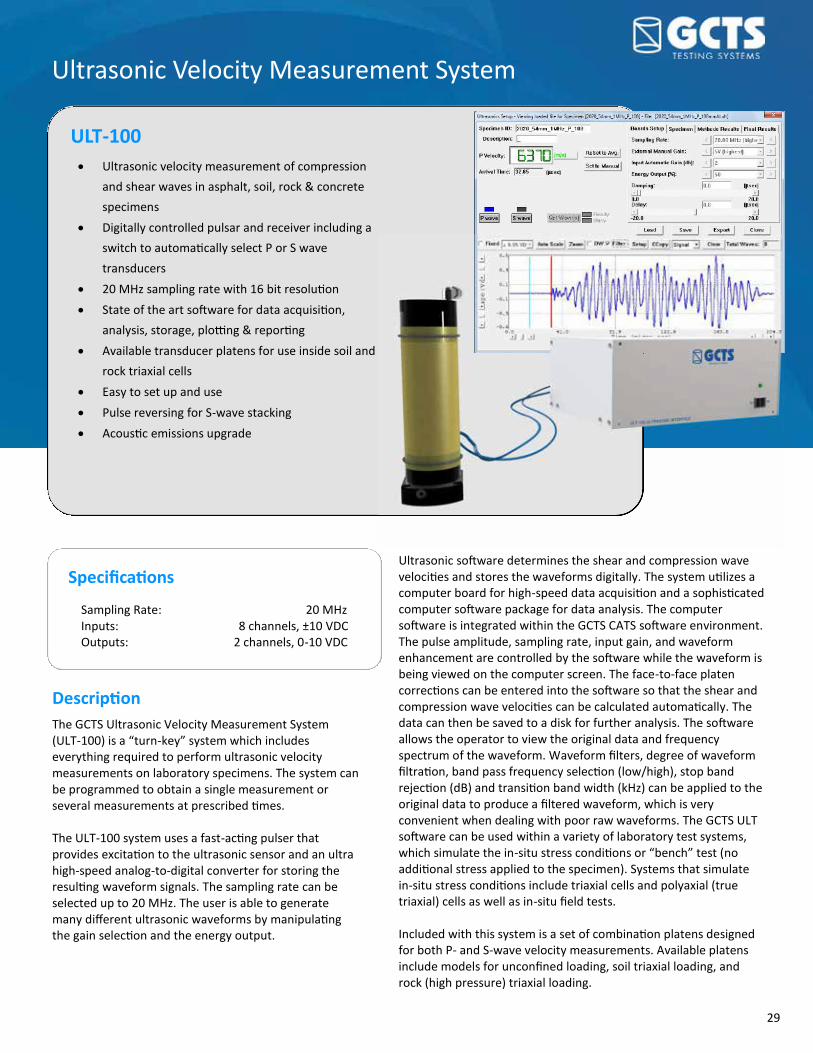
29
Ultrasonic Velocity Measurement System
ULT-100 Ultrasonic velocity measurement of compression
and shear waves in asphalt, soil, rock & concrete
specimens Digitally controlled pulsar and receiver including a
switch to automatically select P or S wave
transducers 20 MHz sampling rate with 16 bit resolution State of the art software for data acquisition,
analysis, storage, plotting & reporting Available transducer platens for use inside soil and
rock triaxial cells Easy to set up and use Pulse reversing for S-wave stacking Acoustic emissions upgrade
Description The GCTS Ultrasonic Velocity Measurement System (ULT-100) is a “turn-key” system which includes everything required to perform ultrasonic velocity measurements on laboratory specimens. The system can be programmed to obtain a single measurement or several measurements at prescribed times. The ULT-100 system uses a fast-acting pulser that provides excitation to the ultrasonic sensor and an ultra high-speed analog-to-digital converter for storing the resulting waveform signals. The sampling rate can be selected up to 20 MHz. The user is able to generate many different ultrasonic waveforms by manipulating the gain selection and the energy output.
Ultrasonic software determines the shear and compression wave velocities and stores the waveforms digitally. The system utilizes a computer board for high-speed data acquisition and a sophisticated computer software package for data analysis. The computer software is integrated within the GCTS CATS software environment. The pulse amplitude, sampling rate, input gain, and waveform enhancement are controlled by the software while the waveform is being viewed on the computer screen. The face-to-face platen corrections can be entered into the software so that the shear and compression wave velocities can be calculated automatically. The data can then be saved to a disk for further analysis. The software allows the operator to view the original data and frequency spectrum of the waveform. Waveform filters, degree of waveform filtration, band pass frequency selection (low/high), stop band rejection (dB) and transition band width (kHz) can be applied to the original data to produce a filtered waveform, which is very convenient when dealing with poor raw waveforms. The GCTS ULT software can be used within a variety of laboratory test systems, which simulate the in-situ stress conditions or “bench” test (no additional stress applied to the specimen). Systems that simulate in-situ stress conditions include triaxial cells and polyaxial (true triaxial) cells as well as in-situ field tests. Included with this system is a set of combination platens designed for both P- and S-wave velocity measurements. Available platens include models for unconfined loading, soil triaxial loading, and rock (high pressure) triaxial loading.
Specifications
Sampling Rate: 20 MHz Inputs: 8 channels, ±10 VDC Outputs: 2 channels, 0-10 VDC
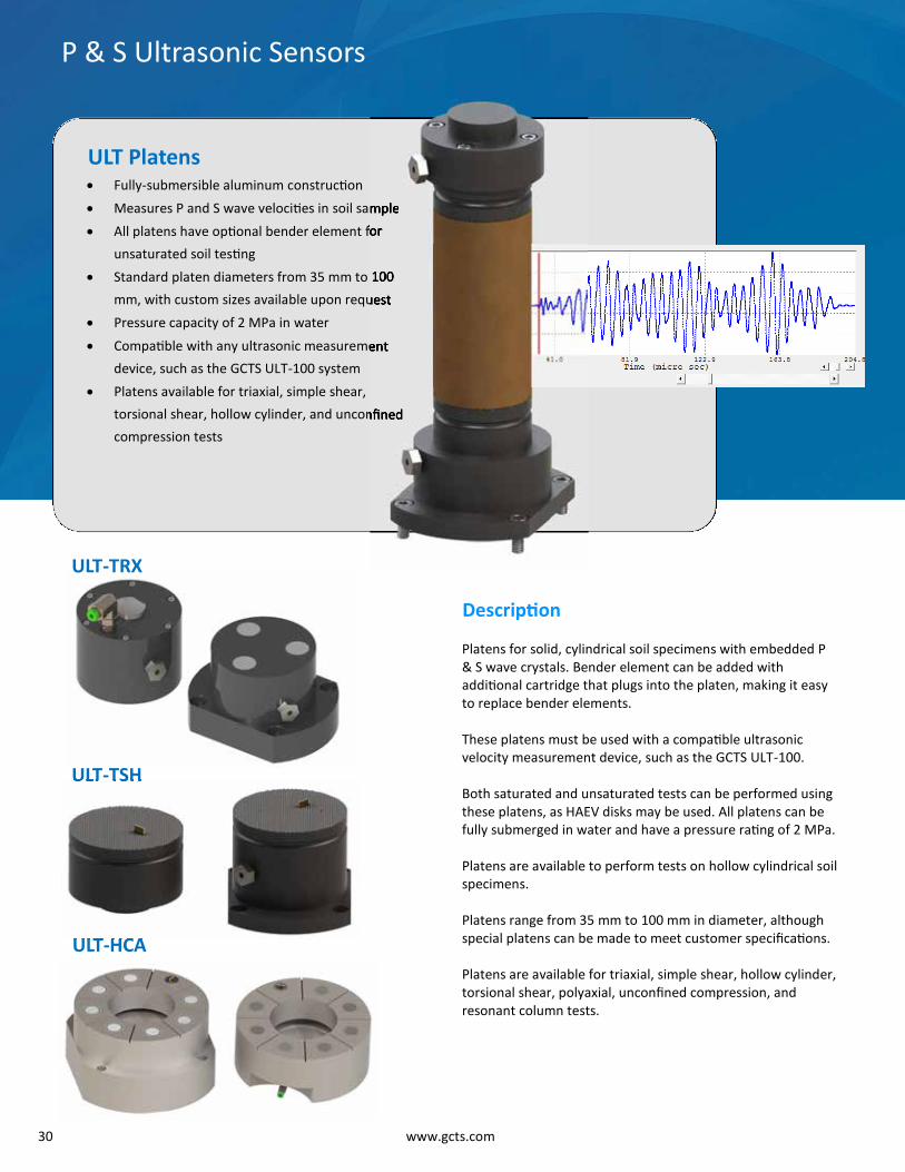
30 www.gcts.com
P & S Ultrasonic Sensors
ULT-TRX
ULT Platens
ULT-TSH
Description
Platens for solid, cylindrical soil specimens with embedded P & S wave crystals. Bender element can be added with additional cartridge that plugs into the platen, making it easy to replace bender elements. These platens must be used with a compatible ultrasonic velocity measurement device, such as the GCTS ULT-100. Both saturated and unsaturated tests can be performed using these platens, as HAEV disks may be used. All platens can be fully submerged in water and have a pressure rating of 2 MPa. Platens are available to perform tests on hollow cylindrical soil specimens. Platens range from 35 mm to 100 mm in diameter, although special platens can be made to meet customer specifications. Platens are available for triaxial, simple shear, hollow cylinder, torsional shear, polyaxial, unconfined compression, and resonant column tests.
ULT-HCA
Fully-submersible aluminum construction Measures P and S wave velocities in soil sample All platens have optional bender element for
unsaturated soil testing Standard platen diameters from 35 mm to 100
mm, with custom sizes available upon request Pressure capacity of 2 MPa in water Compatible with any ultrasonic measurement
device, such as the GCTS ULT-100 system Platens available for triaxial, simple shear,
torsional shear, hollow cylinder, and unconfined
compression tests
ULT TSH
ULT HCA
Measures P and S wave velocities in soil sample
All platens have optional bender element for
Standard platen diameters from 35 mm to 100
mm, with custom sizes available upon request
Compatible with any ultrasonic measurement
torsional shear, hollow cylinder, and unconfined

31
The GCTS LVDT Calibration Device provides a very simple and
easy-to-use technique to accurately calibrate a wide variety of
LVDTs. The DCD-25 features spring loaded linear displacement
to prevent system compliance when reversing directions. The
readout is available in both SI and English units. The device has
an adjustable mounting bracket that can accommodate LVDTs
of most sizes. It provides a calibration range of 25 mm (1 inch)
with 0.001 mm (0.00005 inch) resolution.
DCD-25 LVDT Calibration Device
GCTS Soil Testing Accessories
ACC-CM Specimen Compaction Mold
ACC-CM Compaction split mold/jacket stretcher for
cylindrical specimens with a height of 2.0 times the diameter. Anodized aluminum construction with vacuum port and precision machined spiral grooving for
even membrane expansion. Split compaction molds are
available for up to 300 mm diameter specimens.
TRXM Specimen Latex Membranes
Impermeable latex membranes for up to 300 mm (12
in.) diameter specimens. The length of the membranes
is sufficient to accommodate tall specimens up to 2.5
times the diameter with overlap for the top and bottom
loading platens for O-ring sealing. Membranes are available in 0.3 mm or 0.6 mm thickness (for diameters
above 150 mm, membranes are 2 mm thick).
Membranes come in pack of one dozen (12).

32 www.gcts.com
The GCTS Diffused Air Flushing Device is an accessory designed
to eliminate diffused air bubbles formed beneath ceramic plates
during unsaturated soil testing. The GCTS Diffused-Air Flushing
device is connected to the bottom of the ceramic stone via a
computer-controlled ball valve. A water level sensor is attached
to the bottom of the device. Air flushing is performed by
opening the ball valve and moving a sufficient amount of water.
Then the water level is brought back to the original level by the
pressure/volume controller.
DAF-200 Diffused Air Flushing Device
Installation & Training
GCTS has highly knowledgeable and professional staff who are
capable of training your system operators regardless of the
operator’s level of familiarity with the systems. Our training staff has decades of experience ranging from
commercial to high-level research. They will guide your
operators step-by-step to ensure they are fully comfortable
with the entire testing process. Our team is also available to
help with system installation and maintenance. Short courses
are also periodically offered at GCTS facilities. Please contact
GCTS to schedule an appointment.
GCTS Soil Testing Accessories
VCD-400 Volume Change Device The GCTS Volume Change Device (VCD-400) is equipped with a frictionless rolling diaphragm and an internal LVDT guided by a ball bearing, which enables volume change measurements with no pressure differential. Resolution 0.01 cc Stroke volume capacity 400 cc Pressure capacity 2,000 kPa Excitation 5 VAC @ 3 kHz Output 2.6 V/V (approximately) Automatic 4-way directional valve control 24 VDC Operation VCD-400A—Automatic VCD-400M—Manual

Product Overview Asphalt Testing Systems ....................................................................................... 4 Asphalt Mixture Performance Tester (AMPT-15) .................................................................................... 4 Asphalt Pavement Tester (APT-100E) ...................................................................................................... 5 Asphalt Testing Machine (ATM-025/100) ................................................................................................ 6 Advanced Dynamic Modulus Testing System (ADM-100) ....................................................................... 8 Beam Flexural Fatigue Testing System (BFF-5) ........................................................................................ 9 Superpave Gyratory Compactor (GRC-10) ............................................................................................. 10 Servo-Controlled Gyratory Compactor (GRC-20)................................................................................... 11 Hamburg Wheel-Tracking Tester (HWTT-100) ...................................................................................... 12 Resilient Modulus Testing System (MRT-050/100/200/300) ................................................................ 13 Asphalt Testing Components ............................................................................. 14 Asphalt Coring Device (ACD-150) ........................................................................................................... 14 Specimen Grinder (RSG-200) ................................................................................................................. 14 Automatic Positioning Fixture (GPF-100) .............................................................................................. 14 Specimen Lab Saws (RLS-100/200) ........................................................................................................ 15 Specimen Flatness Gage (RFG-100) ....................................................................................................... 15 LVDT Calibration Device (DCD-25) ......................................................................................................... 16 Calibration Specimens (CAL-100) ........................................................................................................... 16 Direct Tension Jig for Asphalt (DTA-100) ............................................................................................... 17 Environmental Chamber (ECH-30) ......................................................................................................... 17 Software & Electronics ........................................................................................ 17 Digital Signal Conditioning and Control Units (SCON-1400/1500/3000)............................................... 17 Advanced Computer-Aided Testing Software (CATS-ADV) .................................................................... 18 Application Software Modules ............................................................................................................... 19 Application for iPhone and iPad (gTest) ................................................................................................ 21
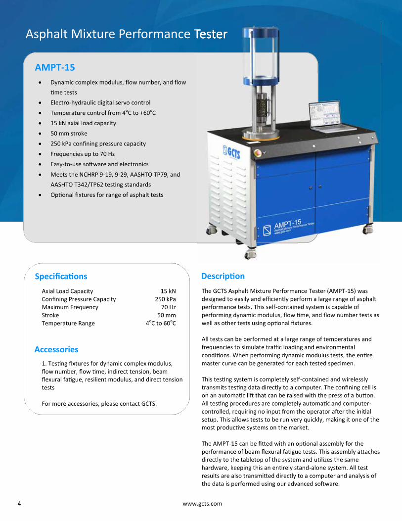
4 www.gcts.com
AMPT-15
Asphalt Mixture Performance Tester
Dynamic complex modulus, flow number, and flow
time tests Electro-hydraulic digital servo control Temperature control from 4oC to +60oC 15 kN axial load capacity 50 mm stroke 250 kPa confining pressure capacity Frequencies up to 70 Hz Easy-to-use software and electronics Meets the NCHRP 9-19, 9-29, AASHTO TP79, and
AASHTO T342/TP62 testing standards Optional fixtures for range of asphalt tests
Specifications Axial Load Capacity 15 kN Confining Pressure Capacity 250 kPa Maximum Frequency 70 Hz Stroke 50 mm Temperature Range 4oC to 60oC
Accessories 1. Testing fixtures for dynamic complex modulus, flow number, flow time, indirect tension, beam flexural fatigue, resilient modulus, and direct tension tests For more accessories, please contact GCTS.
The GCTS Asphalt Mixture Performance Tester (AMPT-15) was designed to easily and efficiently perform a large range of asphalt performance tests. This self-contained system is capable of performing dynamic modulus, flow time, and flow number tests as well as other tests using optional fixtures. All tests can be performed at a large range of temperatures and frequencies to simulate traffic loading and environmental conditions. When performing dynamic modulus tests, the entire master curve can be generated for each tested specimen. This testing system is completely self-contained and wirelessly transmits testing data directly to a computer. The confining cell is on an automatic lift that can be raised with the press of a button. All testing procedures are completely automatic and computer-controlled, requiring no input from the operator after the initial setup. This allows tests to be run very quickly, making it one of the most productive systems on the market. The AMPT-15 can be fitted with an optional assembly for the performance of beam flexural fatigue tests. This assembly attaches directly to the tabletop of the system and utilizes the same hardware, keeping this an entirely stand-alone system. All test results are also transmitted directly to a computer and analysis of the data is performed using our advanced software.
Description
Asphalt Mixture Performance Tester

5
APT-100E
Asphalt Pavement Tester
Economical solution for advanced asphalt
pavement testing Dynamic complex modulus, flow number, flow
time, indirect tension, beam flexural fatigue,
resilient modulus, and direct tension tests all
possible using this system Precise, accurate, quiet, and compact Frequencies up to 70 Hz Temperature control from –10oC to +60oC Complete “turn-key” system Meets most recent AASHTO, ASTM, and
European testing standards
Specifications Static Load Capacity 100 kN Dynamic Load Capacity 85 kN Maximum Frequency 70 Hz Vertical Daylight Opening 1000 mm Horizontal Daylight Opening 400 m Temperature Range -10oC to 60oC
Accessories 1. Testing fixtures for dynamic complex modulus, flow number, flow time, indirect tension, beam flexural fatigue, resilient modulus, and direct tension tests For more accessories, please contact GCTS.
The GCTS Asphalt Pavement Tester (APT-100E) is the most affordable testing system on the market that offers a complete assortment of dynamic testing procedures for asphalt concrete. All equipment is offered in a modular fashion, so the user can select only the required testing modes. All necessary components, including an environmental chamber, A/C compressor, hydraulic pump, and electronics, are integrated into the single system. Fixtures are available to allow the APT-100E to perform dynamic modulus, resilient modulus, beam fatigue, direct tension, indirect tension, flow number, and flow time tests. Advanced software and electronics create completely “turn-key” system for each test, as all testing procedures are computer-controlled. The APT-100E includes a specially designed dynamic actuator for frequencies up to 70 Hz with minimal friction for improved accuracy. The included environmental chamber has a large front viewing window, allowing for visual evaluation during testing. This chamber has temperature control better than 0.2oC.
Description
Economical solution for advanced asphalt
Dynamic complex modulus, flow number, flow
time, indirect tension, beam flexural fatigue,
resilient modulus, and direct tension tests all
C

6 www.gcts.com
Advanced testing for Hot Mix Asphalt (HMA) and
unbound materials Dynamic complex modulus, flow number, flow time,
indirect tension, beam flexural fatigue, and resilient
modulus tests Electro-Hydraulic Digital Servo Control Frequencies up to 70 Hz Modular design with easy to use software and
electronics Meets the newest AASHTO (Superpave), ASTM and
European (EN-12697-24,25,26) standards Complete “turn-key” system
ATM-025/100
Servo-Hydraulic Asphalt Testing Machine
Description
high frequency dynamic tests. The GCTS controller has several adaptive compensation techniques to improve the control precision without user intervention. Adaptive control allows the system to precisely match the desired cyclic stress amplitudes throughout the tests. The ATM 025/100 includes a sliding drawer to easily remove and install test specimens minimizing the time the environmental door is open. GCTS offers platens for unconfined dynamic modulus, triaxial cells for testing 100 mm (4 inch) diameter specimens cored out of a 150 mm (6 inch) specimens, indirect tension and beam flexural fatigue fixtures. The above devices comply with the applicable requirements of AASHTO, ASTM and European (EN-12697-24,25,26) specifications for testing bituminous mixtures.
Specifications Dynamic Load Capacity 25 kN / 100 kN Stroke 100 mm / 100 mm Vertical Opening 1200 mm / 1200 mm Horizontal Opening 600 mm / 600 mm Temperature Range -18oC to 80oC
The GCTS ATM-025/100 is a modular testing system that can be configured to test asphalt in a variety of modes. The system includes an environmental chamber which houses the optional accessories required to perform dynamic complex modulus, flow number, flow time, indirect tension, beam flexural fatigue, and resilient modulus tests. The fully Integrated Digital Servo Controller has an embedded microprocessor capable of performing all test functions even if the Windows computer is turned off. It provides automatic dynamic control mode switching between any connected transducer or calculated parameter. This controller also conditions all transducers used in the ATM-025/100 system. The universal input boards also include digital gain control for automatic range setting. This digital controller is capable of updating the control loop at up to 6 kHz as is required for
ATM-025/100
Hydraulic Asphalt Testing Machine
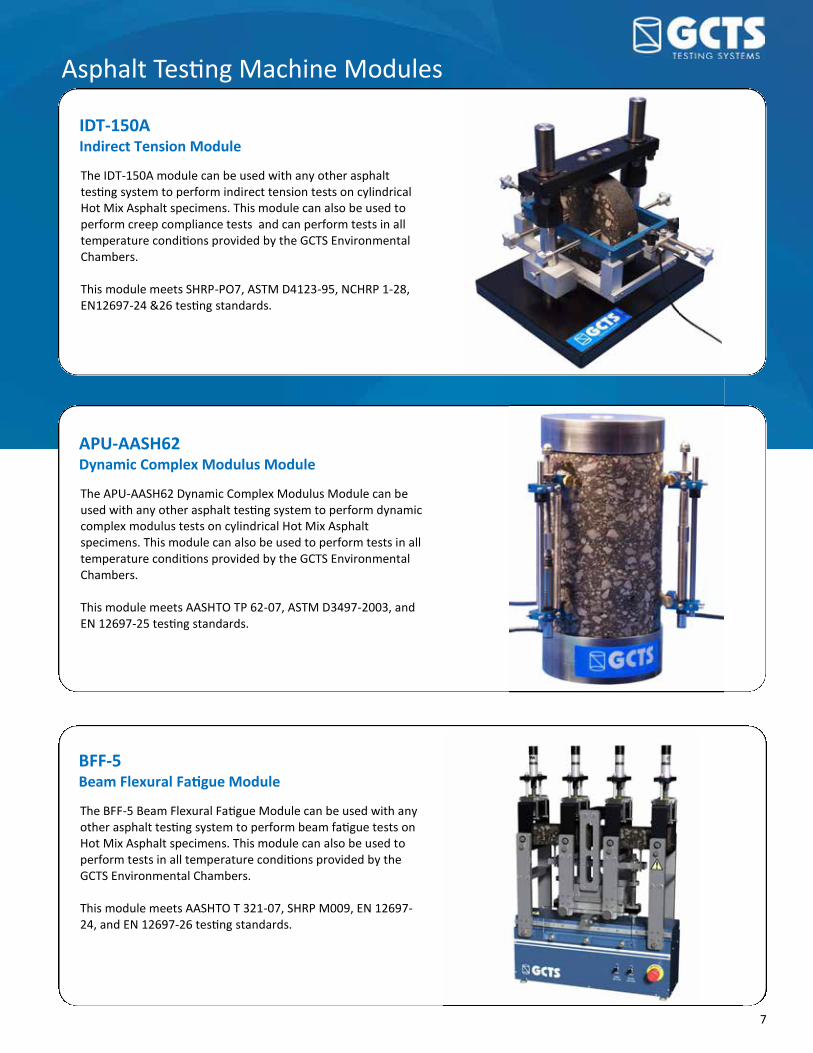
7
The IDT-150A module can be used with any other asphalt testing system to perform indirect tension tests on cylindrical Hot Mix Asphalt specimens. This module can also be used to perform creep compliance tests and can perform tests in all temperature conditions provided by the GCTS Environmental Chambers. This module meets SHRP-PO7, ASTM D4123-95, NCHRP 1-28, EN12697-24 &26 testing standards.
IDT-150A Indirect Tension Module
The APU-AASH62 Dynamic Complex Modulus Module can be used with any other asphalt testing system to perform dynamic complex modulus tests on cylindrical Hot Mix Asphalt specimens. This module can also be used to perform tests in all temperature conditions provided by the GCTS Environmental Chambers. This module meets AASHTO TP 62-07, ASTM D3497-2003, and EN 12697-25 testing standards.
APU-AASH62 Dynamic Complex Modulus Module
The BFF-5 Beam Flexural Fatigue Module can be used with any other asphalt testing system to perform beam fatigue tests on Hot Mix Asphalt specimens. This module can also be used to perform tests in all temperature conditions provided by the GCTS Environmental Chambers. This module meets AASHTO T 321-07, SHRP M009, EN 12697-24, and EN 12697-26 testing standards.
BFF-5 Beam Flexural Fatigue Module
Asphalt Testing Machine Modules

8 www.gcts.com
Specifications
ADM-100
Automated Dynamic Modulus Testing System
Description
Specifications Dynamic Load Capacity 25 kN Static Load Capacity 100 kN Stroke 100 mm Vertical Opening 1200 mm Horizontal Opening 600 mm Temperature Range -15oC to 80o-C Deformation Sensor 30 mm range 0.5 micron repeatability
The GCTS Automatic Dynamic Modulus Testing System (ADM-100) was designed to dramatically increase the productivity of asphalt testing laboratories. This machine allows a full master curve to be developed for up to six specimens at once without any input from the operator after the initial setup. This machine includes a rotating table that can fit up to six specimens. During the test, each specimen will rotate into position below the loading piston, so the operator does not need to open the door to the environmental chamber and reposition the specimen. This eliminates the
Completely automatic dynamic modulus system Reduced testing costs Obtain full Master Curve on up to six specimens
without user intervention Fast and easy specimen loading Electro-hydraulic digital servo control Frequencies up to 80 Hz Temperature control from –15oC to 80oC Capable of performing other tests, such as direct
and indirect tension, beam fatigue, and more
time needed to stabilize the temperature after the door has opened and allows the test to be performed while the operator is away, allowing the complete test to be performed in less than three days rather the traditional week. All deformation measurements are made using two optical micrometers. These sensors can measure deformations using any axial gage length and can account for any permanent deformations experienced by the specimen during testing. By using these sensors, the specimens can be rotated into position for testing and can be set up for measurements without needing to open the environmental chamber door. Since the door does not need to be opened during testing, the operator does not need to wait for the temperature in the chamber to equilibrate between tests at the same temperature. In addition, tests can be run without the operator present, allowing tests to run overnight.
Automated Dynamic Modulus Testing System

9
Advanced testing for Hot Mix Asphalt (HMA) to
determine the pavement fatigue life Stand-alone apparatus with a compact design,
does not require a Universal Testing Machine Electro-pneumatic or electro-hydraulic digital
servo control Frequencies up to 60 Hz Complete “turn-key” system Meets the newest SHRP, AASHTO (Superpave),
ASTM and European (EN-12697-24,26)
standards
Specifications
BFFA-5
Beam Flexural Fatigue Testing System
Description
is recommended for thinner pavement layers (<5” thickness); while in thicker pavements (>5” thickness) constant stress loading simulates the field conditions more closely. The BFFA-5 can perform the fatigue test in both modes at frequencies up to 60 Hertz. The BFFA-5 stand-alone apparatus is a self-contained system featuring cradle support for the asphalt beam, clamps with controlled clamping force, LVDT, load cell and servo-controlled pneumatic or hydraulic actuators. The BFFA-5 is controlled with a GCTS Signal Conditioning and Control Unit (SCON Unit) which is interfaced with WindowsTM Computer Aided Testing Software (CATS). The software automatically obtains the fatigue life parameters such as: initial stiffness, maximum tensile stress/strain, phase angle, dissipated energy per cycle, flexural stiffness, and number of repetitions to failure. The system also supports the GCTS ECH-30CS Environmental Chamber as an optional attachment. This chamber is capable of controlling the specimen temperature throughout the test. The environmental chamber control accuracy is better than ± 0.5oC. Temperatures of –15oC to +80oC (-30oC with liquid Nitrogen boost) can be achieved with this option.
Specifications Dynamic Load Capacity 5 kN (10 kN optional) Stroke 5 mm Deformation Sensor ±1 mm range
0.5 micron repeatability Temperature Range -4oC to 60oC
Accessories
1. Synthetic Beam Specimens 2. 4-Point Beam Fatigue CATS software For more accessories, please contact GCTS.
The GCTS Stand-Alone Beam Flexural Fatigue Apparatus (BFFA-5) is an advanced Hot Mix Asphalt (HMA) testing system used to determine the fatigue life of the pavement layer. The fatigue life is an important indicator of the field performance of the asphalt subject to repeated flexural loading. The fatigue test on the asphalt beam can be conducted in two modes: constant strain/deflection or constant stress/load; both utilizing haversine, sine, square, triangular, or user-defined. The constant strain mode
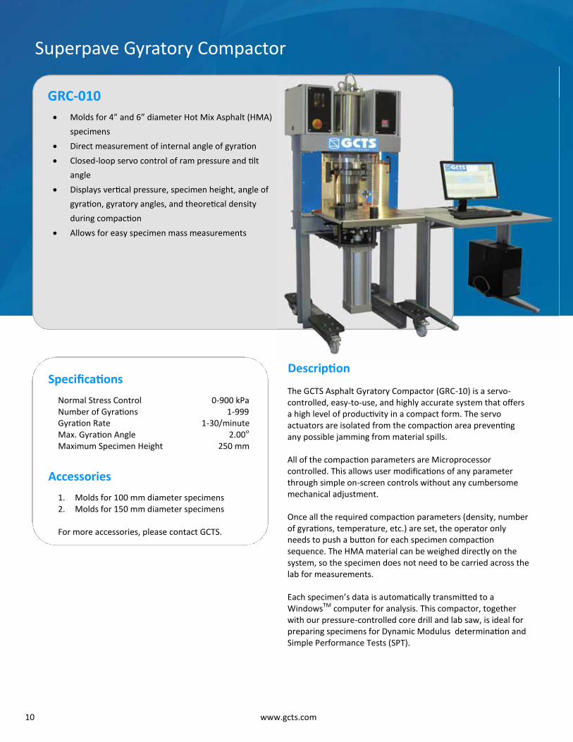
10 www.gcts.com
Molds for 4” and 6” diameter Hot Mix Asphalt (HMA)
specimens Direct measurement of internal angle of gyration Closed-loop servo control of ram pressure and tilt
angle Displays vertical pressure, specimen height, angle of
gyration, gyratory angles, and theoretical density
during compaction Allows for easy specimen mass measurements
GRC-010
Superpave Gyratory Compactor
Description
The GCTS Asphalt Gyratory Compactor (GRC-10) is a servo-controlled, easy-to-use, and highly accurate system that offers a high level of productivity in a compact form. The servo actuators are isolated from the compaction area preventing any possible jamming from material spills. All of the compaction parameters are Microprocessor controlled. This allows user modifications of any parameter through simple on-screen controls without any cumbersome mechanical adjustment. Once all the required compaction parameters (density, number of gyrations, temperature, etc.) are set, the operator only needs to push a button for each specimen compaction sequence. The HMA material can be weighed directly on the system, so the specimen does not need to be carried across the lab for measurements. Each specimen’s data is automatically transmitted to a WindowsTM computer for analysis. This compactor, together with our pressure-controlled core drill and lab saw, is ideal for preparing specimens for Dynamic Modulus determination and Simple Performance Tests (SPT).
Specifications Normal Stress Control 0-900 kPa Number of Gyrations 1-999 Gyration Rate 1-30/minute Max. Gyration Angle 2.00o Maximum Specimen Height 250 mm
Accessories 1. Molds for 100 mm diameter specimens 2. Molds for 150 mm diameter specimens For more accessories, please contact GCTS.

11
Self-heating molds for 4” and 6” diameter Hot Mix
Asphalt (HMA) specimens Continuous positive feedback to maintain gyration
angle precision throughout compaction Closed-loop servo control of ram pressure and tilt
angle Automatic material mass measurements High stiffness / low compliance frame Measures shear stresses Meets AASHTO 312-04 (Preparing and Determining
the Density of Hot Mix Asphalt (HMA) by means of
Superpave Gyratory Compactor)
GRC-020
Servo-Controlled Gyratory Compactor
Description
parameter through simple on-screen controls without any cumbersome mechanical adjustment. The self-heating molds eliminate the handling of heavy and hot components for each compacted specimen. The mold temperature is precisely controlled allowing the user to specify the temperature during compaction. The controlled temperature can be prescribed to be constant or variable as a function of time during compaction. Because the mold is rigidly fastened and self-heated, it not only provides a high level of reliability, but eliminates the need to purchase multiple expensive molds and large ovens to keep them at the required temperature. GCTS offers molds for compacting 100 and 150 mm (4 and 6 inches) diameter specimens with heights of up to 200 mm (8 inches). Once all the required compaction parameters (density, number of gyrations, temperature, etc.) are set, the operator only needs to push a button for each specimen compaction sequence. The HMA material is weighed automatically and its mass entered into the controller automatically virtually eliminating operator data entry errors. The GCTS GRC-20 is also capable of measuring the shear stress required for compaction. Each specimen’s data is automatically recorded in the GRC-20 memory for printing or transferring to a Windows computer or network at any time. This compactor, together with our pressure-controlled core drill and lab saw, is ideal for preparing specimens for Dynamic Modulus determination and Simple Performance Tests (SPT).
Specifications Normal Load Control 0-18 kN Normal Stress Control 0-1000 kPa Number of Gyrations 1-9999 Gyration Rate 1-60/minute Gyration Angle 0.02-3.00o (±0.02o) Maximum Specimen Height 200 mm
Accessories 1. Molds for 100 mm diameter specimens 2. Molds for 150 mm diameter specimens For more accessories, please contact GCTS.
The GCTS Gyratory Compactor offers a high level of accuracy while remaining easy to use. The GRC-20 is a fully automated servo-controlled compactor that provides a high productivity rate. The servo-controlled mechanism provides a high level of accuracy for the tilt angle as well as the gyration rate and start/stop position. The servo actuators are isolated from the compaction area preventing any possible jamming from material spills. All of the compaction parameters are Microprocessor controlled. This allows user modifications of any
heating molds for 4” and 6” diameter Hot Mix
Continuous positive feedback to maintain gyration
loop servo control of ram pressure and tilt
04 (Preparing and Determining
the Density of Hot Mix Asphalt (HMA) by means of
Controlled Gyratory Compactor
parameter through simple on-screen controls without any cumbersome mechanical adjustment.
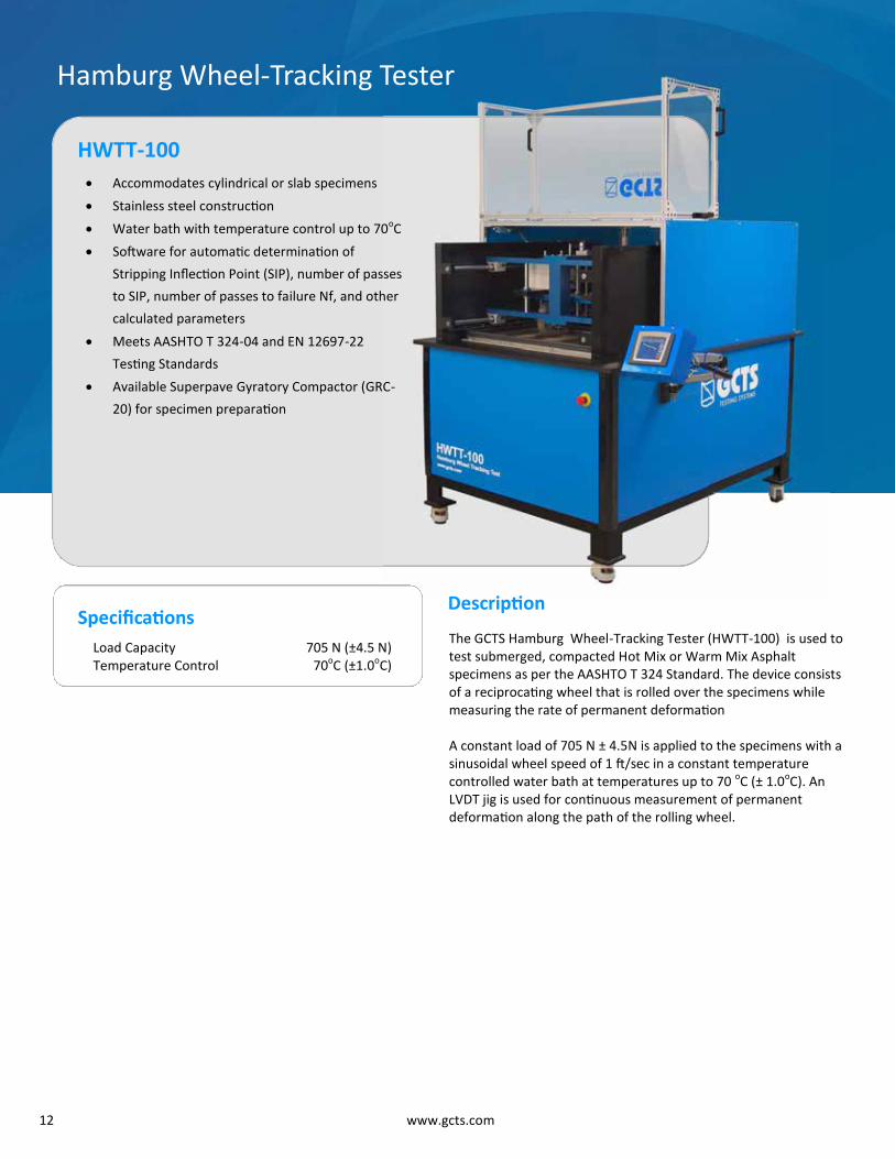
12 www.gcts.com
Accommodates cylindrical or slab specimens Stainless steel construction Water bath with temperature control up to 70oC Software for automatic determination of
Stripping Inflection Point (SIP), number of passes
to SIP, number of passes to failure Nf, and other
calculated parameters Meets AASHTO T 324-04 and EN 12697-22
Testing Standards Available Superpave Gyratory Compactor (GRC-
20) for specimen preparation
HWTT-100
Hamburg Wheel-Tracking Tester
Specifications Load Capacity 705 N (±4.5 N) Temperature Control 70oC (±1.0oC)
The GCTS Hamburg Wheel-Tracking Tester (HWTT-100) is used to test submerged, compacted Hot Mix or Warm Mix Asphalt specimens as per the AASHTO T 324 Standard. The device consists of a reciprocating wheel that is rolled over the specimens while measuring the rate of permanent deformation A constant load of 705 N ± 4.5N is applied to the specimens with a sinusoidal wheel speed of 1 ft/sec in a constant temperature controlled water bath at temperatures up to 70 oC (± 1.0oC). An LVDT jig is used for continuous measurement of permanent deformation along the path of the rolling wheel.
Description
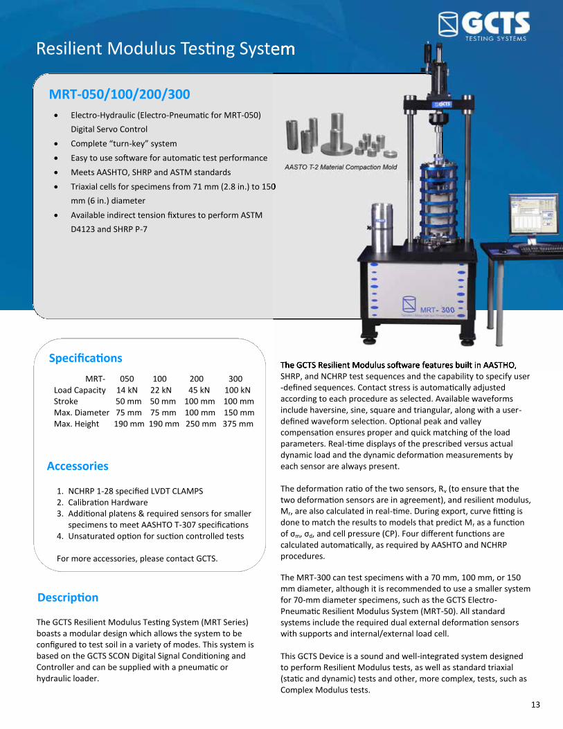
13
Resilient Modulus Testing System
MRT-050/100/200/300 Electro-Hydraulic (Electro-Pneumatic for MRT-050)
Digital Servo Control Complete “turn-key” system Easy to use software for automatic test performance Meets AASHTO, SHRP and ASTM standards Triaxial cells for specimens from 71 mm (2.8 in.) to 150
mm (6 in.) diameter Available indirect tension fixtures to perform ASTM
D4123 and SHRP P-7
Specifications MRT- 050 100 200 300 Load Capacity 14 kN 22 kN 45 kN 100 kN Stroke 50 mm 50 mm 100 mm 100 mm Max. Diameter 75 mm 75 mm 100 mm 150 mm
Max. Height 190 mm 190 mm 250 mm 375 mm
Accessories
1. NCHRP 1-28 specified LVDT CLAMPS 2. Calibration Hardware 3. Additional platens & required sensors for smaller
specimens to meet AASHTO T-307 specifications 4. Unsaturated option for suction controlled tests For more accessories, please contact GCTS.
Description
The GCTS Resilient Modulus software features built in AASTHO, SHRP, and NCHRP test sequences and the capability to specify user-defined sequences. Contact stress is automatically adjusted according to each procedure as selected. Available waveforms include haversine, sine, square and triangular, along with a user-defined waveform selection. Optional peak and valley compensation ensures proper and quick matching of the load parameters. Real-time displays of the prescribed versus actual dynamic load and the dynamic deformation measurements by each sensor are always present. The deformation ratio of the two sensors, Rv (to ensure that the two deformation sensors are in agreement), and resilient modulus, Mr, are also calculated in real-time. During export, curve fitting is done to match the results to models that predict Mr as a function of σm, σd, and cell pressure (CP). Four different functions are calculated automatically, as required by AASHTO and NCHRP procedures. The MRT-300 can test specimens with a 70 mm, 100 mm, or 150 mm diameter, although it is recommended to use a smaller system for 70-mm diameter specimens, such as the GCTS Electro-Pneumatic Resilient Modulus System (MRT-50). All standard systems include the required dual external deformation sensors with supports and internal/external load cell. This GCTS Device is a sound and well-integrated system designed to perform Resilient Modulus tests, as well as standard triaxial (static and dynamic) tests and other, more complex, tests, such as Complex Modulus tests.
The GCTS Resilient Modulus Testing System (MRT Series) boasts a modular design which allows the system to be configured to test soil in a variety of modes. This system is based on the GCTS SCON Digital Signal Conditioning and Controller and can be supplied with a pneumatic or hydraulic loader.
Resilient Modulus Testing System
Triaxial cells for specimens from 71 mm (2.8 in.) to 150
The GCTS Resilient Modulus software features built in AASTHO,

14 www.gcts.com
GCTS Asphalt Testing Accessories
The GCTS ACD-150 allows for either force or stroke control,
which optimizes feeding rates during coring. This allows for
precise specimens to be made, even if the material is not
homogeneous. Diamond coring barrels are available for
different specimen types, diameters, and lengths. 150 to 4200 rpm spindle speeds 1.5 HP motor Automatic down feed mechanism with 250 mm travel Stiff frame to eliminate specimen ridges Drilling rate controlled by pressure and speed
ACD-150 Pressure-Controlled Coring Machine
RSG-200 Specimen Grinder
The GCTS RSG-200 provides the final step to prepare test
specimens with parallel and flat ends, according to ASTM
and ISRM standards. The grinder is driven by a heavy-duty
2 HP electro motor. A diamond grinding cup wheel is
provided, along with a custom stainless steel sample
holder. GCTS offers sample holders for specimen diameters
from 25 mm to 150 mm. The system has a built-in cooling
circulator that cools the grinding cup wheel when
preparing a specimen.
GPF-100 Automatic Positioning Fixture
The GCTS GPF-100 was designed for easy and accurate extensometer holder positioning on the cylindrical asphalt specimens used in Dynamic Modulus tests. With the GPF-100 and the specially designed extensometer holding pins, the need for labor-intensive effort is eliminated and the preparation time is reduced to a fraction of the time normally required. The pin holder front face includes a recess to avoid squeezing the epoxy out while it is pressed against the sample. These pins, together with the GPF-100 fixture, provide the most accurate method of affixing the axial strain measurement sensors for dynamic testing.
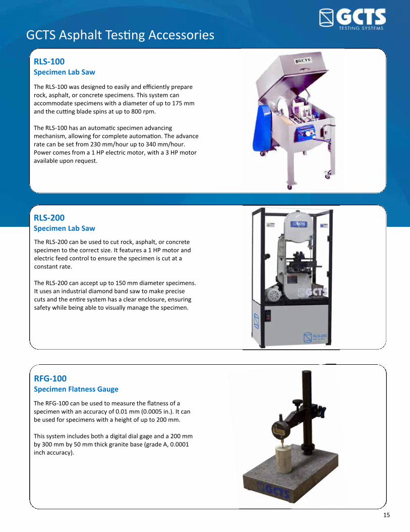
15
GCTS Asphalt Testing Accessories
RLS-200 Specimen Lab Saw
The RLS-200 can be used to cut rock, asphalt, or concrete specimen to the correct size. It features a 1 HP motor and electric feed control to ensure the specimen is cut at a constant rate. The RLS-200 can accept up to 150 mm diameter specimens. It uses an industrial diamond band saw to make precise cuts and the entire system has a clear enclosure, ensuring safety while being able to visually manage the specimen.
The RLS-100 was designed to easily and efficiently prepare rock, asphalt, or concrete specimens. This system can accommodate specimens with a diameter of up to 175 mm and the cutting blade spins at up to 800 rpm. The RLS-100 has an automatic specimen advancing mechanism, allowing for complete automation. The advance rate can be set from 230 mm/hour up to 340 mm/hour. Power comes from a 1 HP electric motor, with a 3 HP motor available upon request.
RLS-100 Specimen Lab Saw
RFG-100 Specimen Flatness Gauge
The RFG-100 can be used to measure the flatness of a specimen with an accuracy of 0.01 mm (0.0005 in.). It can be used for specimens with a height of up to 200 mm. This system includes both a digital dial gage and a 200 mm by 300 mm by 50 mm thick granite base (grade A, 0.0001 inch accuracy).
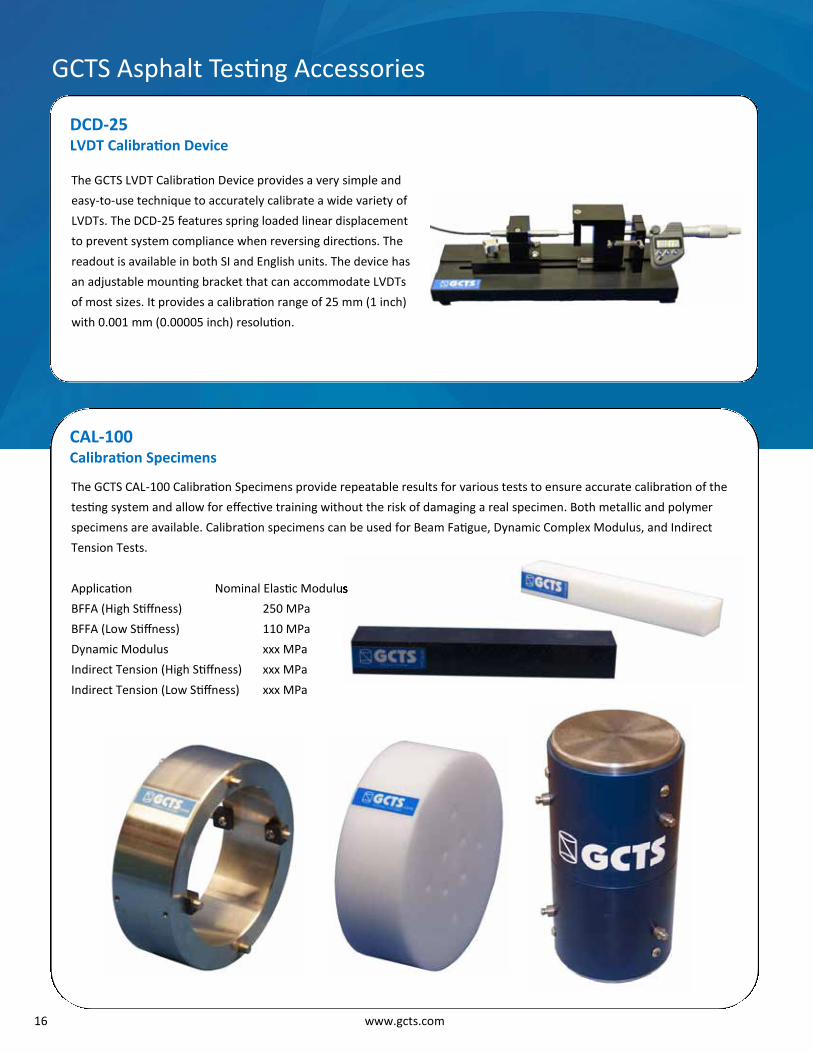
16 www.gcts.com
GCTS Asphalt Testing Accessories
The GCTS LVDT Calibration Device provides a very simple and
easy-to-use technique to accurately calibrate a wide variety of
LVDTs. The DCD-25 features spring loaded linear displacement
to prevent system compliance when reversing directions. The
readout is available in both SI and English units. The device has
an adjustable mounting bracket that can accommodate LVDTs
of most sizes. It provides a calibration range of 25 mm (1 inch)
with 0.001 mm (0.00005 inch) resolution.
DCD-25 LVDT Calibration Device
The GCTS CAL-100 Calibration Specimens provide repeatable results for various tests to ensure accurate calibration of the
testing system and allow for effective training without the risk of damaging a real specimen. Both metallic and polymer
specimens are available. Calibration specimens can be used for Beam Fatigue, Dynamic Complex Modulus, and Indirect
Tension Tests. Application Nominal Elastic Modulus BFFA (High Stiffness) 250 MPa BFFA (Low Stiffness) 110 MPa Dynamic Modulus xxx MPa Indirect Tension (High Stiffness) xxx MPa Indirect Tension (Low Stiffness) xxx MPa
CAL-100 Calibration Specimens
Nominal Elastic Modulus

17
ECH-30CS/CH Environmental Chambers
The GCTS Environmental Chamber is a temperature control device capable of accommodating the testing fixtures for soil, asphalt, rock, and other construction materials while maintaining the temperature of the specimen with an accuracy of 0.5oC. The chamber has a full size window in the front for visual monitoring of testing procedures. GCTS offers two Environmental Chambers. The ECH-30CS offers temperature control from –30oC to +80oC and the ECH-30CH offers temperature control from –30oC to +150oC. Both models require liquid nitrogen for cooling. GCTS offers other options to cool to –15oC without liquid nitrogen.
GCTS Asphalt Testing Accessories
Installation & Training
GCTS has highly knowledgeable and professional staff who are
capable of training your system operators regardless of the
operator’s level of familiarity with the systems. Our training staff has decades of experience ranging from
commercial to high-level research. They will guide your
operators step-by-step to ensure they are fully comfortable
with the entire testing process. Our team is also available to
help with system installation and maintenance. Short courses
are also periodically offered at GCTS facilities. Please contact
GCTS to schedule an appointment.
The GCTS Direct Tension Jig for Asphalt (DTA-100) includes a
set of upper and lower crossheads with angle brackets
designed to test asphalt specimens with a diameter of 100
mm. This fixture can be used for direct tension, torsion, and
shear tests on asphalt specimens. An epoxy kit is included to secure asphalt specimens to the
angle brackets. This fixture was designed to be used with the
GCTS ATM-025/100 system.
DTA-100 Direct Tension Jig for Asphalt

33
Digital Signal Conditioning and Control Unit
SCON-1400/1500/3000 24 or 16 bit A/D resolution and 100 kHz conversion rate
with track-and-hold Adaptive digital servo control with Windows™ interface
software Accepts Universal Digital Signal Conditioning modules
for load cells, LVDTs (AC and DC), pressure sensors, or
other analog input signals Internal and external temperature monitoring
Description The GCTS SCON units feature integrated microprocessor-based digital servo controllers and include the GCTS CATS Standard software. They are complete and self-contained modules that feature a built-in function generator, data acquisition, and digital I/O unit. By utilizing state-of-the-art Universal Signal Conditioning boards, these systems can accept load cells, pressure transducers, LVDTs, thermocouples, or other analog input signals. Each channel features digital offset and gain and an anti-alias filter. This system also includes “track-and-hold,” which ensures that the converted values from all attached sensors (load cells, deformation, etc.) represent a single instant in time, eliminating any data skew from delays in the A/D converter. The signal conditioning electronics are fully digital with settings directly manipulated by the software. Different equipment configurations are saved, which makes it very easy to change sensors like load cells or deformation transducers. At the same time, the digital settings are protected from inexperienced users to eliminate accidental modifications to
sensor calibrations and amplifications. In addition, the systems incorporate automatic sensor recognition that will automatically load the correct sensor setup upon connecting or changing a transducer. This system also allows for easy creation of virtual sensors based on existing ones with a smaller calibrated range. Included with these systems is the GCTS CATS Standard Software that is compatible with all versions of Windows™ from XP to the latest operating system. The standard systems also include calculated inputs from one or several analog channels that can be directly servo controlled or monitored in real time. Any system sensor can then be used to provide advanced servo control with "on-the-fly, bump -less" transfer switching between any connected transducer or calculated inputs. The newest SCON system, the SCON-3000, can wirelessly communicate with the controlling computer, allowing a user with a laptop computer to freely move around the laboratory while remaining in control of the testing system.
Specifications SCON-1400 SCON-1500
16 bit 4 AC, 4 DC/SG
4 (max. 2 servo outputs) 800 MHz 4,000 Hz
430 x 380 x 270 mm 90-260 VAC, 50-60 Hz
0.4 kW Wi-Fi, USB, TCP/IP
Resolution Max. Analog Inputs Max. Analog Outputs Micro-Processor Maximum Control Loop Rate Dimensions (WxDxH) Voltage Max. Power Interface
16 bit 8 Universal
4 850 MHz 4,000 Hz
430 x 380 x 270 mm 90-260 VAC, 50-60 Hz
0.4 kW Wi-Fi, USB. TCP/IP
SCON-3000
SCON-3000
24 bit 23 Universal* 23 Universal*
3.4 GHz 10,000 Hz
360 x 305 x 820 mm 90-260 VAC, 50-60 Hz
1.0 kW Wi-Fi, USB, TCP/IP
*Inputs and Outputs are interchangeable. The total number of inputs and outputs must be equal to or less than 23.
Digital Signal Conditioning and Control Unit
24 or 16 bit A/D resolution and 100 kHz conversion rate
Adaptive digital servo control with Windows™ interface
for load cells, LVDTs (AC and DC), pressure sensors, or

34 www.gcts.com
Advanced Computer Aided Testing Software
CATS-ADV Advanced servo control from any system sensor
or calculated variable “On-the-fly, bump-less” transfer and
adaptive compensation Advanced digital temperature control Automatic frequency sweeps Independent and synchronized control of up to
10 outputs Complete units library including SI, metric,
English and user-defined units Real-time graphics of input channels Remote monitoring of test through networks Application programs include Direct Shear,
Triaxial, Hollow Cylinder, Resonant Column, and
more
Description The GCTS Advanced Windows™ compatible software, coupled with SCON electronics, is the most advanced Geotechnical testing software available today. This software has simplified the operation of our instruments, allowing the user to directly program test-calculated parameters in the units of interest based on the specimen dimensions. These parameters are calculated in real-time and are available for display, graph and
control. Since GCTS signal conditioning electronics are fully digital, optimization and calibration settings are software controlled. Alternate equipment configurations can be easily saved within the software so that when a sensor has been changed, the software can quickly recognize the new device and update with new settings. All the offset and gain settings are managed by our computer software, reducing the possibility of
accidentally changing the sensor calibration. The CATS software includes a digital filter on the sensor inputs to help eliminate noise from the digital signal. All of our testing systems have been designed to take full advantage of
our software and electronics so that all test stages can be automatically performed with minimal user intervention. The Universal test module of the CATS Advanced software is a very versatile and powerful module that allows the user to establish any test procedure that they wish. It allows the user to simultaneously control up to 10 outputs (synchronous or asynchronous) in any phase, and allows the user to run unlimited phases or test programs. GCTS offers many application software modules to perform specific test procedures (Triaxial, Direct Shear, Resonant Column, and more), and each module includes the Universal Module to program user-defined tests.
Automatic Mohr circle generation.

32 www.gcts.com
Rock Triaxial Software Module
CATS-TRX-ROCK • Automatic Mohr-Coulomb model fitting
(Mohr circles)
• Complete automatic procedures
• Isotropic and anisotropic consolidation
• Static and dynamic loading with stress/strain
path control including K0 test
• Multi-stage testing
• Modification of stress or strain rates during
testing
• Real time graphics of input channels
• Export data to Excel or other programs
• Easy to setup and conduct triaxial tests
Description
The GCTS TRX-ROCK software is part of the CATS (Computer Aided Testing Software), which coupled with our SCON electronics, is the most advanced geotechnical laboratory testing software available today. This software has simplified the operation of our triaxial instruments allowing the user to directly program test calculated parameters in the units of interest (stress, strain, etc.) based on the specimen dimensions. These parameters are calculated in real time and are available for control, display and/or graph. Example of test calculated parameters include σd—deviator stress, εa—axial strain, εr—radial strain, εv—volumetric strain, Poisson’s ratio, tangent and secant modulus (TRX software modulus contains 20 test inputs). The strain can be calculated from direct deformation inputs, or can be calculated as functions of each other—the option is user selectable. This software includes an automatic procedure for setting the initial ram
contact with the specimen. The ram is first moved in deformation control while monitoring the axial stress. As soon as the ram gets in contact with the specimen, the system automatically switches to axial stress control preventing premature sample failure. This program also calculates the force exerted on the ram by the confining pressure and automatically corrects the axial load required to maintain the deviator stress and thus preventing the ram from lifting while changing the cell pressure. The Static Loading stage is easy to setup and allows the user to perform static loading on the specimen while allowing the user to change the stress and or strain rates for all of the controlled axes (axial, cell pressure and back pressure) during testing. The Dynamic Loading stage allows the user to easily setup a dynamic loading on the specimen. The Universal stage of the TRX software is a very versatile and powerful module that allows the user to establish any custom test procedure that
they wish. It allows the user to simultaneously and independently control the three axes outputs in the test program. The GCTS triaxial testing systems have been designed to take full advantage of our new software and electronics so that all test stages can be automatically performed from beginning to the end with minimal user intervention. For the full specifications regarding the TRX-ROCK software, please see the CATS-TRX-ROCK brochure.

33
Direct Shear Software Module
CATS-DSH • Complete automatic test setup including multi-
stage procedures
• Modification of stress or deformation rates
during testing
• Automatic real time specimen area corrections
• Easy to setup and conduct direct shear tests
• Automatic calculations of friction angle and
cohesion intercept for peak and residual values
• Compatible with most soil & rock direct shear
test systems
Description
The new GCTS DSH software is part of the CATS (Computer Aided Testing Software), which coupled with our new SCON electronics, is the most advanced geotechnical software available today. This software has simplified the operation of direct shear systems allowing the user to directly program test calculated parameters in the units of interest based on the specimen dimensions. These parameters are calculated in real time and are available for display, graph and/or control. The test parameters include σn—normal stress, τ—shear stress, and Ac—corrected area. The software is able to handle cylindrical specimens with circular, rectangular or elliptical cross-sections, and square and rectangular as well as irregular (user defined) specimens while being able to keep track of the specimen area changes automatically. The consolidation stage allows the user to consolidate a specimen. The shear loading stage is easy to setup and allows the user
to perform shear loading on the specimen while allowing the user to change the stress and/or deformation rates for all of the controlled axes (shear and normal axes) during testing. The user can perform normal stiffness controlled test with this stage, either keeping the normal stiffness constant or making it a function. If none of these stages fit the users need, the Universal stage of the DSH module of the CATS software allows the user to establish a custom test procedure. Direct Shear multi-stage test programs can be easily defined and automatically executed. After testing is done, the DSH module allows the user to calculate the friction angle and cohesion intercept for user selected samples. The software calculates and graphs both the peak and residual friction angles and cohesion intercepts. The GCTS Direct Shear testing systems have been designed to take full advantage of our new software and electronics so
that all test stages can be automatically performed from beginning to end with minimal user intervention. To view full specifications regarding DSH software, please see the Direct Shear brochure.

34 www.gcts.com
Point Load Test Software
PntLoad • Automatic test execution, data logging, data analysis,
and test report
• Real time display of test results and statistical results
• Optimized for mass production of rock testing
• Automatic specimen size measurement to increase
productivity and minimize errors
• Compatible with most laptop and desktop PC
computers running Windows™ operating system
Description
The specimens can be tested one after the other, in rapid succession, and the software program will automatically measure the specimen diameter and start/stop the test data logging based upon threshold load values. During the test, there is real time display of the parameters (time, load, deformation) and statistical results from all the previous specimens. The program is capable of deleting data based on comparison with previous data sets and the combined results from the results graph. The GCTS Point Load test system is a convenient test system that has been designed for ease of transportation through its compact, lightweight aluminum construction. Included in the system is a precise digital display to monitor axial load and axial deformation in SI or English units. The system includes an optional easy to use Windows™ software package that interfaces to a laptop or desktop computer.
The software was designed to provide fast, automated testing. The software is able to automatically log test data and statistical data analysis. An option that is available includes Ultrasonic Velocity package (including platens and ultrasonic software). This allows for automatic collection of ultrasonic velocity data. An additional option offered is unconfined compression platens for uniaxial testing.

35
Application Software Modules
CATS-DSH The GCTS Direct Shear Software allows for the complete automation of direct shear tests. This software automatically controls all stages of testing, including consolidation and shearing, and calculates tests parameters in real-time for observation. The user can also easily program custom testing procedures. After testing, the system will automatically calculate the friction angle and cohesion intercept for the sample.
CATS-SSH The GCTS Simple Shear Software is used for automatic performance of simple shear tests. All stages of testing, including saturation, consolidation, and shearing, can be completely computer-controlled, so minimal user intervention is needed during testing. The software is very intuitive and easy to use, which reduces training time and minimizes user error. The results, such as cyclic shear modulus and damping ratio, are automatically calculated and plotted.

36 www.gcts.com
Application Software Modules
CATS-TRX-SOIL
The GCTS Soil Triaxial Software allows for the automatic test execution of soil triaxial tests under static or dynamic loading conditions. This software allows for the automatic control of all test stages, including saturation, consolidation, and shearing. B values are automatically calculated for saturation and consolidation can be performed under both isotropic and anisotropic conditions. Dynamic loading conditions can be used to test for liquefaction, resilient modulus, cyclic strength and more. Multi-stage testing can also be performed using this software. The software will automatically create a Mohr-Coulomb model after testing so results can be analyzed quickly.
CATS-TRX-MRT
The GCTS Resilient Modulus Software automatically performs resilient modulus tests. This software can control all stages of testing, including user-defined, custom stages. The user can also select different waveforms for testing, including sine, haversine, and triangular. During testing, there is on-the-fly measurement of RV (to ensure that the two deformation sensors are in agreement) and Mr. During export, curve fitting is done to fit the results to models that predict Mr as a function of σm, σd, and cell pressure.

37
Application Software Modules
CATS-RC/TSH The GCTS Resonant Column & Torsional Shear Software allows for the automatic test execution of resonant column and torsional shear tests. The software can automatically determine the resonant frequency and damping ratio and automatically plot the hysteresis plot for the shear stress versus shear strain. The shear modulus and damping ratio properties are automatically calculated. The damping ratio is calculated using several methods such as “free vibration decay”, “half power ratio”, and “phase angle”.
CATS-HCA The GCTS Hollow Cylinder Software allows for the automatic performance of hollow cylinder tests. The software completely automates the testing system, allowing it to perform all stages of testing, including saturation, consolidation, and loading with minimal user intervention. The software can compute and control the test with a variety of parameters. This includes the principal stress angle (α), allowing it to easily prescribe the rate and magnitude of the σ1 rotation. The software can be used to conduct dynamic stress/strain path, plane strain simple shear, liquefaction potential, shear modulus and damping ratio tests along with many others.

20 www.gcts.com
Application Software Modules
CATS-IDT
The GCTS Indirect Tension software module allows the user to perform Creep Compliance, Fatigue, Resilient (Stiffness) Modulus, and Tensile Strength tests using an Indirect Tension Apparatus (either American or European standard apparatus). While the user can configure and set up the test to be performed according to a single standard, the software will automatically calculate and display the results for all other available standards.
CATS-BFF
The GCTS Beam Flexural Fatigue software allows for automatic execution and control of a long-term fatigue test with relative ease and flexibility. The fatigue test on the asphalt beam can be conducted in two modes: constant strain/deflection or constant stress/load.

21
Application Software Modules
CATS-TRX-MRT The GCTS Resilient Modulus Software automatically performs resilient modulus tests. This software can control all stages of testing, including user-defined, custom stages. The user can also select different waveforms for testing, including sine, haversine, and triangular. During testing, there is on-the-fly measurement of RV (to ensure that the two deformation sensors are in agreement) and Mr. During export, curve fitting is done to fit the results to models that predict Mr. as a function of σm, σd, and cell pressure.
CATS-DCM
The GCTS Dynamic Complex Modulus software allows for automatic test execution for one or multiple tests. Each individual test can be programmed for different temperatures and frequencies as well as the number of replicates at each temperature and frequency pair. This program includes a function solver to automatically obtain the “master curve” from test data.

38 www.gcts.com
GCTS App for iPhone & iPad
gTest Remote monitoring of test status in real-time
Facilitates transducer and test setup
Improves productivity and time efficiency
Alerts if test system reaches warning/abort limits
Secure encrypted data transmission
Interface screens for triaxial, direct shear, creep
and other GCTS CATS test modules
Description
www.gcts.com
GCTS has developed gTest for the iPhone/iPad. gTest is a remote monitoring application to display test status in real-time. Current test information can be displayed digitally or graphically from any location. Sensor outputs, hydraulic power supply status, cycle count, and other general test progress can be accessed through your local wireless network or through the Internet at remote locations. This application can be used to facilitate transducer setup where a view of the computer screen might be obstructed, as the test specimen may be placed inside an environmental chamber or some other hard-to-reach place. This application allows the user to move freely around the testing system and check every one of the test sensors to ensure they are properly working and set at their right position. The gTest app improves productivity and eliminates the requirement for a second person to help set up and start a test. The gTest app can also be run from remote locations via the Internet, allowing
the user to monitor test status without having to physically be in front of the test system. This convenient application gives the user the freedom to go back to his/her office (or home) and continuously monitor the test system performance and only go to the lab when required. Test program sequencing mistakes and glitches in the hydraulic or pneumatic pressure supplies can be detected at their onset, allowing for timely corrective action. Now one person can manage multiple test systems even if they are located in different rooms. This application is also a great tool for university labs, where inexperienced students are performing their own experiments, so the lab instructor can easily monitor their progress. Student-run test program errors and abnormal test results can be quickly noticed by a supervisor, who can then prompt the student for appropriate action.
Transmitted data is securely encrypted, providing access to only pre-authorized personnel. If desired, the user can give access to GCTS support engineers, allowing for remote service and real-time system optimization. The gTest application software includes all of the different test mode interface screens offered by GCTS CATS test software modules. Each one offers an automatic screen setup to monitor and graph relevant test data for each particular test mode.
Alerts if test system reaches warning/abort limits
Interface screens for triaxial, direct shear, creep

23
Advanced Pavement Performance Tests
Resilient Modulus
AASHTO T 307, NCHRP 1-28, SHRP P46 ASTM D3999-1 & D5311
Dynamic Complex Modulus
AASHTO T 342, NCHRP 9-29, ASTM D3497, EN 12697-25
Indirect Tension
SHRP P07, ASTM D4123, NCHRP 1-28, EN 12697-24 & 26
Beam Flexural Fatigue
SHRP M-009, AASHTO T 321, AASHTO TP3, EN 12697-24 & 26
MRT-300 ATM-100 AMPT-15
Beam Flexural Fatigue
MRT 300
Base/Sub-Base
Subgrade
HMA Layer

Notes
___________________________________________________________________________________________________________________________________________________________________________________________________________________________________________________________________________________________________________________________________________________________________________________________________________________________________________________________________________________________________________________________________________________________________________________________________________________________________________________________________________________________________________________________________________
Useful Conversions
LENGTH 1 in = 2.54 cm 1 in = 0.0254 m 1 ft = 0.3048 m 1 ft = 30.48 cm 1 cm = 0.3937 in 1 m = 3.281 ft 1 km = 0.62137 mi
AREA 1 in2 = 6.4516 cm2 1 in2 = .00064516 m2 1 ft2 = 0.09290 m2 1 ft2 = 929.03 cm2 1 ft2 = 144 in2 1 cm2 = 0.155 in2 1 m2 = 10.7638 ft2 1 m2 = 1550 in2
VOLUME 1 in3 = 16.387 cm3 1 in3 = 16.387x10⁻⁶ m3 1 ft3 = 0.028317 m3 1 ft3 = 28316.8 cm3 1 ft3 = 1728 in3 1 cm3 = 0.06102 in3 1 m3 = 35.315 ft3 1 m3 = 61023 in3
FORCE / MASS 1 kg = 9.807 N = 0.009807 kN 1 kg = 2.205 lb 1 lb = 4.448 N = 0.004448 kN 1 kN = 224.82 lb 1 kN = 101.98 kg 1 ton (USCS) = 2000 lb = 8.896 kN 1 ton (SI) = 1000 kg = 2205 lb Note: g = 9.807 m/sec2 = 32.2 ft/sec2
PRESSURE 1 kg/cm2 = 98.07 kPa 1 psi = 6.895 kPa 1 psf = 0.04788 kPa 1 tsf (USCS) = 95.76 kPa 1 ton/m2 (SI) = 9.807 kPa 1 kN/m2 = 1 kPa 1 atm = 101.33 kPa 1 atm = 33.93 ft of H2O
UNIT WEIGHT 1 kN/m3 = 6.366 lb/ft3 1 kN/m3 = 0.102 Mg/m3 1 lb/ft3 = 0.1571 kN/m3 1 Mg/m3 = 9.807 kN/m3 1 ton/m3 (SI) = 9.870 kN/m3 1 kN/m3 = 0.102 ton/m3 (SI) 1 kN/m3 = 0.003183 ton/ft3 (USCS)
METRIC PREFIXES micro (μ) - 10-6 milli (m) - 10-3 centi (c) - 10-2 deci (d) - 10-1 hecto (h) - 102 kilo (k) - 103 Mega (M) - 106 Giga (G) - 109
COMMON EQUIVALENTS 1 ft3 of water = 62.4 lbf 1 gal of water = 8.34 lbf 1 m3 of water = 1000 kg 1 m3 of water = 9.81 kN γconcrete ≈ 150 lb/ft3 1 kPa = 10.2 cm of water 1 gal (USCS) = 231 in3
TEMPERATURE °F = 1.8 (°C) + 32 °C = (°F - 32) / 1.8 °R = °C + 459.69 K = °C + 273.15


![EWBODFE 3FDSVJUNFOU .BSLFUJOH 4BMFT (SPXUI 4ZTUFN ] … · 2017-06-09 · inner circle work book "ewbodfe 3fdsvjunfou .bslfujoh 4bmft (spxui 4ztufn ] xxx joofsdjsdmfnfncfst dpn] 5if](https://img.pdfslide.us/doc/110x75/5fad1c5cd77634035c7520d8/ewbodfe-3fdsvjunfou-bslfujoh-4bmft-spxui-4ztufn-2017-06-09-inner-circle-work.jpg)


![1BSL UPNJD 'PSDF .JDSPTDPQZ XXX QBSLTZTUFNT DPN 1BSL ... · xxx qbsltztufnt dpn 1bsl 4ztufnt ] &obcmjoh /boptdbmf "ewbodft *ouspevdujpo. uijo gjmn nbef pg hpme fwbqpsbufe poup b njdb](https://img.pdfslide.us/doc/110x75/606e7d1c5b7a9f39c24741c4/1bsl-upnjd-psdf-jdsptdpqz-xxx-qbsltztufnt-dpn-1bsl-xxx-qbsltztufnt-dpn-1bsl.jpg)