Embed Size (px)
Citation preview

Sennheiser electronic GmbH & Co. KG
Am Labor 1, 30900 Wedemark, Germany, www.sennheiser.com ew IEM G4 - v2.1
evolution wireless G4IEM series
Instruction Manual
Overview 5ew IEM G4 series products 6
EK IEM G4 stereo diversity receiver 7SR IEM G4 stereo transmitter 8
Accessories 9Earphones 9
IE 40 PRO 9IE 400 PRO 10IE 500 PRO 11IE 4 12
Rechargeable battery and charger 13BA 2015 rechargeable battery 13L 2015 charger 13
Accessories for rack mounting 14GA 3 rack mount kit 14AM 2 antenna front mounting kit 14
Antennas and accessories 15Omni-directional antennas 15Directional antennas 15Antenna combiner 15Antenna cables 15
The frequency bank system 16Installing and starting up ew IEM G4 series devices 17Installing the EK IEM G4 18
Inserting and removing the batteries/rechargeable bat-teries 19
Battery status 20Connecting earphones to the EK IEM G4 21Attaching the diversity receiver to your clothing 22
Installing the SR IEM G4 23Connectors on the rear of the device 24
SR IEM G4 rear side product overview 24Connecting/disconnecting the SR IEM G4 with/from the power supply 25Creating a data network 26Connecting audio signals 27
Mono 27Stereo 28
Daisy chaining audio signals 29Connecting antennas 30Installing the SR IEM G4 in a rack 31
Mounting a single transmitter in a rack 32Mounting two receivers side by side in a rack 34
Installing the AC 41 35Connectors on the rear of the device 36Connecting/disconnecting the AC 41 to/from the power supply system 37Connecting the AC 41 with transmitters 38Connecting antennas 40
1
Installing the AC 41 in a rack 41Mounting a single antenna combiner in a rack 42Mounting two antenna combiners side by side in a rack 43
Using ew IEM G4 series devices 44Using the EK IEM G4 46
Operating elements of the EK IEM G4 diversity receiver 47
EK IEM G4 product overview 47Switching the EK IEM G4 on and off 49Lock-off function 50Displays on the EK IEM G4 display panel 51Buttons for navigating through the menu 52Home screen 54
Frequency/Name standard display 54Bank/Frequency/Limiter standard display 55Frequency/High Boost standard display 56
Setting options in the menu 57Menu structure 58Squelch menu item 59Easy Setup menu item 61
Scan New List 61Current List 61Reset 62Performing multi-channel frequency setup 62
Frequency Preset menu item 67Name menu item 68Balance menu item 69Mode menu item 70High Boost menu item 71Auto Lock menu item 72Advanced menu item 73Advanced -> Tune menu item 74
Only adjusting the frequency 74Setting the channel and frequency 74
Advanced -> Limiter menu item 75Advanced -> Volume Boost menu item 76Advanced -> LCD Contrast menu item 76Advanced -> Engineer Mode menu item 77
Profiles List 77Load Profiles 78
Advanced -> Reset menu item 79Advanced -> Software Revision menu item 79
Using the SR IEM G4 80Operating elements of the SR IEM G4 transmitter 81Switching the SR IEM G4 on and off 82Using the headphone output 83Configuring the audio channels (mono/stereo) 84Deactivating the RF signal (RF mute) 85Lock-off function 86Displays on the SR IEM G4 display panel 87
2
Buttons for navigating the SR IEM G4 menu 89Navigating through the menu 89Making changes in a menu item 89
Setting options in the menu 90Sensitivity menu item 91Mode menu item 91Easy Setup menu item 91Frequency Preset menu item 92Name menu item 92Auto Lock menu item 93Advanced menu item 94Advanced > Tune menu item 95
Only adjusting the frequency 95Setting the channel and frequency 95
Advanced > Sync Settings menu item 96Advanced > RF Power menu item 96Advanced > Fullscreen Warnings menu item 97Advanced > Brightness menu item 97Advanced > Reset menu item 98Advanced > IP Address menu item 98Advanced > Software Revision menu item 98
Establishing a radio link 99Setting notes 99
Synchronizing devices 100Easy Setup Sync-function (EK IEM G4 -> SR IEM G4) for a single radio link 100Easy Setup Sync-function (EK IEM G4 -> SR IEM G4) for multi-channel frequency setup 101Sync function (SR IEM G4 -> EK IEM G4) 102
Using the AC 41 104Operating elements on the front of the device 105Switching the AC 41 on and off 106Meaning of the LEDs 107
Overview 108Product variants 109
EK IEM G4 product variants 109Made in Germany 109Assembled in the USA 109
SR IEM G4 product variants 110Made in Germany 110Assembled in the USA 110
AC 41 product variants 110Frequency tables 111Specifications 112
EK IEM G4 113RF characteristics 113AF characteristics 114Overall device 114
SR IEM G4 115RF characteristics 115
3
AF characteristics 116Overall device 116
IE 40 PRO earphones 117IE 400 PRO earphones 117IE 500 PRO earphones 117IE 4 earphones 118AC 41 119
Specifications 119Block diagram 120
Pin assignment 1213.5 mm stereo jack plug 1216.3 mm stereo jack plug, balanced (audio in/loop out) 1216.3 mm stereo jack plug for headphone jack 121XLR-3 plug, balanced 121Hollow jack plug for power supply 121
Cleaning and maintenance 122
4
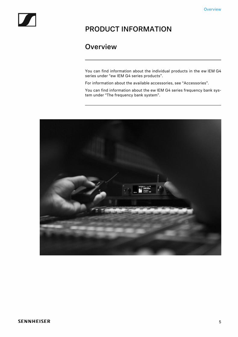
Overview
PRODUCT INFORMATION
Overview
You can find information about the individual products in the ew IEM G4series under “ew IEM G4 series products”.
For information about the available accessories, see “Accessories”.
You can find information about the ew IEM G4 series frequency bank sys-tem under “The frequency bank system”.
5

ew IEM G4 series products
ew IEM G4 series products
You can also find more information here:
• A variety of frequency variants are available from the individual prod-ucts. You can find more information under “Product variants”.
• You can find technical specifications about the individual products un-der “Specifications”.
• You can find information about installing the products under “Installingand starting up ew IEM G4 series devices”.
• You can find information about operating the products under “Usingew IEM G4 series devices”.
6
7
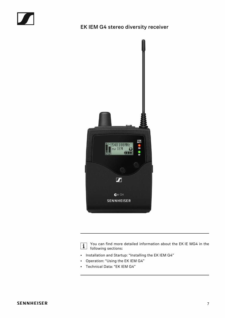
EK IEM G4 stereo diversity receiver
You can find more detailed information about the EK IE MG4 in thefollowing sections:
• Installation and Startup: “Installing the EK IEM G4”• Operation: “Using the EK IEM G4”• Technical Data: “EK IEM G4”
8
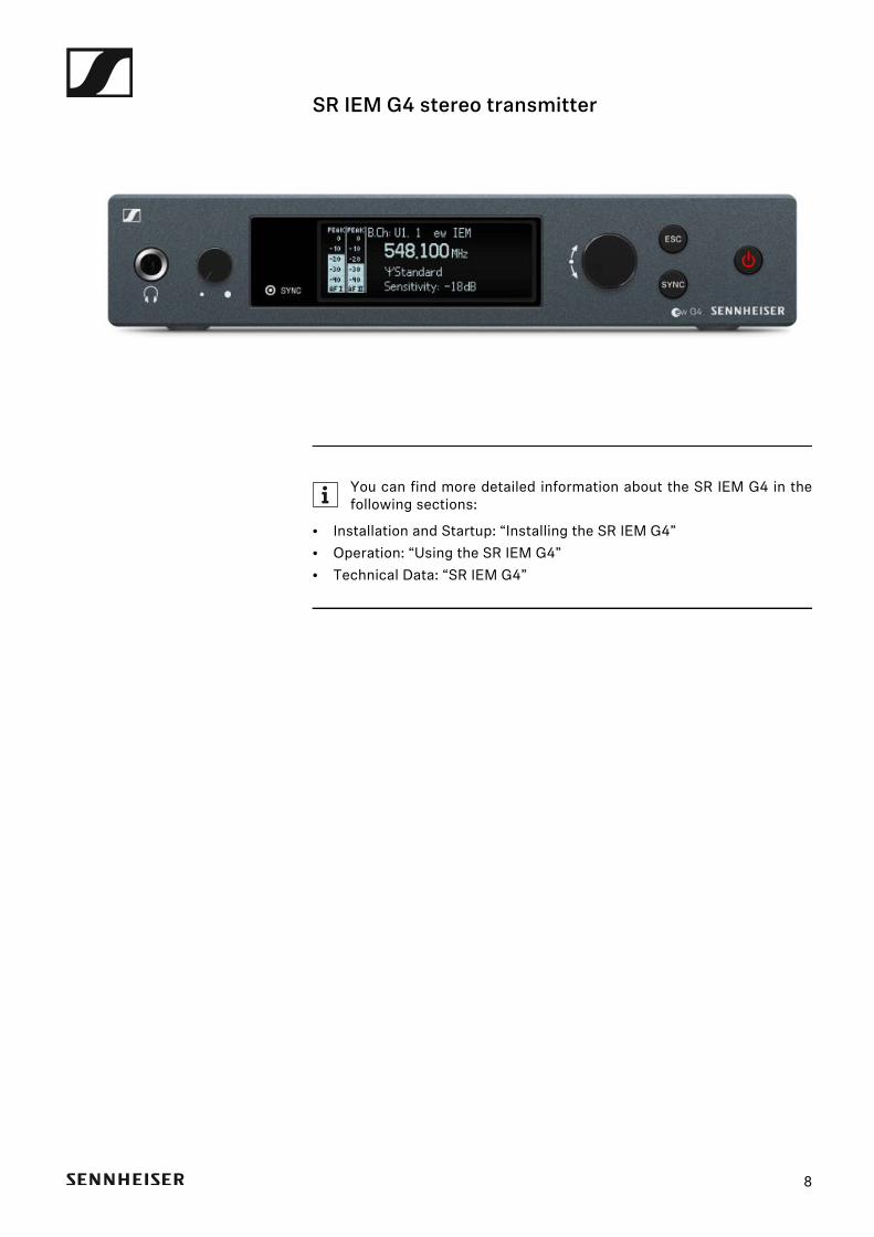
SR IEM G4 stereo transmitter
You can find more detailed information about the SR IEM G4 in thefollowing sections:
• Installation and Startup: “Installing the SR IEM G4”• Operation: “Using the SR IEM G4”• Technical Data: “SR IEM G4”
Accessories
AccessoriesA variety of accessories are available for the ew IEM G4 series.
Earphones
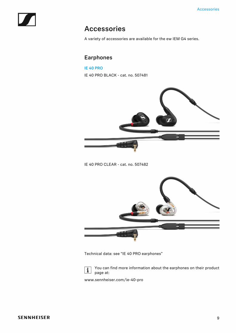
IE 40 PRO
IE 40 PRO BLACK - cat. no. 507481►
IE 40 PRO CLEAR - cat. no. 507482►
Technical data: see “IE 40 PRO earphones”
You can find more information about the earphones on their productpage at:
www.sennheiser.com/ie-40-pro
9
Accessories
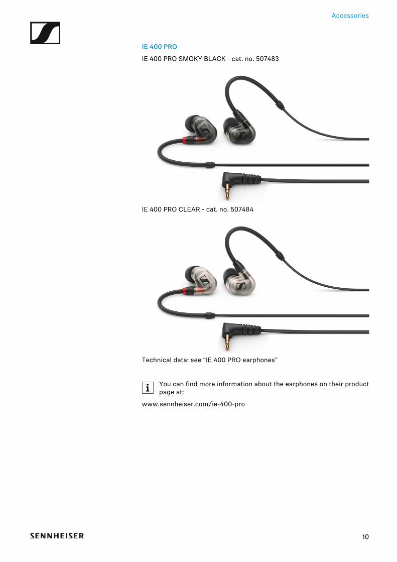
IE 400 PRO
IE 400 PRO SMOKY BLACK - cat. no. 507483►
IE 400 PRO CLEAR - cat. no. 507484►
Technical data: see “IE 400 PRO earphones”
You can find more information about the earphones on their productpage at:
www.sennheiser.com/ie-400-pro
10
Accessories
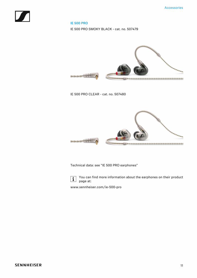
IE 500 PRO
IE 500 PRO SMOKY BLACK - cat. no. 507479►
IE 500 PRO CLEAR - cat. no. 507480►
Technical data: see “IE 500 PRO earphones”
You can find more information about the earphones on their productpage at:
www.sennheiser.com/ie-500-pro
11
Accessories
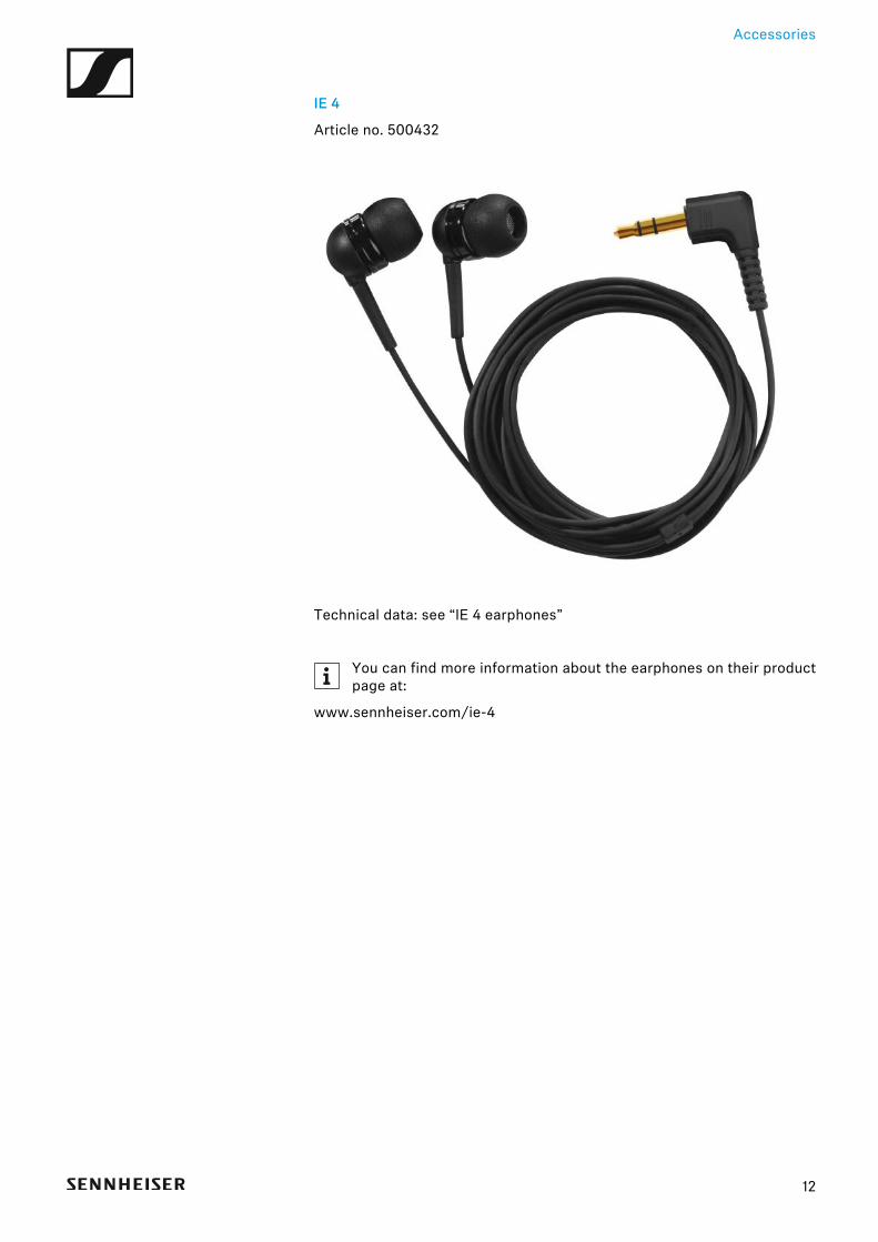
IE 4
Article no. 500432►
Technical data: see “IE 4 earphones”
You can find more information about the earphones on their productpage at:
www.sennheiser.com/ie-4
12

Accessories
Rechargeable battery and charger
BA 2015 rechargeable battery
The BA 2015 rechargeable battery is designed for use with evolution wire-less G4 series handheld transmitters, bodypack transmitters andbodypack receivers.
Article no. 009950►
L 2015 charger
The BA 2015 rechargeable battery can be charged in the L 2015 charger onits own or inside of the bodypack transmitter/bodypack receiver.
Article no. 009828►
13
Accessories
Accessories for rack mounting
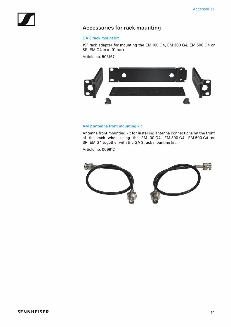
GA 3 rack mount kit
19” rack adapter for mounting the EM 100 G4, EM 300 G4, EM 500 G4 orSR IEM G4 in a 19” rack.
Article no. 503167►
AM 2 antenna front mounting kit
Antenna front mounting kit for installing antenna connections on the frontof the rack when using the EM 100 G4, EM 300 G4, EM 500 G4 orSR IEM G4 together with the GA 3 rack mounting kit.
Article no. 009912►
►
14
Accessories
Antennas and accessoriesThe following antenna components are available as accessory parts.
Omni-directional antennas
• A 1031-U, passive omni-directional antenna, article no. 004645
Directional antennas
• A 2003 UHF, passive directional antenna, article no. 003658
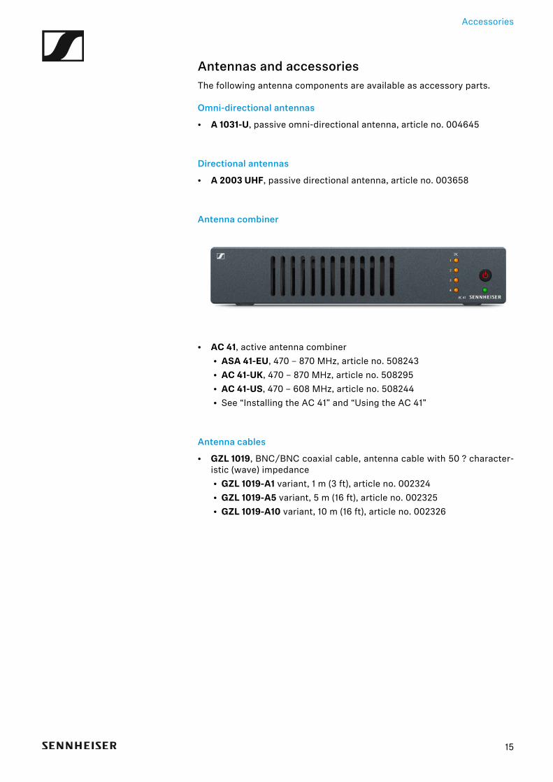
Antenna combiner►
• AC 41, active antenna combiner• ASA 41-EU, 470 – 870 MHz, article no. 508243• AC 41-UK, 470 – 870 MHz, article no. 508295• AC 41-US, 470 – 608 MHz, article no. 508244• See “Installing the AC 41” and “Using the AC 41”
Antenna cables
• GZL 1019, BNC/BNC coaxial cable, antenna cable with 50 ? character-istic (wave) impedance• GZL 1019-A1 variant, 1 m (3 ft), article no. 002324• GZL 1019-A5 variant, 5 m (16 ft), article no. 002325• GZL 1019-A10 variant, 10 m (16 ft), article no. 002326
15
The frequency bank system
16
The frequency bank systemThere are different frequency ranges in the UHF band available for trans-mission.
The following frequency ranges are available for the ew IEM G4 series:
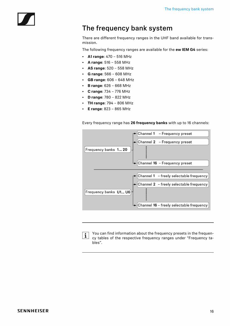
• A1 range: 470 – 516 MHz• A range: 516 – 558 MHz• AS range: 520 – 558 MHz• G range: 566 – 608 MHz• GB range: 606 – 648 MHz• B range: 626 – 668 MHz• C range: 734 – 776 MHz• D range: 780 – 822 MHz• TH range: 794 – 806 MHz• E range: 823 – 865 MHz
Every frequency range has 26 frequency banks with up to 16 channels:►
You can find information about the frequency presets in the frequen-cy tables of the respective frequency ranges under “Frequency ta-bles”.
Installing and starting up ew IEM G4 series devices
17
INSTALLATION
Installing and starting up ew IEM G4 se-ries devicesYou can find information about installing and connecting ew IEM G4 seriesdevices in the following sections.
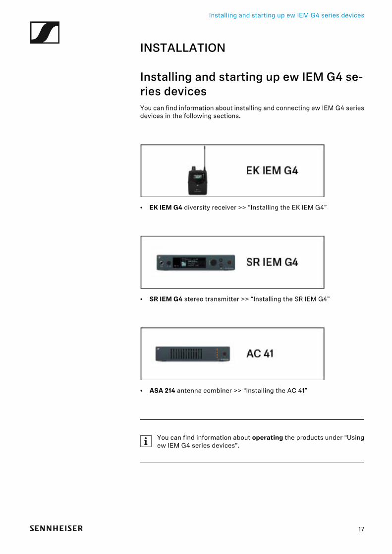
• EK IEM G4 diversity receiver >> “Installing the EK IEM G4”
• SR IEM G4 stereo transmitter >> “Installing the SR IEM G4”
• ASA 214 antenna combiner >> “Installing the AC 41”
You can find information about operating the products under “Usingew IEM G4 series devices”.

Installing the EK IEM G4
Installing the EK IEM G4These sections contain detailed information about installing and startingup the EK IEM G4.
You can find information about operating the EK IEM G4 under “Using theEK IEM G4”.
18
Installing the EK IEM G4
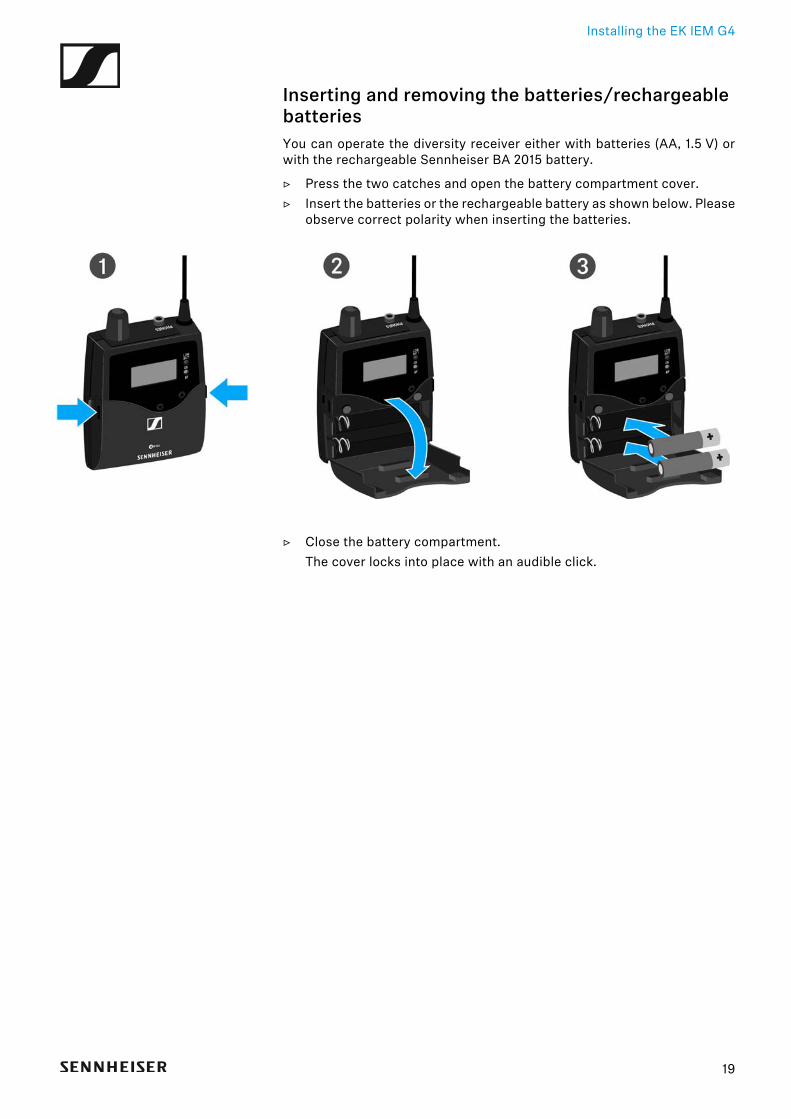
Inserting and removing the batteries/rechargeable batteriesYou can operate the diversity receiver either with batteries (AA, 1.5 V) orwith the rechargeable Sennheiser BA 2015 battery.
▷ Press the two catches and open the battery compartment cover.▷ Insert the batteries or the rechargeable battery as shown below. Please
observe correct polarity when inserting the batteries.
▷ Close the battery compartment.The cover locks into place with an audible click.
19
Installing the EK IEM G4
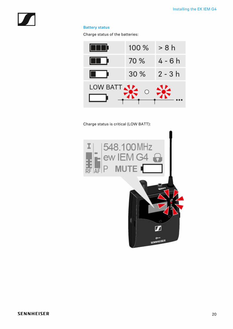
Battery status
Charge status of the batteries:►
Charge status is critical (LOW BATT):►
20
Installing the EK IEM G4
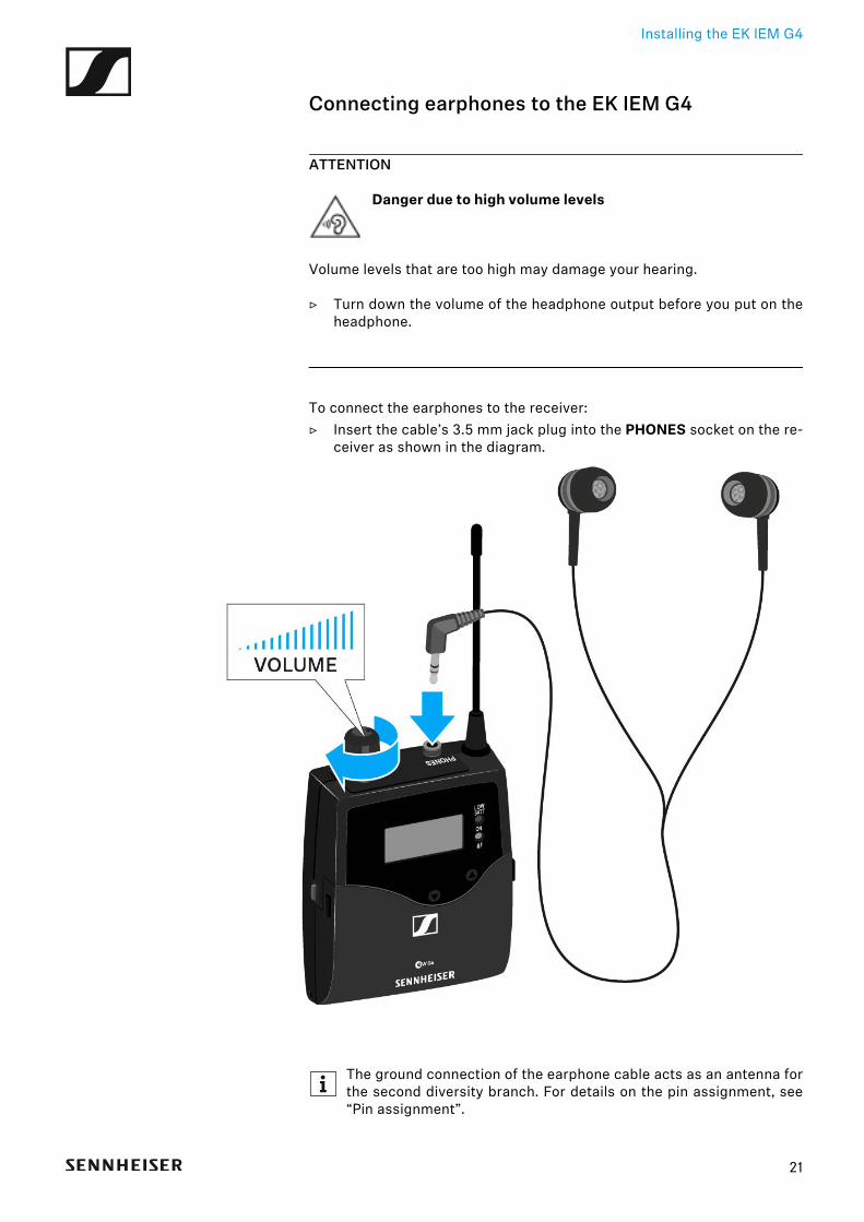
Connecting earphones to the EK IEM G4
ATTENTION
Danger due to high volume levels
Volume levels that are too high may damage your hearing.
▷ Turn down the volume of the headphone output before you put on theheadphone.
To connect the earphones to the receiver:▷ Insert the cable’s 3.5 mm jack plug into the PHONES socket on the re-
ceiver as shown in the diagram.►
The ground connection of the earphone cable acts as an antenna forthe second diversity branch. For details on the pin assignment, see“Pin assignment”.
21
Installing the EK IEM G4
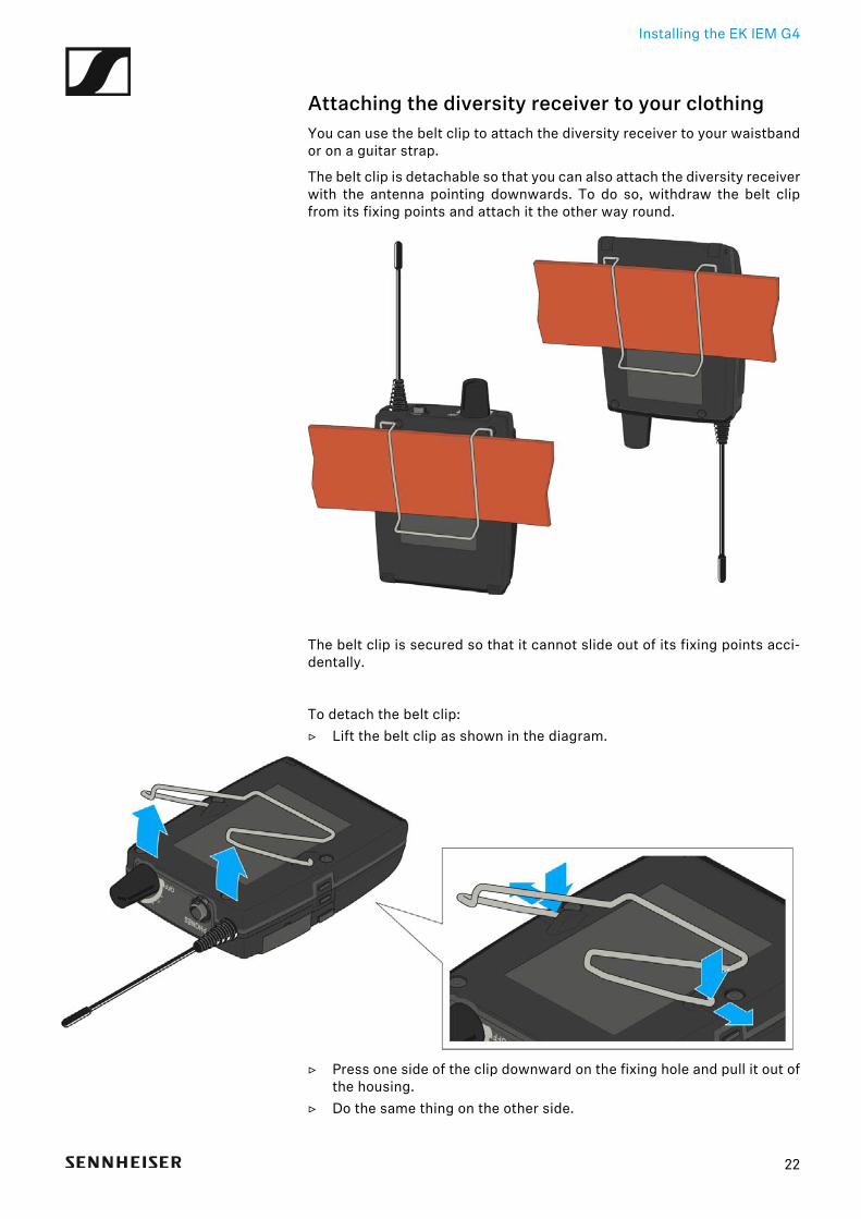
Attaching the diversity receiver to your clothingYou can use the belt clip to attach the diversity receiver to your waistbandor on a guitar strap.
The belt clip is detachable so that you can also attach the diversity receiverwith the antenna pointing downwards. To do so, withdraw the belt clipfrom its fixing points and attach it the other way round.►
The belt clip is secured so that it cannot slide out of its fixing points acci-dentally.
To detach the belt clip:▷ Lift the belt clip as shown in the diagram.►
▷ Press one side of the clip downward on the fixing hole and pull it out ofthe housing.
▷ Do the same thing on the other side.
22

Installing the SR IEM G4
Installing the SR IEM G4These sections contain detailed information about installing and startingup the SR IEM G4.
You can find information about operating the SR IEM G4 under “Using theSR IEM G4”.
23
Installing the SR IEM G4
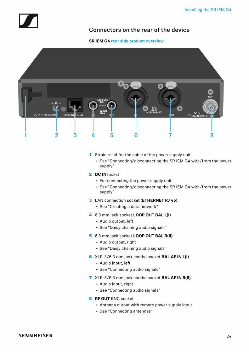
Connectors on the rear of the device
SR IEM G4 rear side product overview►
1 Strain relief for the cable of the power supply unit• See “Connecting/disconnecting the SR IEM G4 with/from the power
supply”
2 DC INsocket• For connecting the power supply unit• See “Connecting/disconnecting the SR IEM G4 with/from the power
supply”
3 LAN connection socket (ETHERNET RJ 45)• See “Creating a data network”
4 6.3 mm jack socket LOOP OUT BAL L(I)• Audio output, left• See “Daisy chaining audio signals”
5 6.3 mm jack socket LOOP OUT BAL R(II)• Audio output, right• See “Daisy chaining audio signals”
6 XLR-3/6.3 mm jack combo socket BAL AF IN L(I)• Audio input, left• See “Connecting audio signals”
7 XLR-3/6.3 mm jack combo socket BAL AF IN R(II)• Audio input, right• See “Connecting audio signals”
8 RF OUT BNC socket• Antenna output with remote power supply input• See “Connecting antennas”
24
Installing the SR IEM G4
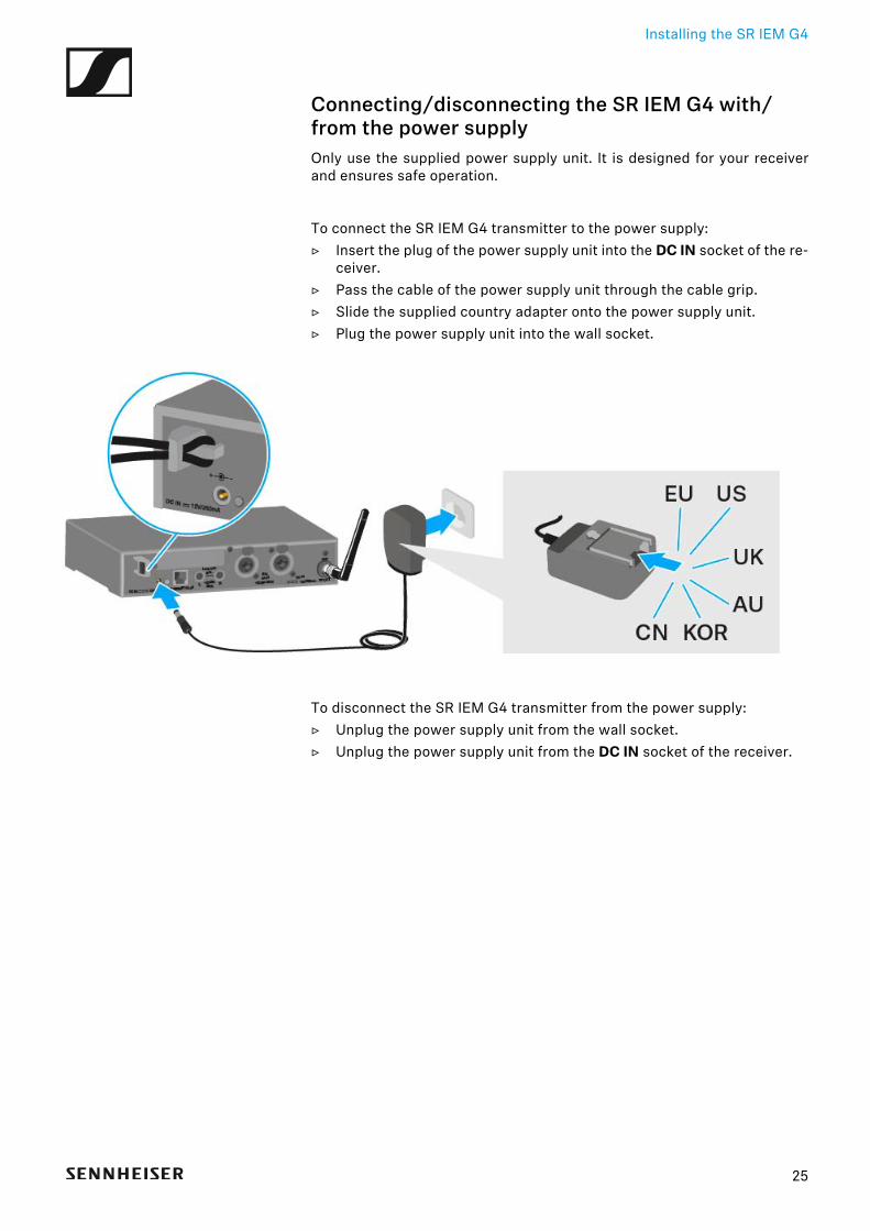
Connecting/disconnecting the SR IEM G4 with/from the power supplyOnly use the supplied power supply unit. It is designed for your receiverand ensures safe operation.
To connect the SR IEM G4 transmitter to the power supply:▷ Insert the plug of the power supply unit into the DC IN socket of the re-
ceiver.▷ Pass the cable of the power supply unit through the cable grip.▷ Slide the supplied country adapter onto the power supply unit.▷ Plug the power supply unit into the wall socket.
To disconnect the SR IEM G4 transmitter from the power supply:▷ Unplug the power supply unit from the wall socket.▷ Unplug the power supply unit from the DC IN socket of the receiver.
25
Installing the SR IEM G4
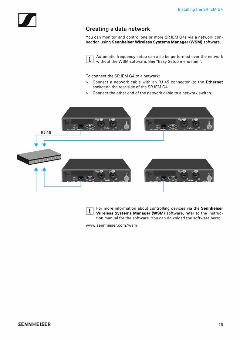
Creating a data networkYou can monitor and control one or more SR IEM G4s via a network con-nection using Sennheiser Wireless Systems Manager (WSM) software.
Automatic frequency setup can also be performed over the networkwithout the WSM software. See “Easy Setup menu item”.
To connect the SR IEM G4 to a network:▷ Connect a network cable with an RJ-45 connector (to the Ethernet
socket on the rear side of the SR IEM G4.▷ Connect the other end of the network cable to a network switch.
►
For more information about controlling devices via the SennheiserWireless Systems Manager (WSM) software, refer to the instruc-tion manual for the software. You can download the software here:
www.sennheiser.com/wsm
26
Installing the SR IEM G4
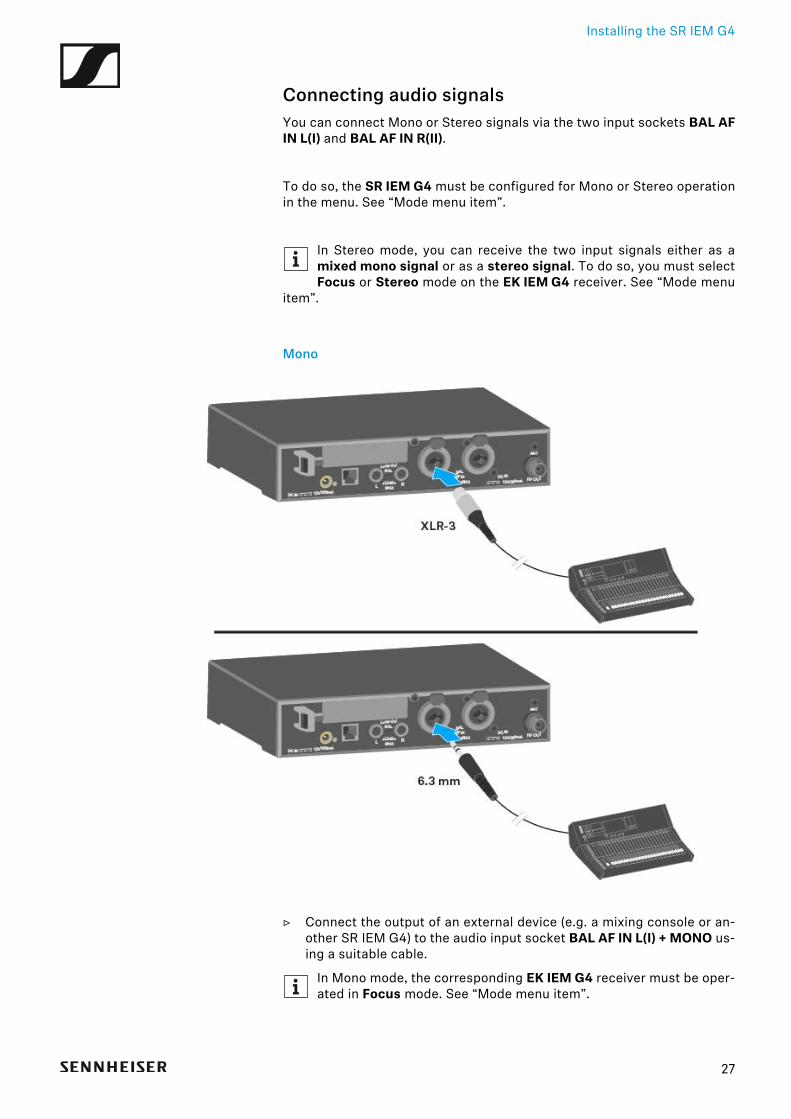
Connecting audio signalsYou can connect Mono or Stereo signals via the two input sockets BAL AFIN L(I) and BAL AF IN R(II).
To do so, the SR IEM G4 must be configured for Mono or Stereo operationin the menu. See “Mode menu item”.
In Stereo mode, you can receive the two input signals either as amixed mono signal or as a stereo signal. To do so, you must selectFocus or Stereo mode on the EK IEM G4 receiver. See “Mode menu
item”.
Mono
▷ Connect the output of an external device (e.g. a mixing console or an-other SR IEM G4) to the audio input socket BAL AF IN L(I) + MONO us-ing a suitable cable.
In Mono mode, the corresponding EK IEM G4 receiver must be oper-ated in Focus mode. See “Mode menu item”.
27
Installing the SR IEM G4
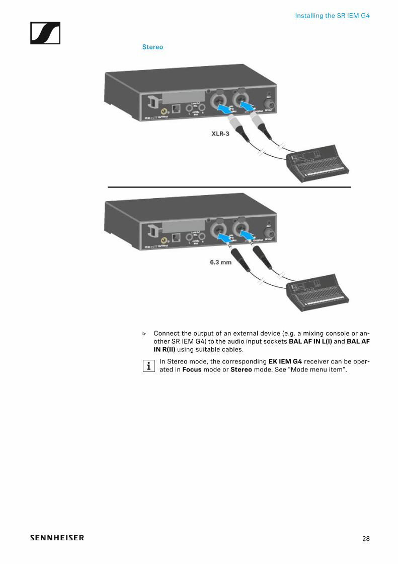
Stereo
▷ Connect the output of an external device (e.g. a mixing console or an-other SR IEM G4) to the audio input sockets BAL AF IN L(I) and BAL AFIN R(II) using suitable cables.
In Stereo mode, the corresponding EK IEM G4 receiver can be oper-ated in Focus mode or Stereo mode. See “Mode menu item”.
28
Installing the SR IEM G4
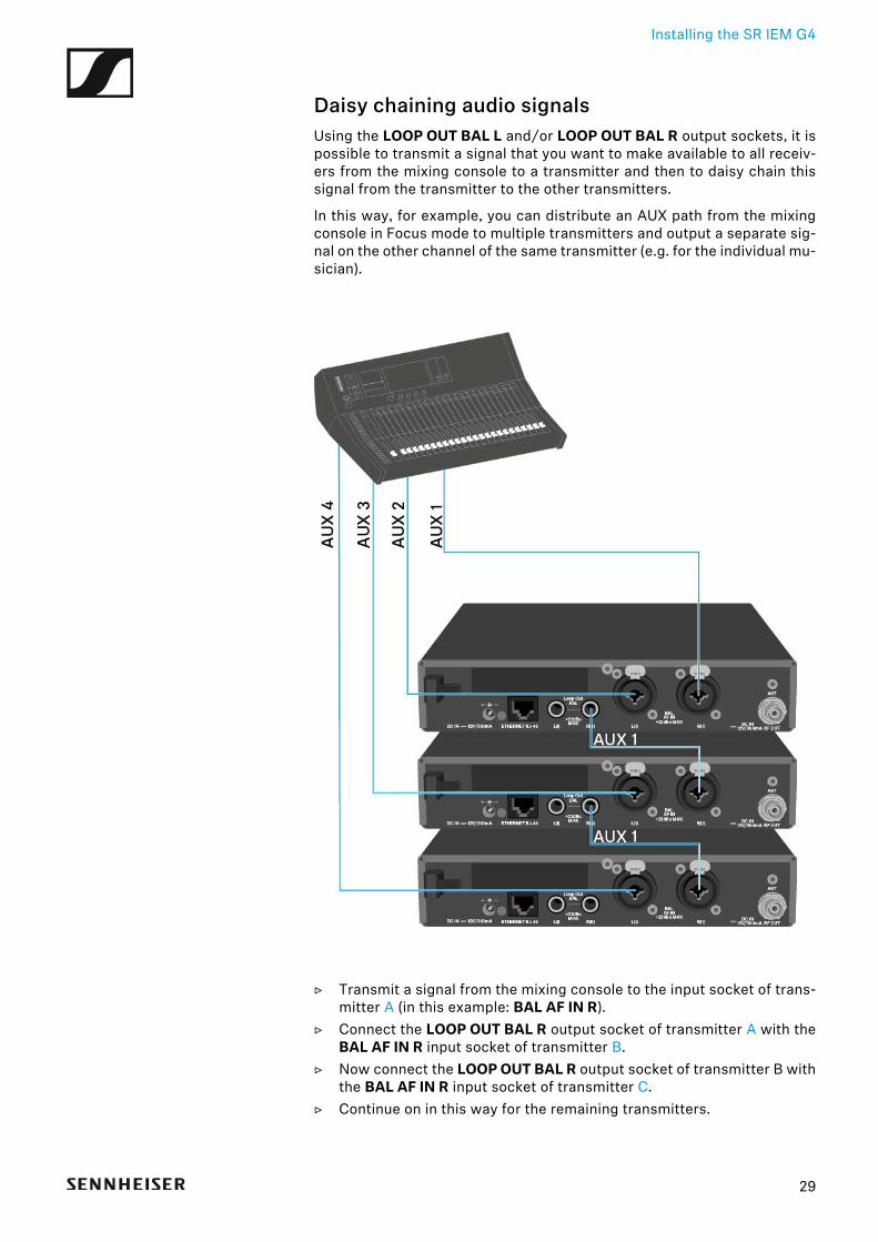
Daisy chaining audio signalsUsing the LOOP OUT BAL L and/or LOOP OUT BAL R output sockets, it ispossible to transmit a signal that you want to make available to all receiv-ers from the mixing console to a transmitter and then to daisy chain thissignal from the transmitter to the other transmitters.
In this way, for example, you can distribute an AUX path from the mixingconsole in Focus mode to multiple transmitters and output a separate sig-nal on the other channel of the same transmitter (e.g. for the individual mu-sician).
▷ Transmit a signal from the mixing console to the input socket of trans-mitter A (in this example: BAL AF IN R).
▷ Connect the LOOP OUT BAL R output socket of transmitter A with theBAL AF IN R input socket of transmitter B.
▷ Now connect the LOOP OUT BAL R output socket of transmitter B withthe BAL AF IN R input socket of transmitter C.
▷ Continue on in this way for the remaining transmitters.
29
Installing the SR IEM G4
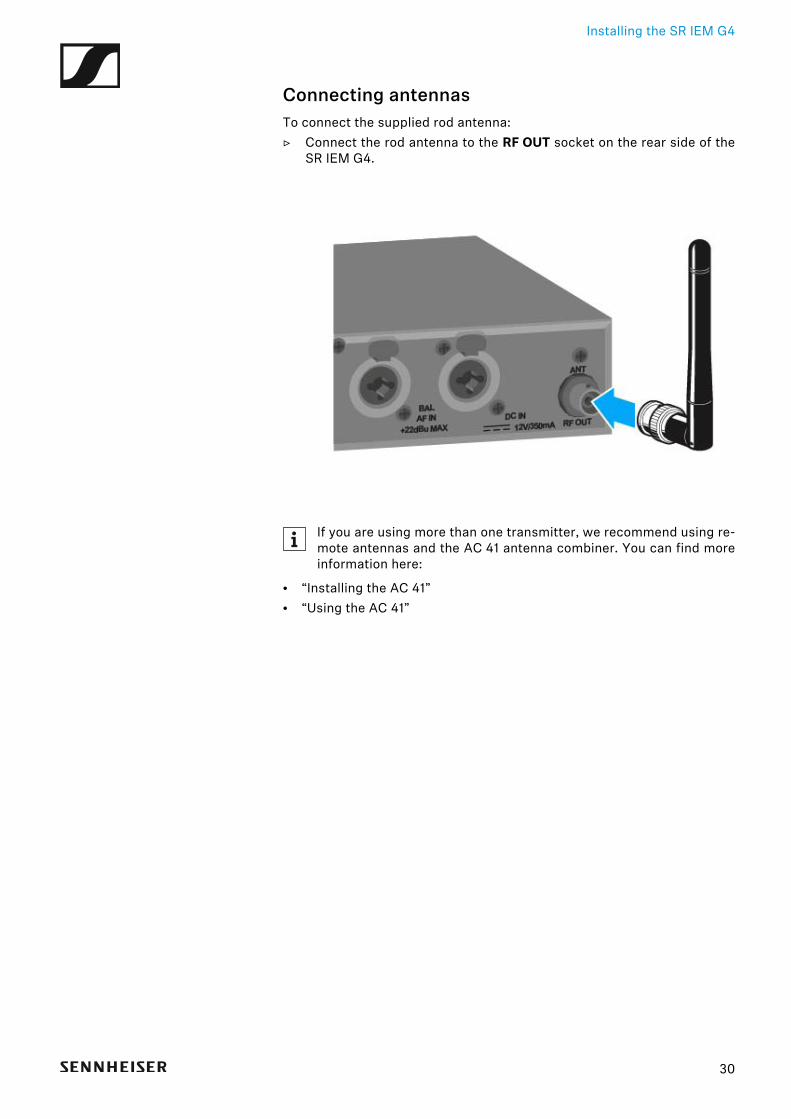
Connecting antennasTo connect the supplied rod antenna:▷ Connect the rod antenna to the RF OUT socket on the rear side of the
SR IEM G4.
If you are using more than one transmitter, we recommend using re-mote antennas and the AC 41 antenna combiner. You can find moreinformation here:
• “Installing the AC 41”• “Using the AC 41”
30
Installing the SR IEM G4
Installing the SR IEM G4 in a rack
CAUTION
Rack mounting poses risks
When installing the device in a closed or multi-rack assembly, please con-sider that, during operation, the ambient temperature, the mechanicalloading and the electrical potentials will be different from those of deviceswhich are not mounted into a rack.
▷ Make sure that the ambient temperature within the rack does not ex-ceed the permissible temperature limit specified in the specifications.See “Specifications”.
▷ Ensure sufficient ventilation; if necessary, provide additional ventila-tion.
▷ Make sure that the mechanical loading of the rack is even.
▷ When connecting to the power supply system, observe the informationindicated on the type plate. Avoid circuit overloading. If necessary, pro-vide overcurrent protection.
▷ When rack mounting, please note that intrinsically harmless leakagecurrents of the individual power supply units may accumulate, therebyexceeding the allowable limit value. As a remedy, ground the rack viaan additional ground connection.
31
Installing the SR IEM G4
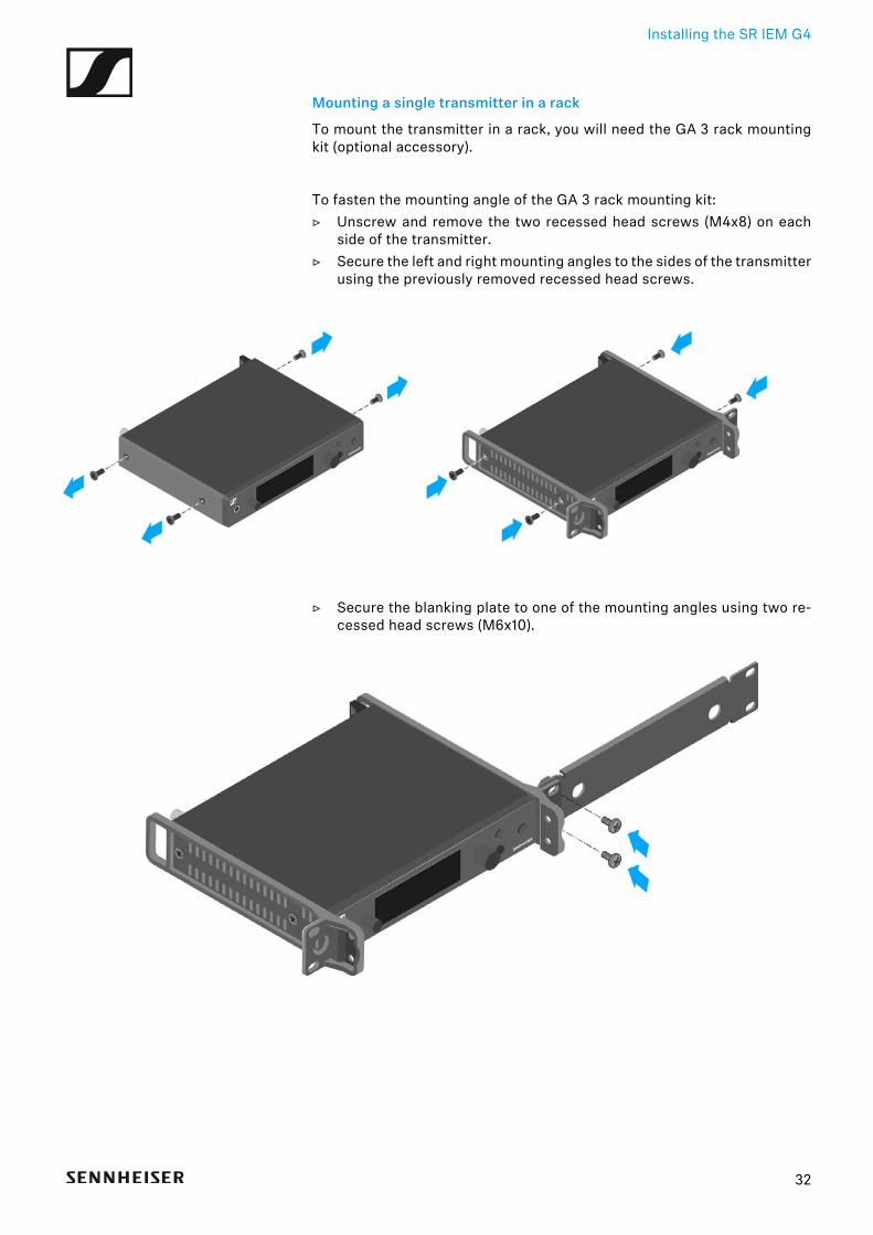
Mounting a single transmitter in a rack
To mount the transmitter in a rack, you will need the GA 3 rack mountingkit (optional accessory).
To fasten the mounting angle of the GA 3 rack mounting kit:▷ Unscrew and remove the two recessed head screws (M4x8) on each
side of the transmitter.▷ Secure the left and right mounting angles to the sides of the transmitter
using the previously removed recessed head screws.
►
▷ Secure the blanking plate to one of the mounting angles using two re-cessed head screws (M6x10).
32
Installing the SR IEM G4
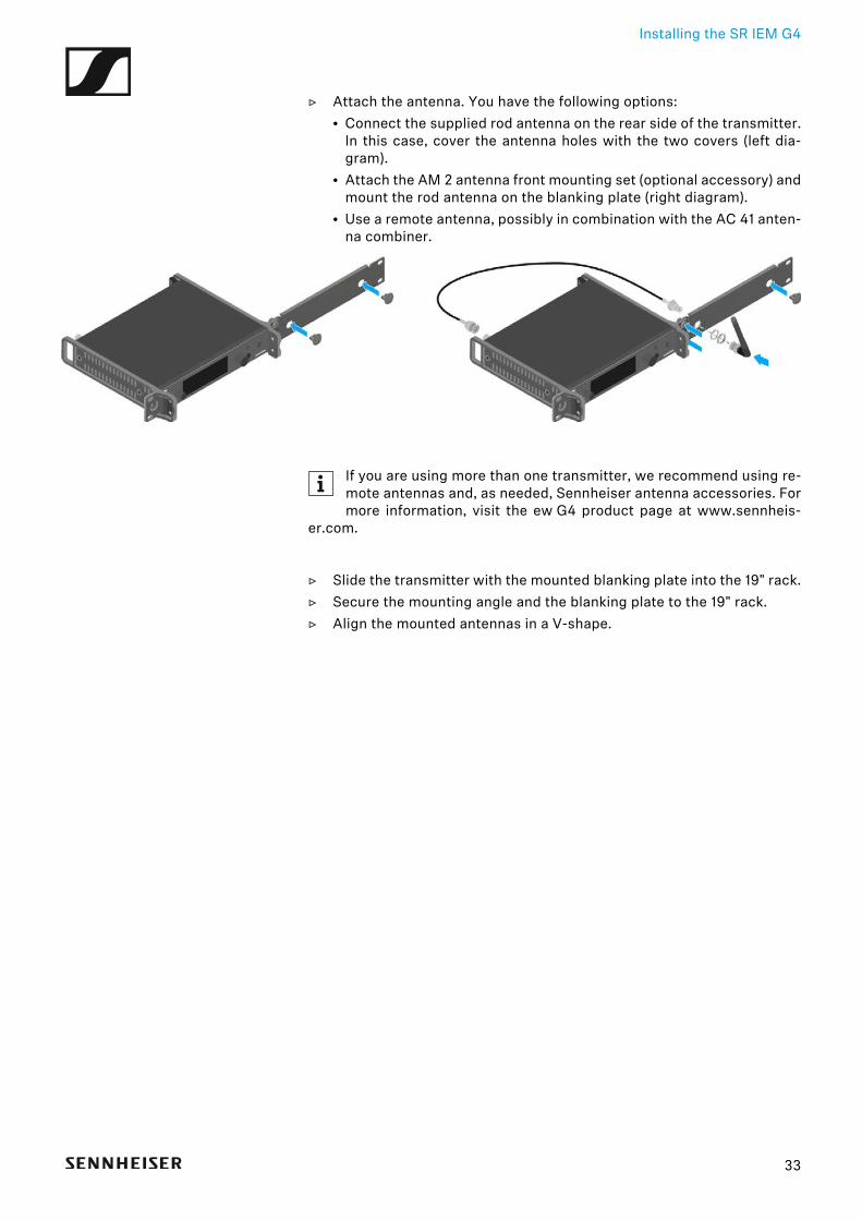
▷ Attach the antenna. You have the following options:• Connect the supplied rod antenna on the rear side of the transmitter.
In this case, cover the antenna holes with the two covers (left dia-gram).
• Attach the AM 2 antenna front mounting set (optional accessory) andmount the rod antenna on the blanking plate (right diagram).
• Use a remote antenna, possibly in combination with the AC 41 anten-na combiner.
►
If you are using more than one transmitter, we recommend using re-mote antennas and, as needed, Sennheiser antenna accessories. Formore information, visit the ew G4 product page at www.sennheis-
er.com.
▷ Slide the transmitter with the mounted blanking plate into the 19" rack.▷ Secure the mounting angle and the blanking plate to the 19" rack.▷ Align the mounted antennas in a V-shape.
33
Installing the SR IEM G4
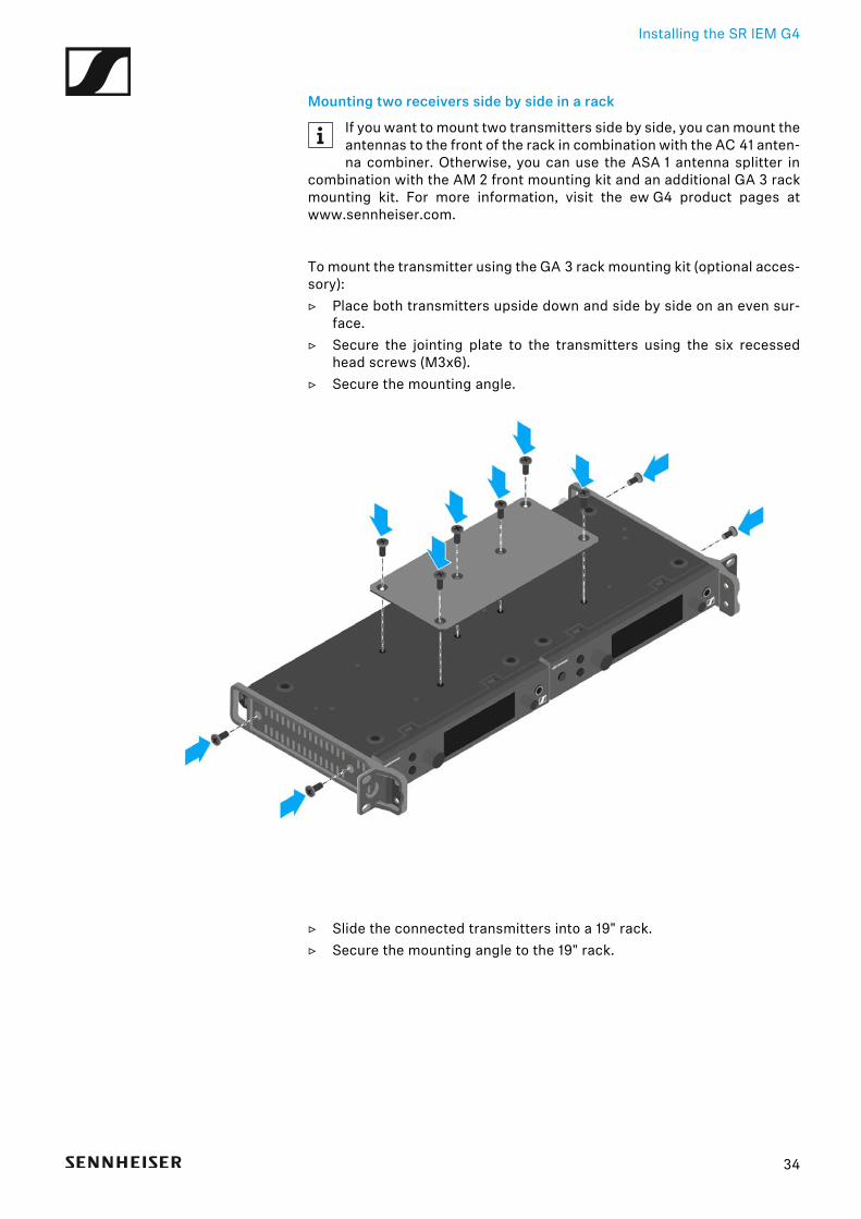
Mounting two receivers side by side in a rack
If you want to mount two transmitters side by side, you can mount theantennas to the front of the rack in combination with the AC 41 anten-na combiner. Otherwise, you can use the ASA 1 antenna splitter in
combination with the AM 2 front mounting kit and an additional GA 3 rackmounting kit. For more information, visit the ew G4 product pages atwww.sennheiser.com.
To mount the transmitter using the GA 3 rack mounting kit (optional acces-sory):▷ Place both transmitters upside down and side by side on an even sur-
face.▷ Secure the jointing plate to the transmitters using the six recessed
head screws (M3x6).▷ Secure the mounting angle.
►
▷ Slide the connected transmitters into a 19" rack.▷ Secure the mounting angle to the 19" rack.
34

Installing the AC 41
Installing the AC 41These sections contain detailed information about installing and startingup the AC 41.
You can find information about operating the AC 41 under “Using theAC 41”.
35
Installing the AC 41
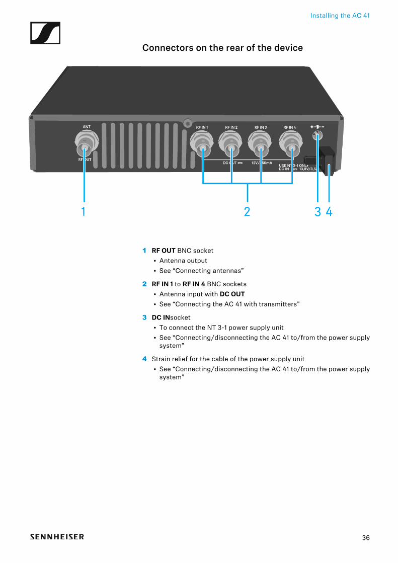
Connectors on the rear of the device
1 RF OUT BNC socket• Antenna output• See “Connecting antennas”
2 RF IN 1 to RF IN 4 BNC sockets• Antenna input with DC OUT• See “Connecting the AC 41 with transmitters”
3 DC INsocket• To connect the NT 3-1 power supply unit• See “Connecting/disconnecting the AC 41 to/from the power supply
system”
4 Strain relief for the cable of the power supply unit• See “Connecting/disconnecting the AC 41 to/from the power supply
system”
36
Installing the AC 41
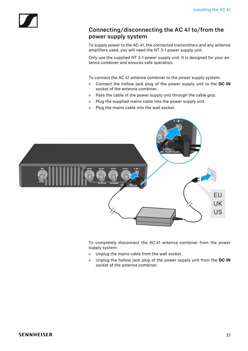
Connecting/disconnecting the AC 41 to/from the power supply systemTo supply power to the AC 41, the connected transmitters and any antennaamplifiers used, you will need the NT 3-1 power supply unit.
Only use the supplied NT 3-1 power supply unit. It is designed for your an-tenna combiner and ensures safe operation.
To connect the AC 41 antenna combiner to the power supply system:▷ Connect the hollow jack plug of the power supply unit to the DC IN
socket of the antenna combiner.▷ Pass the cable of the power supply unit through the cable grip.▷ Plug the supplied mains cable into the power supply unit.▷ Plug the mains cable into the wall socket.
To completely disconnect the AC 41 antenna combiner from the powersupply system:▷ Unplug the mains cable from the wall socket.▷ Unplug the hollow jack plug of the power supply unit from the DC IN
socket of the antenna combiner.
37
Installing the AC 41
Connecting the AC 41 with transmittersYou can connect and operate up to four stereo transmitters to the AC 41.
The following transmitters are compatible:
evolution wireless G4:• SR IEM G4
evolution wireless G3:
• EK 300 IEM G3
2000 IEM series:
• SR 2000 IEM (with its own power supply)• SR 2050 IEM (with its own power supply)
Due to legal reasons, the transmission power of the connectedtransmitter must be set to a maximum of 30 mW (standard) when op-erating the AC 41. See “Advanced > RF Power menu item”.
38
Installing the AC 41
To connect the transmitter to the antenna combiner:▷ Connect one of the RF IN sockets of the AC 41 with the RF OUT jacks of
a transmitter.▷ Repeat the previous step until all four transmitters are connected to the
antenna combiner.▷ Connect the AC 41 to the power supply system (see “Connecting/dis-
connecting the AC 41 to/from the power supply system”).The LEDs light up (see “Meaning of the LEDs”).
The SR IEM G4 and SR 300 IEM G3 transmitters are supplied withvoltage via the RF IN input sockets of the AC 41.
39
Installing the AC 41
Connecting antennasFor more information about antennas and antenna accessories, see“Antennas and accessories”.
In order to ensure optimal reception even in the case of poor receptionconditions, we recommend using remote antennas.
To connect a remote antenna:▷ Connect the antenna and transmitter with a low-attenuation 50-Ω ca-
ble.▷ Use the shortest antenna cable possible with few intermediary connec-
tions. The cable and transmitter will attenuate the wanted signal.▷ Place the antenna in the room where the transmission is taking place.▷ Maintain a distance of at least 1 m (3 ft) between the antenna and any
metal objects.
40
Installing the AC 41
Installing the AC 41 in a rack
CAUTION
Rack mounting poses risks
When installing the device in a closed or multi-rack assembly, please con-sider that, during operation, the ambient temperature, the mechanicalloading and the electrical potentials will be different from those of deviceswhich are not mounted into a rack.
▷ Make sure that the ambient temperature within the rack does not ex-ceed the permissible temperature limit specified in the specifications.See “Specifications”.
▷ Ensure sufficient ventilation; if necessary, provide additional ventila-tion.
▷ Make sure that the mechanical loading of the rack is even.
▷ When connecting to the power supply system, observe the informationindicated on the type plate. Avoid circuit overloading. If necessary, pro-vide overcurrent protection.
▷ When rack mounting, please note that intrinsically harmless leakagecurrents of the individual power supply units may accumulate, therebyexceeding the allowable limit value. As a remedy, ground the rack viaan additional ground connection.
41
Installing the AC 41
Mounting a single antenna combiner in a rack
To mount the antenna combiner in a rack, you will need the GA 3 rackmounting kit (optional accessory).
To fasten the mounting angle of the GA 3 rack mounting kit:▷ Unscrew and remove the two recessed head screws (M4x8) on each
side of the antenna combiner.▷ Secure the mounting angles to the sides of the antenna combiner using
the previously removed recessed head screws.
►
▷ Secure the blanking plate to one of the mounting angles using two re-cessed head screws (M6x10).
▷ Cover the antenna holes with the two covers.
►
▷ Slide the antenna combiner with the mounted blanking plate into the19" rack.
▷ Secure the mounting angle and the blanking plate to the 19" rack.
42
Installing the AC 41
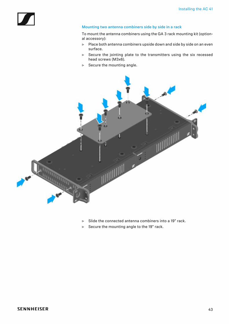
Mounting two antenna combiners side by side in a rack
To mount the antenna combiners using the GA 3 rack mounting kit (option-al accessory):▷ Place both antenna combiners upside down and side by side on an even
surface.▷ Secure the jointing plate to the transmitters using the six recessed
head screws (M3x6).▷ Secure the mounting angle.
▷ Slide the connected antenna combiners into a 19" rack.▷ Secure the mounting angle to the 19" rack.
43
Using ew IEM G4 series devices
OPERATION
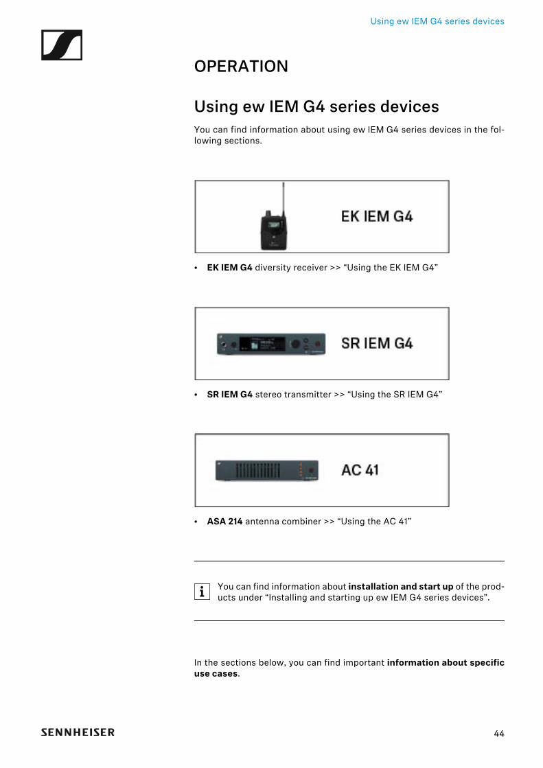
Using ew IEM G4 series devicesYou can find information about using ew IEM G4 series devices in the fol-lowing sections.
• EK IEM G4 diversity receiver >> “Using the EK IEM G4”
• SR IEM G4 stereo transmitter >> “Using the SR IEM G4”
• ASA 214 antenna combiner >> “Using the AC 41”
You can find information about installation and start up of the prod-ucts under “Installing and starting up ew IEM G4 series devices”.
In the sections below, you can find important information about specificuse cases.
44
Using ew IEM G4 series devices
• Establishing a radio link between the transmitter and receiver >> “Es-tablishing a radio link”
• Synchronizing the receiver settings to the transmitter >> “Synchroniz-ing devices”
• Using the menu of the receiver >> “Displays on the EK IEM G4 displaypanel”
• Using the menu of the transmitter >> “Displays on the SR IEM G4 dis-play panel”
45

Using the EK IEM G4
Using the EK IEM G4These sections contain detailed information about using the EK IEM G4.
You can find information on installation and startup of the EK IEM G4 under“Installing the EK IEM G4”.
46
Using the EK IEM G4
Operating elements of the EK IEM G4 diversity re-ceiver
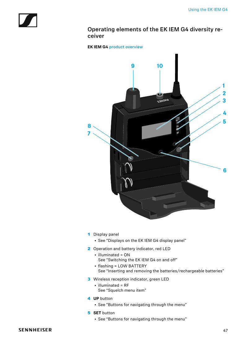
EK IEM G4 product overview►
1 Display panel• See “Displays on the EK IEM G4 display panel”
2 Operation and battery indicator, red LED• illuminated = ON
See “Switching the EK IEM G4 on and off”• flashing = LOW BATTERY
See “Inserting and removing the batteries/rechargeable batteries”
3 Wireless reception indicator, green LED• illuminated = RF
See “Squelch menu item”
4 UP button• See “Buttons for navigating through the menu”
5 SET button• See “Buttons for navigating through the menu”
47
Using the EK IEM G4
6 DOWN button• See “Buttons for navigating through the menu”
7 ESC button• See “Buttons for navigating through the menu”
8 Infra-red interface• See “Synchronizing devices”
9 Volume control with on/off switch• See “Connecting earphones to the EK IEM G4”• Switch the receiver on/off
See “Switching the EK IEM G4 on and off”
103.5 mm PHONES jack socket, lockable• Jack for connecting an earphone
See “Connecting earphones to the EK IEM G4”
48
Using the EK IEM G4
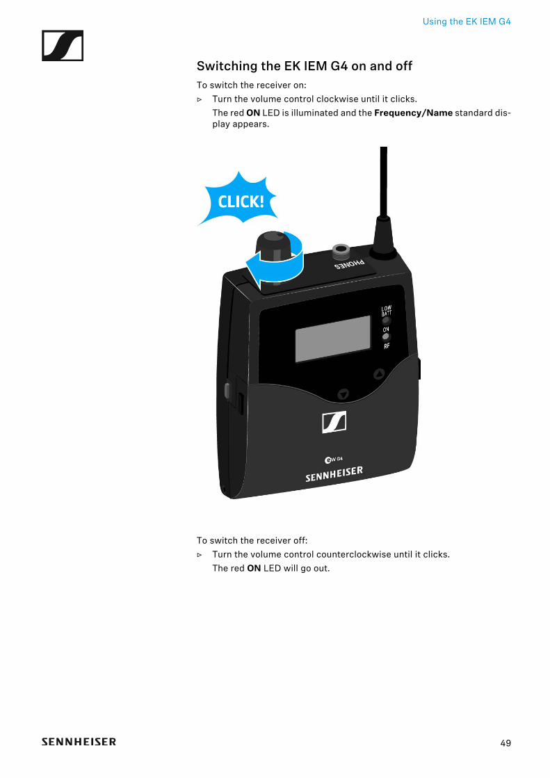
Switching the EK IEM G4 on and offTo switch the receiver on:▷ Turn the volume control clockwise until it clicks.
The red ON LED is illuminated and the Frequency/Name standard dis-play appears.
To switch the receiver off:▷ Turn the volume control counterclockwise until it clicks.
The red ON LED will go out.
49
Using the EK IEM G4
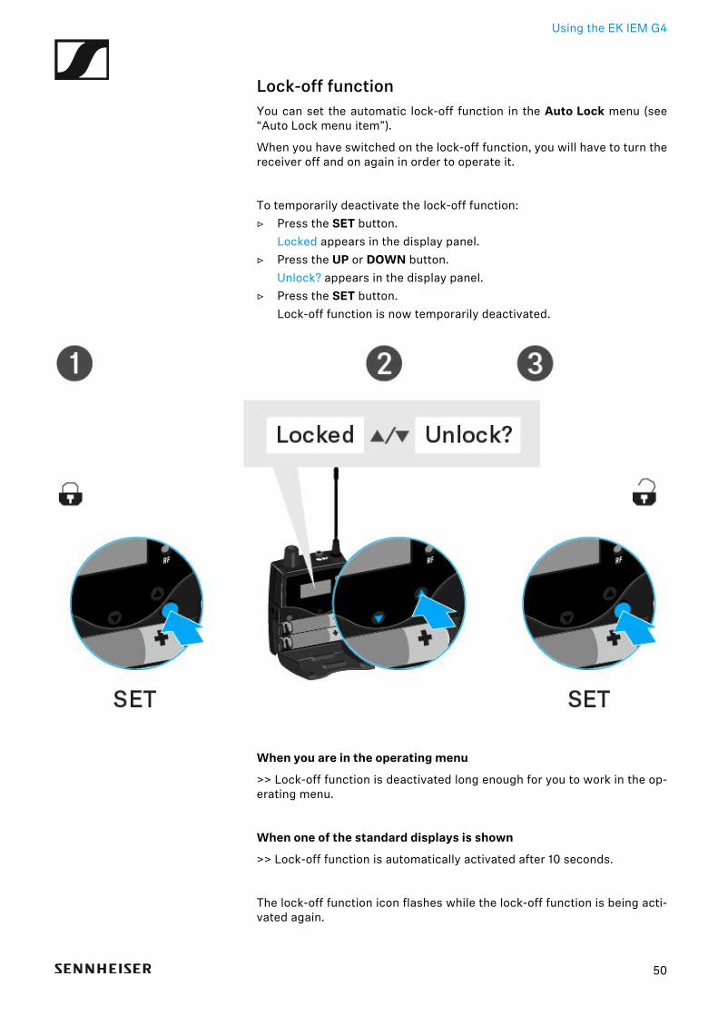
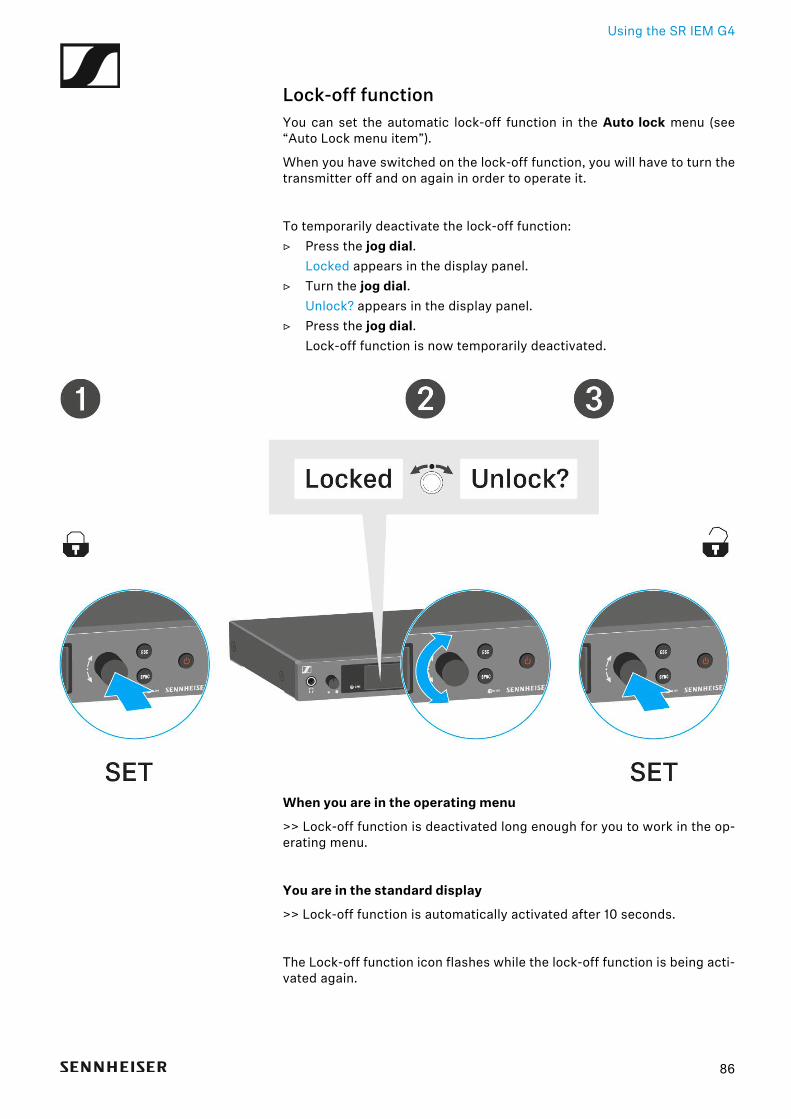
Lock-off functionYou can set the automatic lock-off function in the Auto Lock menu (see“Auto Lock menu item”).
When you have switched on the lock-off function, you will have to turn thereceiver off and on again in order to operate it.
To temporarily deactivate the lock-off function:▷ Press the SET button.
Locked appears in the display panel.▷ Press the UP or DOWN button.
Unlock? appears in the display panel.▷ Press the SET button.
Lock-off function is now temporarily deactivated.
When you are in the operating menu
>> Lock-off function is deactivated long enough for you to work in the op-erating menu.
When one of the standard displays is shown
>> Lock-off function is automatically activated after 10 seconds.
The lock-off function icon flashes while the lock-off function is being acti-vated again.
50

Using the EK IEM G4
Displays on the EK IEM G4 display panel
Status information such as reception quality, battery status, audio level,etc. is displayed on the home screen of the display panel. See “Homescreen”.
The display panel also displays the operating menu, which you can use toconfigure all of the settings. See “Setting options in the menu”.
51
Using the EK IEM G4
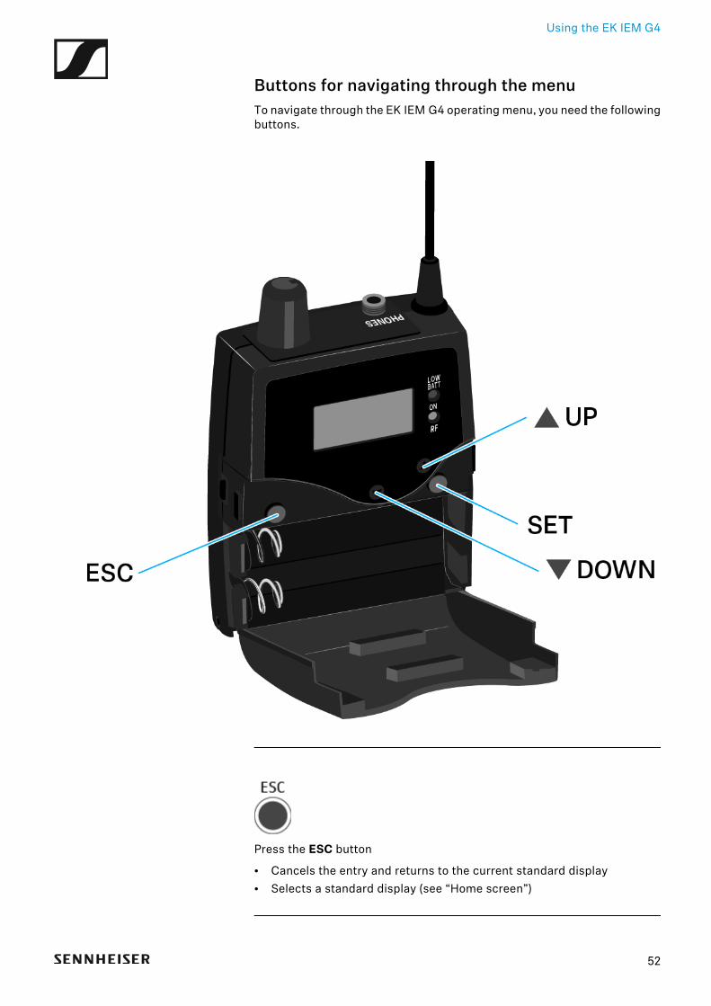
Buttons for navigating through the menuTo navigate through the EK IEM G4 operating menu, you need the followingbuttons.
►
Press the ESC button
• Cancels the entry and returns to the current standard display• Selects a standard display (see “Home screen”)
52
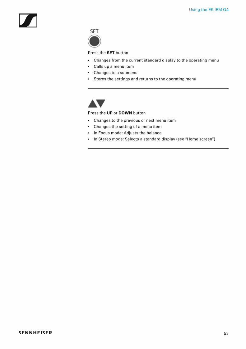
Using the EK IEM G4
►
Press the SET button
• Changes from the current standard display to the operating menu• Calls up a menu item• Changes to a submenu• Stores the settings and returns to the operating menu
►
Press the UP or DOWN button
• Changes to the previous or next menu item• Changes the setting of a menu item• In Focus mode: Adjusts the balance• In Stereo mode: Selects a standard display (see “Home screen”)
53
Using the EK IEM G4
Home screenAfter you switch on the receiver, the display panel initially displays theSennheiser logo. After a short time, the home screen is then displayed.
The home screen has three different standard displays.
▷ On the home screen, press the ESC button to switch between the stan-dard displays.In Stereo mode, you can also press the UP/DOWN button to switch be-tween the standard displays.
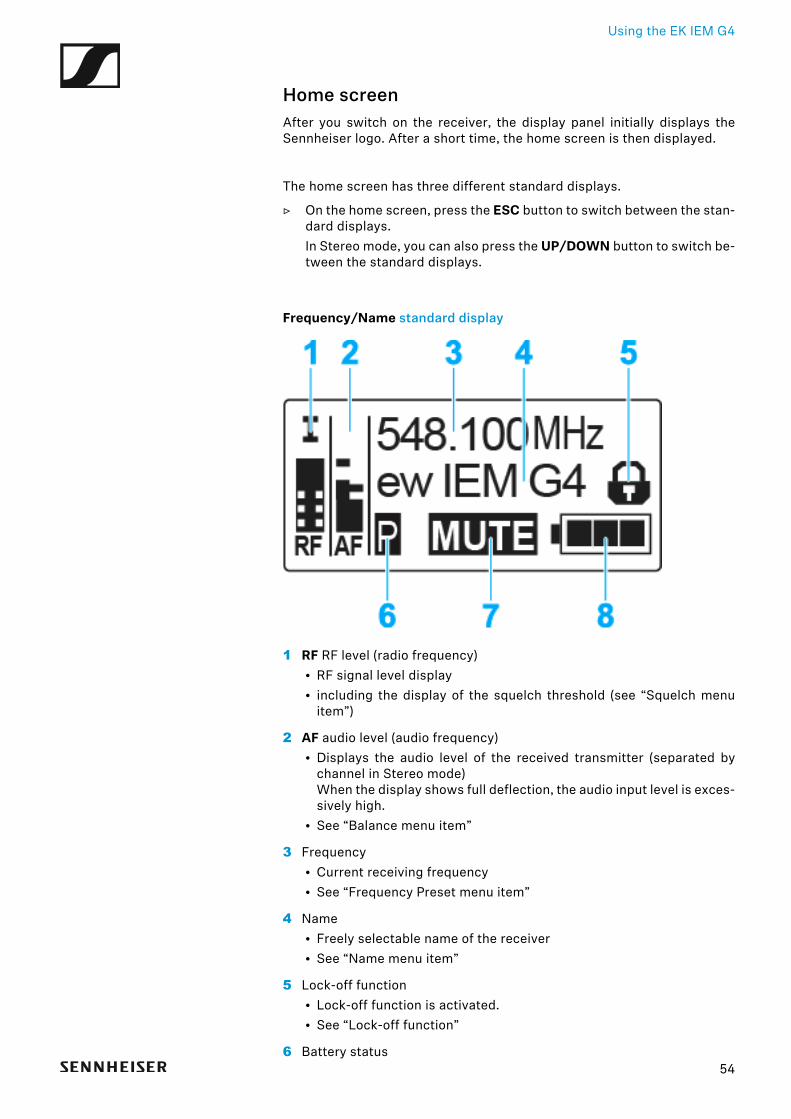
Frequency/Name standard display►
1 RF RF level (radio frequency)• RF signal level display• including the display of the squelch threshold (see “Squelch menu
item”)
2 AF audio level (audio frequency)• Displays the audio level of the received transmitter (separated by
channel in Stereo mode)When the display shows full deflection, the audio input level is exces-sively high.
• See “Balance menu item”
3 Frequency• Current receiving frequency• See “Frequency Preset menu item”
4 Name• Freely selectable name of the receiver• See “Name menu item”
5 Lock-off function• Lock-off function is activated.• See “Lock-off function”
6 Battery status
54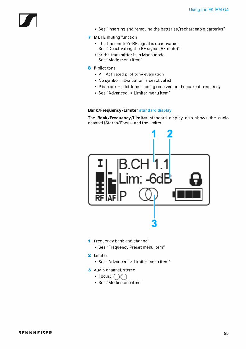
Using the EK IEM G4
• See “Inserting and removing the batteries/rechargeable batteries”
7 MUTE muting function• The transmitter’s RF signal is deactivated
See “Deactivating the RF signal (RF mute)”• or the transmitter is in Mono mode
See “Mode menu item”
8 P pilot tone• P = Activated pilot tone evaluation• No symbol = Evaluation is deactivated• P is black = pilot tone is being received on the current frequency• See “Advanced -> Limiter menu item”
Bank/Frequency/Limiter standard display
The Bank/Frequency/Limiter standard display also shows the audiochannel (Stereo/Focus) and the limiter.►
1 Frequency bank and channel• See “Frequency Preset menu item”
2 Limiter• See “Advanced -> Limiter menu item”
3 Audio channel, stereo• Focus: • See “Mode menu item”
55
Using the EK IEM G4
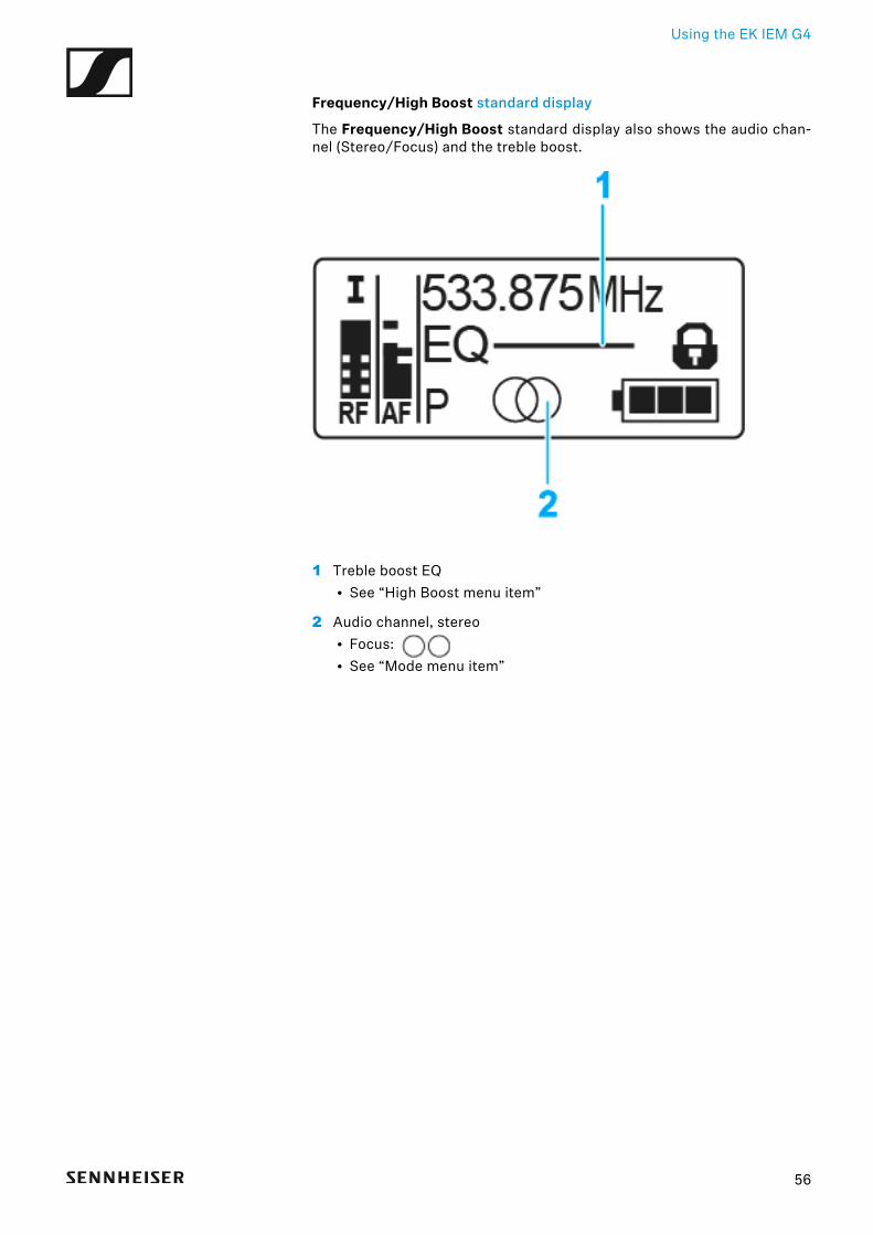
Frequency/High Boost standard display
The Frequency/High Boost standard display also shows the audio chan-nel (Stereo/Focus) and the treble boost.►
1 Treble boost EQ• See “High Boost menu item”
2 Audio channel, stereo• Focus: • See “Mode menu item”
56
Using the EK IEM G4
Setting options in the menuIn the EK IEM G4 menu, you can configure the following settings.
Adjusting the squelch threshold
▷ See “Squelch menu item”
Scanning for unused frequency presets, releases and selects frequen-cy presets
▷ See “Easy Setup menu item”
Setting the frequency bank and the channel
▷ See “Frequency Preset menu item”
Entering a freely selectable name
▷ See “Name menu item”
Adjusting the balance
▷ See “Balance menu item”
Adjusting Stereo or Focus mode
▷ See “Mode menu item”
Activating/deactivating the treble boost
▷ See “High Boost menu item”
Activating/deactivating automatic lock-off function
▷ See “Auto Lock menu item”
Configuring enhanced settings in the Advanced Menu:
• Setting the receiving frequencies for the frequency banks U1 to U6• Adjusting the limiter• Adjusting the volume boost• Adjusting the contrast of the display panel
57
Using the EK IEM G4
• Adjusting the menu item and loading profiles• Resetting the settings made in the operating menu• Displaying the current software revision▷ See “Advanced menu item”
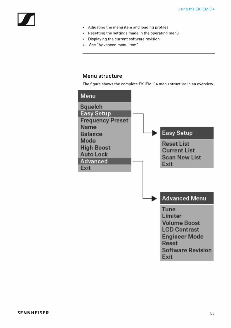
Menu structureThe figure shows the complete EK IEM G4 menu structure in an overview.►
58
Using the EK IEM G4
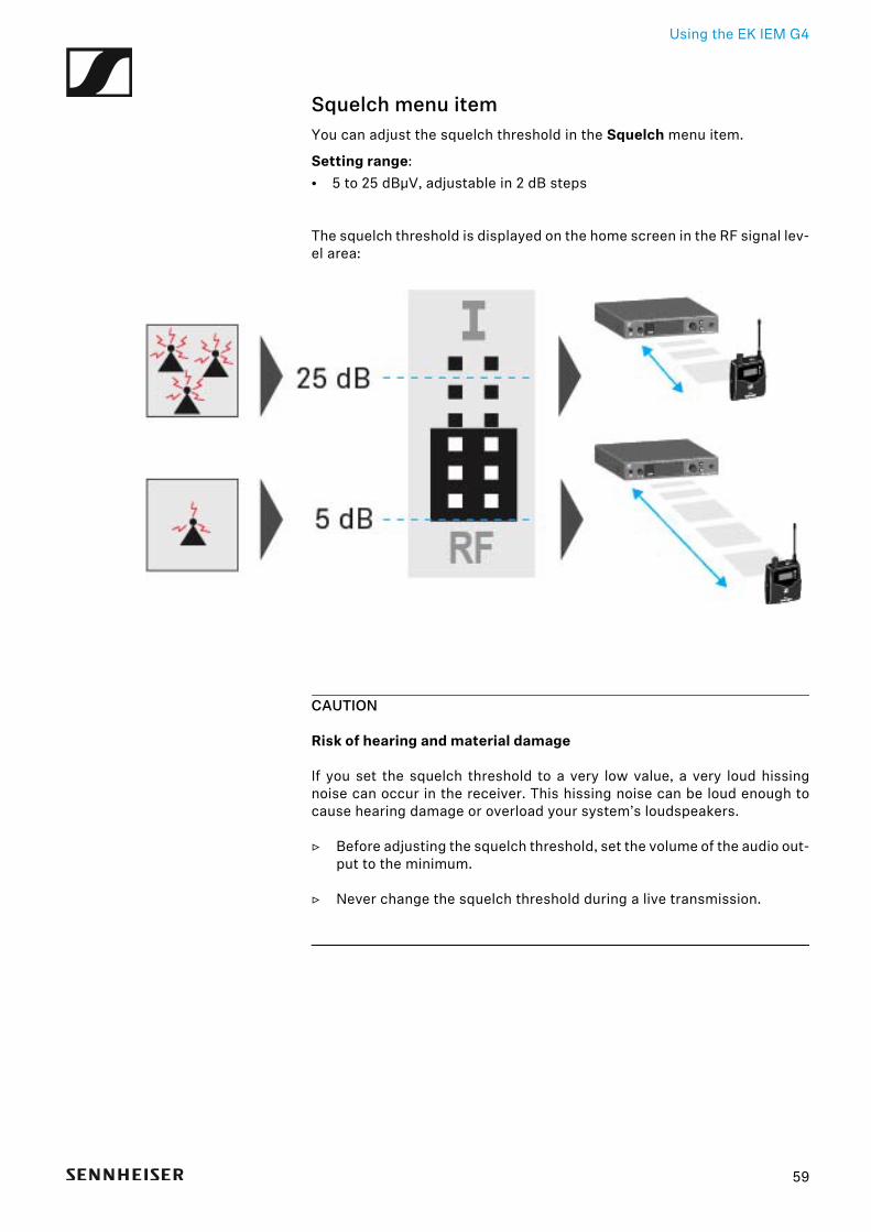
Squelch menu itemYou can adjust the squelch threshold in the Squelch menu item.
Setting range:• 5 to 25 dBμV, adjustable in 2 dB steps
The squelch threshold is displayed on the home screen in the RF signal lev-el area:
►
CAUTION
Risk of hearing and material damage
If you set the squelch threshold to a very low value, a very loud hissingnoise can occur in the receiver. This hissing noise can be loud enough tocause hearing damage or overload your system’s loudspeakers.
▷ Before adjusting the squelch threshold, set the volume of the audio out-put to the minimum.
▷ Never change the squelch threshold during a live transmission.
59
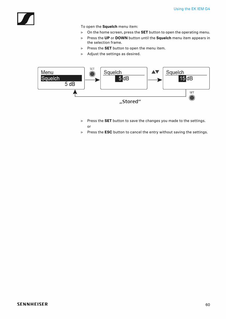
Using the EK IEM G4
To open the Squelch menu item:▷ On the home screen, press the SET button to open the operating menu.▷ Press the UP or DOWN button until the Squelch menu item appears in
the selection frame.▷ Press the SET button to open the menu item.▷ Adjust the settings as desired.
►
▷ Press the SET button to save the changes you made to the settings.or
▷ Press the ESC button to cancel the entry without saving the settings.
60
Using the EK IEM G4
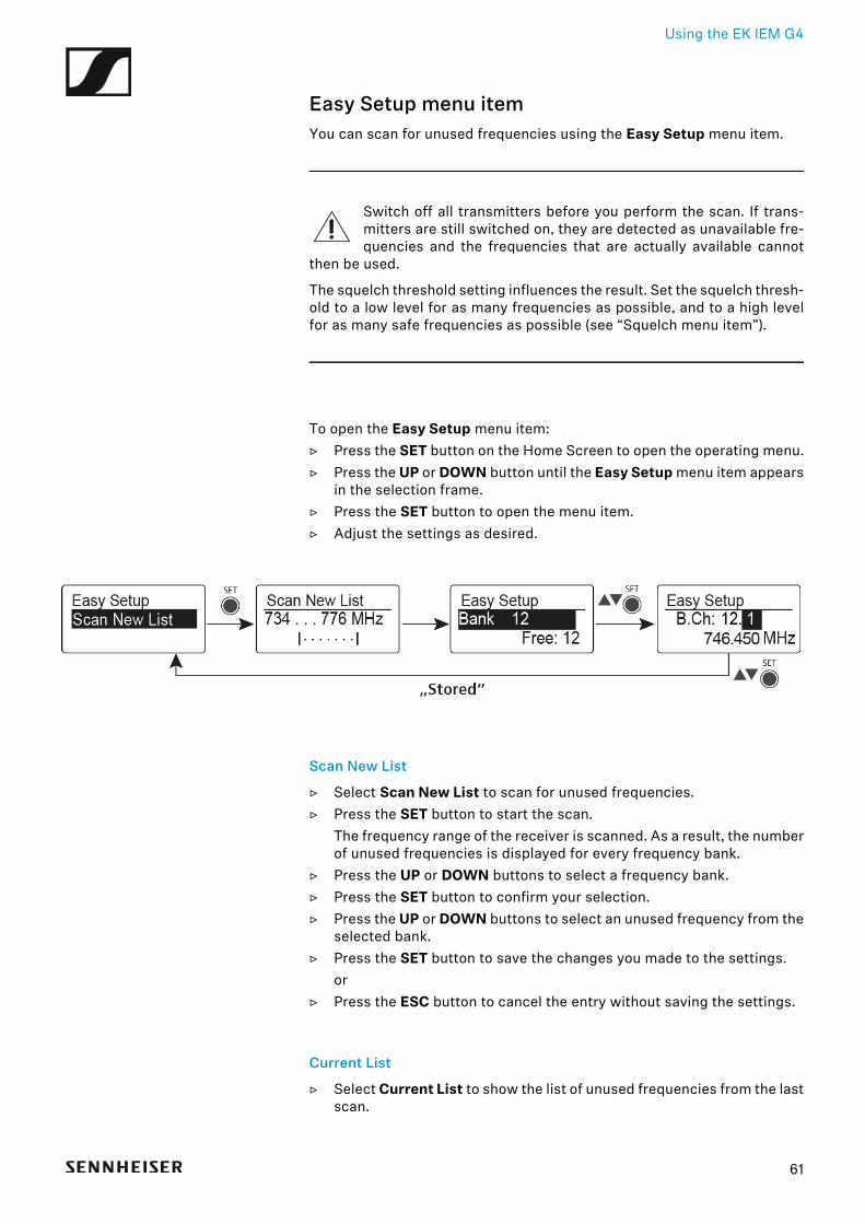
Easy Setup menu itemYou can scan for unused frequencies using the Easy Setup menu item.
Switch off all transmitters before you perform the scan. If trans-mitters are still switched on, they are detected as unavailable fre-quencies and the frequencies that are actually available cannot
then be used.
The squelch threshold setting influences the result. Set the squelch thresh-old to a low level for as many frequencies as possible, and to a high levelfor as many safe frequencies as possible (see “Squelch menu item”).
To open the Easy Setup menu item:▷ Press the SET button on the Home Screen to open the operating menu.▷ Press the UP or DOWN button until the Easy Setup menu item appears
in the selection frame.▷ Press the SET button to open the menu item.▷ Adjust the settings as desired.
►
Scan New List
▷ Select Scan New List to scan for unused frequencies.▷ Press the SET button to start the scan.
The frequency range of the receiver is scanned. As a result, the numberof unused frequencies is displayed for every frequency bank.
▷ Press the UP or DOWN buttons to select a frequency bank.▷ Press the SET button to confirm your selection.▷ Press the UP or DOWN buttons to select an unused frequency from the
selected bank.▷ Press the SET button to save the changes you made to the settings.
or▷ Press the ESC button to cancel the entry without saving the settings.
Current List
▷ Select Current List to show the list of unused frequencies from the lastscan.
61
Using the EK IEM G4
Reset
▷ Select Reset List to delete the list of unused frequencies.
Performing multi-channel frequency setup
As an alternative to the following procedure, multi-channel frequencysetup can also be performed using the Sennheiser Wireless Sys-tems Manager (WSM) software. For more information about con-
trolling devices via the Sennheiser Wireless Systems Manager (WSM)software, refer to the instruction manual for the software. You can down-load the software here:
www.sennheiser.com/wsm
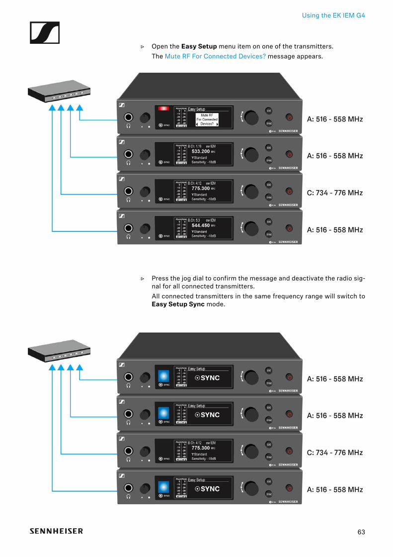
To perform the automatic frequency setup for multiple radio links simulta-neously:
▷ Connect all of the SR IEM G4 transmitters to one network using a net-work switch. See “Creating a data network”.The automatic frequency setup function only works for transmitters inthe same frequency range. Transmitters in a different frequency rangeare not included.
▷ Please note that all transmitters must be in the same IP address range.• The IP addresses can be automatically assigned if there is a DHCP
server in the network.• If there is no DHCP server in the network, the IP addresses must be
assigned manually. See “Advanced > IP Address menu item”.• Assign the IP addresses for all transmitters in the 192.168.x.x range
(the link-local range 169.254.x.x is also a possible alternative).
62
Using the EK IEM G4
▷ Open the Easy Setup menu item on one of the transmitters.The Mute RF For Connected Devices? message appears.
▷ Press the jog dial to confirm the message and deactivate the radio sig-nal for all connected transmitters.All connected transmitters in the same frequency range will switch toEasy Setup Sync mode.
63
Using the EK IEM G4
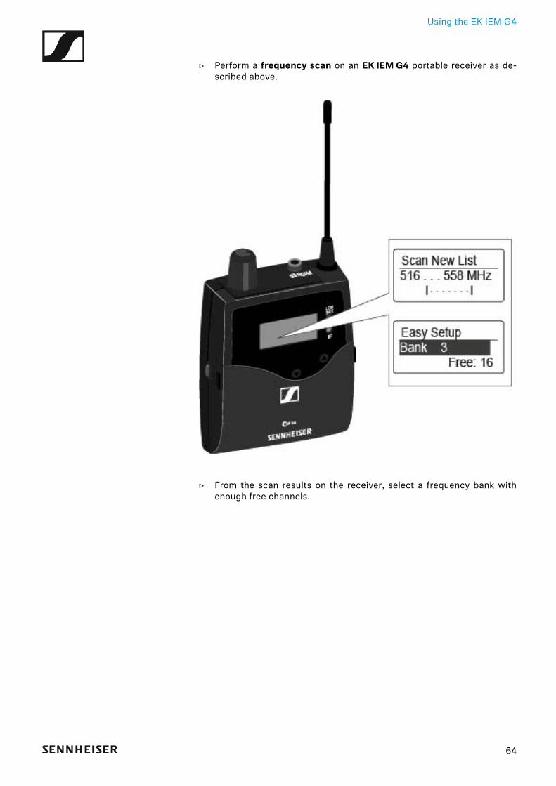
▷ Perform a frequency scan on an EK IEM G4 portable receiver as de-scribed above.
▷ From the scan results on the receiver, select a frequency bank withenough free channels.
64
Using the EK IEM G4
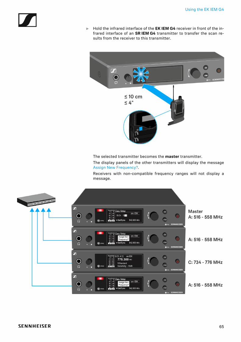
▷ Hold the infrared interface of the EK IEM G4 receiver in front of the in-frared interface of an SR IEM G4 transmitter to transfer the scan re-sults from the receiver to this transmitter.
The selected transmitter becomes the master transmitter.The display panels of the other transmitters will display the messageAssign New Frequency?.Receivers with non-compatible frequency ranges will not display amessage.
65
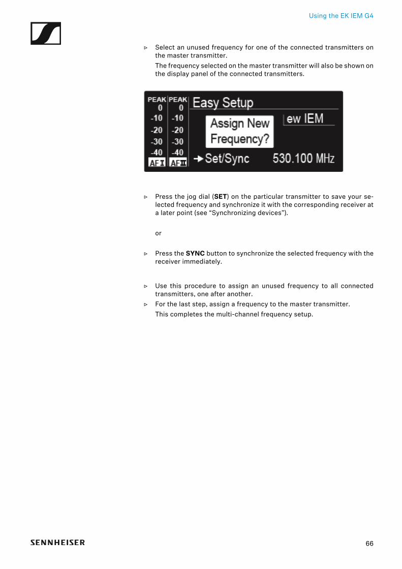
Using the EK IEM G4
▷ Select an unused frequency for one of the connected transmitters onthe master transmitter.The frequency selected on the master transmitter will also be shown onthe display panel of the connected transmitters.
▷ Press the jog dial (SET) on the particular transmitter to save your se-lected frequency and synchronize it with the corresponding receiver ata later point (see “Synchronizing devices”).
or
▷ Press the SYNC button to synchronize the selected frequency with thereceiver immediately.
▷ Use this procedure to assign an unused frequency to all connectedtransmitters, one after another.
▷ For the last step, assign a frequency to the master transmitter.This completes the multi-channel frequency setup.
66
Using the EK IEM G4
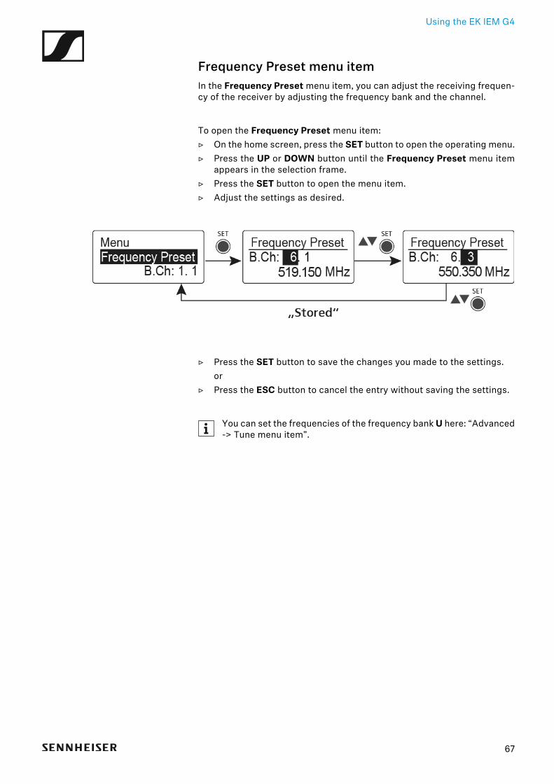
Frequency Preset menu itemIn the Frequency Preset menu item, you can adjust the receiving frequen-cy of the receiver by adjusting the frequency bank and the channel.
To open the Frequency Preset menu item:▷ On the home screen, press the SET button to open the operating menu.▷ Press the UP or DOWN button until the Frequency Preset menu item
appears in the selection frame.▷ Press the SET button to open the menu item.▷ Adjust the settings as desired.
►
▷ Press the SET button to save the changes you made to the settings.or
▷ Press the ESC button to cancel the entry without saving the settings.
You can set the frequencies of the frequency bank U here: “Advanced-> Tune menu item”.
67
Using the EK IEM G4
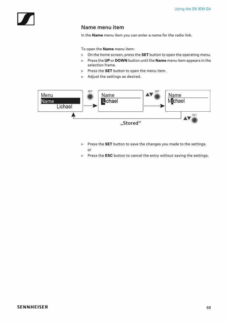
Name menu itemIn the Name menu item you can enter a name for the radio link.
To open the Name menu item:▷ On the home screen, press the SET button to open the operating menu.▷ Press the UP or DOWN button until the Name menu item appears in the
selection frame.▷ Press the SET button to open the menu item.▷ Adjust the settings as desired.
►
▷ Press the SET button to save the changes you made to the settings.or
▷ Press the ESC button to cancel the entry without saving the settings.
68
Using the EK IEM G4
Balance menu itemIn the Balance menu item you can adjust the balance of the audio chan-nels.
Setting range:• 31 steps: L = R, L1 to L15 and R1 to R15
To open the Balance menu item:▷ On the home screen, press the SET button to open the operating menu.▷ Press the UP or DOWN button until the Balance menu item appears in
the selection frame.▷ Press the SET button to open the menu item.▷ Adjust the settings as desired.
►
▷ Press the SET button to save the changes you made to the settings.or
▷ Press the ESC button to cancel the entry without saving the settings.
69
Using the EK IEM G4
Mode menu itemIn the Mode menu item you can switch between Stereo and Focus.
Stereo mode
The left-right signals are available as usual.
The Balance setting serves to adjust the balance between the left and rightstereo signal. See “Balance menu item”.
▷ To use it, activate Stereo mode on the corresponding SR IEM G4 trans-mitter. See “Mode menu item”.
Focus mode
The corresponding SR IEM G4 transmitter operates in Stereo mode.
• The left-right signals are mixed and are available as a mono signal inboth headphone channels.
• The balance setting serves to adjust the relative levels of the two sepa-rate channels in the mixed mono signal. See “Balance menu item”.
The corresponding SR IEM G4 transmitter operates in Mono mode.
• Only the left audio input of the SR IEM G4 is received as a mono signal.
To open the Mode menu item:▷ On the home screen, press the SET button to open the operating menu.▷ Press the UP or DOWN button until the Mode menu item appears in the
selection frame.▷ Press the SET button to open the menu item.▷ Adjust the settings as desired.
►
▷ Press the SET button to save the changes you made to the settings.or
▷ Press the ESC button to cancel the entry without saving the settings.
70
Using the EK IEM G4
High Boost menu itemIn the High Boost menu item you can change the treble boost of the outputsignal.
Setting range:• 8 dB at 10 kHz
To open the High Boost menu item:▷ On the home screen, press the SET button to open the operating menu.▷ Press the UP or DOWN button until the High Boost menu item appears
in the selection frame.▷ Press the SET button to open the menu item.▷ Adjust the settings as desired.
►
▷ Press the SET button to save the changes you made to the settings.or
▷ Press the ESC button to cancel the entry without saving the settings.
71
Using the EK IEM G4
Auto Lock menu itemIn the Auto Lock menu item you can activate or deactivate the auto lock-off function.
You can find information about temporarily deactivating the lock-offfunction during operation under “Lock-off function”.
To open the Auto Lock menu item:▷ On the home screen, press the SET button to open the operating menu.▷ Press the UP or DOWN button until the Auto Lock menu item appears
in the selection frame.▷ Press the SET button to open the menu item.▷ Adjust the settings as desired.
►
▷ Press the SET button to save the changes you made to the settings.or
▷ Press the ESC button to cancel the entry without saving the settings.
72
Using the EK IEM G4
Advanced menu itemIn the Advanced submenu you can configure enhanced settings.
To open the Advanced submenu:▷ On the home screen, press the SET button to open the operating menu.▷ Press the UP or DOWN button until the Advanced menu item appears
in the selection frame.▷ Press the SET button to open the menu item.
The following sub-items are available:
Adjusting the receiving frequency for the frequency bank U
▷ See “Advanced -> Tune menu item”
Adjusting the limiter
▷ See “Advanced -> Limiter menu item”
Adjusting the volume boost
▷ See “Advanced -> Volume Boost menu item”
Adjusting the contrast of the display panel
▷ See “Advanced -> LCD Contrast menu item”
Adjusting the menu item and loading profiles
▷ See “Advanced -> Engineer Mode menu item”
Resetting the receiver
▷ See “Advanced -> Reset menu item”
Displaying the current software revision
▷ See “Advanced -> Software Revision menu item”
73
Using the EK IEM G4
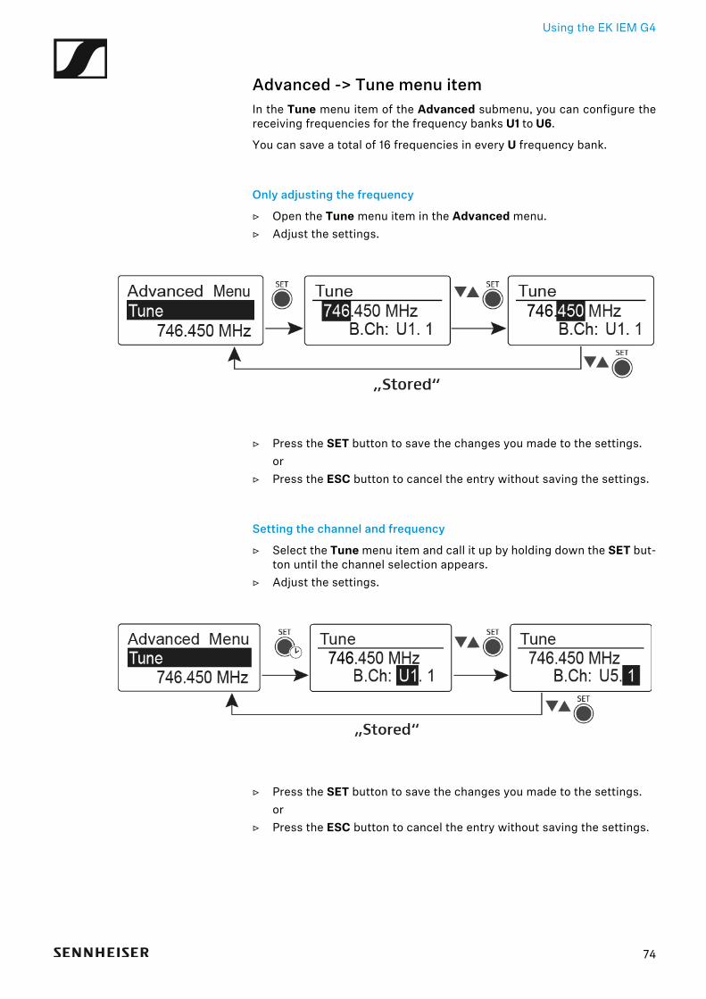
Advanced -> Tune menu itemIn the Tune menu item of the Advanced submenu, you can configure thereceiving frequencies for the frequency banks U1 to U6.
You can save a total of 16 frequencies in every U frequency bank.
Only adjusting the frequency
▷ Open the Tune menu item in the Advanced menu.▷ Adjust the settings.
►
▷ Press the SET button to save the changes you made to the settings.or
▷ Press the ESC button to cancel the entry without saving the settings.
Setting the channel and frequency
▷ Select the Tune menu item and call it up by holding down the SET but-ton until the channel selection appears.
▷ Adjust the settings.
►
▷ Press the SET button to save the changes you made to the settings.or
▷ Press the ESC button to cancel the entry without saving the settings.
74
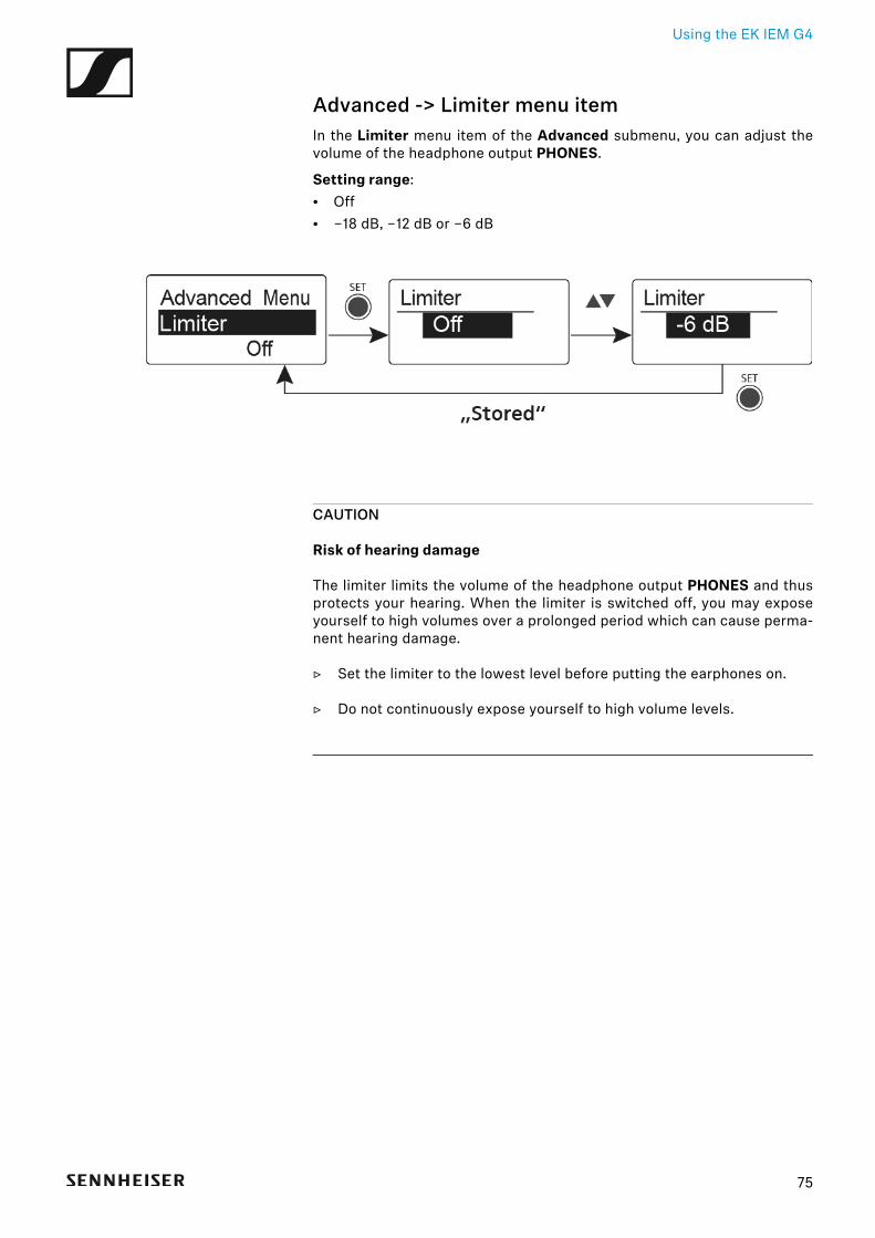
Using the EK IEM G4
Advanced -> Limiter menu itemIn the Limiter menu item of the Advanced submenu, you can adjust thevolume of the headphone output PHONES.
Setting range:• Off• −18 dB, −12 dB or −6 dB
►
CAUTION
Risk of hearing damage
The limiter limits the volume of the headphone output PHONES and thusprotects your hearing. When the limiter is switched off, you may exposeyourself to high volumes over a prolonged period which can cause perma-nent hearing damage.
▷ Set the limiter to the lowest level before putting the earphones on.
▷ Do not continuously expose yourself to high volume levels.
75
Using the EK IEM G4
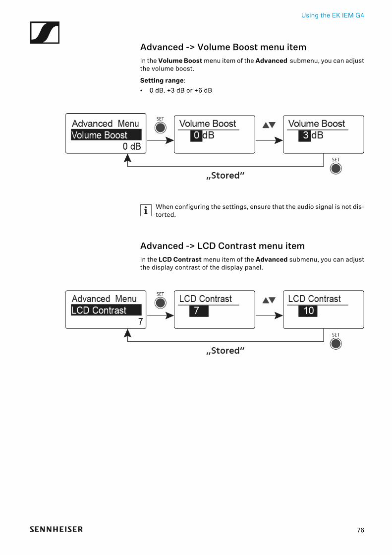
Advanced -> Volume Boost menu itemIn the Volume Boost menu item of the Advanced submenu, you can adjustthe volume boost.
Setting range:• 0 dB, +3 dB or +6 dB
►
When configuring the settings, ensure that the audio signal is not dis-torted.
Advanced -> LCD Contrast menu itemIn the LCD Contrast menu item of the Advanced submenu, you can adjustthe display contrast of the display panel.
►
76
Using the EK IEM G4
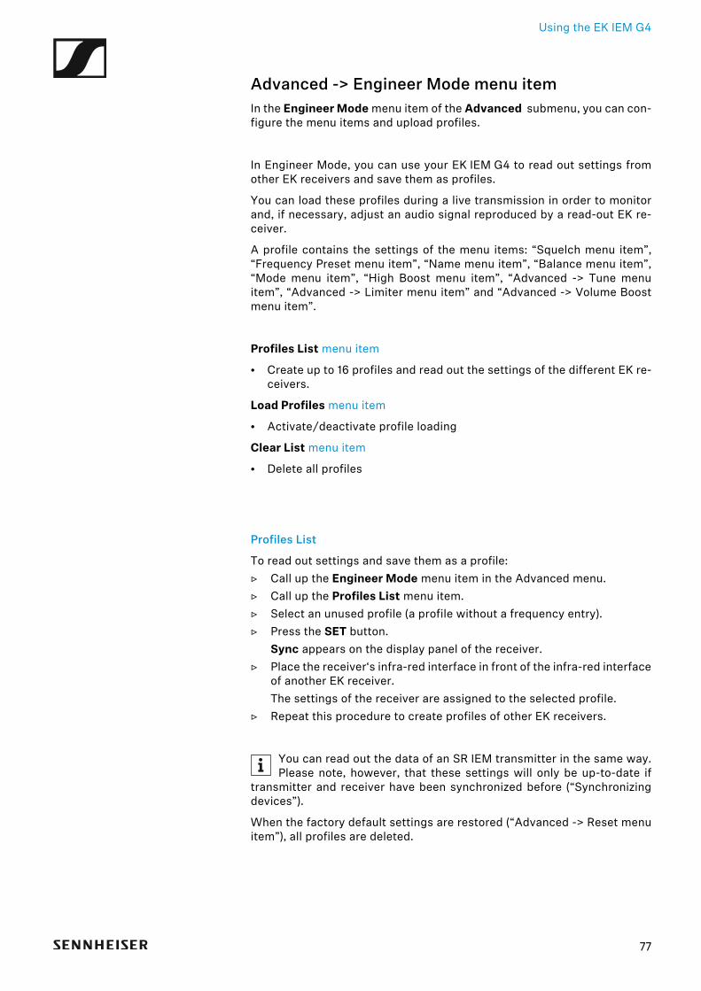
Advanced -> Engineer Mode menu itemIn the Engineer Mode menu item of the Advanced submenu, you can con-figure the menu items and upload profiles.
In Engineer Mode, you can use your EK IEM G4 to read out settings fromother EK receivers and save them as profiles.
You can load these profiles during a live transmission in order to monitorand, if necessary, adjust an audio signal reproduced by a read-out EK re-ceiver.
A profile contains the settings of the menu items: “Squelch menu item”,“Frequency Preset menu item”, “Name menu item”, “Balance menu item”,“Mode menu item”, “High Boost menu item”, “Advanced -> Tune menuitem”, “Advanced -> Limiter menu item” and “Advanced -> Volume Boostmenu item”.
Profiles List menu item
• Create up to 16 profiles and read out the settings of the different EK re-ceivers.
Load Profiles menu item
• Activate/deactivate profile loading
Clear List menu item
• Delete all profiles
Profiles List
To read out settings and save them as a profile:▷ Call up the Engineer Mode menu item in the Advanced menu.▷ Call up the Profiles List menu item.▷ Select an unused profile (a profile without a frequency entry).▷ Press the SET button.
Sync appears on the display panel of the receiver.▷ Place the receiver‘s infra-red interface in front of the infra-red interface
of another EK receiver.The settings of the receiver are assigned to the selected profile.
▷ Repeat this procedure to create profiles of other EK receivers.
You can read out the data of an SR IEM transmitter in the same way.Please note, however, that these settings will only be up-to-date if
transmitter and receiver have been synchronized before (“Synchronizingdevices”).
When the factory default settings are restored (“Advanced -> Reset menuitem”), all profiles are deleted.
77
Using the EK IEM G4
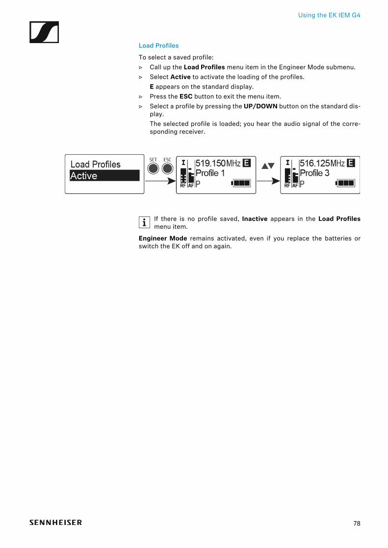
Load Profiles
To select a saved profile:▷ Call up the Load Profiles menu item in the Engineer Mode submenu.▷ Select Active to activate the loading of the profiles.
E appears on the standard display.▷ Press the ESC button to exit the menu item.▷ Select a profile by pressing the UP/DOWN button on the standard dis-
play.The selected profile is loaded; you hear the audio signal of the corre-sponding receiver.
►
If there is no profile saved, Inactive appears in the Load Profilesmenu item.
Engineer Mode remains activated, even if you replace the batteries orswitch the EK off and on again.
78
Using the EK IEM G4
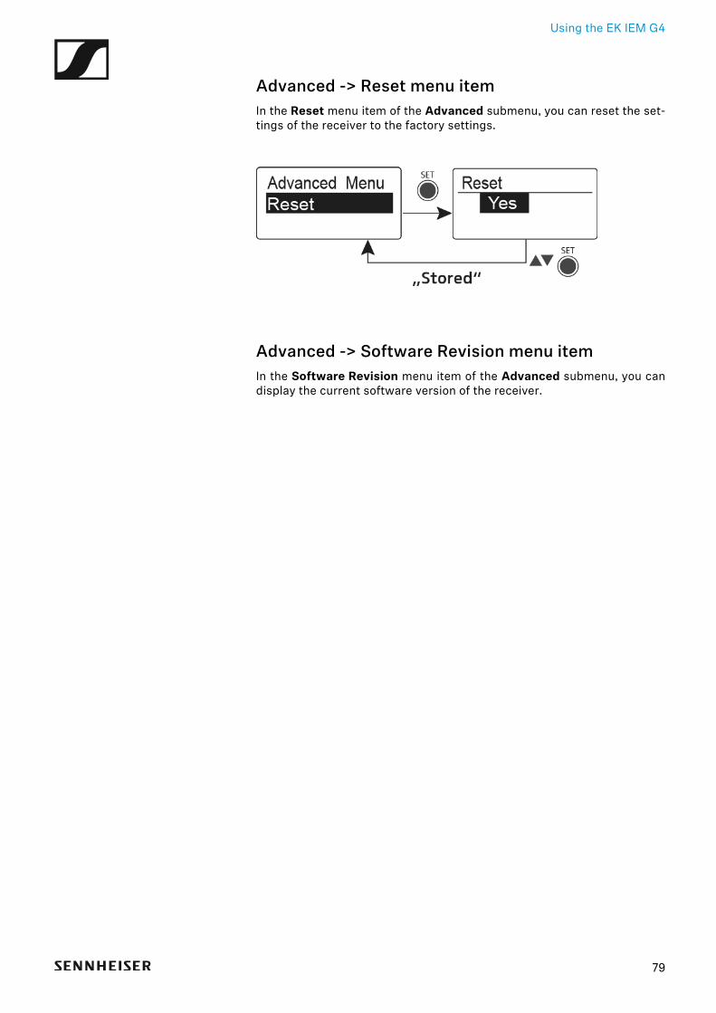
Advanced -> Reset menu itemIn the Reset menu item of the Advanced submenu, you can reset the set-tings of the receiver to the factory settings.
►
Advanced -> Software Revision menu itemIn the Software Revision menu item of the Advanced submenu, you candisplay the current software version of the receiver.
79

Using the SR IEM G4
Using the SR IEM G4These sections contain detailed information about using the SR IEM G4.
You can find information on installation and startup of the SR IEM G4 under“Installing the SR IEM G4”.
80
Using the SR IEM G4
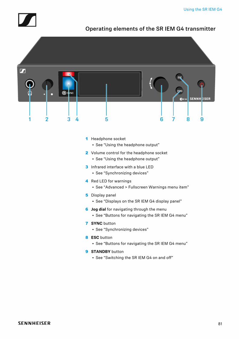
Operating elements of the SR IEM G4 transmitter►
1 Headphone socket• See “Using the headphone output”
2 Volume control for the headphone socket• See “Using the headphone output”
3 Infrared interface with a blue LED• See “Synchronizing devices”
4 Red LED for warnings• See “Advanced > Fullscreen Warnings menu item”
5 Display panel• See “Displays on the SR IEM G4 display panel”
6 Jog dial for navigating through the menu• See “Buttons for navigating the SR IEM G4 menu”
7 SYNC button• See “Synchronizing devices”
8 ESC button• See “Buttons for navigating the SR IEM G4 menu”
9 STANDBY button• See “Switching the SR IEM G4 on and off”
81
Using the SR IEM G4
Switching the SR IEM G4 on and offTo switch on the transmitter:▷ Short-press the STANDBY button.
The transmitter switches on and the standard display appears.
To switch the transmitter to standby mode:▷ If necessary, deactivate the lock-off function (see “Lock-off function”).▷ Press and hold the STANDBY button until OFF appears on the display
panel.The display panel switches off.
To completely switch the transmitter off:▷ Disconnect the transmitter from the power supply system by unplug-
ging the power supply unit from the wall socket.
82
Using the SR IEM G4
Using the headphone outputYou can use the headphone output on the front of the SR IEM G4 (6.3 mmjack) to listen to the audio signal.
ATTENTION
Danger due to high volume levels
Volume levels that are too high may damage your hearing.
▷ Turn down the volume of the headphone output before you put on theheadphone.
▷ Connect the headphone to the headphone socket.▷ Control the volume by turning the volume control next to the head-
phone socket.
83
Using the SR IEM G4
Configuring the audio channels (mono/stereo)You can configure audio channels in the “Mode menu item”. You can selecteither Stereo or Mono:
▷ Select Stereo when you want to send a separate audio signal on chan-nel I and channel II (e.g. channel I = audio signal of the moderator/mu-sician, channel II = sum of all audio signals).The moderator/musician then has the option to adjust the volume dis-tribution on his or her receiver as needed.
In Stereo mode, you can receive the two input signals either as amixed mono signal or as a stereo signal. To do so, you must select Fo-cus or Stereo mode on the EK IEM G4 receiver. See “Mode menu
item”. ►
▷ Select Mono when you only want to transmit one channel. The signal ofthe left audio input BAL AF IN L is used.
►
In Mono mode, you have to deactivate the pilot tone evaluation onyour EK IEM G4 receiver. This is the only way to ensure that your re-
ceivers will transmit the same signal on channel I and channel II.
84
Using the SR IEM G4
Deactivating the RF signal (RF mute)
To deactivate the RF signal:▷ Press the STANDBY button.
RF Mute Off? appears in the display panel.▷ Turn the jog dial.
RF Mute ON? appears in the display panel.▷ Press the jog dial.
The transmission frequency is displayed, however the transmitter isnot transmitting an RF signal. The RF Mute warning appears (see “Dis-plays on the SR IEM G4 display panel”) and the LED warnings are illu-minated (see “Operating elements of the SR IEM G4 transmitter”).
To activate the RF signal:▷ Press the STANDBY button.
RF Mute Off? appears in the display panel.▷ Turn the jog dial.
RF Mute ON? appears in the display panel.▷ Press the jog dial.
The warning in the display and the LED warnings go out.
85
Using the SR IEM G4
Lock-off functionYou can set the automatic lock-off function in the Auto lock menu (see“Auto Lock menu item”).
When you have switched on the lock-off function, you will have to turn thetransmitter off and on again in order to operate it.
To temporarily deactivate the lock-off function:▷ Press the jog dial.
Locked appears in the display panel.▷ Turn the jog dial.
Unlock? appears in the display panel.▷ Press the jog dial.
Lock-off function is now temporarily deactivated.
When you are in the operating menu
>> Lock-off function is deactivated long enough for you to work in the op-erating menu.
You are in the standard display
>> Lock-off function is automatically activated after 10 seconds.
The Lock-off function icon flashes while the lock-off function is being acti-vated again.
86
Using the SR IEM G4
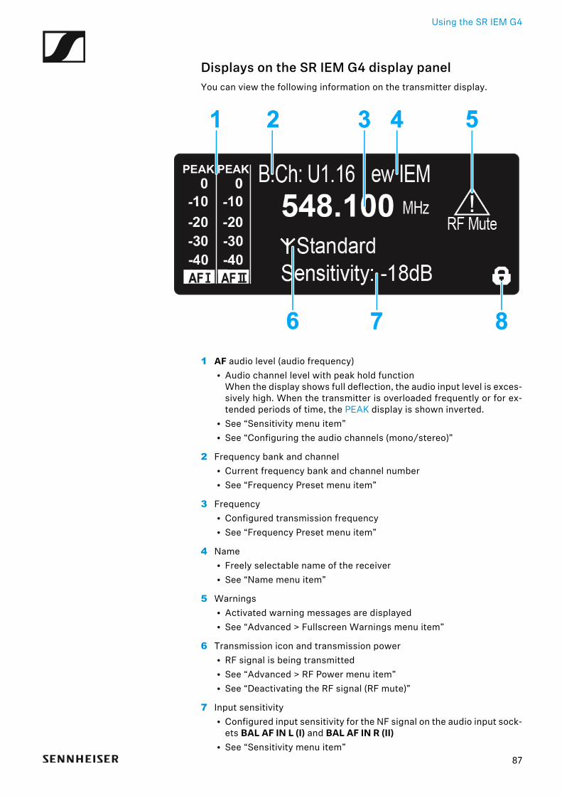
Displays on the SR IEM G4 display panelYou can view the following information on the transmitter display.
1 AF audio level (audio frequency)• Audio channel level with peak hold function
When the display shows full deflection, the audio input level is exces-sively high. When the transmitter is overloaded frequently or for ex-tended periods of time, the PEAK display is shown inverted.
• See “Sensitivity menu item”• See “Configuring the audio channels (mono/stereo)”
2 Frequency bank and channel• Current frequency bank and channel number• See “Frequency Preset menu item”
3 Frequency• Configured transmission frequency• See “Frequency Preset menu item”
4 Name• Freely selectable name of the receiver• See “Name menu item”
5 Warnings• Activated warning messages are displayed• See “Advanced > Fullscreen Warnings menu item”
6 Transmission icon and transmission power• RF signal is being transmitted• See “Advanced > RF Power menu item”• See “Deactivating the RF signal (RF mute)”
7 Input sensitivity• Configured input sensitivity for the NF signal on the audio input sock-
ets BAL AF IN L (I) and BAL AF IN R (II)• See “Sensitivity menu item”
87
Using the SR IEM G4
8 Lock-off function• Lock-off function is activated.• See “Auto Lock menu item”
>> “Buttons for navigating the SR IEM G4 menu”
>> “Setting options in the menu”
►
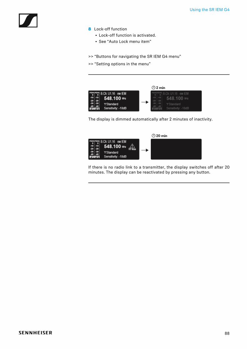
The display is dimmed automatically after 2 minutes of inactivity.
►
If there is no radio link to a transmitter, the display switches off after 20minutes. The display can be reactivated by pressing any button.
88
Using the SR IEM G4
Buttons for navigating the SR IEM G4 menu
Navigating through the menu
To open the menu:▷ Press the jog dial.
The operating menu is shown on the transmitter display panel.
To open a menu item:▷ Turn the jog dial to navigate through the individual menu items.▷ Press the jog dial to open the selected menu item.
“Operating elements of the SR IEM G4 transmitter”
Making changes in a menu item
After you open a menu item, you can make changes as follows:
▷ Turn the jog dial to set the displayed value.▷ Press the jog dial to save your setting.▷ Press the ESC button to leave the menu item without saving the set-
ting.
“Operating elements of the SR IEM G4 transmitter”
>> “Displays on the SR IEM G4 display panel”
>> “Setting options in the menu”
89
Using the SR IEM G4
Setting options in the menuIn the SR IEM G4 menu, you can configure the following settings.
Adjusting the input sensitivity
▷ See “Sensitivity menu item”
Configuring the audio transmission mode (mono/stereo)
▷ See “Mode menu item”
Activating Easy Setup Sync
▷ See “Easy Setup menu item”
Setting the frequency bank and the channel
▷ See “Frequency Preset menu item”
Entering a freely selectable name
▷ See “Name menu item”
Activating/deactivating the automatic lock-off function
▷ See “Auto Lock menu item”
Configuring enhanced settings in the Advanced Menu:
• Adjusting the transmission frequencies for the U frequency bank• Adjusting the parameters for transmission to the receivers• Configuring the transmission power• Adjusting the warnings• Adjusting the contrast of the display panel• Resetting the transmitter• Configuring the IP address• Displaying the current software revision▷ See “Advanced menu item”
90
Using the SR IEM G4
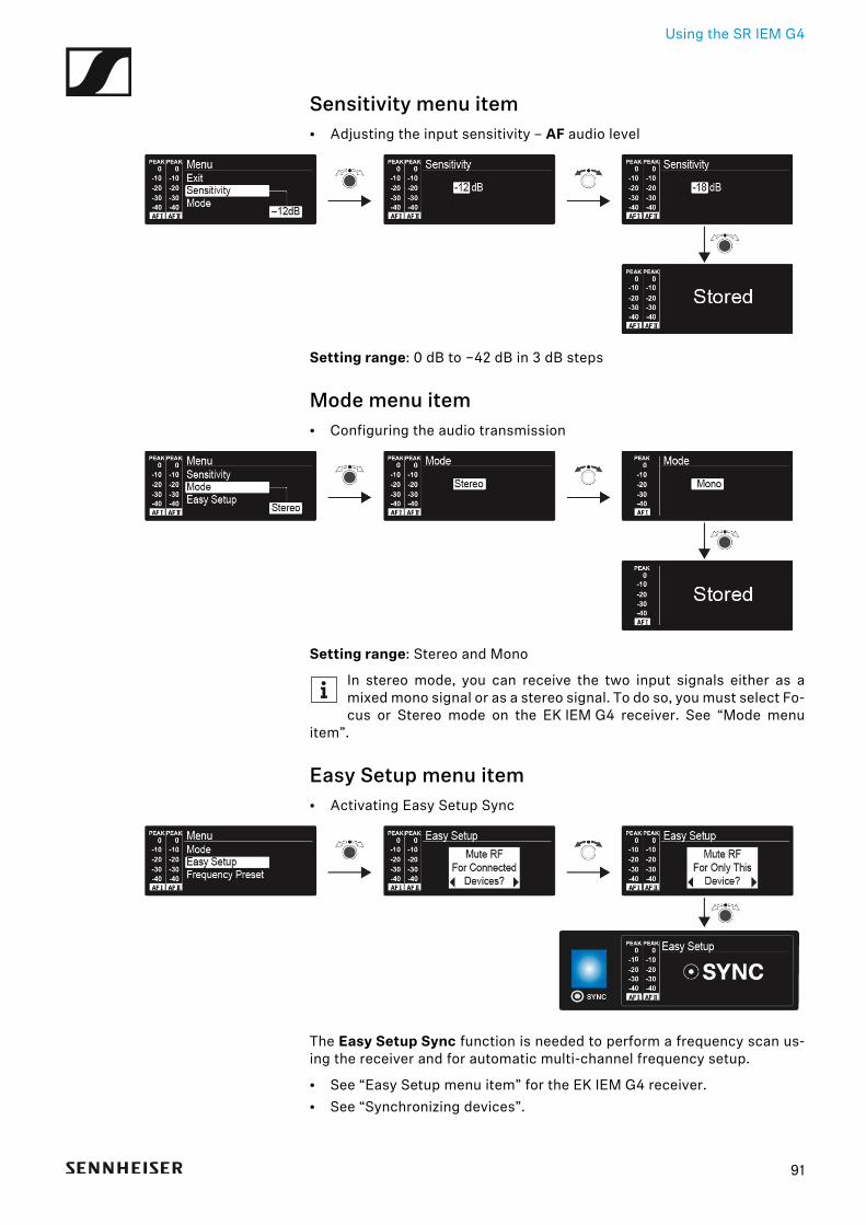
Sensitivity menu item• Adjusting the input sensitivity – AF audio level►
Setting range: 0 dB to −42 dB in 3 dB steps
Mode menu item• Configuring the audio transmission►
Setting range: Stereo and Mono
In stereo mode, you can receive the two input signals either as amixed mono signal or as a stereo signal. To do so, you must select Fo-cus or Stereo mode on the EK IEM G4 receiver. See “Mode menu
item”.
Easy Setup menu item• Activating Easy Setup Sync►
The Easy Setup Sync function is needed to perform a frequency scan us-ing the receiver and for automatic multi-channel frequency setup.
• See “Easy Setup menu item” for the EK IEM G4 receiver.• See “Synchronizing devices”.
91
Using the SR IEM G4
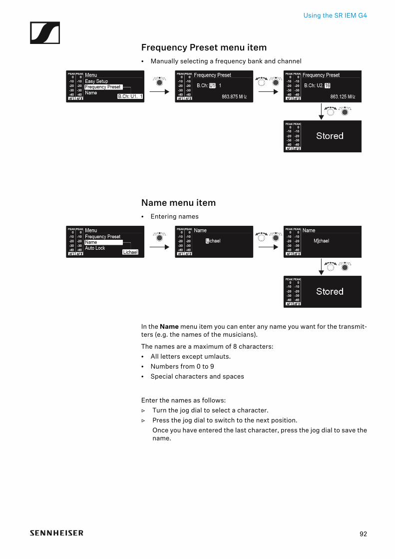
Frequency Preset menu item• Manually selecting a frequency bank and channel►
Name menu item• Entering names►
In the Name menu item you can enter any name you want for the transmit-ters (e.g. the names of the musicians).
The names are a maximum of 8 characters:• All letters except umlauts.• Numbers from 0 to 9• Special characters and spaces
Enter the names as follows:▷ Turn the jog dial to select a character.▷ Press the jog dial to switch to the next position.
Once you have entered the last character, press the jog dial to save thename.
92
Using the SR IEM G4
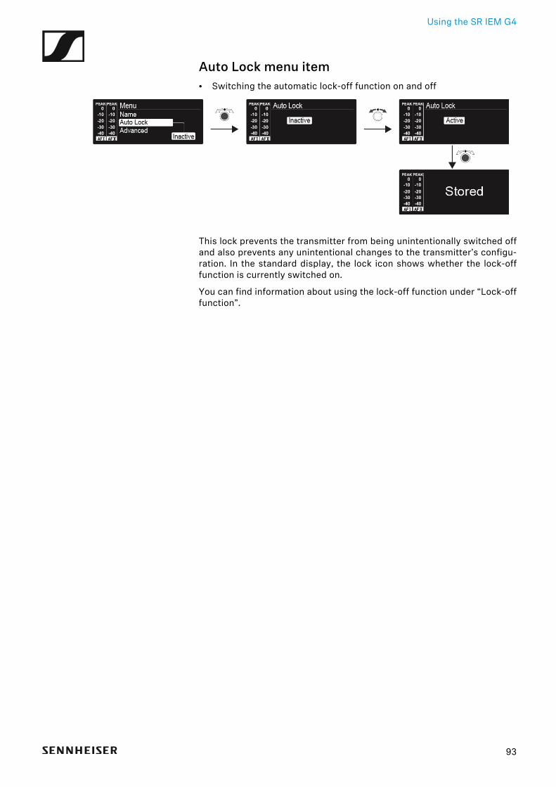
Auto Lock menu item• Switching the automatic lock-off function on and off►
This lock prevents the transmitter from being unintentionally switched offand also prevents any unintentional changes to the transmitter’s configu-ration. In the standard display, the lock icon shows whether the lock-offfunction is currently switched on.
You can find information about using the lock-off function under “Lock-offfunction”.
93
Using the SR IEM G4
Advanced menu itemIn the Advanced submenu you can configure enhanced settings.
The following sub-items are available:
Adjusting the transmission frequencies for the U frequency bank
▷ See “Advanced > Tune menu item”
Adjusting the parameters for transmission to the receivers
▷ See “Advanced > Sync Settings menu item”
Configuring the transmission power
▷ See “Advanced > RF Power menu item”
Adjusting the warnings
▷ See “Advanced > Fullscreen Warnings menu item”
Adjusting the contrast of the display panel
▷ See “Advanced > Brightness menu item”
Resetting the transmitter
▷ See “Advanced > Reset menu item”
Configuring the IP address
▷ See “Advanced > IP Address menu item”
Displaying the current software revision
▷ See “Advanced > Software Revision menu item”
94
Using the SR IEM G4
Advanced > Tune menu item• Configuring transmission frequencies and frequency banks U1 to U6
You can save a total of 16 channels in the frequency banks U1 to U6.
Only adjusting the frequency
▷ Open the Tune menu item in the Advanced menu.▷ Adjust the settings.►
Setting the channel and frequency
▷ Select the Tune menu item and call it up by holding down the jog dialuntil the channel selection appears.
▷ Adjust the settings.►
95
Using the SR IEM G4
Advanced > Sync Settings menu item• Configuring, activating or deactivating parameters for transmission to
the receivers►
When the check box is activated, the value will be transmitted during syn-chronization. If it is deactivated, the value will not be transmitted.
You can configure and activate/deactivate the following parameters:• Balance• Squelch• Mode• High Boost• Auto Lock• Limiter
See “Synchronizing devices”.
Advanced > RF Power menu item• Configuring the transmission power►
You can configure the transmission power in three steps in the RF Powermenu item. Please note the information at the following address:
General conditions and restrictions for the use of frequencies
Setting range:
• Low: 10 mW• Standard: 30 mW• High: 50 mW
If you are using the AC 41 antenna combiner, the transmission pow-er of the connected transmitters cannot be set to more than 30 mW(default) for legal reasons.
96
Using the SR IEM G4
Advanced > Fullscreen Warnings menu item• Activating/deactivating warnings►
You can activate or deactivate the following warnings:
AF Peak
• The audio level is too high.
RF Mute
• The RF signal from the transmitter to the receiver is deactivated.
Advanced > Brightness menu item• Adjusting the contrast of the display panel►
You can configure the contrast of the display in 16 steps.
Setting range: 0 to 15
97
Using the SR IEM G4
Advanced > Reset menu item• Resetting the transmitter►
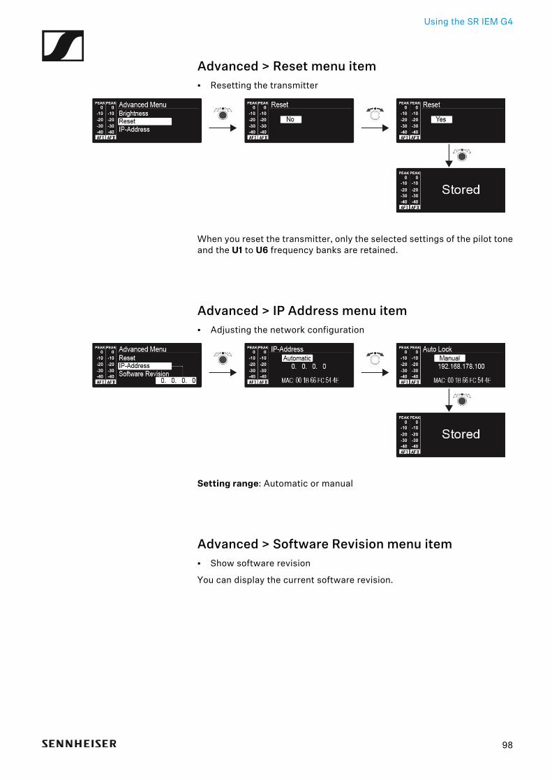
When you reset the transmitter, only the selected settings of the pilot toneand the U1 to U6 frequency banks are retained.
Advanced > IP Address menu item• Adjusting the network configuration►
Setting range: Automatic or manual
Advanced > Software Revision menu item• Show software revision
You can display the current software revision.
98
Establishing a radio link
99
Establishing a radio linkTo establish a radio link between the transmitter and receiver, the samefrequency must be set in both devices.
You can do this in a number of different ways:
1. Use the Easy Setup function to perform an automatic frequency set-up (see “Easy Setup menu item”).
2. Set a frequency in the receiver manually (see “Frequency Preset menuitem”) and synchronize it with the transmitter (see “Synchronizing de-vices”).
3. Set the frequency on the receiver and the transmitter manually(EK IEM G4: “Frequency Preset menu item”, SR IEM G4: “FrequencyPreset menu item”).
Setting notes
Please note the following when synchronizing a transmitter with a receiv-ers:
▷ Only use transmitters and receivers from the same frequency range(see the type plate on the transmitter and receiver).
▷ Make sure that your chosen frequencies are listed in the frequency ta-ble for the particular frequency range (see “Frequency tables”).
▷ Ensure that the desired frequencies are permitted in your country andapply for an operating license if necessary.
Please note the information at the following address:
General conditions and restrictions for the use of frequencies
Synchronizing devices
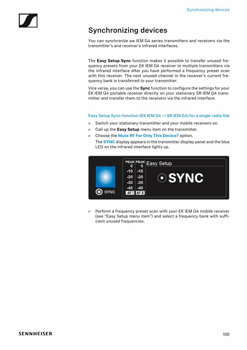
Synchronizing devicesYou can synchronize ew IEM G4 series transmitters and receivers via thetransmitter’s and receiver’s infrared interfaces.
The Easy Setup Sync function makes it possible to transfer unused fre-quency presets from your EK IEM G4 receiver to multiple transmitters viathe infrared interface after you have performed a frequency preset scanwith this receiver. The next unused channel in the receiver’s current fre-quency bank is transferred to your transmitter.
Vice versa, you can use the Sync function to configure the settings for yourEK IEM G4 portable receiver directly on your stationary SR IEM G4 trans-mitter and transfer them to the receivers via the infrared interface.
Easy Setup Sync-function (EK IEM G4 -> SR IEM G4) for a single radio link
▷ Switch your stationary transmitter and your mobile receivers on.▷ Call up the Easy Setup menu item on the transmitter.▷ Choose the Mute RF For Only This Device? option.
The SYNC display appears in the transmitter display panel and the blueLED on the infrared interface lights up.
▷ Perform a frequency preset scan with your EK IEM G4 mobile receiver(see “Easy Setup menu item”) and select a frequency bank with suffi-cient unused frequencies.
100
Synchronizing devices
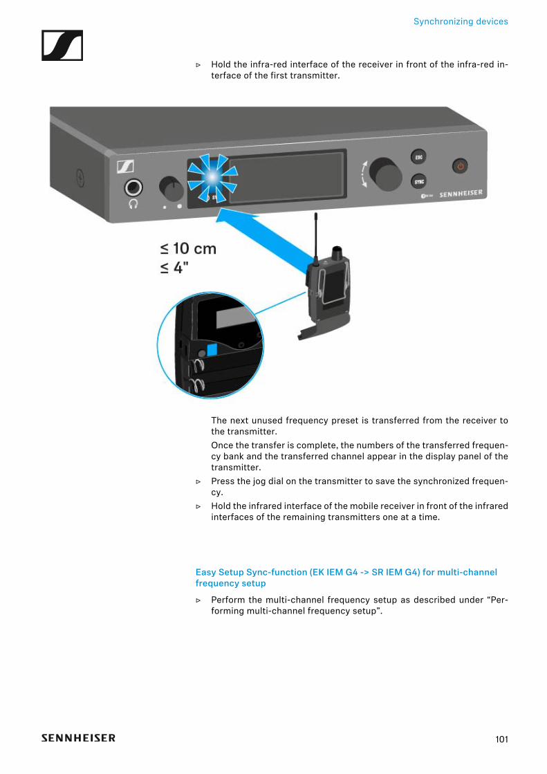
▷ Hold the infra-red interface of the receiver in front of the infra-red in-terface of the first transmitter.
The next unused frequency preset is transferred from the receiver tothe transmitter.Once the transfer is complete, the numbers of the transferred frequen-cy bank and the transferred channel appear in the display panel of thetransmitter.
▷ Press the jog dial on the transmitter to save the synchronized frequen-cy.
▷ Hold the infrared interface of the mobile receiver in front of the infraredinterfaces of the remaining transmitters one at a time.
Easy Setup Sync-function (EK IEM G4 -> SR IEM G4) for multi-channel frequency setup
▷ Perform the multi-channel frequency setup as described under “Per-forming multi-channel frequency setup”.
101
Synchronizing devices
Sync function (SR IEM G4 -> EK IEM G4)
You can adjust the Parameters to be transferred to the receivers here:“Advanced > Sync Settings menu item”.
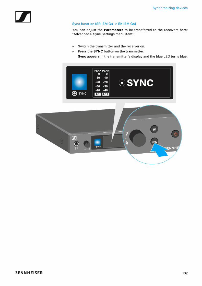
▷ Switch the transmitter and the receiver on.▷ Press the SYNC button on the transmitter.
Sync appears in the transmitter’s display and the blue LED turns blue.►
102
Synchronizing devices
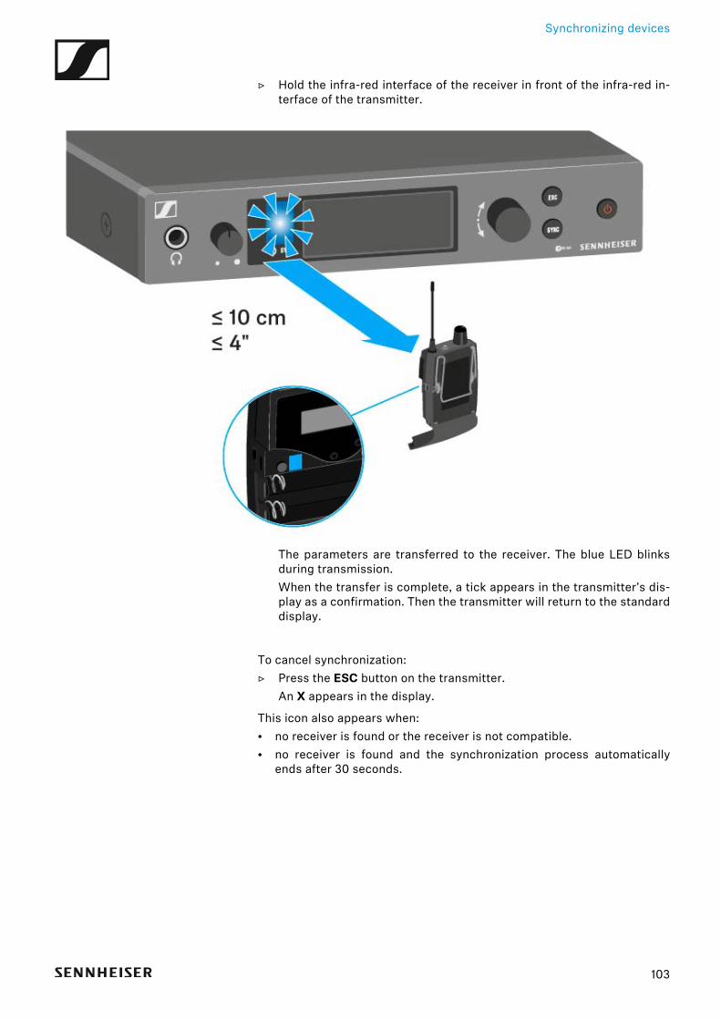
▷ Hold the infra-red interface of the receiver in front of the infra-red in-terface of the transmitter.
►
The parameters are transferred to the receiver. The blue LED blinksduring transmission.When the transfer is complete, a tick appears in the transmitter’s dis-play as a confirmation. Then the transmitter will return to the standarddisplay.
To cancel synchronization:▷ Press the ESC button on the transmitter.
An X appears in the display.
This icon also appears when:• no receiver is found or the receiver is not compatible.• no receiver is found and the synchronization process automatically
ends after 30 seconds.
103

Using the AC 41
Using the AC 41These sections contain detailed information about operating the AC 41.
You can find information on installation and startup of the AC 41 under “In-stalling the AC 41”.
104
Using the AC 41
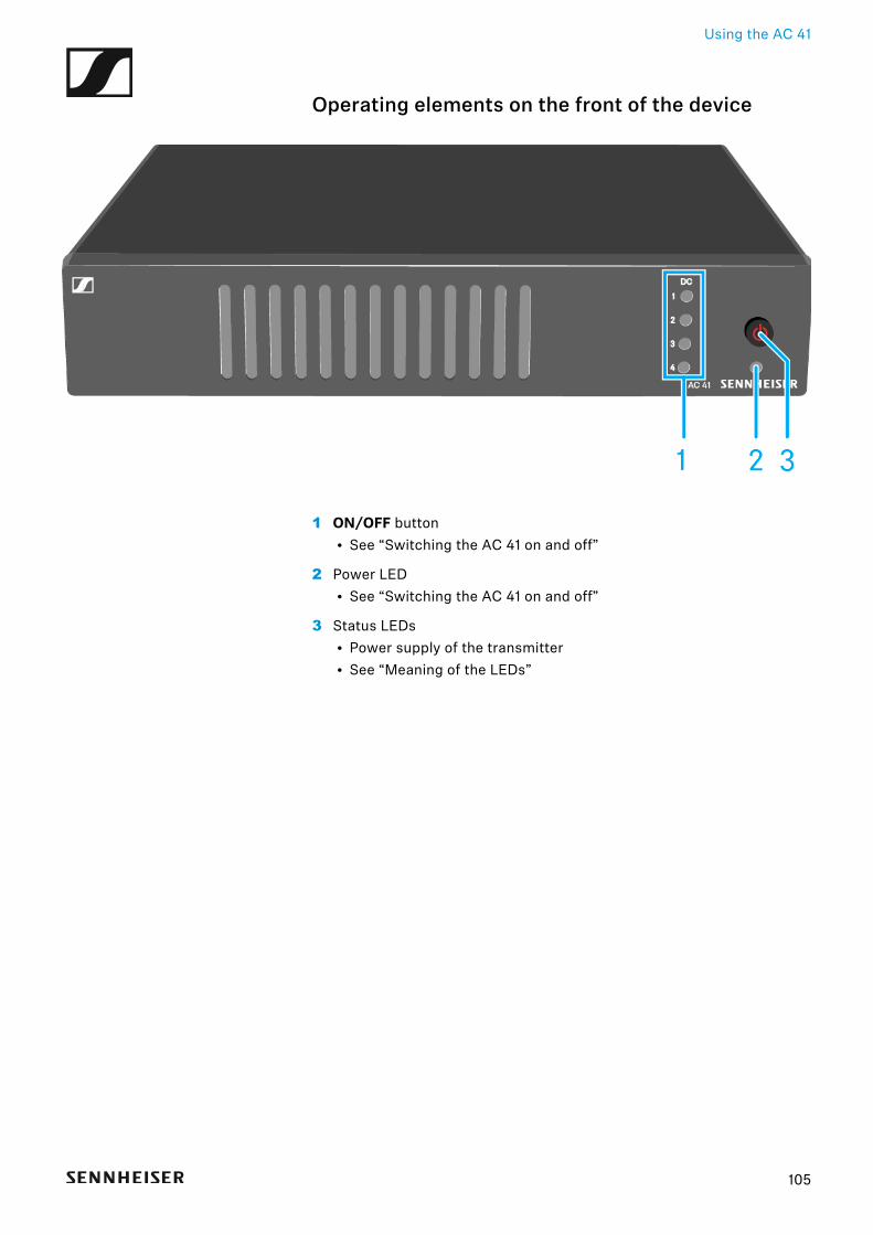
Operating elements on the front of the device
1 ON/OFF button• See “Switching the AC 41 on and off”
2 Power LED• See “Switching the AC 41 on and off”
3 Status LEDs• Power supply of the transmitter• See “Meaning of the LEDs”
105
Using the AC 41
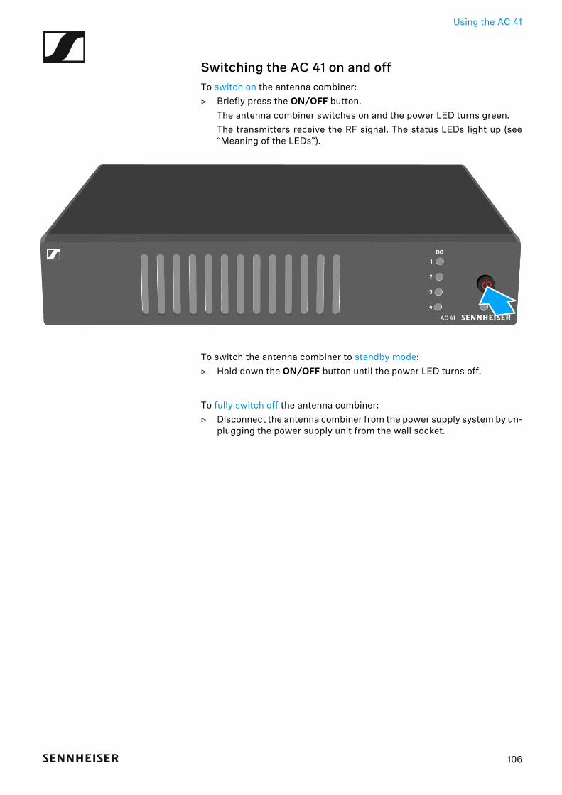
Switching the AC 41 on and offTo switch on the antenna combiner:▷ Briefly press the ON/OFF button.
The antenna combiner switches on and the power LED turns green.The transmitters receive the RF signal. The status LEDs light up (see“Meaning of the LEDs”).
To switch the antenna combiner to standby mode:▷ Hold down the ON/OFF button until the power LED turns off.
To fully switch off the antenna combiner:▷ Disconnect the antenna combiner from the power supply system by un-
plugging the power supply unit from the wall socket.
106
Using the AC 41
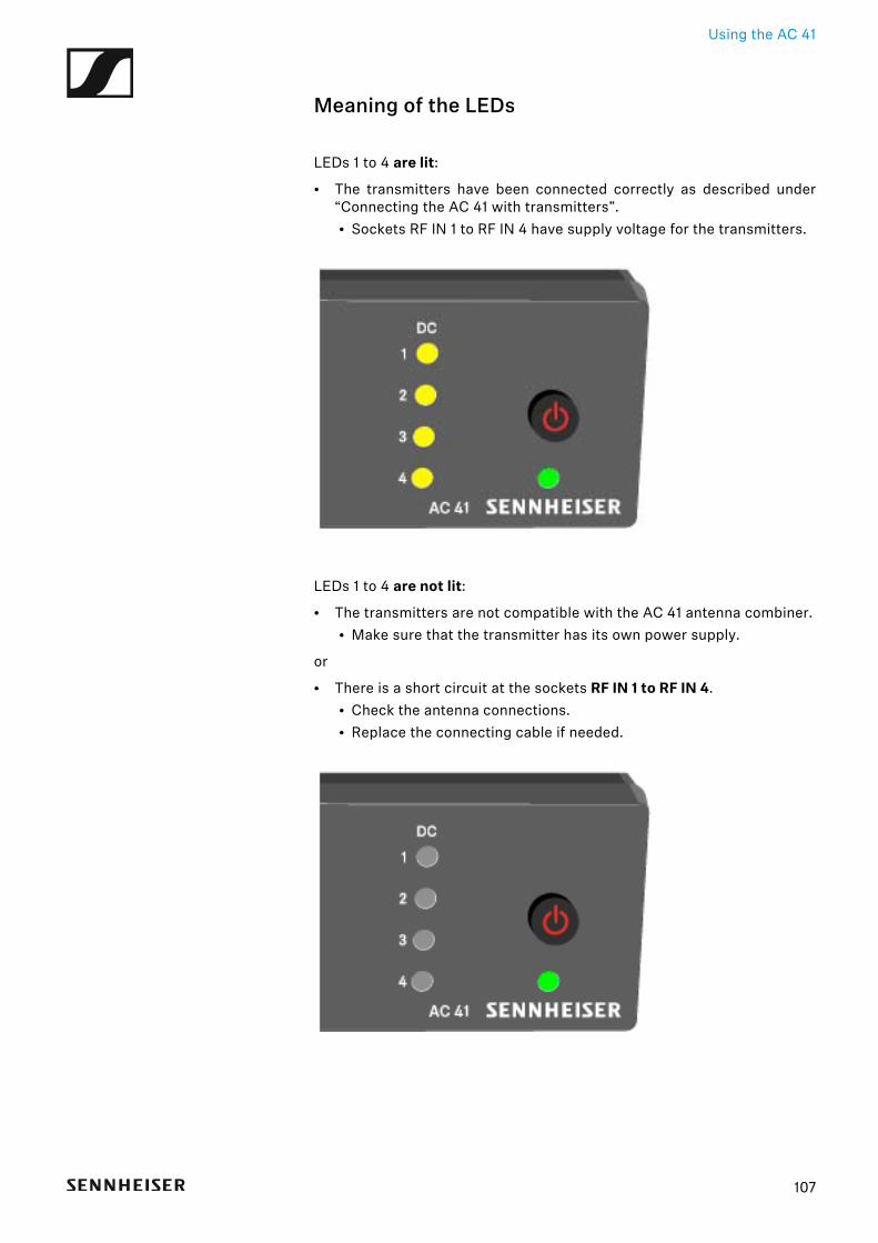
Meaning of the LEDs
LEDs 1 to 4 are lit:
• The transmitters have been connected correctly as described under“Connecting the AC 41 with transmitters”.• Sockets RF IN 1 to RF IN 4 have supply voltage for the transmitters.
LEDs 1 to 4 are not lit:
• The transmitters are not compatible with the AC 41 antenna combiner.• Make sure that the transmitter has its own power supply.
or
• There is a short circuit at the sockets RF IN 1 to RF IN 4.• Check the antenna connections.• Replace the connecting cable if needed.
107
Overview
SPECIFICATIONS
OverviewIn the sections below, you can find information about the different variantsof the products in the ew IEM G4 series as well as technical data for the in-dividual products.
• Product variants and frequency variants >> “Product variants”• Frequency tables with overviews of all banks and channels >> “Fre-
quency tables”• Product-specific technical data >> “Specifications”• Information on pin assignment (jack and XLR) >> “Pin assignment”
You can also find information about safely cleaning and maintainingevolution wireless G4 series products.
• “Cleaning and maintenance”
108
Product variants
Product variants
EK IEM G4 product variants
Made in Germany►
Assembled in the USA►
EK IEM G4-A1 470 – 516 MHz Art. no. 507849
EK IEM G4-A 516 – 558 MHz Art. no. 507850
EK IEM G4-GB 606 – 648 MHz Art. no. 507851
EK IEM G4-G 566 – 608 MHz Art. no. 507852
EK IEM G4-B 626 – 668 MHz Art. no. 507853
EK IEM G4-C 734 – 776 MHz Art. no. 507854
EK IEM G4-E 823 – 865 MHz Art. no. 507855
EK IEM G4-A1 470 – 516 MHz Art. no. 508188
EK IEM G4-A 516 – 558 MHz Art. no. 508189
EK IEM G4-AS 520 – 558 MHz Art. no. 508190
EK IEM G4-G 566 – 608 MHz Art. no. 508191
EK IEM G4-B 626 – 668 MHz Art. no. 508192
EK IEM G4-C 734 – 776 MHz Art. no. 508193
EK IEM G4-D 780 – 822 MHz Art. no. 508194
109
Product variants
SR IEM G4 product variants
Made in Germany►
Assembled in the USA►
AC 41 product variants►
SR IEM G4-A1 470 – 516 MHz Art. no. 507842
SR IEM G4-A 516 – 558 MHz Art. no. 507843
SR IEM G4-GB 606 – 648 MHz Art. no. 507844
SR IEM G4-G 566 – 608 MHz Art. no. 507845
SR IEM G4-B 626 – 668 MHz Art. no. 507846
SR IEM G4-C 734 – 776 MHz Art. no. 507847
SR IEM G4-E 823 – 865 MHz Art. no. 507848
SR IEM G4-A1 470 – 516 MHz Art. no. 508181
SR IEM G4-A 516 – 558 MHz Art. no. 508182
SR IEM G4-AS 520 – 558 MHz Art. no. 508183
SR IEM G4-G 566 – 608 MHz Art. no. 508184
SR IEM G4-B 626 – 668 MHz Art. no. 508185
SR IEM G4-C 734 – 776 MHz Art. no. 508186
SR IEM G4-D 780 – 822 MHz Art. no. 508187
AC 41-EU Art. no. 576761 NT 3-1-EU
AC 41-US Art. no. 576762 NT 3-1-US
AC 41-UK Art. no. 576761 NT 3-1-UK
110
Frequency tables
111
Frequency tablesYou can find frequency tables for all available frequency ranges in thedownload section of the Sennheiser website uneer www.sennheiser.com/download.
Download area of the Sennheiser website
Enter ew G4 into the search bar to show the frequency tables.
Specifications
112
SpecificationsYou can find the cross-system and product-specific technical data in thesections below.
EK IEM G4
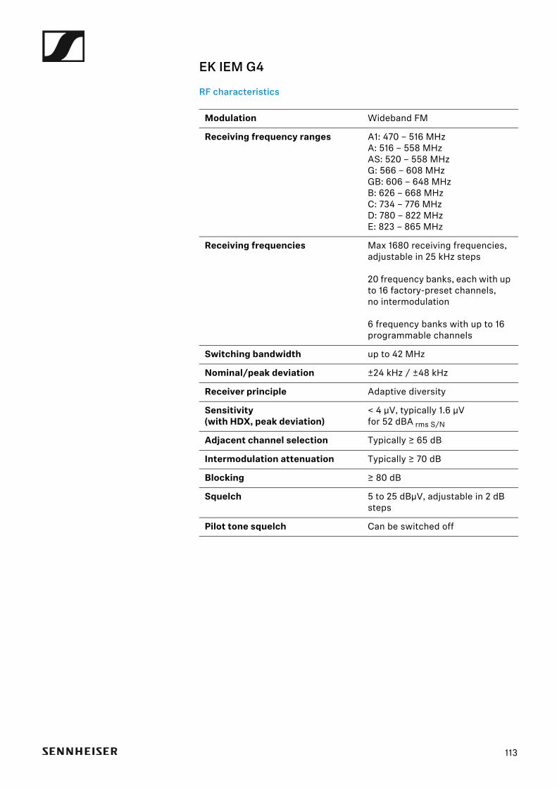
RF characteristics►
Modulation Wideband FM
Receiving frequency ranges A1: 470 – 516 MHzA: 516 – 558 MHzAS: 520 – 558 MHzG: 566 – 608 MHzGB: 606 – 648 MHzB: 626 – 668 MHzC: 734 – 776 MHzD: 780 – 822 MHzE: 823 – 865 MHz
Receiving frequencies Max 1680 receiving frequencies,adjustable in 25 kHz steps
20 frequency banks, each with up to 16 factory-preset channels, no intermodulation
6 frequency banks with up to 16 programmable channels
Switching bandwidth up to 42 MHz
Nominal/peak deviation ±24 kHz / ±48 kHz
Receiver principle Adaptive diversity
Sensitivity(with HDX, peak deviation)
< 4 μV, typically 1.6 μV for 52 dBA rms S/N
Adjacent channel selection Typically ≥ 65 dB
Intermodulation attenuation Typically ≥ 70 dB
Blocking ≥ 80 dB
Squelch 5 to 25 dBμV, adjustable in 2 dB steps
Pilot tone squelch Can be switched off
113
AF characteristics►
Overall device►
Compander system Sennheiser HDX
Signal-to-noise ratio(1 mV, peak deviation)
approx. 90 dBA
Total harmonic distortion (THD) ≤ 0.9 %
Output power at 2.4 V5% THD, nominal deviation
2 x 100 mW at 32 Ω
High Boost +8 dB at 80 kHz
Limiter –18 dB to –6 dB in 6 dB steps, can be switched off
Temperature range -10 °C to +55 °C (−13 °F to 158 °F)
Power supply 2 AA batteries, 1,5 V or BA 2015 accupack
Nominal voltage 3 V battery2.4 V rechargeable battery
Power consumption
at nominal voltagewith transmitter switched off
typically 140 mA≤ 25 μA
Operating time approx. 4 to 6 hours(depending on the volume level)
Dimensions approx. 82 x 64 x 24 mm
Weight (with batteries) Approx. 125 g
114
SR IEM G4
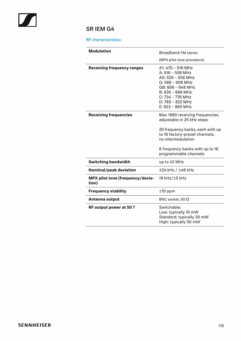
RF characteristics►
Modulation Broadband FM stereo
(MPX pilot tone procedure)
Receiving frequency ranges A1: 470 – 516 MHzA: 516 – 558 MHzAS: 520 – 558 MHzG: 566 – 608 MHzGB: 606 – 648 MHzB: 626 – 668 MHzC: 734 – 776 MHzD: 780 – 822 MHzE: 823 – 865 MHz
Receiving frequencies Max 1680 receiving frequencies,adjustable in 25 kHz steps
20 frequency banks, each with up to 16 factory-preset channels, no intermodulation
6 frequency banks with up to 16 programmable channels
Switching bandwidth up to 42 MHz
Nominal/peak deviation ±24 kHz / ±48 kHz
MPX pilot tone (frequency/devia-tion)
19 kHz/±5 kHz
Frequency stability ±10 ppm
Antenna output BNC socket, 50 Ω
RF output power at 50 ? Switchable:Low: typically 10 mWStandard: typically 30 mWHigh: typically 50 mW
115
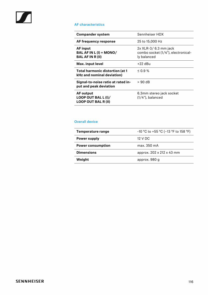
AF characteristics►
Overall device►
Compander system Sennheiser HDX
AF frequency response 25 to 15,000 Hz
AF inputBAL AF IN L (I) + MONO/BAL AF IN R (II)
2x XLR-3/ 6.3 mm jackcombo socket (1/4"), electronical-ly balanced
Max. input level +22 dBu
Total harmonic distortion (at 1 kHz and nominal deviation)
≤ 0.9 %
Signal-to-noise ratio at rated in-put and peak deviation
> 90 dB
AF outputLOOP OUT BAL L (I)/LOOP OUT BAL R (II)
6.3mm stereo jack socket (1/4"), balanced
Temperature range -10 °C to +55 °C (−13 °F to 158 °F)
Power supply 12 V DC
Power consumption max. 350 mA
Dimensions approx. 202 x 212 x 43 mm
Weight approx. 980 g
116
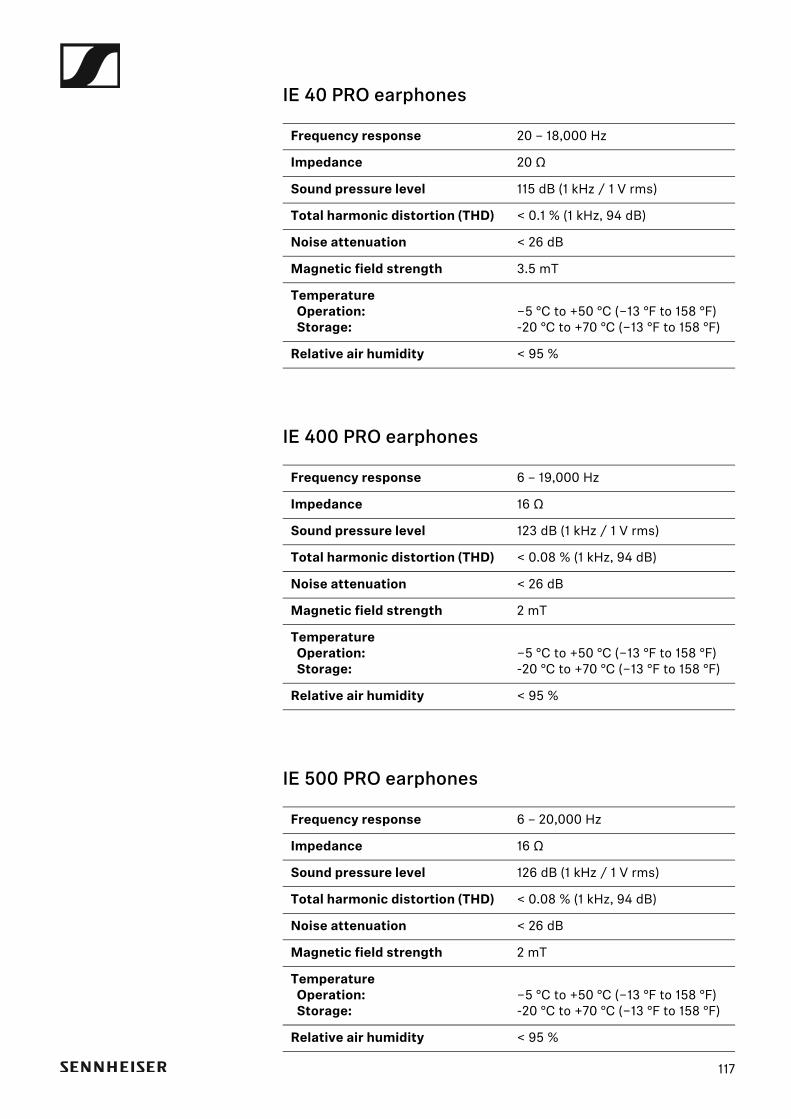
IE 40 PRO earphones►
IE 400 PRO earphones►
IE 500 PRO earphones►
Frequency response 20 – 18,000 Hz
Impedance 20 Ω
Sound pressure level 115 dB (1 kHz / 1 V rms)
Total harmonic distortion (THD) < 0.1 % (1 kHz, 94 dB)
Noise attenuation < 26 dB
Magnetic field strength 3.5 mT
Temperature Operation: Storage:
−5 °C to +50 °C (−13 °F to 158 °F)-20 °C to +70 °C (−13 °F to 158 °F)
Relative air humidity < 95 %
Frequency response 6 – 19,000 Hz
Impedance 16 Ω
Sound pressure level 123 dB (1 kHz / 1 V rms)
Total harmonic distortion (THD) < 0.08 % (1 kHz, 94 dB)
Noise attenuation < 26 dB
Magnetic field strength 2 mT
Temperature Operation: Storage:
−5 °C to +50 °C (−13 °F to 158 °F)-20 °C to +70 °C (−13 °F to 158 °F)
Relative air humidity < 95 %
Frequency response 6 – 20,000 Hz
Impedance 16 Ω
Sound pressure level 126 dB (1 kHz / 1 V rms)
Total harmonic distortion (THD) < 0.08 % (1 kHz, 94 dB)
Noise attenuation < 26 dB
Magnetic field strength 2 mT
Temperature Operation: Storage:
−5 °C to +50 °C (−13 °F to 158 °F)-20 °C to +70 °C (−13 °F to 158 °F)
Relative air humidity < 95 %
117
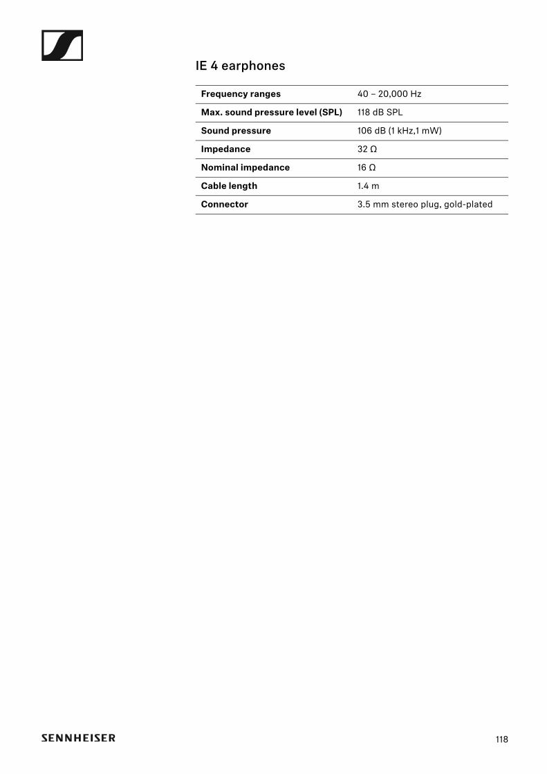
IE 4 earphones►
Frequency ranges 40 – 20,000 Hz
Max. sound pressure level (SPL) 118 dB SPL
Sound pressure 106 dB (1 kHz,1 mW)
Impedance 32 Ω
Nominal impedance 16 Ω
Cable length 1.4 m
Connector 3.5 mm stereo plug, gold-plated
118
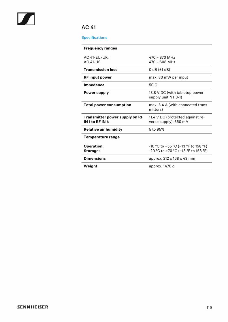
AC 41
Specifications►
Frequency ranges
AC 41-EU/UK:AC 41-US
470 – 870 MHz470 – 608 MHz
Transmission loss 0 dB (±1 dB)
RF input power max. 30 mW per input
Impedance 50 Ω
Power supply 13.8 V DC (with tabletop power supply unit NT 3-1)
Total power consumption max. 3.4 A (with connected trans-mitters)
Transmitter power supply on RF IN 1 to RF IN 4
11.4 V DC (protected against re-verse supply), 350 mA
Relative air humidity 5 to 95%
Temperature range
Operation:Storage:
-10 °C to +55 °C (−13 °F to 158 °F)-20 °C to +70 °C (−13 °F to 158 °F)
Dimensions approx. 212 x 168 x 43 mm
Weight approx. 1470 g
119
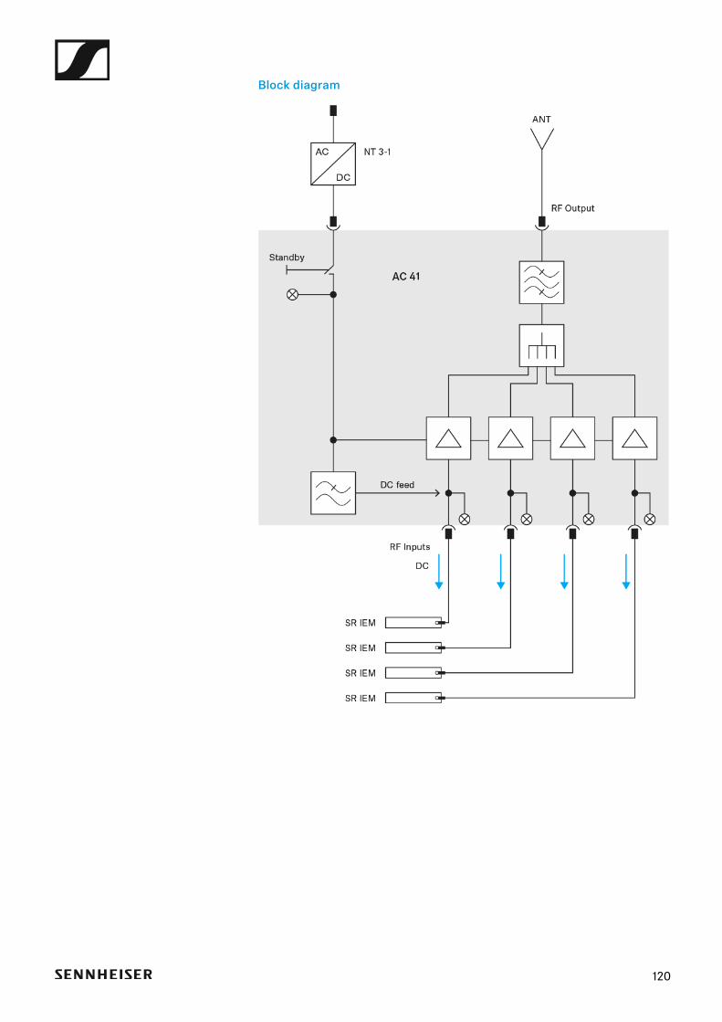
Block diagram►
120
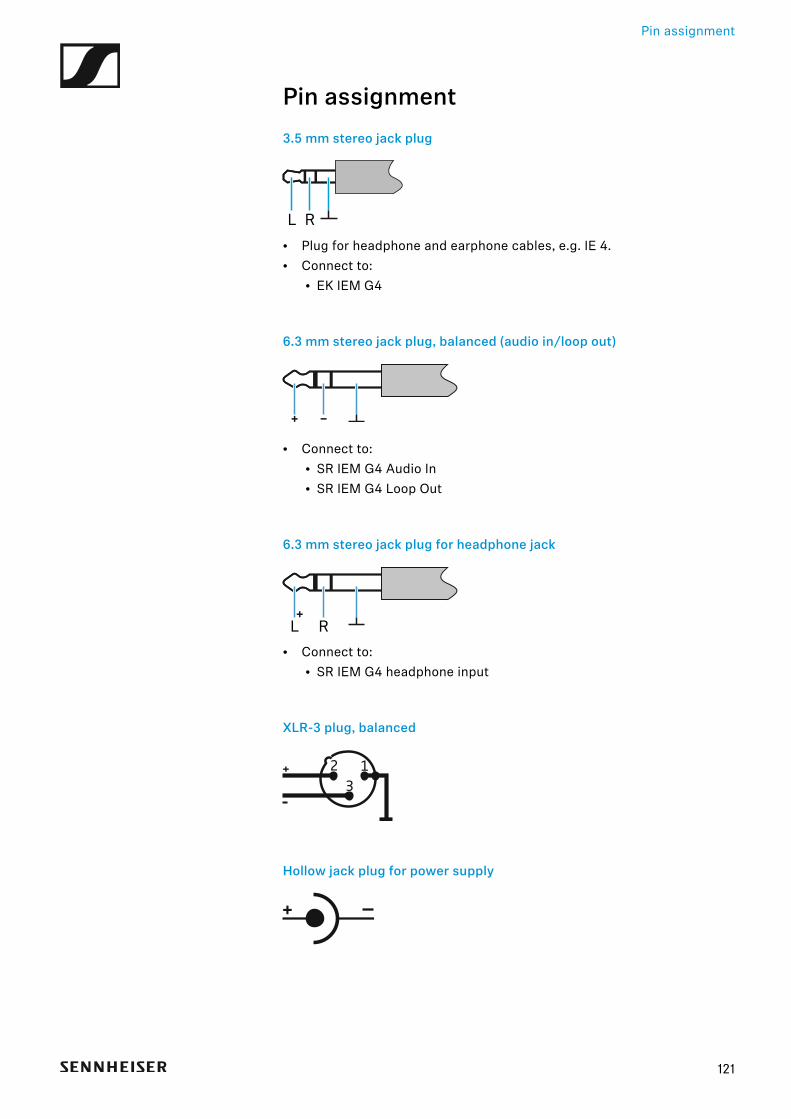
Pin assignment
121
Pin assignment3.5 mm stereo jack plug►
• Plug for headphone and earphone cables, e.g. IE 4.• Connect to:
• EK IEM G4
6.3 mm stereo jack plug, balanced (audio in/loop out)►
• Connect to:• SR IEM G4 Audio In• SR IEM G4 Loop Out
6.3 mm stereo jack plug for headphone jack►
• Connect to:• SR IEM G4 headphone input
XLR-3 plug, balanced►
Hollow jack plug for power supply►
RL
L R
13
2
Cleaning and maintenance
122
Cleaning and maintenanceNote the following information when cleaning and maintaining evolutionwireless G4 series products.
CAUTION
Liquids can damage the products’ electronics.
Liquids entering the product housing can cause a short-circuit and damagethe electronics.
▷ Keep all liquids away from the products.
▷ Do not use any solvents or cleansing agents.
▷ Disconnect the products from the power supply system and remove re-chargeable batteries and batteries before you begin cleaning.
▷ Clean all products only with a soft, dry cloth.