Embed Size (px)
DESCRIPTION
Evaporator PRINCIPLES
Citation preview
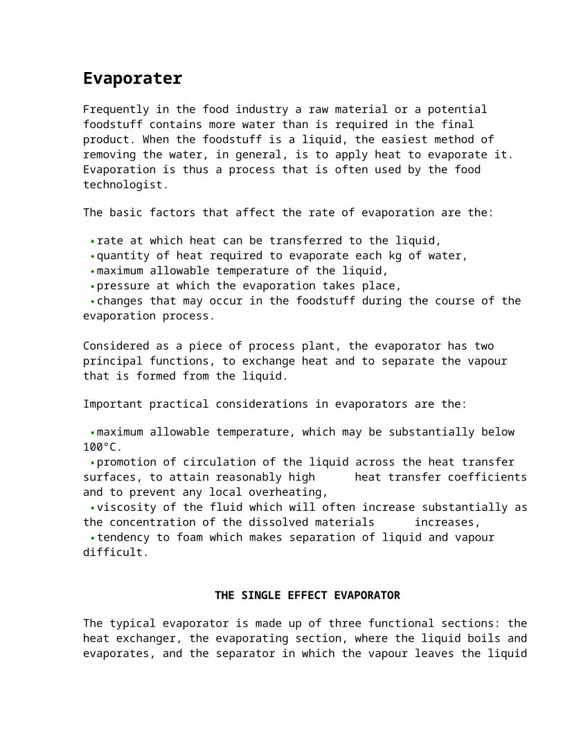
Evaporater
Frequently in the food industry a raw material or a potential foodstuff contains more water than is required in the final product. When the foodstuff is a liquid, the easiest method of removing the water, in general, is to apply heat to evaporate it. Evaporation is thus a process that is often used by the food technologist.
The basic factors that affect the rate of evaporation are the:
rate at which heat can be transferred to the liquid,quantity of heat required to evaporate each kg of water,maximum allowable temperature of the liquid,pressure at which the evaporation takes place,changes that may occur in the foodstuff during the course of the evaporation process.
Considered as a piece of process plant, the evaporator has two principal functions, to exchange heat and to separate the vapour that is formed from the liquid.
Important practical considerations in evaporators are the:
maximum allowable temperature, which may be substantially below 100°C.promotion of circulation of the liquid across the heat transfer surfaces, to attain
reasonably high heat transfer coefficients and to prevent any local overheating,viscosity of the fluid which will often increase substantially as the concentration of the
dissolved materials increases,tendency to foam which makes separation of liquid and vapour difficult.
THE SINGLE EFFECT EVAPORATOR
The typical evaporator is made up of three functional sections: the heat exchanger, the evaporating section, where the liquid boils and evaporates, and the separator in which the vapour leaves the liquid and passes off to the condenser or to other equipment. In many evaporators, all three sections are contained in a single vertical cylinder. In the centre of the cylinder there is a steam heating section, with pipes passing through it in which the evaporating liquors rise. At the top of the cylinder, there are baffles, which allow the vapours to escape but check liquid droplets that may accompany the vapours from the liquid surface. A diagram of this type of evaporator, which may be called the conventional evaporator, is given in Fig. 8.1.
In the heat exchanger section, called a calandria in this type of evaporator, steam condenses in the outer jacket and the liquid being evaporated boils on the inside of the tubes and in the space above the upper tube plate. The resistance to heat flow is imposed by the steam and liquid film coefficients and by the material of the tube walls. The circulation of the liquid greatly affects evaporation rates, but circulation rates and patterns are very difficult to predict in any detail. Values of overall heat transfer coefficients that have been reported for evaporators are of the order of 1800-5000 J m-2 s-1 °C-1 for the evaporation of distilled water in a vertical-tube evaporator with heat supplied by condensing steam. However, with dissolved solids in increasing quantities as evaporation proceeds leading to increased viscosity and poorer circulation, heat transfer coefficients in practice may be much lower than this.
As evaporation proceeds, the remaining liquors become more concentrated and because of this the boiling temperatures rise. The rise in the temperature of boiling reduces the available temperature drop, assuming no change in the heat source. And so the total rate of heat transfer will drop accordingly. Also, with increasing solute concentration, the viscosity of the liquid will increase, often quite substantially, and this affects circulation and the heat transfer coefficients leading again to lower rates of boiling. Yet another complication is that measured, overall, heat transfer coefficients have been found to vary with the actual temperature drop, so that the design of an evaporator on theoretical grounds is inevitably subject to wide margins of uncertainty.
Perhaps because of this uncertainty, many evaporator designs have tended to follow traditional patterns of which the calandria type of Fig. 8.1 is a typical example.
Vacuum Evaporation
For the evaporation of liquids that are adversely affected by high temperatures, it may be necessary to reduce the temperature of boiling by operating under reduced pressure. The relationship between vapour pressure and boiling temperature, for water, is shown in Fig. 7.2. When the vapour pressure of the liquid reaches the pressure of its surroundings, the liquid boils. The reduced pressures required to boil the liquor at lower temperatures are obtained by mechanical or steam jet ejector vacuum pumps, combined generally with condensers for the vapours from the evaporator. Mechanical vacuum pumps are generally cheaper in running costs but more expensive in terms of capital than are steam jet ejectors. The condensed liquid can either be pumped from the system or discharged through a tall barometric column in which a static column of liquid balances the atmospheric pressure. Vacuum pumps are then left to deal with the non-condensibles, which of course are much less in volume but still have to be discharged to the atmosphere.
Heat Transfer in Evaporators
Heat transfer in evaporators is governed by the equations for heat transfer to boiling liquids and by the convection and conduction equations. The heat must be provided from a source at a suitable temperature and this is condensing steam in most cases. The steam comes either directly from a boiler or from a previous stage of evaporation in another evaporator. Major objections to other forms of heating, such as direct firing or electric resistance heaters, arise because of the need to avoid local high temperatures and because of the high costs in the case of electricity. In some cases the temperatures of condensing steam may be too high for the product and hot water may be used. Low-pressure steam can also be used but the large volumes create design problems.
Calculations on evaporators can be carried out combining mass and energy balances with the principles of heat transfer.
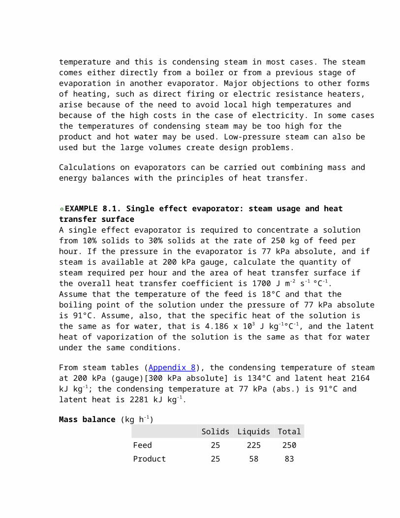
EXAMPLE 8.1. Single effect evaporator: steam usage and heat transfer surfaceA single effect evaporator is required to concentrate a solution from 10% solids to 30% solids at the rate of 250 kg of feed per hour. If the pressure in the evaporator is 77 kPa absolute, and if steam is available at 200 kPa gauge, calculate the quantity of steam required per hour and the area of heat transfer surface if the overall heat transfer coefficient is 1700 J m-2 s-1 °C-1. Assume that the temperature of the feed is 18°C and that the boiling point of the solution under the pressure of 77 kPa absolute is 91°C. Assume, also, that the specific heat of the solution is the same as for water, that is 4.186 x 10³ J kg-1°C-1, and the latent heat of vaporization of the solution is the same as that for water under the same conditions.
From steam tables (Appendix 8), the condensing temperature of steam at 200 kPa (gauge)[300 kPa absolute] is 134°C and latent heat 2164 kJ kg-1; the condensing temperature at 77 kPa (abs.) is 91°C and latent heat is 2281 kJ kg-1.
Mass balance (kg h-1) Solids Liquids Total
Feed 25 225 250
Product 25 58 83
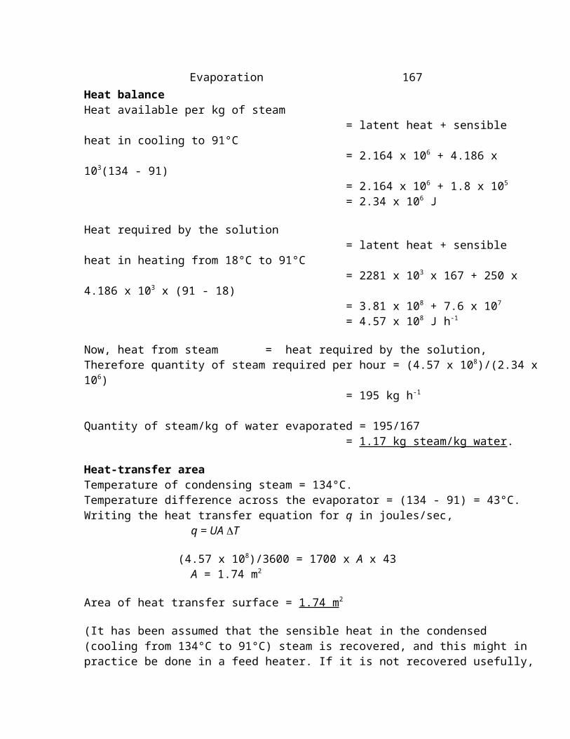
Evaporation 167Heat balanceHeat available per kg of steam = latent heat + sensible heat in cooling to 91°C = 2.164 x 10⁶ + 4.186 x 10³(134 - 91) = 2.164 x 10⁶ + 1.8 x 105
= 2.34 x 10⁶ J
Heat required by the solution
= latent heat + sensible heat in heating from 18°C to 91°C = 2281 x 103 x 167 + 250 x 4.186 x 103 x (91 - 18) = 3.81 x 10⁸ + 7.6 x 107
= 4.57 x 10⁸ J h-1
Now, heat from steam = heat required by the solution,Therefore quantity of steam required per hour = (4.57 x 10⁸)/(2.34 x 106) = 195 kg h-1
Quantity of steam/kg of water evaporated = 195/167 = 1.17 kg steam/kg water.
Heat-transfer areaTemperature of condensing steam = 134°C.Temperature difference across the evaporator = (134 - 91) = 43°C.Writing the heat transfer equation for q in joules/sec, q = UA T
(4.57 x 10⁸)/3600 = 1700 x A x 43 A = 1.74 m2
Area of heat transfer surface = 1.74 m2
(It has been assumed that the sensible heat in the condensed (cooling from 134°C to 91°C) steam is recovered, and this might in practice be done in a feed heater. If it is not recovered usefully, then the sensible heat component, about 8%, should be omitted from the heat available, and the remainder of the working adjusted accordingly).
Condensers
In evaporators that are working under reduced pressure, a condenser, to remove the bulk of the volume of the vapours by condensing them to a liquid, often precedes the vacuum pump. Condensers for the vapour may be either surface or jet condensers. Surface condensers provide sufficient heat transfer surface, pipes for example, through which the condensing vapour transfers latent heat of vaporization to cooling water circulating through the pipes. In a jet condenser, the vapours are mixed with a stream of condenser water sufficient in quantity to transfer latent heat from the vapours.
EXAMPLE 8.2. Water required in a jet condenser for an evaporatorHow much water would be required in a jet condenser to condense the vapours from an evaporator evaporating 5000 kg h-1 of water under a pressure of 15 cm of mercury? The condensing water is available at 18°C and the highest allowable temperature for water
discharged from the condenser is 35°C.
Heat balance
The pressure in the evaporator is 15 cm mercury = Zg = 0.15 x 13.6 x 1000 x 9.81 = 20 kPa. From Steam Tables, the condensing temperature of water under pressure of 20 kPa is 60°C and the corresponding latent heat of vaporization is 2358 kJ kg-1.
Heat removed from condensate = 2358 x 103 + (60 - 35) x 4.186 x 103
= 2.46 x 10⁶ J kg-1
Heat taken by cooling water = (35 - 18) x 4.186 x 103
= 7.1 x 10⁴ J kg-1
Quantity of heat removed from condensate per hour = 5000 x 2.46 x 106 JTherefore quantity of cooling water per hour = (5000 x 2.46 x 106)/7.1 x 104
= 1.7 x 10⁵ kg
EXAMPLE 8.3. Heat exchange area for a surface condenser for an evaporatorWhat heat exchange area would be required for a surface condenser working under the same conditions as the jet condenser in Example 8.2, assuming a U value of 2270 J m-2 s-1 °C-1, and disregarding any sub-cooling of the liquid.
The temperature differences are small so that the arithmetic mean temperature can be used for the heat exchanger (condenser). Mean temperature difference = (60 - 18)/2 + (60 - 35)/2 = 33.5°C.
The data are available from the previous Example, and remembering to put time in hours.Quantity of heat required by condensate = UA T 5000 x 2.46 x 106 = 2270 x A x 33.5 x 3600and so A = 45 m2
Heat transfer area required = 45 m2
This would be a large surface condenser so that a jet condenser is often preferred.
An evaporator is essentially a heat exchanger in which a liquid is boiled to give a vapour, so that it is also, simultaneously, a low pressure steam generator. It may be possible to make use of this, to treat an evaporator as a low pressure boiler, and to make use of the steam
thus produced for further heating in another following evaporator called another effect.
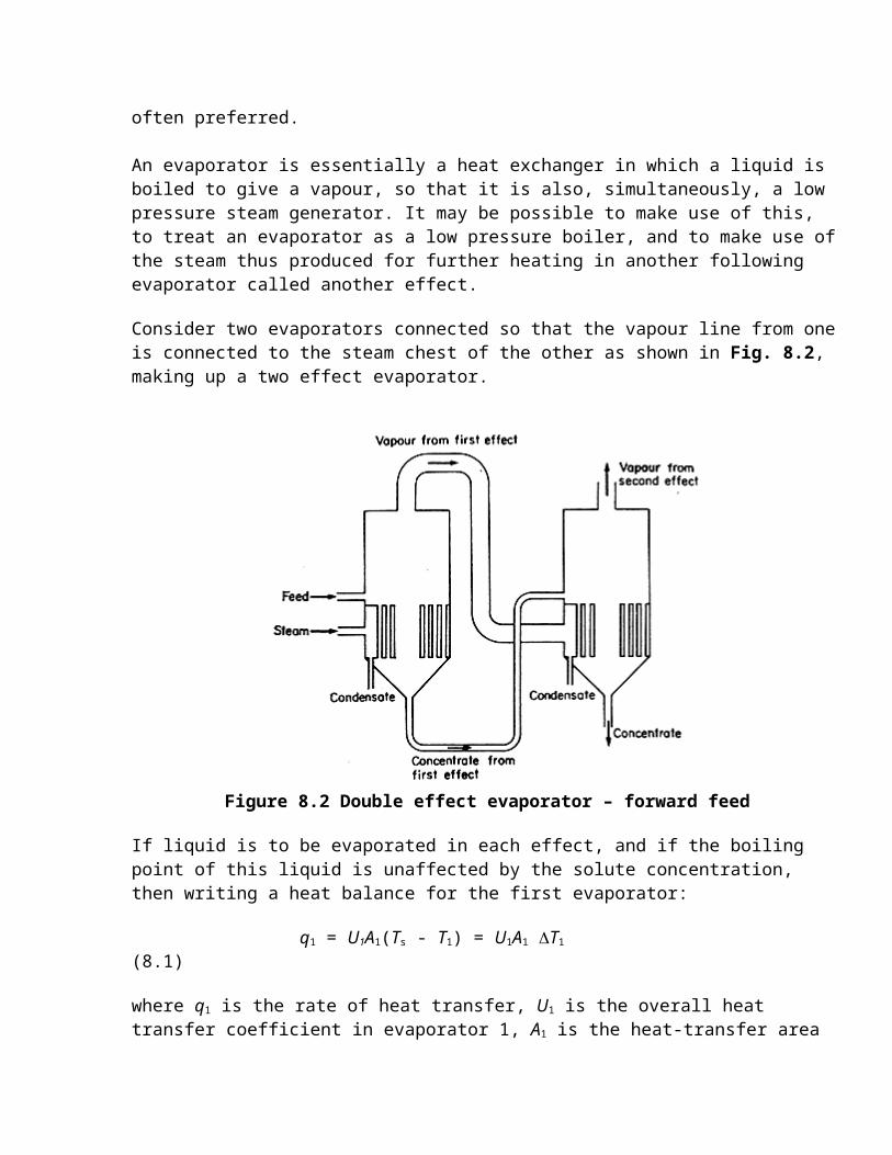
Consider two evaporators connected so that the vapour line from one is connected to the steam chest of the other as shown in Fig. 8.2, making up a two effect evaporator.
Figure 8.2 Double effect evaporator – forward feed
If liquid is to be evaporated in each effect, and if the boiling point of this liquid is unaffected by the solute concentration, then writing a heat balance for the first evaporator:
q1 = U1A1(Ts - T1) = U1A1 T1 (8.1)
where q1 is the rate of heat transfer, U1 is the overall heat transfer coefficient in evaporator 1, A1 is the heat-transfer area in evaporator 1, Ts is the temperature of condensing steam from the boiler, T1 is the boiling temperature of the liquid in evaporator 1 and T1 is the temperature difference in evaporator 1, = (Ts - T1).
Similarly, in the second evaporator, remembering that the "steam" in the second is the vapour from the first evaporator and that this will condense at approximately the same temperature as it boiled, since pressure changes are small,
q2 = U2A2(T1 - T2) = U2A2 T2
in which the subscripts 2 indicate the conditions in the second evaporator.
If the evaporators are working in balance, then all of the vapours from the first effect are condensing and in their turn evaporating vapours in the second effect. Also assuming that heat losses can be neglected, there is no appreciable boiling-point elevation of the more
concentrated solution, and the feed is supplied at its boiling point,
q1 = q2
Further, if the evaporators are so constructed that A1 = A2, the foregoing equations can be combined.
U2/U1 = T1/T2. (8.2)
Equation (8.2) states that the temperature differences are inversely proportional to the overall heat transfer coefficients in the two effects. This analysis may be extended to any number of effects operated in series, in the same way.
Feeding of Multiple Effect Evaporators
In a two effect evaporator, the temperature in the steam chest is higher in the first than in the second effect. In order that the steam provided by the evaporation in the first effect will boil off liquid in the second effect, the boiling temperature in the second effect must be lower and so that effect must be under lower pressure.
Consequently, the pressure in the second effect must be reduced below that in the first. In some cases, the first effect may be at a pressure above atmospheric; or the first effect may be at atmospheric pressure and the second and subsequent effects have therefore to be under increasingly lower pressures. Often many of the later effects are under vacuum. Under these conditions, the liquid feed progress is simplest if it passes from effect one to effect two, to effect three, and so on, as in these circumstances the feed will flow without pumping. This is called forward feed. It means that the most concentrated liquids will occur in the last effect. Alternatively, feed may pass in the reverse direction, starting in the last effect and proceeding to the first, but in this case the liquid has to be pumped from one effect to the next against the pressure drops. This is called backward feed and because the concentrated viscous liquids can be handled at the highest temperatures in the first effects it usually offers larger evaporation capacity than forward feed systems, but it may be disadvantageous from the viewpoint of product quality.
Advantages of Multiple Effect Evaporators
At first sight, it may seem that the multiple effect evaporator has all the advantages, the heat is used over and over again and we appear to be getting the evaporation in the second and subsequent effects for nothing in terms of energy costs. Closer examination shows, however, that there is a price to be paid for the heat economy.
In the first effect, q1 = U1A1T1 and in the second effect, q2 = U2A2T2.
We shall now consider a single-effect evaporator, working under the same pressure as the first effect qs = UsAsTs, where subscript s indicates the single-effect evaporator.
Since the overall conditions are the same, Ts = T1+ T2, as the overall temperature drop is between the steam-condensing temperature in the first effect and the evaporating temperature in the second effect. Each successive steam chest in the multiple-effect evaporator condenses at the same temperature as that at which the previous effect is evaporating.
Now, consider the case in which U1 = U2 = Us, and A1 = A2. The problem then becomes to find As for the single-effect evaporator that will evaporate the same quantity as the two effects.
From the given conditions and from eqn. (8.2),
T1 = T2
and Ts= T1 + T2 = 2T1
T1 = 0.5Ts
Now q1 + q2 = U1A1T1 + U2A2T2
= U1(A1+ A2) Ts/2 but q1 + q2 = qs
and qs = UAsTs
so that (A1 + A2)/2 = 2A1/2 = As
That is A1 = A2 = As
The analysis shows that if the same total quantity is to be evaporated, then the heat transfer surface of each of the two effects must be the same as that for a single effect evaporator working between the same overall conditions. The analysis can be extended to cover any number of effects and leads to the same conclusions. In multiple effect evaporators, steam economy has to be paid for by increased capital costs of the evaporators. Since the heat transfer areas are generally equal in the various effects and since in a sense what you are buying in an evaporator is suitable heat transfer surface, the n effects will cost approximately n times as much as a single effect.
Comparative costs of the auxiliary equipment do not altogether follow the same pattern. Condenser requirements are less for multiple effect evaporators. The condensation duty is distributed between the steam chests of the effects, except for the first one, and so condenser and cooling water requirements will be less. The optimum design of evaporation plant must then be based on a balance between operating costs which are lower for
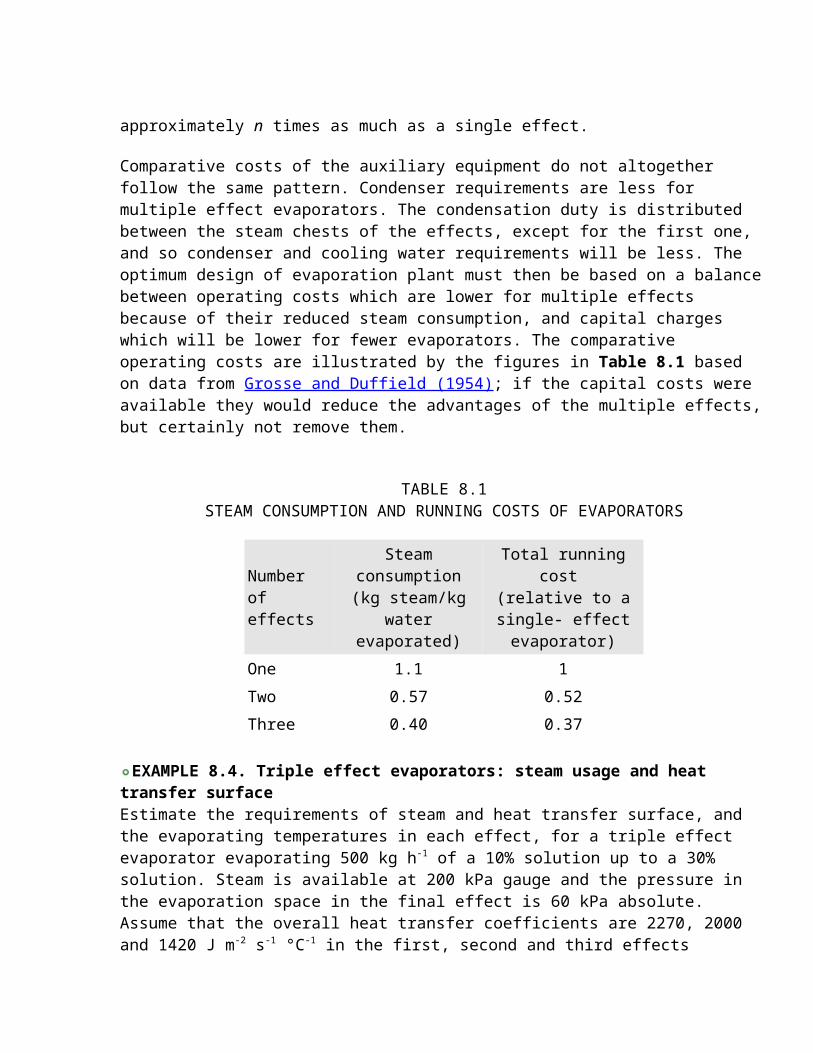
multiple effects because of their reduced steam consumption, and capital charges which will be lower for fewer evaporators. The comparative operating costs are illustrated by the figures in Table 8.1 based on data from Grosse and Duffield (1954); if the capital costs were available they would reduce the advantages of the multiple effects, but certainly not remove them.
TABLE 8.1STEAM CONSUMPTION AND RUNNING COSTS OF EVAPORATORS
Number of effects
Steam consumption(kg steam/kg water
evaporated)
Total running cost (relative to a single- effect evaporator)
One 1.1 1
Two 0.57 0.52
Three 0.40 0.37
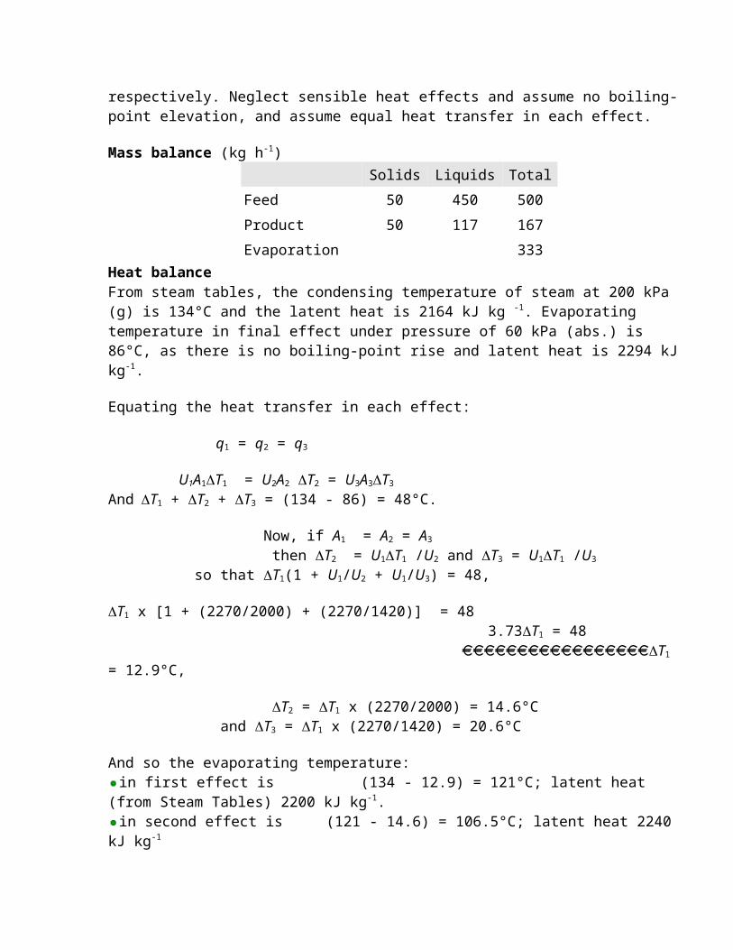
EXAMPLE 8.4. Triple effect evaporators: steam usage and heat transfer surface Estimate the requirements of steam and heat transfer surface, and the evaporating temperatures in each effect, for a triple effect evaporator evaporating 500 kg h-1 of a 10% solution up to a 30% solution. Steam is available at 200 kPa gauge and the pressure in the evaporation space in the final effect is 60 kPa absolute. Assume that the overall heat transfer coefficients are 2270, 2000 and 1420 J m-2 s-1 °C-1 in the first, second and third effects respectively. Neglect sensible heat effects and assume no boiling-point elevation, and assume equal heat transfer in each effect.
Mass balance (kg h-1) Solids Liquids Total
Feed 50 450 500
Product 50 117 167
Evaporation 333Heat balanceFrom steam tables, the condensing temperature of steam at 200 kPa (g) is 134°C and the latent heat is 2164 kJ kg -1. Evaporating temperature in final effect under pressure of 60 kPa (abs.) is 86°C, as there is no boiling-point rise and latent heat is 2294 kJ kg-1.
Equating the heat transfer in each effect:
q1 = q2 = q3
U1A1T1 = U2A2 T2 = U3A3T3 AndT1 + T2 + T3 = (134 - 86) = 48°C.
Now, if A1 = A2 = A3
then T2 = U1T1 /U2 and T3 = U1T1 /U3
so that T1(1 + U1/U2 + U1/U3) = 48,
T1 x [1 + (2270/2000) + (2270/1420)] = 48 3.73T1 = 48 T1 = 12.9°C,
T2 = T1 x (2270/2000) = 14.6°C and T3 = T1 x (2270/1420) = 20.6°C
And so the evaporating temperature:in first effect is (134 - 12.9) = 121°C; latent heat (from Steam Tables) 2200 kJ kg-1. in second effect is (121 - 14.6) = 106.5°C; latent heat 2240 kJ kg-1
in the third effect is (106.5 - 20.6) = 86°C, latent heat 2294 kJ kg-1
Equating the quantities evaporated in each effect and neglecting the sensible heat changes, if w1, w2, w3 are the respective quantities evaporated in effects 1,2 and 3, and ws is the quantity of steam condensed per hour in effect 1, then
w1 x 2200 x 103 = w2 x 2240 x 103
= w3 x 2294 x 103
= ws x 2164 x 103
The sum of the quantities evaporated in each effect must equal the total evaporated in all three effects so that:
w1 + w2 + w3 = 333 and solving as above,
w1 = 113 kg h-1 w2 = 111kg h-1 w3 = 108kg h-1
ws = 115 kg h-1
Steam consumptionIt required 115 kg steam (ws) to evaporate a total of 333 kg water, that is 0.35kg steam/kg water evaporated.
Heat exchanger surface.Writing a heat balance on the first effect:
(113 x 2200 x 1000)/3600 = 2270 x A1 x 12.9 A1 = 2.4 m2 = A2 = A3
total area = A 1 + A 2 + A 3 = 7.2 m2.
Note that the conditions of this example are considerably simplified, in that sensible heat
and feed heating effects are neglected, and no boiling-point rise occurs. The general method remains the same in the more complicated cases, but it is often easier to solve the heat balance equations by trial and error rather than by analytical methods, refining the approximations as far as necessary
VAPOUR RECOMPRESSION
In addition to the possibility of taking the steam from one effect and using it in the steam chest of another, a further possibility for economy of steam is to take the vapour and, after compressing it, return it to the steam chest of the evaporator from which it was evaporated.
The compression can be effected either by using some fresh steam, at a suitably high pressure, in a jet ejector pump, or by mechanical compressors. The use of jet ejectors is the more common. By this means a proportion of the vapours are re-used, together with fresh steam, and so considerable overall steam economy is achieved by reusing the latent heat of the vapours over again. The price to be paid for the recompression can be either in the pressure drop of the fresh steam (which may be wasted through a reducing valve in any case) or in the mechanical energy expended in mechanical compressors. Vapour recompression is similar in many ways to the use of multiple effects. The available temperature in the fresh steam is reduced before use for evaporation and so additional heat exchange surface has to be provided: roughly one stage equals one extra effect.
The steam economy of an evaporator is also affected by the temperature of the feed. If the feed is not at its boiling point, heat has to be used in raising it to this temperature. A convenient source of this feed pre-heat may be in the vapours from a single effect evaporator; a separate feed pre-heater can be used for this purpose.
BOILING-POINT ELEVATION
As evaporation proceeds, the liquor remaining in the evaporator becomes more concentrated and its boiling point will rise. The extent of the boiling-point elevation depends upon the nature of the material being evaporated and upon the concentration changes that are produced. The extent of the rise can be predicted by Raoult's Law, which leads to:
T = kx (8.3)
where T is the boiling point elevation, x is the mole fraction of the solute and k is a constant of proportionality.
In multiple effect evaporators, where the effects are fed in series, the boiling points will rise from one effect to the next as the concentrations rise. Relatively less of the apparent temperature drops are available for heat transfer, although boiling points are higher, as the condensing temperature of the vapour in the steam chest of the next effect is still that of the pure vapour. Boiling-point elevation complicates evaporator analysis but heat balances can
still be drawn up along the lines indicated previously. Often foodstuffs are made up from large molecules in solution, in which boiling-point elevation can to a greater extent be ignored.
As the concentrations rise, the viscosity of the liquor also rises. The increase in the viscosity of the liquor affects the heat transfer and it often imposes a limit on the extent of evaporation that is practicable.
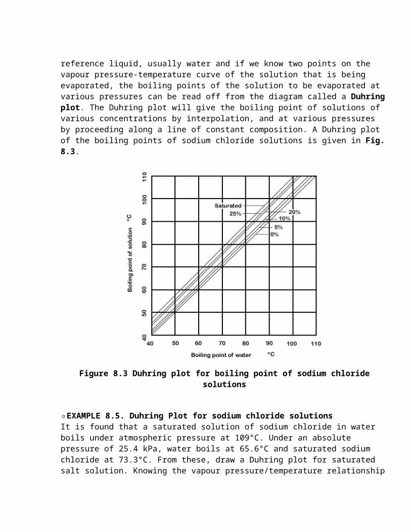
There is no straightforward method of predicting the extent of the boiling-point elevation in the concentrated solutions that are met in some evaporators in practical situations. Many solutions have their boiling points at some concentrations tabulated in the literature, and these can be extended by the use of a relationship known as Duhring's rule. Duhring's rule states that the ratio of the temperatures at which two solutions (one of which can be pure water) exert the same vapour pressure is constant. Thus, if we take the vapour pressure/temperature relation of a reference liquid, usually water and if we know two points on the vapour pressure-temperature curve of the solution that is being evaporated, the boiling points of the solution to be evaporated at various pressures can be read off from the diagram called a Duhring plot. The Duhring plot will give the boiling point of solutions of various concentrations by interpolation, and at various pressures by proceeding along a line of constant composition. A Duhring plot of the boiling points of sodium chloride solutions is given in Fig. 8.3.
Figure 8.3 Duhring plot for boiling point of sodium chloride solutions
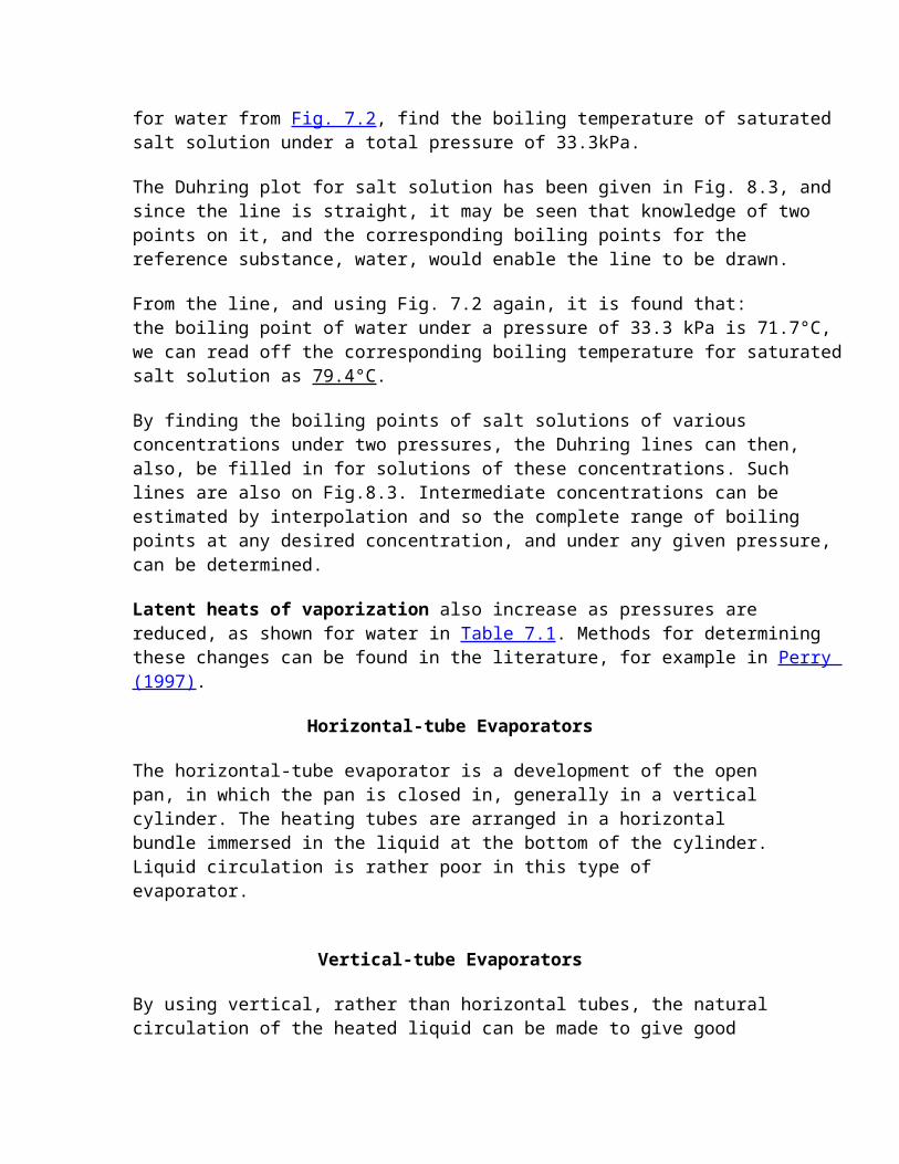
EXAMPLE 8.5. Duhring Plot for sodium chloride solutions It is found that a saturated solution of sodium chloride in water boils under atmospheric pressure at 109°C. Under an absolute pressure of 25.4 kPa, water boils at 65.6°C and saturated sodium chloride at 73.3°C. From these, draw a Duhring plot for saturated salt solution. Knowing the vapour pressure/temperature relationship for water from Fig. 7.2, find the boiling temperature of saturated salt solution under a total pressure of 33.3kPa.
The Duhring plot for salt solution has been given in Fig. 8.3, and since the line is straight, it may be seen that knowledge of two points on it, and the corresponding boiling points for the reference substance, water, would enable the line to be drawn.
From the line, and using Fig. 7.2 again, it is found that:the boiling point of water under a pressure of 33.3 kPa is 71.7°C, we can read off the corresponding boiling temperature for saturated salt solution as 79.4°C.
By finding the boiling points of salt solutions of various concentrations under two pressures, the Duhring lines can then, also, be filled in for solutions of these concentrations. Such lines are also on Fig.8.3. Intermediate concentrations can be estimated by interpolation and so the complete range of boiling points at any desired concentration, and under any given pressure, can be determined.
Latent heats of vaporization also increase as pressures are reduced, as shown for water in Table 7.1. Methods for determining these changes can be found in the literature, for example in Perry (1997).
Horizontal-tube Evaporators
The horizontal-tube evaporator is a development of the open pan, in which the pan is closed in, generally in a vertical cylinder. The heating tubes are arranged in a horizontal bundle immersed in the liquid at the bottom of the cylinder. Liquid circulation is rather poor in this type of evaporator.
Vertical-tube Evaporators
By using vertical, rather than horizontal tubes, the natural circulation of the heated liquid can be made to give good heat transfer. The standard evaporator, shown in Fig. 8.1, is an example of this type. Recirculation of the liquid is through a large “downcomer” so that the liquors rise through the vertical tubes about 5-8 cm diameter, boil in the space just above the upper tube plate and recirculate through the downcomers. The hydrostatic head reduces boiling on the lower tubes, which are covered by the circulating liquid. The length to diameter ratio of the tubes is of the order of 15:1. The basket evaporator shown in Fig. 8.4(a) is a variant of the calandria evaporator in which the steam chest is contained in a
basket suspended in the lower part of the evaporator, and recirculation occurs through the annular space round the basket.
Figure 8.4 Evaporators (a) basket type (b) long tube (c) forced circulation
Plate Evaporators
The plate heat exchanger can be adapted for use as an evaporator. The spacings can be increased between the plates and appropriate passages provided so that the much larger volume of the vapours, when compared with the liquid, can be accommodated. Plate evaporators can provide good heat transfer and also ease of cleaning.
Long tube Evaporators
Tall slender vertical tubes may be used for evaporators as shown in Fig. 8.4(b). The tubes, which may have a length to diameter ratio of the order of 100:1, pass
vertically upward inside the steam chest. The liquid may either pass down through the tubes, called a falling- ilm evaporator, or be carried up by the evaporating liquor in which case it is called a climbing-film evaporator. Evaporation occurs on the walls of the tubes. Because circulation rates are high and the surface films are thin, good conditions are obtained for the concentration of heat sensitive liquids due to high heat transfer rates and short heating times.
Generally, the liquid is not recirculated, and if sufficient evaporation does not occur in one pass, the liquid is fed to another pass. In the climbing-film evaporator, as the liquid boils on the inside of the tube slugs of vapour form and this vapour carries up the remaining liquid which continues to boil. Tube diameters are of the order of 2.5 to 5 cm, contact times may be as low as 5-10 sec. Overall heat- transfer coefficients may be up to five times as great as from a heated surface immersed in a boiling liquid. In the falling-film type, the tube diameters are rather greater, about 8 cm, and these are specifically suitable for viscous liquids.
Forced circulation Evaporators
The heat transfer coefficients from condensing steam are high, so that the major resistance to heat flow in an evaporator is usually in the liquid film. Tubes are generally made of metals with a high thermal conductivity, though scale formation may occur on the tubes which reduce the tube conductance.
The liquid-film coefficients can be increased by improving the circulation of the liquid and by increasing its velocity of flow across the heating surfaces. Pumps, or impellers, can be fitted in the liquid circuit to help with this. Using pump circulation, the heat exchange surface can be divorced from the boiling and separating sections of the evaporator, as shown in Fig.8.4(c). Alternatively, impeller blades may be inserted into flow passages such as the downcomer of a calandria- type evaporator. Forced circulation is used particularly with viscous liquids: it may also be worth consideration for expensive heat exchange surfaces when these are required because of corrosion or hygiene requirements. In this case it pays to obtain the greatest possible heat flow through each square metre of heat exchange surface.
Also under the heading of forced-circulation evaporators are various scraped surface and agitated film evaporators. In one type the material to be evaporated passes down over the interior walls of a heated cylinder and it is scraped by rotating scraper blades to maintain a thin film, high heat transfer and a short and controlled residence time exposed to heat.
Evaporation for Heat-sensitive Liquids
Many food products with volatile flavour constituents retain more of these if they are evaporated under conditions favouring short contact times with the hot surfaces. This can be achieved for solutions of low viscosity by climbing- and falling-film evaporators, either tubular or plate types. As the viscosity increases, for example at higher concentrations, mechanical transport across heated surfaces is used to advantage. Methods include mechanically scraped surfaces, and the flow of the solutions over heated spinning surfaces. Under such conditions residence times can be fractions of a minute and when combined with a working vacuum as low as can reasonably be maintained, volatiles retention can be maximized
CONCENTRATIONS
The driving force, which produces equilibrium distributions, is considered to be proportional at any time to the difference between the actual con-centration and equilibrium concentration of the component being separated.. Thus, concentrations in contact equilibrium separation processes are linked with the general driving force concept.
Consider a case in which initially all of the molecules of some component A of a gas mixture are confined by a partition in one region of a system. The partition is then removed. Random movement among the gas molecules will, in time, distribute component A through the mixture. The greater the concentration of A in the partitioned region, the more rapidly will diffusion occur across the boundary once the partition is removed.
The relative proportions of the components in a mixture or a solution are expressed in terms of the concentrations. Any convenient units may be used for concentration, such as g g-1, g kg-1, g g-1, percentages, parts per million, and so on.
Because the gas laws are based on numbers of molecules, it is often convenient to express concentrations in terms of the relative numbers of molecules of the components. The unit in this case is called the molecular fraction, shortened to mole fraction, which has been introduced in Chapter 2. The mole fraction of a component in a mixture is the proportion of the number of molecules of the component present to the total number of the molecules of all the components.
In a mixture which contains wA kg of component A of molecular weight MA and wB kg of component B of molecular weight MB, the mole fraction:
xA = number of moles of A number of moles of A + number of moles of B
= w A / M A (9.1) wA /MA + wB /MB
xB = w B / M B (9.2)
wA /MA + wB/MB
Notice that (xA + xB) = 1, and so, xB = (1 - xA)
The definition of the mole fraction can be extended to any number of components in a multicomponent mixture. The mole fraction of any one component again expresses the relative number of molecules of that component, to the total number of molecules of all the components in the mixture. Exactly the same method is followed if the weights of the components are expressed in grams. The mole fraction is a ratio, and so has no dimensions.Molecules of the components in a liquid mixture or solution have a tendency to escape from the liquid surface into the gas above the solution. The escaping tendency sets up a pressure above the surface of the liquid owing to the resultant concentration of the escaped molecules. This pressure is called the vapour pressure of the liquid.
The magnitude of the vapour pressure depends upon the liquid composition and upon the temperature. For pure liquids, vapour-pressure relationships have been tabulated and may be found in reference works such as Perry (1997) or the International Critical Tables. For a solution or a mixture, the various components in the liquid each exert their own partial vapour pressures.
When the liquid contains various components it has been found that, in many cases, the partial vapour pressure of any component is proportional to the mole fraction of that component in the liquid. That is,
pA = HAxA (9.4)
where pA is the partial vapour pressure of component A, HA is a constant for component A at a given temperature and xA is the mole fraction of component A in the liquid.
This relationship is approximately true for most systems and it is known as Henry's Law. The coefficient of proportionality HA is known as the Henry's Law constant for component A, and has units of kPa (mole fraction)-1. In reverse, Henry's Law can be used to predict the solubility of a gas in a liquid. If a gas exerts a given partial pressure above a liquid, then it will dissolve in the liquid until Henry's Law is satisfied and the mole fraction of the dissolved gas in the liquid is equal to the value appropriate to the partial pressure of that gas above the liquid. The reverse prediction can be useful for predicting the gas solubility in equilibrium below imposed gaseous atmospheres of various compositions and pressures.
EXAMPLE 9.3. Solubility of carbon dioxide in water Given that the Henry's Law constant for carbon dioxide in water at 25°C is 1.6 x 10⁵ kPa (mole fraction)-1, calculate the percentage solubility by weight of carbon dioxide in water under these conditions and at a partial pressure of carbon dioxide of 200 kPa above the
water.
From Henry's Law p = Hx 200 = 1.6 x 10⁵x
x = 0.00125
= ( w CO2) /( w H20 + w CO2) 44 18 44
But since ( wH20/18) » (wCO2/44)
1.25 x 10⁻³ (wCO2/44) / ( wH20/18)
and so (wCO2/ wH20) 1.25 x 10⁻³ / (44/18) = 3.1 x 10-3
= 3.1 x 10⁻¹ % = 0.31%
SOLID/LIQUID EQUILIBRIA
Liquids have a capacity to dissolve solids up to an extent, which is determined by the solubility of the particular solid material in that liquid.
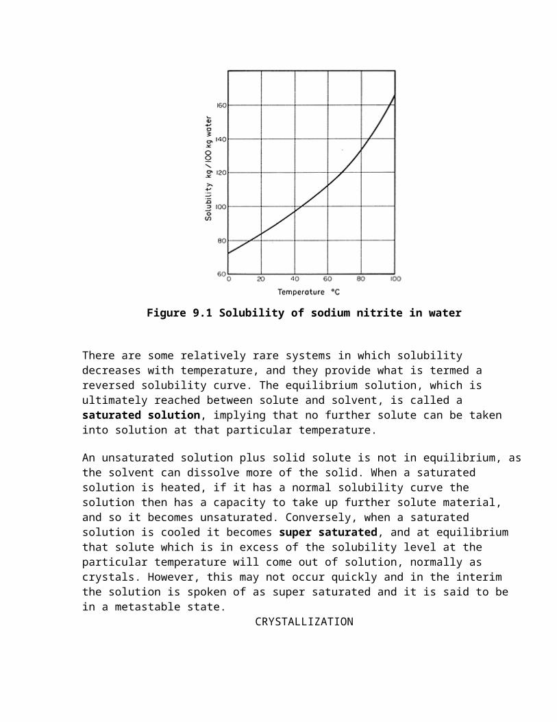
Solubility is a function of temperature and, in most cases, solubility increases with rising temperature. A solubility curve can be drawn to show this relationship, based on the equilibrium concentration in solution measured in convenient units, for example gkg-1, as a function of temperature. Such a curve is illustrated in Fig. 9.1 for sodium nitrite in water.
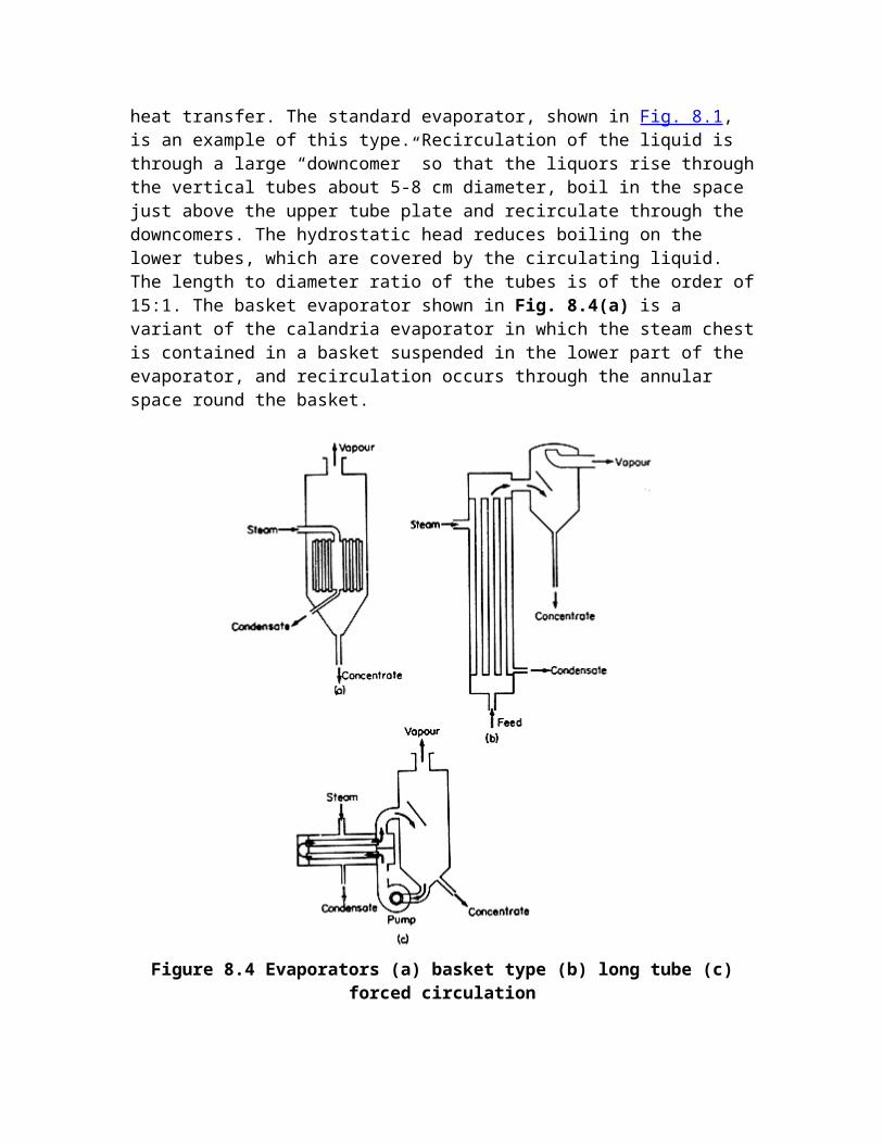
Figure 9.1 Solubility of sodium nitrite in water
There are some relatively rare systems in which solubility decreases with temperature, and they provide what is termed a reversed solubility curve. The equilibrium solution, which is ultimately reached between solute and solvent, is called a saturated solution, implying that no further solute can be taken into solution at that particular temperature.
An unsaturated solution plus solid solute is not in equilibrium, as the solvent can dissolve more of the solid. When a saturated solution is heated, if it has a normal solubility curve the solution then has a capacity to take up further solute material, and so it becomes unsaturated. Conversely, when a saturated solution is cooled it becomes super saturated, and at equilibrium that solute which is in excess of the solubility level at the particular temperature will come out of solution, normally as crystals. However, this may not occur quickly and in the interim the solution is spoken of as super saturated and it is said to be in a metastable state.
CRYSTALLIZATION
Crystallization EquilibriumSolubilityHeat of crystallisation
Rate of Crystal GrowthStage-equilibrium CrystallizationCrystallization Equipment
Crystallization is an example of a separation process in which mass is transferred from a liquid solution, whose composition is generally mixed, to a pure solid crystal. Soluble components are removed from solution by adjusting the conditions so that the solution becomes supersaturated and excess solute crystallizes out in a pure form. This is generally accomplished by lowering the temperature, or by concentration of the solution, in each case to form a supersaturated solution from which crystallization can occur. The equilibrium is established between the crystals and the surrounding solution, the mother liquor. The manufacture of sucrose, from sugar cane or sugar beet, is an important example of crystallization in food technology. Crystallization is also used in the manufacture of other sugars, such as glucose and lactose, in the manufacture of food additives, such as salt, and in the processing of foodstuffs, such as ice cream. In the manufacture of sucrose from cane, water is added and the sugar is pressed out from the residual cane as a solution. This solution is purified and then concentrated to allow the sucrose to crystallize out from the solution.
Crystallization Equilibrium
Once crystallization is concluded, equilibrium is set up between the crystals of pure solute and the residual mother liquor, the balance being determined by the solubility (concentration) and the temperature. The driving force making the crystals grow is the concentration excess (supersaturation) of the solution above the equilibrium (saturation) level. The resistances to growth are the resistance to mass transfer within the solution and the energy needed at the crystal surface for incoming molecules to orient themselves to the crystal lattice.
Solubility and Saturation
Solubility is defined as the maximum weight of anhydrous solute that will dissolve in 100 g of solvent. In the food industry, the solvent is generally water.
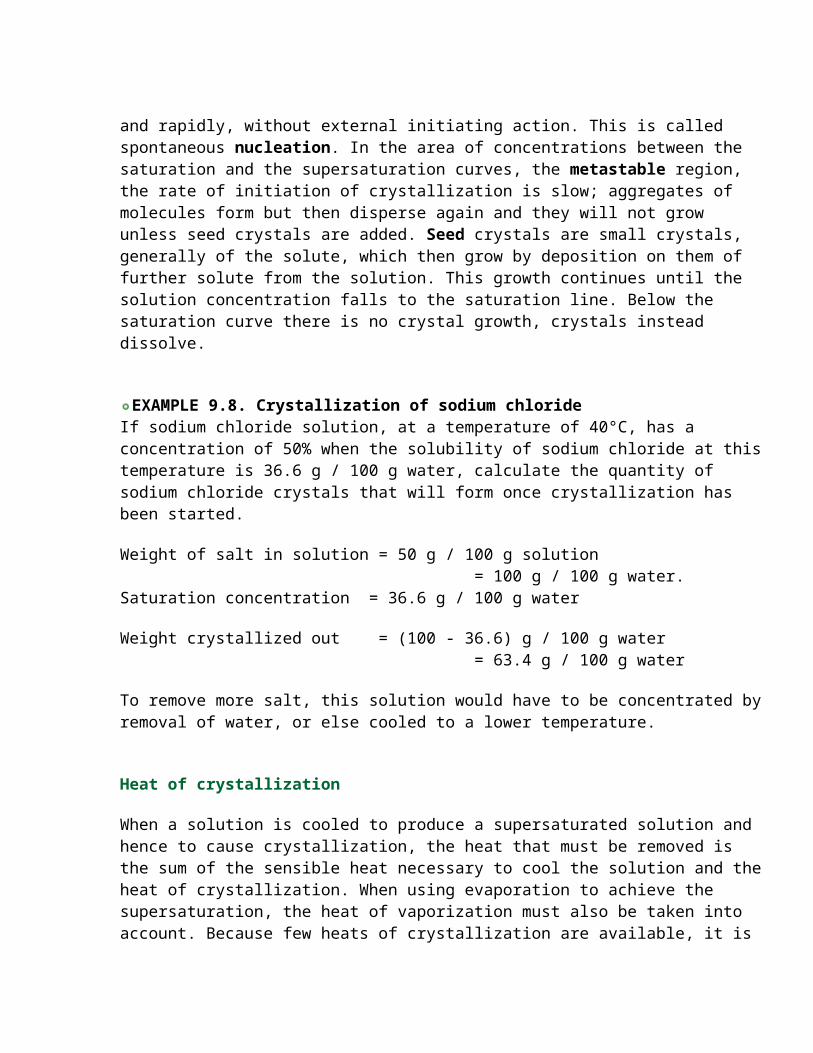
Solubility is a function of temperature. For most food materials increase in temperature increases the solubility of the solute as shown for sucrose in Fig. 9.8. Pressure has very little effect on solubility.
Figure 9.8 Solubility and saturation curves for sucrose in water
During crystallization, the crystals are grown from solutions with concentrations higher than the saturation level in the solubility curves. Above the supersaturation line, crystals form spontaneously and rapidly, without external initiating action. This is called spontaneous nucleation. In the area of concentrations between the saturation and the supersaturation curves, the metastable region, the rate of initiation of crystallization is slow; aggregates of molecules form but then disperse again and they will not grow unless seed crystals are added. Seed crystals are small crystals, generally of the solute, which then grow by deposition on them of further solute from the solution. This growth continues until the solution concentration falls to the saturation line. Below the saturation curve there is no crystal growth, crystals instead dissolve.
EXAMPLE 9.8. Crystallization of sodium chlorideIf sodium chloride solution, at a temperature of 40°C, has a concentration of 50% when the solubility of sodium chloride at this temperature is 36.6 g / 100 g water, calculate the quantity of sodium chloride crystals that will form once crystallization has been started.
Weight of salt in solution = 50 g / 100 g solution = 100 g / 100 g water.Saturation concentration = 36.6 g / 100 g water
Weight crystallized out = (100 - 36.6) g / 100 g water = 63.4 g / 100 g water
To remove more salt, this solution would have to be concentrated by removal of water, or else cooled to a lower temperature.
Heat of crystallization
When a solution is cooled to produce a supersaturated solution and hence to cause crystallization, the heat that must be removed is the sum of the sensible heat necessary to cool the solution and the heat of crystallization. When using evaporation to achieve the supersaturation, the heat of vaporization must also be taken into account. Because few heats of crystallization are available, it is usual to take the heat of crystallization as equal to the heat of solution to form a saturated solution. Theoretically, it is equal to the heat of solution plus the heat of dilution, but the latter is small and can be ignored. For most food materials, the heat of crystallization is positive, i.e. heat is given out during crystallization. Note that heat of crystallization is the opposite of heat of solution. If a material takes in heat, i.e. has a negative heat of solution, then the heat of crystallization is positive. Heat balances can be calculated for crystallization.
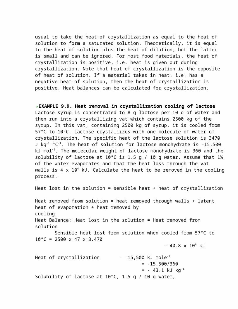
EXAMPLE 9.9. Heat removal in crystallization cooling of lactose Lactose syrup is concentrated to 8 g lactose per 10 g of water and then run into a crystallizing vat which contains 2500 kg of the syrup. In this vat, containing 2500 kg of syrup, it is cooled from 57°C to 10°C. Lactose crystallizes with one molecule of water of crystallization. The specific heat of the lactose solution is 3470 J kg-1 °C-1. The heat of solution for lactose monohydrate is -15,500 kJ mol-1. The molecular weight of lactose monohydrate is 360 and the solubility of lactose at 10°C is 1.5 g / 10 g water. Assume that 1% of the water evaporates and that the heat loss through the vat walls is 4 x 10⁴ kJ. Calculate the heat to be removed in the cooling process.
Heat lost in the solution = sensible heat + heat of crystallization
Heat removed from solution = heat removed through walls + latent heat of evaporation + heat removed by cooling Heat Balance: Heat lost in the solution = Heat removed from solution Sensible heat lost from solution when cooled from 57°C to 10°C = 2500 x 47 x 3.470 = 40.8 x 10⁴ kJ
Heat of crystallization = -15,500 kJ mole-1
= -15,500/360 = - 43.1 kJ kg-1
Solubility of lactose at 10°C, 1.5 g / 10 g water,Anhydrous lactose crystallized out = (8 - 1.5)
= 6.5 g / 10 g water Hydrated lactose crystallized = 6.5 x (342 + 18)/(342) = 6.8 g / 10 g waterTotal water = (10/18) x 2500 kg = 1390 kgTotal hydrated lactose crystallized out = (6.8 x 1390)/10 = 945 kgTotal heat of crystallization = 945 x - 43.1 = 4.07 x 10⁴
Heat removed by vat walls = 4.0 x 10⁴ kJ.Water evaporated = 1% = 13.9 kgThe latent heat of evaporation is, from Steam Tables, 2258 kJ kg-1
Heat removed by evaporation = 13.9 x 2258 kJ = 3.14 x 10⁴ kJ.
Heat balance
40.8 x 10⁴ + 4.07 x 104 = 4 x 10⁴ + 3.14 x 10⁴ + heat removed by cooling.
Heat removed in cooling = 37.7 x 10 4 kJ
Rate of Crystal Growth
Once nucleii are formed, either spontaneously or by seeding, the crystals will continue to grow so long as supersaturation persists. The three main factors controlling the rates of both nucleation and of crystal growth are the temperature, the degree of supersaturation and the interfacial tension between the solute and the solvent. If supersaturation is maintained at a low level, nucleus formation is not encouraged but the available nucleii will continue to grow and large crystals will result. If supersaturation is high, there may be further nucleation and so the growth of existing crystals will not be so great. In practice, slow cooling maintaining a low level of supersaturation produces large crystals and fast cooling produces small crystals.
Nucleation rate is also increased by agitation. For example, in the preparation of fondant for cake decoration, the solution is cooled and stirred energetically. This causes fast formation of nucleii and a large crop of small crystals, which give the smooth texture and the opaque appearance desired by the cake decorator.
Once nucleii have been formed, the important fact in crystallization is the rate at which the crystals will grow. This rate is controlled by the diffusion of the solute through the solvent to the surface of the crystal and by the rate of the reaction at the crystal face when the solute molecules rearrange themselves into the crystal lattice.
These rates of crystal growth can be represented by the equations
dw/dt = KdA(c - ci) (9.13) dw/dt = Ks(ci - cs) (9.14)
where dw is the increase in weight of crystals in time dt, A is the surface area of the crystals, c is the solute concentration of the bulk solution, ci is the solute concentration at the crystal/solution interface, cs is the concentration of the saturated solution, Kd is the mass transfer coefficient to the interface and Ks is the rate constant for the surface reaction.
These equations are not easy to apply in practice because the parameters in the equations cannot be determined and so the equations are usually combined to give:
dw/dt = KA(c - cs) (9.15)
where 1/K = 1/Kd + 1/Ks
or dL/dt = K(c - cs)/s (9.16)since dw = AsdL
and dL/dt is the rate of growth of the side of the crystal and s is the density of the crystal.
It has been shown that at low temperatures diffusion through the solution to the crystal surface requires only a small part of the total energy needed for crystal growth and, therefore, that diffusion at these temperatures has relatively little effect on the growth rate. At higher temperatures, diffusion energies are of the same order as growth energies, so that diffusion becomes much more important. Experimental results have shown that for sucrose the limiting temperature is about 45°C, above which diffusion becomes the controlling factor.
Impurities in the solution retard crystal growth; if the concentration of impurities is high enough, crystals will not grow.
Stage-equilibrium Crystallization
When the first crystals have been separated, the mother liquor can have its temperature and concentration changed to establish a new equilibrium and so a new harvest of crystals. The limit to successive crystallizations is the build up of impurities in the mother liquor which makes both crystallization and crystal separation slow and difficult. This is also the reason why multiple crystallizations are used, with the purest and best crystals coming from the early stages.
For example, in the manufacture of sugar, the concentration of the solution is increased and then seed crystals are added. The temperature is controlled until the crystal nucleii added have grown to the desired size, then the crystals are separated from the residual liquor by centrifuging. The liquor is next returned to a crystallizing evaporator, concentrated again to
produce further supersaturation, seeded and a further crop of crystals of the desired size grown. By this method the crystal size of the sugar can be controlled. The final mother liquor, called molasses, can be held indefinitely without producing any crystallization of sugar.
EXAMPLE 9.10. Multiple stage sugar crystallisation by evaporationThe conditions in a series of sugar evaporators are:
First evaporator: temperature of liquor at 85°C, concentration of entering liquor 65%, weight of entering liquor 5000 kg h-1, concentration of liquor at seeding, 82%.
Second evaporator: temperature of liquor 73°C, concentration of liquor at seeding 84%.Third evaporator: temperature of liquor 60°C, concentration of liquor at seeding 86%.Fourth evaporator: temperature of liquor 51°C, concentration of liquor at seeding 89%.
Calculate the yield of sugar in each evaporator and the concentration of sucrose in the mother liquor leaving the final evaporator.
SUGAR CONCENTRATIONS (g / 100 g water)
On seeding Solubility Weight crystallized
First effect 456 385 71
Second effect 525 330 195
Third effect 614 287 327
Fourth effect 809 265 544The sugar solubility figures are taken from the solubility curve, Fig. 9.7.
MASS BALANCE (weights in kg)Basis 5000 kg sugar solution h-1
Into effect
At seeding
Sugar crystallized
Liquor from effect
First effect
Water 1750 713 - 713
Sugar 3250 3250 506 2744
Second effect
Water 713 522 - 522
Sugar 2744 2744 1018 1726
Third effect
Water 522 279 - 279
Sugar 1726 1726 912 814
Fourth effect
Water 279 99 - 99
Sugar 814 814 539 275Total Sugar - Sugar crystallized 2975 kg : Liquor from effect 275 kg
Yield in first effect 506 kg h-1 506/3250 = 15.6% Yield in second effect 1018 kg h-1 1018/3250 = 31.3% Yield in third effect 912 kg h-1 912/3250 = 28.1% Yield in fourth effect 539 kg h-1 539/3250 = 16.6%Lost in liquor 275 kg h-1 275/3250 = 8.4%
Total yield 91.6%
Quantity of sucrose in final syrup 275 kg/h-1
Concentration of final syrup 73.5% sucrose
Crystallization Equipment
Crystallizers can be divided into two types: crystallizers and evaporators. A crystallizer may be a simple open tank or vat in which the solution loses heat to its surroundings. The solution cools slowly so that large crystals are generally produced. To increase the rate of cooling, agitation and cooling coils or jackets are introduced and these crystallizers can be made continuous. The simplest is an open horizontal trough with a spiral scraper. The trough is water jacketed so that its temperature can be controlled.
An important crystallizer in the food industry is the cylindrical, scraped surface heat exchanger, which is used for plasticizing margarine and cooking fat, and for crystallizing ice cream. It is essentially a double-pipe heat exchanger fitted with an internal scraper, see Fig. 6.3(c). The material is pumped through the central pipe and agitated by the scraper, with the cooling medium flowing through the annulus between the outer pipes.
A crystallizer in which considerable control can be exercised is the Krystal or Oslo crystallizer. In this, a saturated solution is passed in a continuous cycle through a bed of crystals. Close control of crystal size can be obtained.
Evaporative crystallizers are common in the sugar and salt industries. They are generally of the calandria type. Vacuum evaporators are often used for crystallization as well, though provision needs to be made for handling the crystals. Control of crystal size can be
obtained by careful manipulation of the vacuum and feed. The evaporator first concentrates the sugar solution, and when seeding commences the vacuum is increased. This increase causes further evaporation of water which cools the solution and the crystals grow. Fresh saturated solution is added to the evaporator and evaporation continued until the crystals are of the correct size. In some cases, open pan steam-heated evaporators are still used, for example in making coarse salt for the fish industry. In some countries, crystallization of salt from sea water is effected by solar energy which concentrates the water slowly and this generally gives large crystals.
Crystals are regular in shape: cubic, rhombic, tetragonal and so on. The shape of the crystals forming may be influenced by the presence of other compounds in the solution, even in traces. The shape of the crystal is technologically important because such properties as the angle of repose of stacked crystals and rate of dissolving are related to the crystal shape. Another important property is the uniformity of size of the crystals in a product. In a product such as sucrose, a non-uniform crystalline mixture is unattractive in appearance, and difficult to handle in packing and storing as the different sizes tend to separate out. Also the important step of separating mother liquor from the crystals is more difficult.
Cyclones
Cyclones are often used for the removal from air streams of particles of about 10 m or more diameter. They are also used for separating particles from liquids and for separating liquid droplets from gases. The cyclone is a settling chamber in the form of a vertical cylinder, so arranged that the particle-laden air spirals round the cylinder to create centrifugal forces which throw the particles to the outside walls. Added to the gravitational forces, the centrifugal action provides reasonably rapid settlement rates. The spiral path, through the cyclone, provides sufficient separation time. A cyclone is illustrated in Fig. 10.2(a).
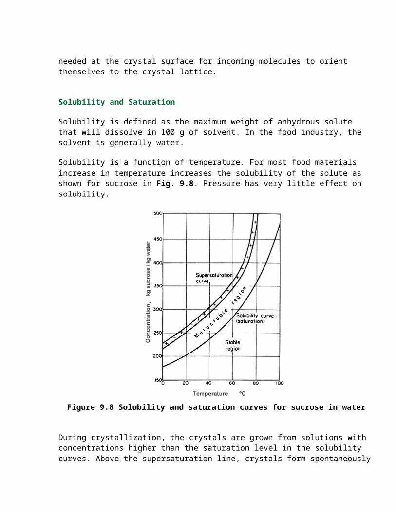
Figure 10.2 Cyclone separator: (a) equipment (b) efficiency of dust collection
Stokes' Law shows that the terminal velocity of the particles is related to the force acting. In a centrifugal separator, such as a cyclone, for a particle, rotating round the periphery of the cyclone: Fc = (mv2)/r (10.4)
where Fc is the centrifugal force acting on the particle, m is the mass of the particle, v is the tangential velocity of the particle and r is the radius of the cyclone.
This equation shows that the force on the particle increases as the radius decreases, for a fixed velocity. Thus, the most efficient cyclones for removing small particles are those of smallest diameter. The limitations on the smallness of the diameter are the capital costs of small diameter cyclones to provide sufficient output, and the pressure drops.
The optimum shape for a cyclone has been evolved mainly from experience and proportions similar to those indicated in Fig. 10.2(a) have been found effective. The efficient operation of a cyclone depends very much on a smooth double helical flow being produced and anything which creates a flow disturbance or tends to make the flow depart from this pattern will have considerable and adverse effects upon efficiency. For example, it is important that the air enters tangentially at the top. Constricting baffles or lids should be avoided at the outlet for the air.
The efficiency of collection of dust in a cyclone is illustrated in Fig. 10.2(b). Because of the complex flow, the size cut of particles is not sharp and it can be seen that the percentage of entering particles which are retained in the cyclone falls off for particles below about 10 m diameter. Cyclones can be used for separating particles from liquids as well as from gases and also for separating liquid droplets from gases.
SwensonForced-CirculationEvaporatorAs the name implies, the liquor in a forced-circulation evaporator is pumped through the tubes to minimize tube scaling or salting when precipitates are formed during evaporation. A Swenson forced-circulation evaporator(with a submerged inlet) complete with a single-passvertical heat exchanger, elutriating leg, cyclone, and topmounted barometric condenser is shown in Fig. 8.Slurry is pumped from the bottom cone of the vapor body through the tubes of the vertical heat exchanger, where heat is added, and back into the vapor body whereevaporation occurs. Sufficient slurry height (submergence) is maintained above the tangential inlet on the vapor body and above the top tubesheet of the heat exchanger to suppress mass boiling in the inlet and prevent surface (local) boiling on the tube surface. This isnecessary to preclude salt precipitation on the tangential inlet and tubes. A high circulation rate is provided for adequate tube velocity to achieve good heat transfer. Therefore, lower slurry temperature rises are assured which minimize supersaturation of the solution. A sufficient quantity of salt crystals is suspended in the circulating system to provide seed crystals in the boiling zone for salt growth. Adherence to these basic principles of crystallizationresults in coarse crystals and minimal wall and tube salting, so less equipment washing is required. This conserves energy because less steam is required to boil wash water and this increases on-stream time for th evaporator. The circulating pump is usually of the axial-flow,single-elbow design, well-suited for the high flow rates and low pressure drops in Swenson-designed circulating systems. These heavy duty pumps operate at low speeds,which reduce maintenance and minimize mechanical attrition of the salt crystals.Circulating piping interconnects the vapor body, the heat exchanger and the pump. Conical liquor chambersprovide gradual, low pressure drop transitions from the circulating piping to the tube bundle which is particularly important for the establishment of uniform feed to the tubes. To provide for thermal expansion withoutexpansion joints, the circulating pump base is springmounted.As an alternative, the entire pump may be hung from the circulating piping.
The tangential inlet provides excellent mixing of slurry in the vapor body because of the circular motion it creates. Secondary vertical currents are also generated mixing body slurry with the hotter slurry entering the vapor body to reduce the degrees of flash. This agitationminimizes salt buildup on the bottom cone of the vapor body. A swirl beaker is provided in the circulating slurry outlet.The vapor body is conservatively designed both in diameter and height. It is important to have an adequate free space above the liquor level to allow the liquor droplets entrained in the vapor leaving the boiling surface to reach equilibrium and return by gravity to the circulatingslurry. The large diameters result in low vapor velocities which minimize entrainment and provide adequate retention time for salt growth. A mesh-type entrainment separator may be installed in the upper portion of the vapor body to reduce solids carryover to normally less than 50 parts per million parts of vapor. Swenson’s sturdy mesh container design has virtually eliminated mesh falls into the vapor body. Other types of entrainment separators are also available. The elutriating leg, attached to the bottom cone of the vapor body, is a convenient device for thickening the slurry it receives from the vapor body and for salt crystal washingand classification - Slurry enters the top of the leg through a unique slurry-inlet device, which improves washing efficiency by reducing agitation in the leg.* Salt crystals are fluidized and washed in the leg with a portion of the feed liquor which enters the bottom cone and is distributedwith a perforated, dished head. Smaller crystals are washed into the vapor body for additional growth and the largercrystals are discharged from a connection near the bottom of the leg.A Swenson-designed, low-pressure-drop liquid cyclone is sometimes used to clarify liquor discharged from the evaporator. The driving force is the pressure drop across the circulating pump. Thickened slurry is returnedthrough a wide-open cyclone underflow connection to the circulating piping before the pump suction. Another Swenson innovation is the direct-contactcondenser mounted on the vapor body. A short piece of vertical pipe connects the vapor body with the condenser tominimize piping and pressure drop. This design also eliminates structural steel for support of a separate condenser. For cooling tower applications, the hotwell is elevated to permit gravity flow of water from the hotwell to the top of the cooling tower, thus eliminating the need for apump. A Swenson forced-circulation evaporator with horizontal heat exchanger and a top-mounted stripping column is shown in Fig. 9. Reflux liquid is introduced on the top tray of the column to strip one or more compounds from the water vapor. Stripping columns are used forspecial applications and are provided either integral with the evaporator or as a separate column. The columns are for the recovery of valuable components from the water vapor and for the reduction of volatile pollutants. Swenson has supplied stripping columns with ballast and valve trays for caprolactam and boric acid service. Spray columns havebeen used for the recovery of fluorine generated along withthe vapor during the concentration of phosphoric acid.