Embed Size (px)
Citation preview
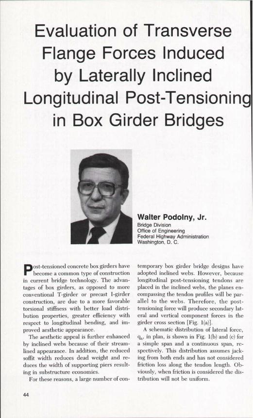
Evaluation of TransverseFlange Forces Induced
by Laterally InclinedLongitudinal Post-Tensionin
in Box Girder Bridges
Walter Podolny, Jr.Bridge DivisionOffice of EngineeringFederal Highway AdministrationWashington, D. C.
Post-tensioned concrete box girders havebecome a common type of construction
in current bridge technology. The advan-tages of box girders, as opposed to moreconventional T-girder or precast I-girderconstruction, are due to a more favorabletorsional stiffness with better load distri-bution properties, greater efficiency withrespect to longitudinal bending, and im-proved aesthetic appearance.
The aesthetic appeal is further enhancedby inclined webs because of their stream-lined appearance. In addition, the reducedsoffit width reduces dead weight and re-duces the width of supporting piers result-ing in substructure economies.
For these reasons, a large number of con-
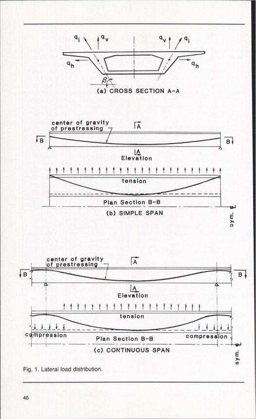
temporary box girder bridge designs haveadopted inclined webs. However, becauselongitudinal post-tensioning tendons areplaced in the inclined webs, the planes en-compassing the tendon profiles will be par-allel to the webs. Therefore, the post-tensioning force will produce secondary lat-eral and vertical component forces in thegirder cross section [Fig. 1(a)].
A schematic distribution of lateral force,q, in plan, is shown in Fig. 1(b) and (c) fora simple span and a continuous span, re-spectively. This distribution assumes jack-ing from both ends and has not consideredfriction loss along the tendon length. Ob-viously, when friction is considered the dis-tribution will not be uniform.
44
The magnitude of transverse secondaryforces or stresses could be such as to pro-duce cracking in the box girder flanges (Fig.2). Cracking has been observed in somebridges which can wholly or partially be at-tributed to the effect of inclined tendon pro-files. ` Transverse stresses are introduced intobox girder bridges from dead and live loads,torsion, thermal gradient, and other factors.However, this paper will only consider thelateral effects induced in the flanges as aresult of longitudinal prestressing in lat-erally inclined planes.
TENDON PROFILEThe tendon profile is generally presented
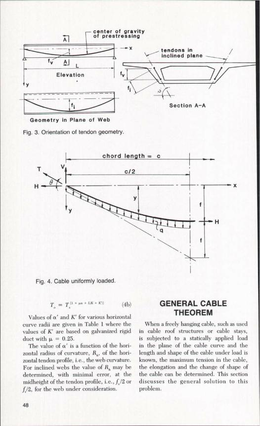
in design drawings on a vertical elevation ofthe girder (Fig. 3). The tendon offset or sagis then the value off. However, where thetendons are placed in an inclined plane, thegeometry of the tendon profile must be de-termined with respect to that inclined planeto reflect the actual friction losses.
Tendon offset in the inclined plane (seeFig. 3) is determined as:
f. = f. /sin R (I)
from which the tendon radius of curvature,R;, in the inclined plane, can be determinedfrom:
R. = (4f2 + c2)/8f (2)
where c is the chord length of the profilecurve. In the case of a simple span, the chordlength is equal to the span length.
SynopsisA large number of contemporary
box girders have a trapezoidal crosssection. Because the webs are lat-erally inclined, the longitudinal post-tensioning profile plane is parallel tothe webs. Therefore, the post-ten-sioning force will produce secondarylateral and vertical component forcesin the cross section. This paper con-siders only the lateral effects inducedin the flanges as a result of longitu-dinal prestressing in laterally inclinedplanes.
With the possible exception of ex-ternal tendons, the stresses inducedin the flanges by these secondaryforces are generally small when takenalone. However, when superimposedupon other stresses, or if other poten-tial cracking mechanisms are present,distress in the form of cracking maybe precipitated. These lateral forceshave been wholly or partially attrib-uted to cracking in some bridges.
The proposed design procedure isillustrated with two numerical exam-ples, one for a simple span girder andthe other for a continuous girder to-gether with the special case of exter-nal tendons.
T,,=T (1 + KL + µa) (3b)TENDON FORCE AFTER
FRICTION LOSSHaving determined the tendon geometry
with respect to the inclined plane, the ten-don force after friction loss can be deter-mined in a conventional manner from thefollowing equation:'
To = T,e°"'' "") (3a)
When the expression (KL + µa) :5 0.3,the following equation is used:
whereT^ = steel stress or force at jacking
endTx = steel stress or force at any
point xe = base of Naperian logarithmsK = friction wobble coefficient per foot
of prestressing tendonL = length of prestressing steel
element from jack end to point xµ = friction curvature coefficienta = total angular change of
PCI JOURNAL/January-February 1986 45
Qi Q" Q" /
4 h ^ Qh
(a) CROSS SECTION A-A
center of gravityof prestressing
LElevation
tension
Plan Section B-B
(b) SIMPLE SPAN
c7
1 B
Elevation
tt?t??11IttttItII II
c mpression Plan Section B-B
(c) CONTINUOUS SPAN
corn prea TI on
Ey
Fig. 1. Lateral load distribution.
46
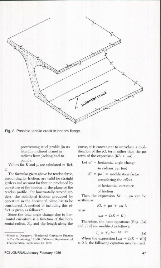
Fig. 2. Possible tensile crack in bottom flange.
prestressing steel profile (in itslaterally inclined plane) inradians from jacking end topoint x
Values for K and µ are tabulated in Ref.2.
The formulas given above for tendon force,accounting for friction, are valid for straightgirders and account for friction produced bycurvature of the tendon in the plane of thetendon profile. For horizontally curved gir-ders, the additional friction produced bycurvature in the horizontal plane has to beconsidered. A method of including this ef-fect is given as follows:*
Since the total angle change due to hor-izontal curvature is a function of the hori-zontal radius, R, , , and the length along the
* Memo to Designers, "Horizontal Curvature Frictionin Post-Tensioning," 11-30, California Department ofTransportation, September 24, 1970.
curve, it is convenient to introduce a mod-ification of the KL term rather than the µaterm of the expression (KL + µa).
Let a' = horizontal angle change
in radians per foot
K' = µa' = modification factor
considering the effect
of horizontal curvature
of frictionThen the expression KL + µa can he
written as:
KL+µa+µa'Lor as:
µa+ L(K +K')
Therefore, the basic equations [Eqs. (3a)and (3b)] are modified as follows:
T,, = T,e [4. + UK + K')1 (4a)When the expression [µa + L(K + K')]0.3, the following equation may be used:
PCI JOURNAL/January-February 1986 47
center of gravityAl of prestressing
fv J L — CElevation fv
Y ,\
fi
tendons ininclined plane
Section A–A
Geometry in Plane of Web
Fig. 3. Orientation of tendon geometry.
chord length = c
Tc/2
H
1 Yf
Y
H
Q
Fig. 4. Cable uniformly loaded.
T = T=« + + uK + K•)] (4b)
Values of a' and K' for various horizontalcurve radii are given in Table 1 where thevalues of K' are based on galvanized rigidduct with µ = 0.25.
The value of a' is a function of the hori-zontal radius of curvature, R, of the hori-zontal tendon profile, i.e., the web curvature.For inclined webs the value of R, may bedetermined, with minimal error, at themidheight of the tendon profile, i.e., f. /2 orf /2, for the web under consideration.
GENERAL CABLETHEOREM
When a freely hanging cable, such as usedin cable roof structures or cable stays,is subjected to a statically applied loadin the plane of the cable curve and thelength and shape of the cable under load isknown, the maximum tension in the cable,the elongation and the change of shape ofthe cable can be determined. This sectiondiscusses the general solution to thisproblem.
48
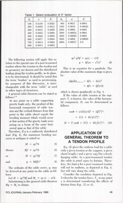
Table 1. Select evaluation of K' factor
a' K' R,, a' K'
100 0.0100 0.0025 900 0.0011 0.0003200 0.0050 0.0012 1000 0.010 0.00025300 0.0033 0.0008 2000 0.0005 0.0001400 0.0025 0.0006 3000 0.00033 0.0001500 0.0020 0.0005 4000 0.000025 0.0001600 0.0017 0.0004 5000 0.0002 0.00005700 0.0014 0.0004 6000 0.00017 0.0800 0.0013 0.0003
The following section will apply this so-lution to the special case of a post-tensionedtendon where the tension in the tendon andits geometry are known and the distributedloading along the tendon profile, in its plane,is to be determined. It should be noted thatthe term "tendon" as used in prestressing,for purposes of this discussion, is inter-changeable with the term "cable" as usedin other types of structures.
A general cable theorem can be stated asfollows:''°
At any point on a cable supportinggravity loads only, the product of thehorizontal component of cable ten-sion and the vertical distance from thatpoint to the cable chord equals thebending moment which would occurat that section if the gravity loads wereacting on a beam of the same hori-zontal span as that of the cable.
Therefore, if q is a uniformly distributedload (Fig. 4), the maximum bending mo-ment at midspan is stated as:
M = qc2/8 (5)
Hence Hf = gc2/8 (6)
or H = qc2/8f (7)
and q = 8Hf/c2 (8)
The ordinate of the cable curve, y, maybe derived at any point on the cable as fol-lows:
Let H = gc2l8f and M, = qx (c - x)/2.
Substituting in the general cable theoremHy = M. to obtain:
qc2 y/8f = qx(c - x)/2y = 4f(cx - x2)/c2 (9)
This is an equation for a parabola. Theabsolute value of the maximum slope is givenby:
(dy/dx)=_p, =_, = 4f(c - 2x)/c2
= 4f/c = 2fl(c/2)
which is shown graphically in Fig. 4.If the value of cable tension at the sup-
port, T, is known, the value of the horizon-tal component, H, can be determined asfollows:
cosO = (c/2)/[(c/2)2 + (2f)21'2
= 1/[1 + 16(flc)2]'/2
H = T cos8 = Till + 16(f/c) 21 1,2 (10)
APPLICATION OFGENERAL THEOREM TO
A TENDON PROFILEEq. (8) gives the uniform load for a cable
with a given tension at the support, a givenchord length c and a given sag f for a freelyhanging cable. In a post-tensioned tendonthe cable is acted upon by friction. There-fore, the load q for a post-tensioned tendonwill not be uniform, as depicted in Fig. 4,but will vary along the cable.
Consider the condition depicted in Fig.5 whereby the tendon force, Tr, at any pointx is determined considering the effects offriction from Eqs. (3) or (4).
PCI JOURNAL/January-February 1986 49
Then from Eq. (9):
y = 4f(cx — x2)/c2
The cable offset, f', with respect to thecoordinates x and y is:
f' = f — y = f — [4f(cx — x2)/c2]
The chord length c depicted in Fig. 4 inrelation to the cross hatch area in Fig. 5becomes c' = c — 2x.
The term f/c in Eq. (10) with relation toany point x becomes:
f'lc' = {f — [4f(cx — x2)/c2]}/(c — 2x)= f(c — 2x)/c2
and
(f'/c')- = f (c — 2x)2/c'
From Eq. (10):
Tx, = Tx/{1 + [16f2 (c — 2x)2/c4 ]}''2 (11)
From Eq. (8):
qz = 8T,hf'l(c')2
= 8fT,/[c' + 16f 2 (c — 2x)2]''2 (12)
For the case when x = c/2:
qx = 8fT.,/(c4)"z = 8f TJC2(13)
which corresponds with Eq. (8).For an inclined plane, the term f (see
Fig. 3) would be substituted for the f termin Eqs. (11), (12) and (13).
LATERAL LOADINDUCED IN FLANGES
Having determined the distribution of loadalong the tendon profile and in the inclinedplane, the horizontal component can be de-termined at any point x by:
q=h = qx; cos(3 (14)
where 13 is the angle of inclination of thetendon profile (Fig. 3).
With the web acting as a beam fixed atthe top and bottom flanges, the distribution
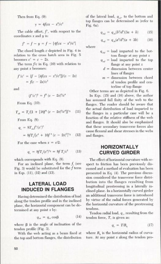
of the lateral load, q,,, , to the bottom andtop flanges can be determined as (refer toFig. 6a):
q,,f = gxh(b2/d3)(3a + b) (15)
q,.,f = q(a'ld3)(a + 3b) (16)
whereq,,f = load imparted to the bot-
tom flange at any point xq, .f = load imparted to the top
flange at any point xd = dimension between center
lines of flangesm = dimension between chord
of tendon profile and cen-terline of top flange
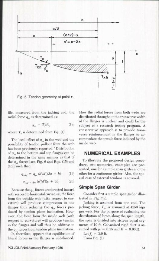
Other terms are as depicted in Fig. 6.In Eqs. (15) and (16) above, the author
has assumed full fixity of the web to theflanges. The reader should be aware thatthe actual distribution of load imparted tothe flanges in a particular case will be afunction of the relative stiffness of the weband flanges. It should also be emphasizedthat these secondary transverse forces alsocause flexural and shear stresses in the websand flanges.
HORIZONTALLYCURVED GIRDER
The effect of horizontal curvature with re-spect to friction has been previously dis-cussed and a method of evaluation has beenpresented in Eq. (4). The previous discus-sion considered the transverse force distri-bution into the flanges resulting fromlongitudinal prestressing in a laterally in-clined plane. In a horizontally curved girderan additional transverse force is introducedby virtue of the radial forces generated bythe horizontal curvature of the prestressingtendons.
Tendon radial load, q, resulting from thetendon force, T, is given as:
q, = T/R,,(17)
where Rh is the horizontal radius of curva-ture. At any point x along the tendon pro-
50
C
c/2
X (c/2)–x
c'= c-2x
Tx
Tx hx
Y
X
Fig. 5. Tendon geometry at point x.
file, measured from the jacking end, theradial force q ,.Y is determined as:
q„ = Ti/Rh (18)
where T , is determined from Eq. (4).
The local effect of q , in the web and thepossibility of tendon pullout from the webhas been previously reported.'' Distributionof q ,. to the bottom and top flanges can bedetermined in the same manner as that of
the q [see Fig. 6 and Eqs. (15) and(16)] such that:
= q,., (b2/&)(3a + b) (19)
q ,., ,1 = qn (a21d3)(a + 3b) (20)
Because the q,. . forces are directed inwardwith respect to horizontal curvature, the forcefrom the outside web (with respect to cur-vature) will produce compression in theflanges thus reducing the q pro-duced by tendon plane inclination. How-ever, the force from the inside web (withrespect to curvature) will produce tensionin the flanges and will thus be additive tothe q ,. ,, forces from tendon plane inclination.
It, therefore, appears that equilibrium oflateral forces in the flanges is unbalanced.
How the radial forces from both webs aredistributed throughout the transverse widthof the flanges is unclear and could be thesubject of a research testing program. Aconservative approach is to provide trans-verse reinforcement in the flanges to ac-commodate the tensile force induced by theinside web.
NUMERICAL EXAMPLESTo illustrate the proposed design proce-
dure, two numerical examples are pre-sented, one for a simple span girder and theother for a continuous girder. Also, the spe-cial case of external tendons is covered.
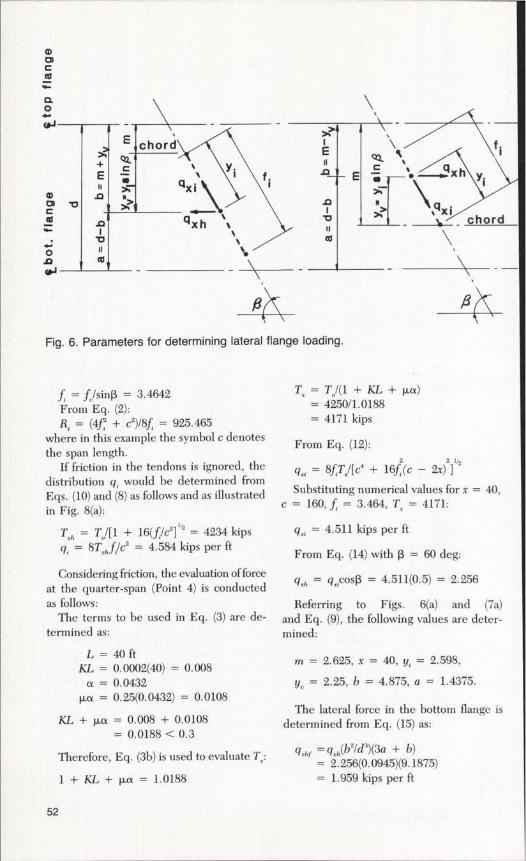
Simple Span GirderConsider first a simple span girder illus-
trated in Fig. 7(a).Jacking is assumed from one end. The
jacking force, T0 , is assumed at 4250 kipsper web. For the purpose of evaluating thedistribution of forces along the span length,the span is divided into sixteen equal seg-ments of 10 ft. Galvanized rigid duct is as-sumed with µ = 0.25 and K = 0.0002.
Let f , = 3.0 ft.From Eq. (1):
PCI JOURNAL/January-February 1986 51
mac
aO
chord
+E
c^
ua
^,.^
w i
O ^^
T)
n£f'q —: —4xh yi \
.0 I h q
qxh ^^ chord
Fig. 6. Parameters for determining lateral flange loading.
f. = f /sin[3 = 3.4642From Eq. (2):R = (4f + c 2')18f, = 925.465
where in this example the symbol c denotesthe span length.
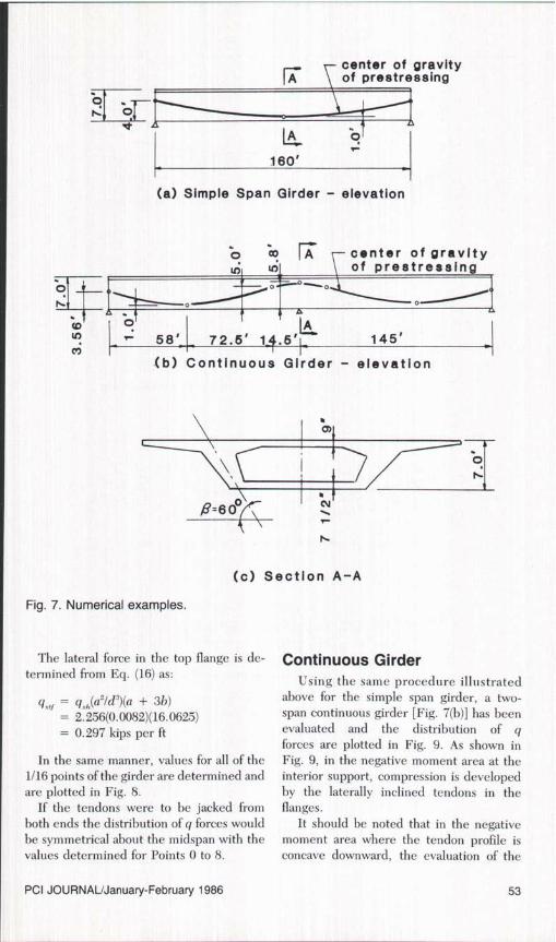
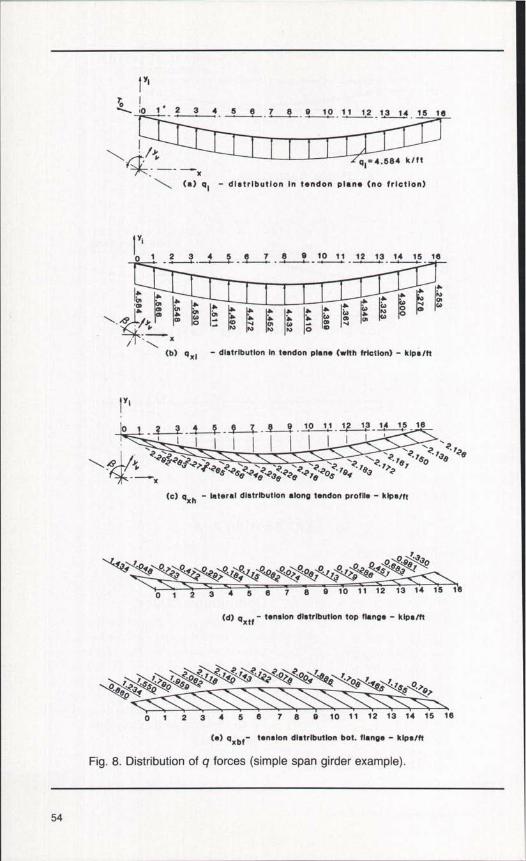
If friction in the tendons is ignored, thedistribution q, would be determined fromEqs. (10) and (8) as follows and as illustratedin Fig. 8(a):
Tx;, = T,/[ 1 + 16(f /c2 ] 112 = 4234 kipsq; = 8T, fIc2 = 4.584 kips per ft
Considering friction, the evaluation of forceat the quarter-span (Point 4) is conductedas follows:
The terms to be used in Eq. (3) are de-termined as:
L = 40 ftKL = 0.0002(40) = 0.008
a = 0.0432µa = 0.25(0.0432) = 0.0108
KL +µa=0.008+0.0108= 0.0188 < 0.3
Therefore, Eq. (3b) is used to evaluate Tx:
1+KL +µa= 1.0188
Tx=T0/(1+KL +µa)= 4250/1.0188= 4171 kips
From Eq. (12):2 21/2
qx = 8fTx/[c4 + 16f (c — 2x) ]
Substituting numerical values for x = 40,c = 160, f = 3.464, Tx = 4171:
q ,, = 4.511 kips per ft
From Eq. (14) with (3 = 60 deg:
gxti = q,5cos(3 = 4.511(0.5) = 2.256
Referring to Figs. 6(a) and (7a)and Eq. (9), the following values are deter-mined:
m = 2.625, x = 40, y; = 2.598,
yL = 2.25, b = 4.875, a = 1.4375.
The lateral force in the bottom flange isdetermined from Eq. (15) as:
qx^r = g (b2/d3)(3a + b)= 2.256(0.0945)(9.1875)= 1.959 kips per ft
52
center of gravity
FA of prestressing
0 0
LA o
160'
(a) Simple Span Girder – elevation
o ao rA center of gravityof prestressingt oI
M - 58'7 2.6' 14.5' 145'
(b) Continuous Girder - elevation
rn
(c) Section A-A
Fig. 7. Numerical examples.
The lateral force in the top flange is de-termined from Eq. (16) as:
q ,r = q(a2/d')(a + 3h)= 2.256(0.0082)(16.0625)= 0.297 kips per ft
In the same manner, values for all of the1/16 points of the girder are determined andare plotted in Fig. 8.
If the tendons were to be jacked fromboth ends the distribution of q forces wouldbe symmetrical about the midspan with thevalues determined for Points 0 to 8.
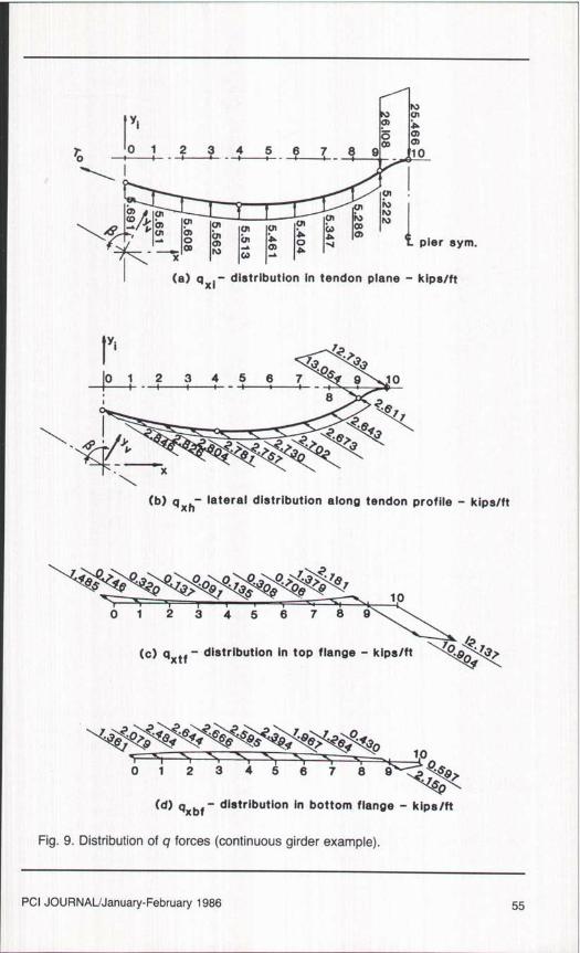
Continuous GirderUsing the same procedure illustrated
above for the simple span girder, a two-span continuous girder [Fig. 7(h)] has beenevaluated and the distribution of qforces are plotted in Fig. 9. As shown inFig. 9, in the negative moment area at theinterior support, compression is developedby the laterally inclined tendons in theflanges.
It should be noted that in the negativemoment area where the tendon profile isconcave downward, the evaluation of the
PCI JOURNAL/January-February 1986 53
I y'7•010 1 2 3 4 5 8 7 B 9 10 11 12 13 14 15 18
\ I /Yq1=4.584 k/tt
(a) q l - distribution In tendon plane (no friction)
IN
lYi
0 12 3 4 5 6 7 89 10 11 12 13 14 15 18
A A 1 A A
A IA A A r^ ^ Iq\ ^ ^ I^ Lw j ^ A A A A W j I^' Iw"'^. ^ LL/Y I_o. ^ a ^ ^ m m m II"""- \ x N N fT (J V
N N O
(b) q xl - distribution In tendon plans (with friction) - kips/ft
I
Yl
0 1 10 11 13 1s-18
\?2g?? 2 ^ ^? / ^? /S 73e B^I ^ c' 63 2Y4"•2es ? B *^ ^3^ 2e??'^?OS )g ? /93 2 )Y2 B7 Ox
(c) qxh - lateral distribution along tendon profile - kips/ft
* 704e 0, 3 4' O?O'O /e^ S\OOe/O'/3 ''\e 4S\;9g; 30
0 1 2 3 4 5 6 7 8 9 10 11 12 13 14 15 16
(d) g xtf - tension distribution top flange - kips/ft
O eeO 3*SS/ g0 B 80 2 / /e /4^ /'3 / ?O'er 009' a ''Oe S /' /SS\^
0 1 2 3 4 5 8 7 8 9 10 11 12 13 14 15 18
(e) gxbf- tension distribution bot. flange - kips/ft
Fig. 8. Distribution of q forces (simple span girder example).
54
yl
r '0 1 2 3 4 5 6 7 8 9 ~ 100
^ NU U NU U U CO
-^ U U U U A I^ U pier sym.x l N (^ r
(a) q Xi - distribution In tendon plane - kips/ft
I0 1 2 3 4 5 6 7 S 9 10
8 ?2e r
? 43
(b) q x h lateral distribution along tendon profile - kips/ft
¢eS 0090 7` S 3 O,OS r8 ^ 10
0 1 2 3 4 5 6 7 8 9
(c) gxtf - distribution in top flange - kips/ft
O,9 4S4 e44 Sss SAS 4'^e^r?s4 430 100 1 2 3 4 5 6 7 8 9 ^a Sgt
(d) gxbf - distribution In bottom flange - kips/ft
Fig. 9. Distribution of q forces (continuous girder example).
PCI JOURNAL/January-February 1986 55
16'-4" 9' box girder
6o aa^sl Yv y / ya
Ig^^on
0^^a(a)
0
R^ ., L R lv y
(c)
rn
a0
N
II
Rlvh I oa= 0.722'
(e)
R/v
R \Ivh
(d)
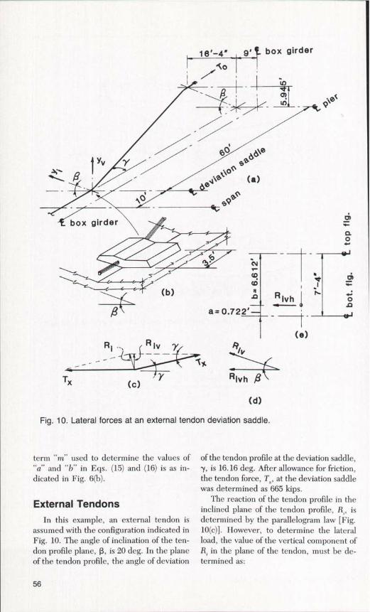
Fig. 10. Lateral forces at an external tendon deviation saddle.
term "m" used to determine the values of"a" and "b" in Eqs. (15) and (16) is as in-dicated in Fig. 6(b).
External TendonsIn this example, an external tendon is
assumed with the configuration indicated inFig. 10. The angle of inclination of the ten-don profile plane, R, is 20 deg. In the planeof the tendon profile, the angle of deviation
of the tendon profile at the deviation saddle,y, is 16.16 deg. After allowance for friction,the tendon force, Tx, at the deviation saddlewas determined as 665 kips.
The reaction of the tendon profile in theinclined plane of the tendon profile, R; , isdetermined by the parallelogram law [Fig.10(c)]. However, to determine the lateralload, the value of the vertical component ofR; in the plane of the tendon, must be de-termined as:
56
160
140
120
11.10.'C,,a
N 80
NO1
60LL
40
20
IC
girder
of girder
0° 15° 30° 45° 60° 75° 900
Inclination of Web (fi)
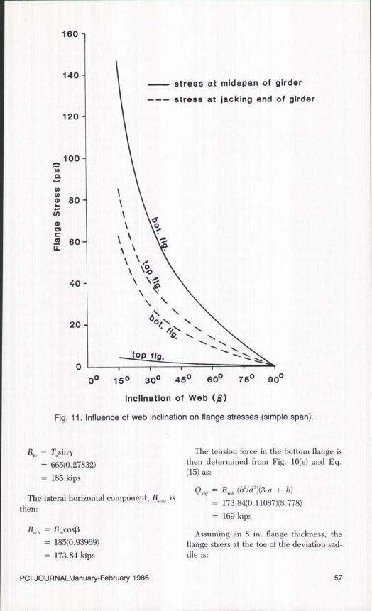
Fig. 11. Influence of web inclination on flange stresses (simple span).
R,^ = T,siny
= 665(0.27832)
= 185 kips
The lateral horizontal component, R,,, ,, , is
then:
R; _, = Rcos(3
= 185(0.93969)
= 173.84 kips
The tension force in the bottom flange isthen determined from Fig. 10(e) and Eq.(15) as:
Q.rbr = R,.,h (b21d3)(3 a + b)
= 173.84(0.11087)(8.778)
= 169 kips
Assuming an 8 in. flange thickness, theflange stress at the toe of the deviation sad-dle is:
PCI JOURNAL/January-February 1986 57
f = 169000/(42 x 8)= 503 psi
If a 5500 psi concrete with a strength atstressing of 4000 psi is assumed, the re-spective theoretical cracking stresses are 556and 474 psi, respectively.
INFLUENCE OFLATERAL INCLINATIONOF TENDON PROFILE
The above examples were evaluated witha tendon profile lateral angle of inclination,13, equal to 60 deg in the first two cases and20 deg in the last case. To determine theinfluence of this parameter, stresses wereevaluated for the case of the simple spangirder at midspan and at the end of the gir-der by varying the angle of inclination 13.The plot shown in Fig. 11 indicates that thereis an approximate 70 percent increase of lat-eral force (or stress) when the angle of in-clination is decreased from 60 to 45 deg.Similarly, there is an approximate 195 per-cent increase in stress when the angle de-creases from 60 to 30 deg.
Therefore, this plot verifies the obviousconclusion that the tension induced in theflanges increases from the one extreme case,where the stress is zero when the web isvertical (an angle of web inclination withrespect to the horizontal of 90 deg) to a max-imum as the angle of inclination approachesa horizontal condition.
This indicates, as would be expected, thatat midspan, because of the close proximityof the tendon profile to the bottom flange,the stress in the bottom flange is of a largermagnitude than that for the top flange. Atthe ends of the girder, because of the prox-imity of the tendon profile to the top flange,the stress is of a larger magnitude in the topflange than the bottom flange.
Usually, in current practice, the angle ofinclination of tendon profiles is at or near60 deg. The author is aware of two projectsin the United States where in one case theangle of inclination is 40 deg and in the othercase 20 deg. In both cases external tendonsare used.
DESIGNRECOMMENDATIONS
1. At the very least, the forces developedby draped longitudinal tendons embeddedin inclined webs should be evaluated forthose designs where the angle of inclinationis outside the limits of the current state ofthe art, i.e., angles of inclination of approx-imately 45 deg or less. Certainly, the con-dition at deviation saddles for externaltendons should be investigated.
2. From the limited study conducted inthis paper it appears that the effect of fric-tion on the lateral forces is not a significantfactor. Therefore, for simplification of thetransverse cross section analysis, friction maybe ignored on the conservative side.
3. Secondary moments and shears in theflanges and webs resulting from the forcesinduced by laterally inclined longitudinalpost-tensioning, which may be of signifi-cance, have not been evaluated in this pa-per. However, a method of evaluating thelateral force induced by inclined post-ten-sioning tendons has been presented. Oncethese forces are determined they can be in-cluded with other loads in the conventionalframe analysis of the cross section.
4. Obviously, where secondary stressesproduced by laterally inclined longitudinalpost-tensioning become excessive in them-selves or in conjunction with other stresses,the amount and distribution of transversereinforcing steel and/or transverse pres-tressing will require evaluation.
CONCLUSIONLongitudinal post-tensioning in a laterally
inclined plane will produce lateral forces inthe flanges of box girders. The magnitudeof these lateral forces is a function of thefollowing parameters: (1) prestress force, (2)tendon profile and (3) angle of inclination ofthe tendon profile plane.
For the case of draped tendons within in-clined webs, the maximum tensile force inthe bottom flange is located at the low pointof the tendon profile, decreasing toward theend of the girder or a tendon inflection point.
58
Maximum tensile force in the top flange isat either end of the girder or a tendon in-flection point. In the case of external ten-dons, it is obvious that the maximum tensileforce will occur in the bottom flange at thelocation of the deviation saddle and will beof a larger magnitude (concentrated force)than for the embeded draped tendon (dis-tributed force).
Depending upon the parameters men-tioned above, the magnitude of lateral stressinduced in the flanges are, in general, neg-ligible when taken alone. The possible ex-ception may be for the case of externaltendons. However, when these stresses aresuperimposed on other primary stresses(dead and live load, torsion, thermal gra-dient, etc.) and other secondary transversestresses that may have been considered (orignored) it may be that the tensile capacityof the concrete will be exceeded resulting
in cracking.Or, if other potential cracking mecha-
nisms are present (see Ref. 5) they may beaggravated to a point where cracking istriggered. At least one reference' in theliterature has reported the observation thatlateral forces produced by laterally in-clined longitudinal tendons can be whollyor partially attributed to cracking in somebridges.
It should be noted that the evaluation oflateral forces presented in this paper havebeen based upon the assumption of full fix-ity of the web to the flanges, the actual dis-tribution of load imparted to the flanges willbe a function of the relative stiffness of theweb and flanges. Further, this evaluationhas not considered the effects of anchorageseating, overstressing and subsequent re-lease-back, presence of diaphragms, andtime-dependent losses.
PCI JOURNAL/January-February 1986 59
REFERENCES1. Leonhardt, F., and Lippoth, W.,"Lessons from
Damage to Prestressed Concrete Bridges,"Benton- and Stahlbetonbau, No. 10, October1971.
2. Standard Specifications for Highway Bridges,13th Edition, American Association of StateHighway and Transportation Officials, 1983.
3. Wilbur, J. B., and Norris, C. H., ElementaryStructural Analysis, Chapter 11, McGraw-HillBook Co., Inc., New York, N.Y., 1948.
4. Scalzi, J. B., Podolny, W., Jr., and Teng, W.C., "Design Fundamentals of Cable RoofStructures," ADUSS 55-3580-01, United StatesSteel Corporation, Pittsburgh, Pennsylvania,October 1969.
5. Podolny, W., Jr., "The Cause of Crackingin Post-Tensioned Concrete Box GirderBridges and Retrofit Procedures," PCI JOUR-NAL, V. 30, No. 2, March-April 1985, pp. 82-139.
APPENDIX-NOTATIONa = dimension from cable profile to
center of bottom flangeb = dimension from cable profile to
center of top flangec = chord length of tendon (cable) pro-
file curvec' = c — 2x = chord length at point xd = dimention between centerlines of
flangese = base of Naperian logarithmsf = vertical sag of tendon (cable)f = flange stress at the toe of deviation
saddle (external tendons)f' = cable offset with respect to coor-
dinates x and yf, = sag of tendon profile in its inclined
planef, = vertical sag of tendon profilem = dimension between chord of ten-
don profile and center line of topflange
q = uniformly distributed loadq, = distributed lateral force induced in
web along tendon profileq, = distributed load in plane of tendon
profileq , = horizontally curved tendon radial
loadq , = horizontally curved tendon radial
load at any point xq, bf = distribution of q„ to bottom flangeq. = distribution of q, to top flange
q = distributed vertical load inducedin web
qr = distributed load at point x
= load imparted to the bottom flangeat any point x
q ,, = horizontal component of distrib-uted load in tendon plane
qx;= distributed load in plane of tendonprofile at point x
q ,f = load imparted to top flange at anypoint x
y = ordinate of cable curvey. = dimension from tendon to its chord
in inclined planey^ = dimension from tendon to its chord
in vertical planeH = horizontal component of cable
tensionK = friction wobble coefficient per foot
of prestressing tendonK' = = modification factor consid-
ering effect of horizontal curvatureof friction
L = length of prestressing steel ele-ment from jack to point x
M = bending momentM, = bending moment at point x
Q , = tension force in bottom flange (ex-ternal tendons)
Rh, = horizontal radius of curvature oftendon
R. = tendon radius of curvature in in-clined plane
R, = reaction of tendon profile in in-clined plane of tendon profile (ex-ternal tendons)
R;, = vertical component of R. (externaltendons)
60
Metric (SI) ConversionFactors1 ft = 0.305 m1 in. = 25.4 mm1 kip = 4.5 kN1 kip per ft = 14.75 kN/m1 psi = 0.006895 MPa
= horizontal component of R, _ (ex-ternal tendons)
T = cable (tendon) tensionT = steel stress or force at jacking endT . = steel stress or force at any point xT = cable tension at point x
Txfi = horizontal component of cabletension at point x
a = total angular change of prestress-ing steel profile (in its laterally in-clined plane) in radians from jacking
end to point xa' = horizontal angle change in radians
per footR = angle of inclination of tendon pro-
file with respect to horizontal axis-y = angle of deviation of tendon profile
in its plane at deviation saddle (ex-ternal tendons)
9 = angle between tension in cable, T,and horizontal component, H
µ = friction curvature coefficient
NOTE: Discussion of this paper is invited. Please submit yourcomments to PCI Headquarters by September 1, 1986.
PCI JOURNAL/January-February 1986 61