Embed Size (px)
Citation preview
EVALUATION OF THE HAND-HELD FIRE EXTINGUISHER ON THE M1A1
George M. Kaczmarczyk
Aberdeen Test Center CSTE-DTC-AT-SL-F
400 Colleran Road, Bldg. 451 Aberdeen Proving Ground, MD 21005-5059
SECTION 1. ABSTRACT This phase of Halon alternatives testing began in 1999 when the University of New Mexico, New Mexico Engineering Research Institute (NMERI) was tasked to determine if a 2-¾ pound Halon 1301 hand-held fire extinguisher (HHFE) could be adapted to use with solutions of potassium acetate and water. After the modifications proved successful, the extinguishers were sent to Aberdeen Test Center (ATC) for an evaluation of the safety and performance of a 50% by weight solution as a replacement for Halon 1301 in hand-held units. Regarding the safety of the solution, vibration and fragmentation tests were completed without incident and the results of electrical conductivity tests indicated that no electric shock hazard was presented to the user. As for the performance of the solution, efficacy testing utilizing extinguishers conditioned at 120, 70, and -25o F were considered and results showed an average success rate of 74 percent +12.5% for first attempts at extinguishing pan fires.
SECTION 2. INTRODUCTION 2.1 TEST CONCEPT As previously mentioned, NMERI made modifications to the cylinder and valve/nozzle assembly of a Halon 1301 HHFE that allowed for the successful quenching of several 2-B and 5-B pan fires, 5 ft2 and 12-½ ft2 in area respectively. The extinguishers were then sent to ATC for further evaluation of a 50% by weight water/potassium acetate solution as a replacement fire suppression agent. In order to provide a robust test program, the modified extinguishers were considered specifically for use in an M1A1 Abrams tank environment. As a result of the modifications, the requirements of A-A-52471D, Commercial Item Description for Extinguisher, Fire, CO2 2-½ pound, with Bracket [1], UL 154 – Standard for Carbon-Dioxide Fire Extinguishers [2], and UL 1093 – Standard for Halogenated Agent Fire Extinguishers [3] were applied as appropriate. However, in order to determine the resistance of the modified extinguishers to effects that are characteristic of military operations, requirements from various other sources were incorporated, such as ATPD-2167, M1 Tank Program – Environmental Test Methods for Land Mobility Vehicle Equipment [4], and MIL-E-52031D, Military Specification for Extinguishers, Fire, Vaporizing Liquid, CF3Br, 2 ¾ pound, with Bracket [5]. All of the
2
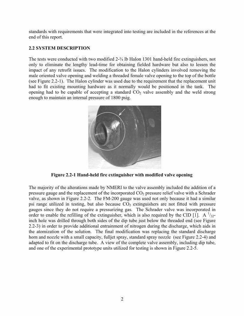
standards with requirements that were integrated into testing are included in the references at the end of this report. 2.2 SYSTEM DESCRIPTION The tests were conducted with two modified 2-¾ lb Halon 1301 hand-held fire extinguishers, not only to eliminate the lengthy lead-time for obtaining fielded hardware but also to lessen the impact of any retrofit issues. The modification to the Halon cylinders involved removing the male oriented valve opening and welding a threaded female valve opening to the top of the bottle (see Figure 2.2-1). The Halon cylinder was used due to the requirement that the replacement unit had to fit existing mounting hardware as it normally would be positioned in the tank. The opening had to be capable of accepting a standard CO2 valve assembly and the weld strong enough to maintain an internal pressure of 1800 psig.
The majority of the alterations made by NMERI to the valve assembly included the addition of a pressure gauge and the replacement of the incorporated CO2 pressure relief valve with a Schrader valve, as shown in Figure 2.2-2. The FM-200 gauge was used not only because it had a similar psi range utilized in testing, but also because CO2 extinguishers are not fitted with pressure gauges since they do not require a pressurizing gas. The Schrader valve was incorporated in order to enable the refilling of the extinguisher, which is also required by the CID [1]. A 1/32-inch hole was drilled through both sides of the dip tube just below the threaded end (see Figure 2.2-3) in order to provide additional entrainment of nitrogen during the discharge, which aids in the atomization of the solution. The final modification was replacing the standard discharge horn and nozzle with a small capacity, fulljet spray, standard spray nozzle (see Figure 2.2-4) and adapted to fit on the discharge tube. A view of the complete valve assembly, including dip tube, and one of the experimental prototype units utilized for testing is shown in Figure 2.2-5.
Figure 2.2-1 Hand-held fire extinguisher with modified valve opening
3
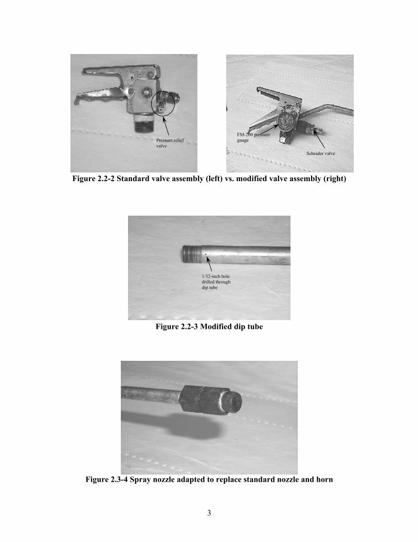
Figure 2.2-2 Standard valve assembly (left) vs. modified valve assembly (right)
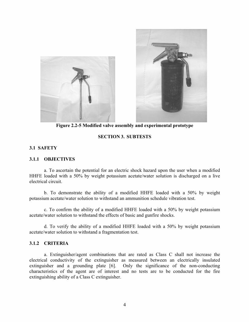
Figure 2.2-3 Modified dip tube
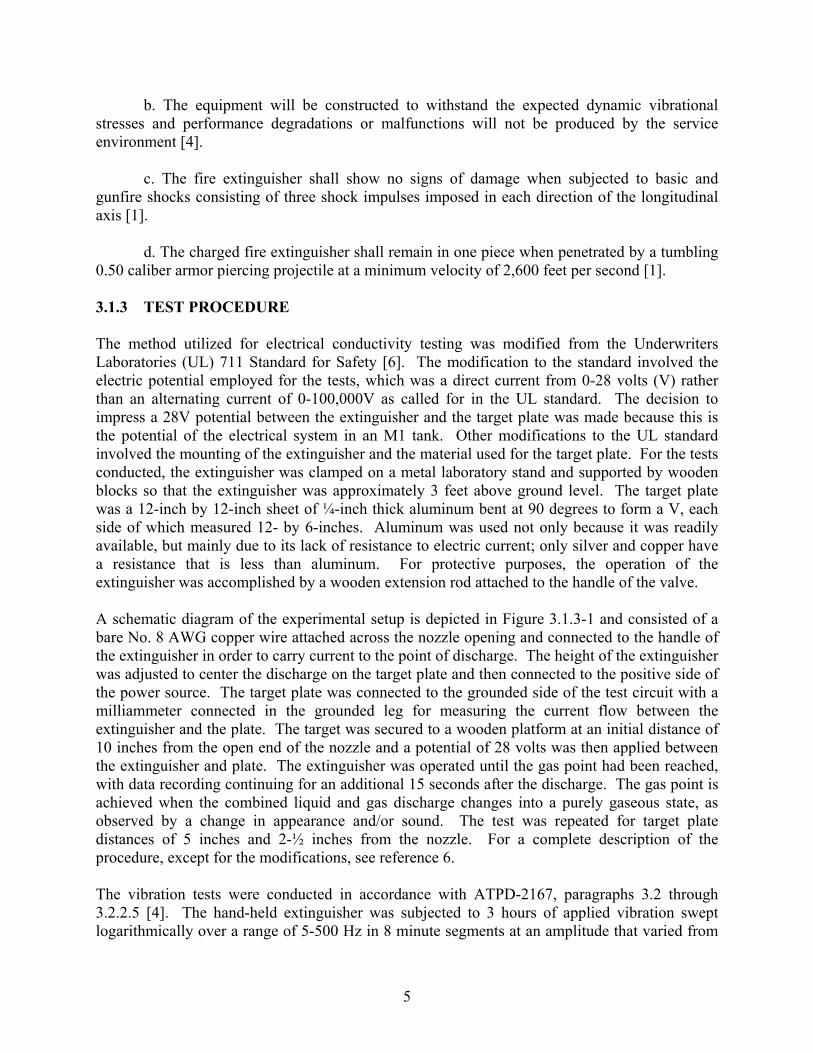
Figure 2.3-4 Spray nozzle adapted to replace standard nozzle and horn
1/32-inch hole drilled through dip tube
FM-200 pressure gauge
Schrader valve
Pressure relief valve
4
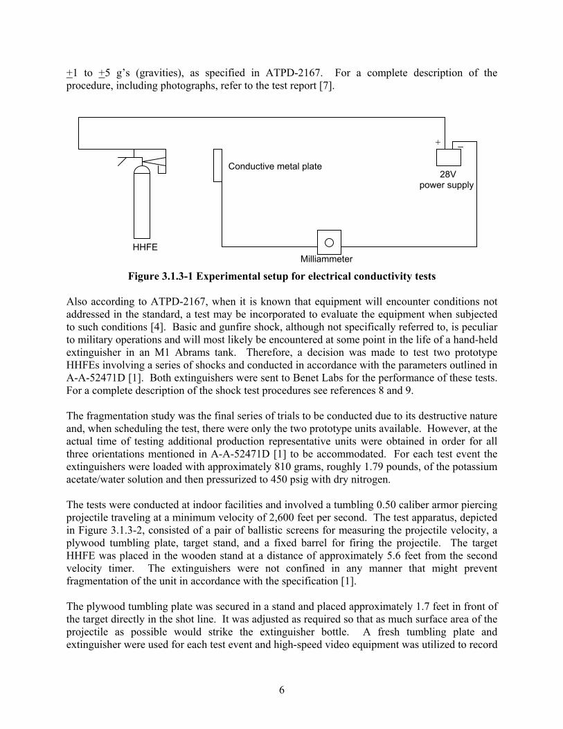
Figure 2.2-5 Modified valve assembly and experimental prototype
SECTION 3. SUBTESTS
3.1 SAFETY 3.1.1 OBJECTIVES
a. To ascertain the potential for an electric shock hazard upon the user when a modified HHFE loaded with a 50% by weight potassium acetate/water solution is discharged on a live electrical circuit.
b. To demonstrate the ability of a modified HHFE loaded with a 50% by weight
potassium acetate/water solution to withstand an ammunition schedule vibration test. c. To confirm the ability of a modified HHFE loaded with a 50% by weight potassium
acetate/water solution to withstand the effects of basic and gunfire shocks. d. To verify the ability of a modified HHFE loaded with a 50% by weight potassium
acetate/water solution to withstand a fragmentation test. 3.1.2 CRITERIA
a. Extinguisher/agent combinations that are rated as Class C shall not increase the electrical conductivity of the extinguisher as measured between an electrically insulated extinguisher and a grounding plate [6]. Only the significance of the non-conducting characteristics of the agent are of interest and no tests are to be conducted for the fire extinguishing ability of a Class C extinguisher.
5
b. The equipment will be constructed to withstand the expected dynamic vibrational stresses and performance degradations or malfunctions will not be produced by the service environment [4].
c. The fire extinguisher shall show no signs of damage when subjected to basic and
gunfire shocks consisting of three shock impulses imposed in each direction of the longitudinal axis [1].
d. The charged fire extinguisher shall remain in one piece when penetrated by a tumbling
0.50 caliber armor piercing projectile at a minimum velocity of 2,600 feet per second [1]. 3.1.3 TEST PROCEDURE The method utilized for electrical conductivity testing was modified from the Underwriters Laboratories (UL) 711 Standard for Safety [6]. The modification to the standard involved the electric potential employed for the tests, which was a direct current from 0-28 volts (V) rather than an alternating current of 0-100,000V as called for in the UL standard. The decision to impress a 28V potential between the extinguisher and the target plate was made because this is the potential of the electrical system in an M1 tank. Other modifications to the UL standard involved the mounting of the extinguisher and the material used for the target plate. For the tests conducted, the extinguisher was clamped on a metal laboratory stand and supported by wooden blocks so that the extinguisher was approximately 3 feet above ground level. The target plate was a 12-inch by 12-inch sheet of ¼-inch thick aluminum bent at 90 degrees to form a V, each side of which measured 12- by 6-inches. Aluminum was used not only because it was readily available, but mainly due to its lack of resistance to electric current; only silver and copper have a resistance that is less than aluminum. For protective purposes, the operation of the extinguisher was accomplished by a wooden extension rod attached to the handle of the valve. A schematic diagram of the experimental setup is depicted in Figure 3.1.3-1 and consisted of a bare No. 8 AWG copper wire attached across the nozzle opening and connected to the handle of the extinguisher in order to carry current to the point of discharge. The height of the extinguisher was adjusted to center the discharge on the target plate and then connected to the positive side of the power source. The target plate was connected to the grounded side of the test circuit with a milliammeter connected in the grounded leg for measuring the current flow between the extinguisher and the plate. The target was secured to a wooden platform at an initial distance of 10 inches from the open end of the nozzle and a potential of 28 volts was then applied between the extinguisher and plate. The extinguisher was operated until the gas point had been reached, with data recording continuing for an additional 15 seconds after the discharge. The gas point is achieved when the combined liquid and gas discharge changes into a purely gaseous state, as observed by a change in appearance and/or sound. The test was repeated for target plate distances of 5 inches and 2-½ inches from the nozzle. For a complete description of the procedure, except for the modifications, see reference 6. The vibration tests were conducted in accordance with ATPD-2167, paragraphs 3.2 through 3.2.2.5 [4]. The hand-held extinguisher was subjected to 3 hours of applied vibration swept logarithmically over a range of 5-500 Hz in 8 minute segments at an amplitude that varied from
6
+1 to +5 g’s (gravities), as specified in ATPD-2167. For a complete description of the procedure, including photographs, refer to the test report [7].
Figure 3.1.3-1 Experimental setup for electrical conductivity tests
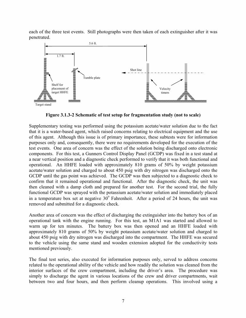
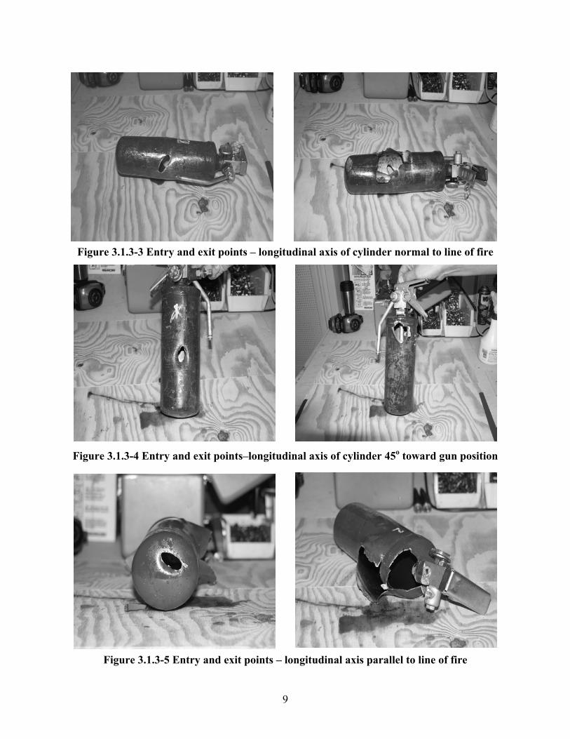
Also according to ATPD-2167, when it is known that equipment will encounter conditions not addressed in the standard, a test may be incorporated to evaluate the equipment when subjected to such conditions [4]. Basic and gunfire shock, although not specifically referred to, is peculiar to military operations and will most likely be encountered at some point in the life of a hand-held extinguisher in an M1 Abrams tank. Therefore, a decision was made to test two prototype HHFEs involving a series of shocks and conducted in accordance with the parameters outlined in A-A-52471D [1]. Both extinguishers were sent to Benet Labs for the performance of these tests. For a complete description of the shock test procedures see references 8 and 9. The fragmentation study was the final series of trials to be conducted due to its destructive nature and, when scheduling the test, there were only the two prototype units available. However, at the actual time of testing additional production representative units were obtained in order for all three orientations mentioned in A-A-52471D [1] to be accommodated. For each test event the extinguishers were loaded with approximately 810 grams, roughly 1.79 pounds, of the potassium acetate/water solution and then pressurized to 450 psig with dry nitrogen. The tests were conducted at indoor facilities and involved a tumbling 0.50 caliber armor piercing projectile traveling at a minimum velocity of 2,600 feet per second. The test apparatus, depicted in Figure 3.1.3-2, consisted of a pair of ballistic screens for measuring the projectile velocity, a plywood tumbling plate, target stand, and a fixed barrel for firing the projectile. The target HHFE was placed in the wooden stand at a distance of approximately 5.6 feet from the second velocity timer. The extinguishers were not confined in any manner that might prevent fragmentation of the unit in accordance with the specification [1]. The plywood tumbling plate was secured in a stand and placed approximately 1.7 feet in front of the target directly in the shot line. It was adjusted as required so that as much surface area of the projectile as possible would strike the extinguisher bottle. A fresh tumbling plate and extinguisher were used for each test event and high-speed video equipment was utilized to record
Milliammeter
+
HHFE
Conductive metal plate 28V power supply
_
7
each of the three test events. Still photographs were then taken of each extinguisher after it was penetrated.
Figure 3.1.3-2 Schematic of test setup for fragmentation study (not to scale) Supplementary testing was performed using the potassium acetate/water solution due to the fact that it is a water-based agent, which raised concerns relating to electrical equipment and the use of this agent. Although this issue is of primary importance, these subtests were for information purposes only and, consequently, there were no requirements developed for the execution of the test events. One area of concern was the effect of the solution being discharged onto electronic components. For this test, a Gunners Control Display Panel (GCDP) was fixed in a test stand at a near vertical position and a diagnostic check performed to verify that it was both functional and operational. An HHFE loaded with approximately 810 grams of 50% by weight potassium acetate/water solution and charged to about 450 psig with dry nitrogen was discharged onto the GCDP until the gas point was achieved. The GCDP was then subjected to a diagnostic check to confirm that it remained operational and functional. After the diagnostic check, the unit was then cleaned with a damp cloth and prepared for another test. For the second trial, the fully functional GCDP was sprayed with the potassium acetate/water solution and immediately placed in a temperature box set at negative 30o Fahrenheit. After a period of 24 hours, the unit was removed and submitted for a diagnostic check. Another area of concern was the effect of discharging the extinguisher into the battery box of an operational tank with the engine running. For this test, an M1A1 was started and allowed to warm up for ten minutes. The battery box was then opened and an HHFE loaded with approximately 810 grams of 50% by weight potassium acetate/water solution and charged to about 450 psig with dry nitrogen was discharged into the compartment. The HHFE was secured to the vehicle using the same stand and wooden extension adopted for the conductivity tests mentioned previously. The final test series, also executed for information purposes only, served to address concerns related to the operational ability of the vehicle and how readily the solution was cleaned from the interior surfaces of the crew compartment, including the driver’s area. The procedure was simply to discharge the agent in various locations of the crew and driver compartments, wait between two and four hours, and then perform cleanup operations. This involved using a
Target stand
Shelf for placement of target HHFE
1.7 ft.
Velocity timers
Shot line
Tumble plate
5.6 ft.
8
cleaning solution (Spray Nine), a rag or brush (for hard to reach places), and a hose for rinsing water, with 30 psig of supplied water pressure. Two extinguishers were required to completely saturate all of the stations in an M1A1 combat vehicle. The locations that were sprayed in the gunner’s area not only included the entire floor and gun tube undercarriage, but also behind the foot rest and plate along the left side of the seat and through the expanded metal turret basket along the right side of the seat. The areas covered with solution in the commander’s and loader’s stations were the floor, gun breach, and through the turret basket around both seats. As for the driver’s station, the areas behind and under the seat were thoroughly saturated as well as the foot pedals and other controls. 3.1.4 TEST FINDINGS The voltage test series was conducted without incident. There were 3 trials performed with the distance between the nozzle tip and energized aluminum target plate being 10, 5, and 2 ½ inches respectively. The target was supplied with an electric potential of 28V and the extinguisher was connected to the grounded leg of the circuit. There was no detection of electric current back to the extinguisher when the potassium acetate/water mist was discharged onto the energized plate at any of the 3 distances. The vibration tests were completed without incident, in accordance with ATPD-2167 [4]. There was no apparent physical damage to the fire extinguishers and there were no performance degradations or malfunctions as a result of this test. The vibration test profiles are presented in reference 7 at the end of this report. As mentioned previously, Benet Labs performed the basic and gunfire shock test series using two production representative hand-held extinguishers. The results indicated that the two units subjected to the shocks suffered no apparent internal or external physical damage and there were no degradations or malfunctions regarding the performance of the extinguishers. For a complete description of the test results refer to references 8 and 9 at the end of this report. The fragmentation test series was also completed without incident and the extinguishers remained intact when penetrated by a tumbling 0.50 caliber armor piercing projectile, as observed in Figures 3.1.4-1 through 3.1.4-3. For each test event, the entry point of the projectile was below the liquid level in order to determine if hydraulic ram affected the fragmentation or shattering of the units. Although this was not the main purpose of this portion of testing, hydraulic ram did not impact the extinguishers in any fashion other than to aid in evacuating the cylinder of agent. The projectile velocities for the 3 test events were 2,649 feet per second (ft/s), 2,661 ft/s, and 2,665 ft/s respectively. The GCDP remained functional and operational after being saturated with the potassium acetate/water solution. All of the diagnostic checks were completed without errors. However, after spraying the unit and conditioning it at -30o F for 24 hours, it failed the same diagnostic analysis. Following discussion with a manufacturer’s representative, it was determined that -30 degrees was the lower limit that the unit could withstand because it was fully functional after allowing a period of 72 hours to elapse.
9
Figure 3.1.3-3 Entry and exit points – longitudinal axis of cylinder normal to line of fire
Figure 3.1.3-4 Entry and exit points–longitudinal axis of cylinder 45o toward gun position
Figure 3.1.3-5 Entry and exit points – longitudinal axis parallel to line of fire
10
As for the discharge into the battery box, there were no issues or concerns raised as a result of the test. Since there are drain openings in this compartment, the solution quickly evacuated the battery box and the small remaining pools presented no short circuit hazard to the equipment. There were also no issues raised after the discharge of potassium acetate/water solution in the crew and driver compartments of an operational M1A1. A period of twenty-six hours was allowed to elapse before the cleaning process began and the solution was readily cleaned from all surfaces using a hose, supplied with 30 psig of water pressure, and wiping with a rag or brush as needed. No residue remained on any of the cleaned surfaces even after waiting an additional twenty four hours from the completion of cleanup operations. Approximately one week later, the same M1A1 was moved from the test site where the discharges and cleaning took place and, according to the driver, no operational deficiencies were experienced. 3.1.5 CONCLUSIONS
a. The results indicated that the M1A1 hand-held fire extinguisher loaded with 50% by weight potassium acetate/water solution will not present a shock hazard to the user when the agent is discharged on a target plate with a supplied electric potential of up to 28 volts at target distances of 10, 5, and 2 ½ inches.
b. The M1A1 hand-held fire extinguisher filled with a 50% by weight potassium
acetate/water solution did not suffer any damage that degraded its performance or caused it to malfunction upon completion of the installed equipment vibration tests [7].
c. The M1A1 hand-held fire extinguisher filled with a 50% by weight potassium
acetate/water solution and charged with dry nitrogen to 450 psig did not suffer any damage that degraded its performance or caused it to malfunction upon completion of the basic and gunfire shock tests [8, 9].
d. The M1A1 hand-held fire extinguishers filled with a 50% by weight potassium acetate/water solution remained intact in all of the test orientations after being penetrated by a tumbling 0.50 caliber armor piercing projectile travelling at least 2,600 feet per second. 3.2 OPERATION 3.2.1 OBJECTIVE To determine the operability of a modified HHFE containing a 50% by weight potassium acetate/water solution under normal operating conditions and at temperature extremes. 3.2.2 CRITERIA
a. Not less than 90% by weight of agent shall be discharged when a hand-held portable extinguisher is operated at an angle of 45o in any direction from the intended operating position and conditioned to 70o F for a minimum of 16 hours [3].
11
b. The duration of effective discharge of an extinguisher shall not be less than 8 seconds, or the minimum duration specified in UL 711, for the appropriate Class A or Class B rating, whichever is longer [3].
c. Not less than 90% by weight of the filled capacity of agent shall be discharged when an
extinguisher is operated after being conditioned at -50o F for at least 16 hours. There shall be no leakage from the extinguisher during the conditioning cycle [3]. The low temperature reference for this test was incorporated from Commercial Item Description A-A-52471D [1].
d. Not less than 90% by weight of the filled capacity of agent shall be discharged when an extinguisher is operated after being conditioned at +120o F for at least 16 hours. There shall be no leakage from the extinguisher during the conditioning cycle [3].
e. The fire extinguisher shall be capable of safe storage at temperatures from -60o F for a period of 72 hours to +145o F for a period of 4 hours daily [1]. There shall be no leakage from the extinguisher during the conditioning cycle. 3.2.3 TEST PROCEDURE This portion of testing was conducted in accordance with UL 1093 [3] and completed concurrently with the efficacy test series (section 3.3) so that multiple requirements could be fulfilled with a single test event. The procedure was performed utilizing approximately 810.0 grams of 50% by weight potassium acetate/water solution at a charging pressure of 450 psig. Time coded videotape was employed for an accurate determination of the duration of discharge and fire out time to within + 0.1 seconds.
a. Operation Test – Weigh the charged extinguisher(s) and record the value. Condition the unit(s) at 70o F for a minimum of 16 hours prior to testing and reweigh to determine if there has been any leakage. Operate the extinguisher at an angle of 45o from the vertical position and discharge the agent until the gas point has been reached. This is the point at which the combined liquid and gas discharge changes into a purely gaseous state, as observed by a change in appearance and/or sound. Also make note of any concerns regarding the operation of the extinguisher. Reweigh the unit(s) and record the amount of agent that has been expelled. Calculate the percentage of the filled capacity that was discharged.
b. Discharge Duration Test – Weigh the charged extinguisher(s) and record the value.
Condition the unit(s) at 70o F for a minimum of 16 hours prior to testing and reweigh to determine if there has been any leakage. Discharge the extinguisher(s) and record the time to gas point. This test was also performed at the temperature extremes mentioned below to determine the effects on the duration of discharge and/or spray pattern.
c. Weigh the charged extinguisher(s) and record the value. Condition the unit(s) at -25o F for a minimum of 16 hours prior to testing and reweigh to determine if there has been any leakage. The low temperature extreme was adjusted from -50 to -25o F based on the assumption that -25o F is the lowest temperature the HHFE would experience while still having to retain its
12
effectiveness at extinguishing a pool fire. Discharge the extinguisher(s) and record the time to gas point, along with any unusual operating characteristics. Reweigh the unit(s) and record the amount of agent that has been expelled. Calculate the percentage of the filled capacity that was discharged.
d. Weigh the charged extinguisher(s) and record the value. Condition the unit(s) at +120o
F for a minimum of 16 hours prior to testing and reweigh to determine if there has been any leakage. Discharge the extinguisher(s) and record the time to gas point, along with any unusual operating characteristics. Reweigh the unit(s) and record the amount of agent that has been expelled. Calculate the percentage of the filled capacity that was discharged.
e. Weigh the charged extinguisher(s) and record the value. Condition the unit(s) at -60o F
for 72 hours to +145o F for 4 hours [1] and reweigh to determine if there has been any leakage during storage. Discharge the extinguisher(s) and report any unusual operating characteristics. 3.2.4 TEST FINDINGS The trials were conducted with the two HHFEs modified by NMERI, as described in Section 2.2. Additionally, the operation testing of the experimental prototype HHFEs was incorporated with the efficacy test trials and the results are presented in Table 3.3.4-1 through 3.3.4-3. A few trials were performed at -60o F to determine the operational ability of the HHFE. However, the focus was not on the performance of the unit at quenching a pan fire but on the functioning of the valve assembly and the extinguisher in general.
a. For the trials performed with the extinguishers conditioned to approximately 70o F,
there were no deficiencies regarding the operation of the units and no leakage of agent occurred during any of the conditioning periods for all ten trials. The average discharge capacity was 95.3% + 2.7%, according to the test results presented in Table 3.3.4-2.
b. The average duration of discharge at 70o F was 19.8 seconds + 4.8 seconds according
to the test results presented in Table 3.3.4-2. No leakage of agent occurred during any of the conditioning periods for all ten trials. As reported in Table 3.3.4-1, the average duration of discharge at 120o F was 16.9 seconds + 4.9 seconds and no leakage of agent occurred during any of the conditioning periods for all ten trials. As depicted in Table 3.3.4-3, the average duration of discharge at -25o F was 14.5 seconds + 3.5 seconds and no leakage of agent occurred during any of the conditioning periods for all ten trials.
c. The average duration of discharge at -25o F was 14.5 seconds + 3.5 seconds and the average discharge capacity was 95.6% + 2.6%, as reported in Table 3.3.4-3. No leakage of agent occurred during any of the conditioning periods for all ten trials and there were no operational deficiencies observed.
d. There were no deficiencies regarding the operation of the units when temperature
conditioned to approximately 120o F and neither of the extinguishers leaked during any of the temperature conditioning periods for all ten trials conducted. As reported in Table 3.3.4-1, the
13
average duration of discharge at this temperature was 16.9 seconds + 4.9 seconds and the average discharge capacity was 96.7% + 1.1%.
e. There were no deficiencies regarding the operation of the units and no leakage of agent
occurred during the conditioning period at -60o F for 72 hours to +145o F for 4 hours. 3.2.5 CONCLUSIONS
a. After conditioning the experimental prototype HHFEs at 70o F for a period of 24 hours, the average discharge capacity was 95.3% + 2.7% and there was no leakage of agent during the conditioning period.
b. The average duration of effective discharge of the experimental prototype HHFEs was
16.9 seconds + 4.9 seconds at 120o F, 19.8 seconds + 4.8 seconds at 70o F, and 14.5 seconds + 3.5 seconds at -25o F. For each temperature, the extinguishers were conditioned for a minimum of 24 hours.
c. After conditioning the experimental prototype HHFEs at -25o F for a period of 24
hours, the average discharge capacity was 95.6% + 2.6% and there was no leakage of agent during the conditioning period.
d. After conditioning the experimental prototype HHFEs at 120o F for a period of 24
hours, the average discharge capacity was 96.7% + 1.1% and there was no leakage of agent during the conditioning period.
e. The experimental prototype HHFEs were capable of safe storage at temperatures from
-60o F for a period of 72 hours to +145o F for a period of 4 hours daily and there was no leakage of agent during the conditioning cycle. 3.3 EFFICACY 3.3.1 OBJECTIVE To determine the Class B effectiveness of hand-held fire extinguishers charged with alternative agents as potential replacements for the Halon 1301 units currently in service. 3.3.2 CRITERION The fire extinguisher shall have the fire extinguishing potential of at least a 2-B fire in accordance with UL 711 [6]. 3.3.3 TEST PROCEDURE Operator skill and technique are an important and unavoidable factor in the performance of HHFEs. It was also recognized that a firefighter’s knowledge and experience regarding the attack on a fire is an advantage, which is pertinent when determining the performance of an
14
extinguisher during fire testing. Therefore, APG firefighters’ were utilized not only to maximize the performance of the extinguishers, but also to give a better indication of the performance of the extinguisher when used by a trained individual. This portion of testing was conducted in accordance with UL 711 [6] and completed concurrently with the operation test series (section 3.2) so that multiple requirements could be fulfilled with a single test event. The procedure was performed utilizing approximately 810.0 grams of 50% by weight potassium acetate/water solution at a charging pressure of 450 psig. Time coded videotape was employed for an accurate determination of the duration of discharge and fire out time to within + 0.1 seconds. Three test series were conducted with the extinguishers conditioned at +120, +70, and -25 degrees Fahrenheit. After being conditioned for 24 hours at the desired temperature, the loaded extinguishers were immediately discharged on a 2-B pan fire containing JP-8 fuel. An additional series of tests was conducted in order to determine the effectiveness of the potassium acetate/water solution against a combination Class A/B fire. These trials were performed for information only and, therefore, no requirements were developed for the execution of this objective. For each trial of this series, a V-pack filter was soaked with roughly four liters of JP-8 fuel. After waiting approximately two minutes for the fuel to soak in, the filter material was ignited and allowed to burn for approximately one minute. At this time, an APG firefighter attempted to extinguish the fire using an HHFE loaded with approximately 810 grams of 50% by weight potassium acetate/water solution and pressurized to 450 psig with dry nitrogen. 3.3.4 TEST FINDINGS The first phase of testing was to determine the efficacy of the potassium acetate agent against 2-B pan fires using JP-8 fuel. Three test series were conducted with the extinguishers conditioned at +120, +70, and -25 degrees Fahrenheit. For each trial, the extinguisher was filled with approximately 810 grams of potassium acetate solution and pressurized to 450 psig with dry nitrogen. The loaded extinguishers were then conditioned for 24 hours at the desired temperature. After the conditioning period, the extinguishers were immediately discharged on a pan fire containing approximately 3 gallons of JP-8 fuel. In addition to efficacy testing, each trial was also evaluated concurrently in terms of discharge capacity and duration. The opening test series used extinguishers conditioned at 120o F and the results are shown in Table 3.3.4-1. The first two trials were attempted on a 5-B pan fire without any success. Due to this ineffectiveness, the switch to a 2-B pan was made and used for the remaining trials at all temperatures. For the ten trials that utilized the 2-B pan, there was a 60% success rate. However, at the end of the test series it was observed that one of the extinguishers had a spray nozzle that was clogged with debris, which undoubtedly had an adverse affect on the fire extinguishing potential as well as the characteristics of the discharge. As a result, a search was initiated for a potassium acetate/water solution that contained corrosion inhibitors. The minor increase/decrease in pre-discharge weights versus pre-conditioned weights was attributed to dirt accumulation during the handling of the extinguishers and/or placement of FE on the scale (i.e. slight weight variation when FE placed on different spots of scale).
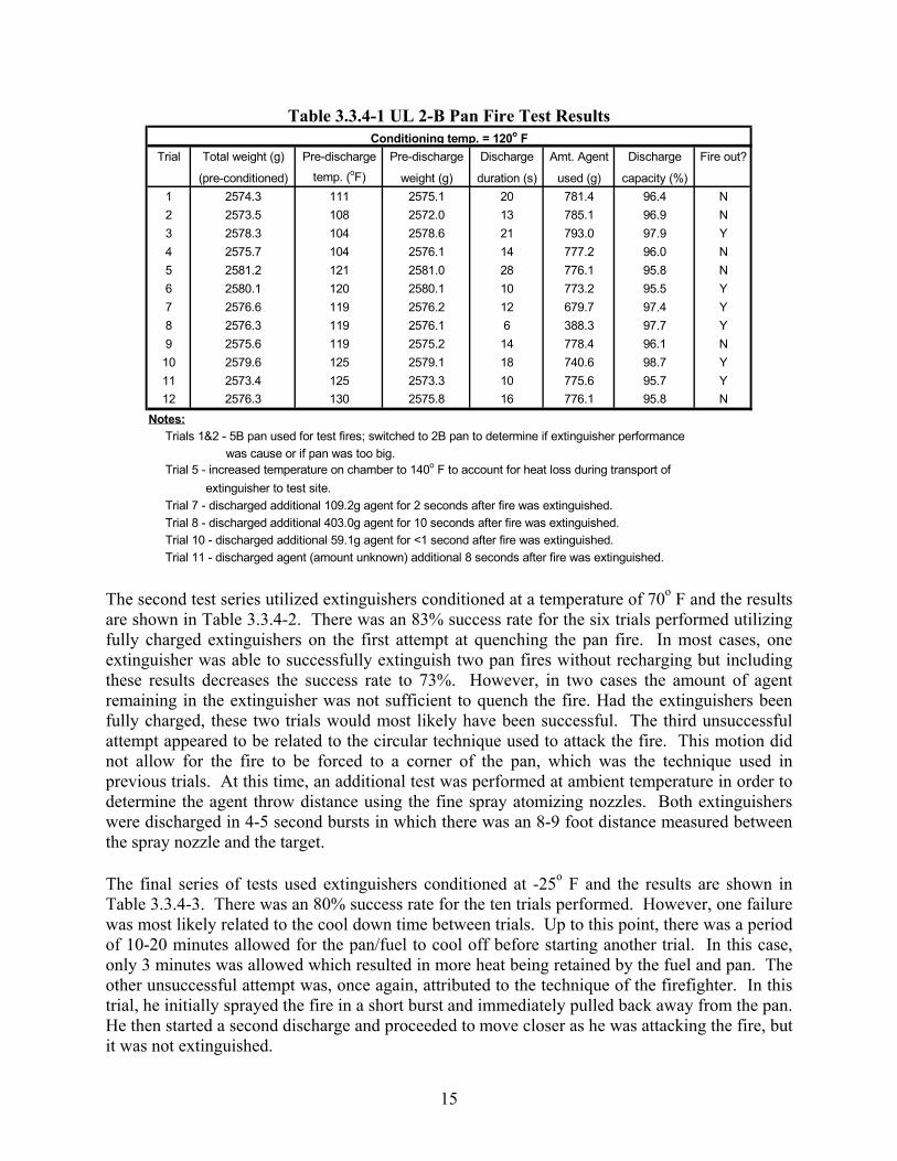
15
Table 3.3.4-1 UL 2-B Pan Fire Test Results
Trial Total weight (g) Pre-discharge Pre-discharge Discharge Amt. Agent Discharge Fire out?
(pre-conditioned) temp. (oF) weight (g) duration (s) used (g) capacity (%)1 2574.3 111 2575.1 20 781.4 96.4 N2 2573.5 108 2572.0 13 785.1 96.9 N3 2578.3 104 2578.6 21 793.0 97.9 Y4 2575.7 104 2576.1 14 777.2 96.0 N5 2581.2 121 2581.0 28 776.1 95.8 N6 2580.1 120 2580.1 10 773.2 95.5 Y7 2576.6 119 2576.2 12 679.7 97.4 Y8 2576.3 119 2576.1 6 388.3 97.7 Y9 2575.6 119 2575.2 14 778.4 96.1 N10 2579.6 125 2579.1 18 740.6 98.7 Y11 2573.4 125 2573.3 10 775.6 95.7 Y12 2576.3 130 2575.8 16 776.1 95.8 N
Notes: Trials 1&2 - 5B pan used for test fires; switched to 2B pan to determine if extinguisher performance was cause or if pan was too big. Trial 5 - increased temperature on chamber to 140o F to account for heat loss during transport of extinguisher to test site. Trial 7 - discharged additional 109.2g agent for 2 seconds after fire was extinguished. Trial 8 - discharged additional 403.0g agent for 10 seconds after fire was extinguished. Trial 10 - discharged additional 59.1g agent for <1 second after fire was extinguished. Trial 11 - discharged agent (amount unknown) additional 8 seconds after fire was extinguished.
Conditioning temp. = 120o F
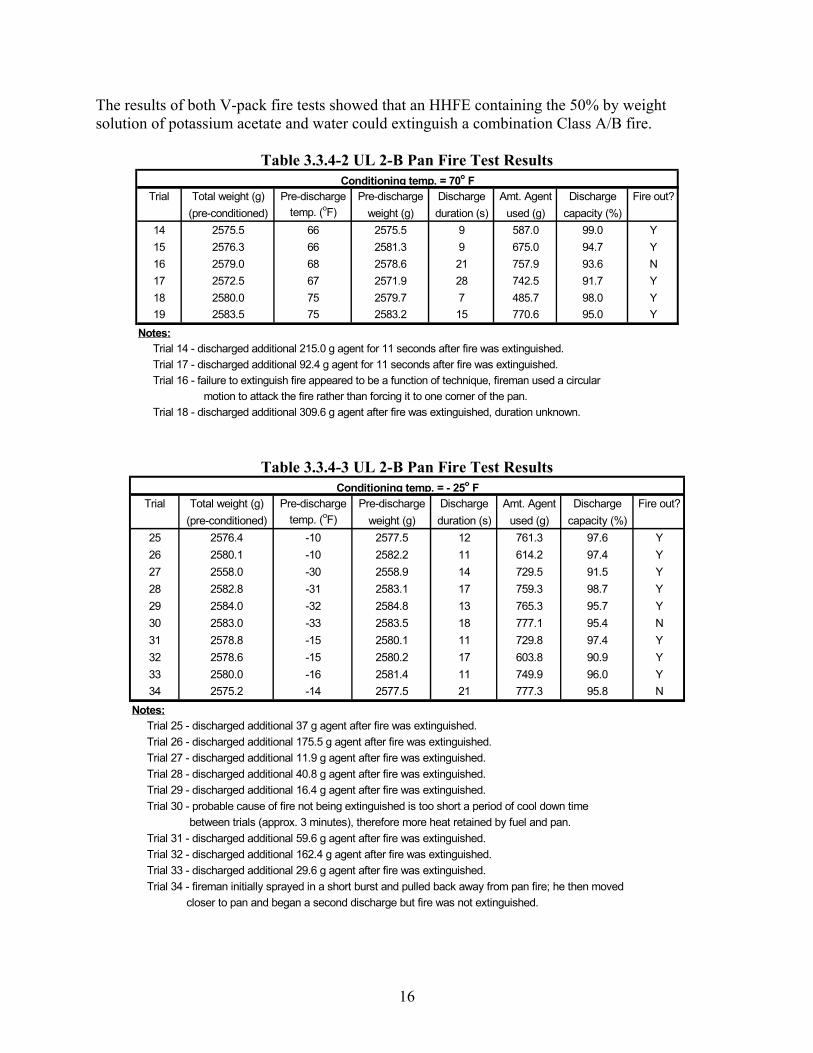
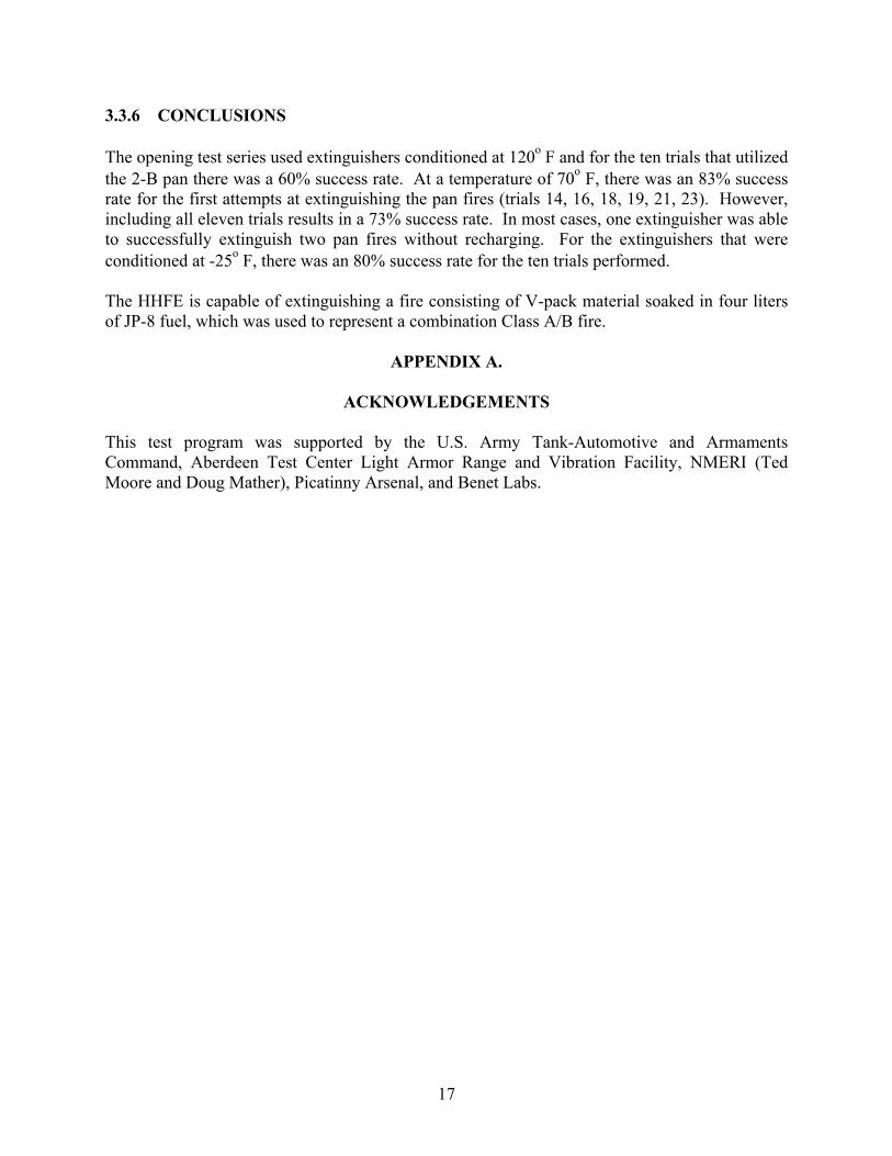
The second test series utilized extinguishers conditioned at a temperature of 70o F and the results are shown in Table 3.3.4-2. There was an 83% success rate for the six trials performed utilizing fully charged extinguishers on the first attempt at quenching the pan fire. In most cases, one extinguisher was able to successfully extinguish two pan fires without recharging but including these results decreases the success rate to 73%. However, in two cases the amount of agent remaining in the extinguisher was not sufficient to quench the fire. Had the extinguishers been fully charged, these two trials would most likely have been successful. The third unsuccessful attempt appeared to be related to the circular technique used to attack the fire. This motion did not allow for the fire to be forced to a corner of the pan, which was the technique used in previous trials. At this time, an additional test was performed at ambient temperature in order to determine the agent throw distance using the fine spray atomizing nozzles. Both extinguishers were discharged in 4-5 second bursts in which there was an 8-9 foot distance measured between the spray nozzle and the target. The final series of tests used extinguishers conditioned at -25o F and the results are shown in Table 3.3.4-3. There was an 80% success rate for the ten trials performed. However, one failure was most likely related to the cool down time between trials. Up to this point, there was a period of 10-20 minutes allowed for the pan/fuel to cool off before starting another trial. In this case, only 3 minutes was allowed which resulted in more heat being retained by the fuel and pan. The other unsuccessful attempt was, once again, attributed to the technique of the firefighter. In this trial, he initially sprayed the fire in a short burst and immediately pulled back away from the pan. He then started a second discharge and proceeded to move closer as he was attacking the fire, but it was not extinguished.
16
The results of both V-pack fire tests showed that an HHFE containing the 50% by weight solution of potassium acetate and water could extinguish a combination Class A/B fire.
Table 3.3.4-2 UL 2-B Pan Fire Test Results
Trial Total weight (g) Pre-discharge Pre-discharge Discharge Amt. Agent Discharge Fire out?(pre-conditioned) temp. (oF) weight (g) duration (s) used (g) capacity (%)
14 2575.5 66 2575.5 9 587.0 99.0 Y15 2576.3 66 2581.3 9 675.0 94.7 Y16 2579.0 68 2578.6 21 757.9 93.6 N17 2572.5 67 2571.9 28 742.5 91.7 Y18 2580.0 75 2579.7 7 485.7 98.0 Y19 2583.5 75 2583.2 15 770.6 95.0 Y
Notes: Trial 14 - discharged additional 215.0 g agent for 11 seconds after fire was extinguished. Trial 17 - discharged additional 92.4 g agent for 11 seconds after fire was extinguished. Trial 16 - failure to extinguish fire appeared to be a function of technique, fireman used a circular motion to attack the fire rather than forcing it to one corner of the pan. Trial 18 - discharged additional 309.6 g agent after fire was extinguished, duration unknown.
Conditioning temp. = 70o F
Table 3.3.4-3 UL 2-B Pan Fire Test Results
Trial Total weight (g) Pre-discharge Pre-discharge Discharge Amt. Agent Discharge Fire out?(pre-conditioned) temp. (oF) weight (g) duration (s) used (g) capacity (%)
25 2576.4 -10 2577.5 12 761.3 97.6 Y26 2580.1 -10 2582.2 11 614.2 97.4 Y27 2558.0 -30 2558.9 14 729.5 91.5 Y28 2582.8 -31 2583.1 17 759.3 98.7 Y29 2584.0 -32 2584.8 13 765.3 95.7 Y30 2583.0 -33 2583.5 18 777.1 95.4 N31 2578.8 -15 2580.1 11 729.8 97.4 Y32 2578.6 -15 2580.2 17 603.8 90.9 Y33 2580.0 -16 2581.4 11 749.9 96.0 Y34 2575.2 -14 2577.5 21 777.3 95.8 N
Notes: Trial 25 - discharged additional 37 g agent after fire was extinguished. Trial 26 - discharged additional 175.5 g agent after fire was extinguished. Trial 27 - discharged additional 11.9 g agent after fire was extinguished. Trial 28 - discharged additional 40.8 g agent after fire was extinguished. Trial 29 - discharged additional 16.4 g agent after fire was extinguished. Trial 30 - probable cause of fire not being extinguished is too short a period of cool down time between trials (approx. 3 minutes), therefore more heat retained by fuel and pan. Trial 31 - discharged additional 59.6 g agent after fire was extinguished. Trial 32 - discharged additional 162.4 g agent after fire was extinguished. Trial 33 - discharged additional 29.6 g agent after fire was extinguished. Trial 34 - fireman initially sprayed in a short burst and pulled back away from pan fire; he then moved closer to pan and began a second discharge but fire was not extinguished.
Conditioning temp. = - 25o F
17
3.3.6 CONCLUSIONS The opening test series used extinguishers conditioned at 120o F and for the ten trials that utilized the 2-B pan there was a 60% success rate. At a temperature of 70o F, there was an 83% success rate for the first attempts at extinguishing the pan fires (trials 14, 16, 18, 19, 21, 23). However, including all eleven trials results in a 73% success rate. In most cases, one extinguisher was able to successfully extinguish two pan fires without recharging. For the extinguishers that were conditioned at -25o F, there was an 80% success rate for the ten trials performed. The HHFE is capable of extinguishing a fire consisting of V-pack material soaked in four liters of JP-8 fuel, which was used to represent a combination Class A/B fire.
APPENDIX A.
ACKNOWLEDGEMENTS This test program was supported by the U.S. Army Tank-Automotive and Armaments Command, Aberdeen Test Center Light Armor Range and Vibration Facility, NMERI (Ted Moore and Doug Mather), Picatinny Arsenal, and Benet Labs.
18
APPENDIX B.
REFERENCES
1. A-A-52471D. “Commercial Item Description for Extinguisher, Fire, CO2, 2 ½-pound, with Bracket.” U.S. Army Tank-Automotive and Armaments Command. 22 March 1995. 2. Standard for Safety. “UL Standard 154 – Standard for Carbon-Dioxide Fire Extinguishers.” Underwriters Laboratories, Inc. Northbrook, IL. April 18, 1995. 3. Standard for Safety. “UL Standard 1093 – Halogenated Agent Fire Extinguishers.” Underwriters Laboratories, Inc. Northbrook, IL. November 28, 1990. 4. ATPD-2167. “M1 Tank Program, Environmental Test Methods for Land Mobility Vehicle Equipment.” General Dynamics Land Systems Division. 5 January 1990. 5. MIL-E-52031D. “Military Specification for Extinguishers, Fire, Vaporizing Liquid, CF3Br, 2-3/4 pound, with Bracket.” U.S. Army Mobility Equipment Research and Development Command. 05 September 1979. 6. Standard for Safety. “UL Standard 711 – Fire Extinguishers, Rating and Fire Testing of.” Underwriters Laboratories, Inc. Northbrook, IL. September 22, 1995. 7. Breen, Jim. “Laboratory Vibration Test of the M1A1 Hand Held Fire Extinguisher (Installed Equipment).” Report No. 02-AIT-043. Automotive Instrumentation Team. U. S. Army Aberdeen Test Center, MD. 4 June 2002. 8. Potkin, Alex. “Shock Testing of the Water Kacetate Fire Extinguisher 2.5 lb, with Bracket, Exterior Stowage Box.” Environmental Test Group. Picatinny Arsenal, NJ. September 2002. 9. Potkin, Alex. “Shock Testing of the Water Kacetate Fire Extinguisher 2.5 lb, with Bracket, Commander’s Ammo Stowage Box.” Environmental Test Group. Picatinny Arsenal, NJ. September 2002.
![1(i) M1A1A1A1 [4] M1A1 M1A1 [4] A1A1 A1 M1 B1 M1 ... packs/MS_MEI_NM.pdf6 -0.00218 sign change so root is correct to 3 dp [M1A1] [TOTAL 8] 3 h M T S 2 3.46410 2 3.65028 2 3.52616 2](https://img.pdfslide.us/doc/110x75/60e84fbad1b031344221d847/1i-m1a1a1a1-4-m1a1-m1a1-4-a1a1-a1-m1-b1-m1-packsmsmeinmpdf-6-000218.jpg)