Embed Size (px)
Citation preview
JME Journal of Mining & Environment, Vol.8, No.1, 2017, 111-130.
DOI: 10.22044/jme.2016.573
Evaluation of structural analysis of tunnel segmental lining using
beam-spring method and force-method (Case study: Chamshir water
conveyance tunnel)
M. Nikkhah
1*, S.S. Mousavi
1, Sh. Zare
1 and O. Khademhosseini
2
1. School of Mining, Petroleum & Geophysics Engineering, Shahrood University of Technology, Shahrood, Iran 2. School of Civil Engineering, Shahrood University of Technology, Shahrood, Iran
Received 20 November 2015; received in revised form 21 January 2016; accepted 25 January 2016
*Corresponding author: [email protected] (M. Nikkhah).
Abstract The joints between segmental rings can withstand a certain amount of bending moment as well as axial and
shear forces. Generally, in the structural analysis of tunnel segmental lining, the joints can be modeled as
elastic hinges or rotational springs, and their rigidity should be demonstrated in terms of the rigidity of the
joints or their rotational stiffness. Therefore, the bending moment acting on the tunnel lining is reduced.
Hence, the tunnel designers are free to choose a lining with a lower cost. In this research work, especially
considering the joints, the structural analysis of the segmental lining with variation in the flexural stiffness of
the joints ( ), soil resistance coefficient ( SK ), number of segmental lining joints, and joint arrangement of
segmental lining were carried out by the Force-Method equations. The imposed bending moment and axial
forces were computed based on the Beam-Spring method, which is widely used to analyze the internal forces
of segmental lining, and compared them with the results of the Force-Method equations. Then the effects of
joint arrangement patterns and joint rotational spring stiffness on the results of the Beam-Spring analysis
were evaluated. Finally, the optimum characteristics of the reinforced concrete segmental lining design were
evaluated using the interaction diagram of bending moments and axial forces. The results obtained showed
that the presented pattern for the segmental lining at the Chamshir tunnel was imposed against the external
pressures on the segmental lining with an acceptable safety factor.
Keywords: Tunnel, Design of Segmental Lining, Structural Analysis, Beam-Spring Method, Chamshir
Tunnel.
1. Introduction
With the development of shield-driven machines
and the advancement of construction technology,
the diameters of these tunnels may run the gamut
from about 5 m to more than 12 m. The
compatibility of shield-driven tunnels has been
improved by various intricate and difficult
geological conditions. In most shield-driven
tunnels, the connected jointed segmental precast
concrete linings are commonly used by the steel
bolts instead of the steel or cast iron segments.
Although the lining of a shield-driven tunnel is
not a continuous ring structure due to the
existence of joints, the effect of joints on the
internal forces and displacements should be
considered in the lining design. Generally, the
influence of joints on the bending moment and
axial forces is one of the main elements in the
segmental lining design of shield-driven tunnels.
It happens due to the difference between the joint
and segment rigidity in the continuous form
structure. Recent research works have indicated
that the segment joint has a maximum deflection
compared to the main body. Thus the designers
have assumed the hinges of segments as a critical
part of segment in the design. The cover of
tunnels usually has been considered by a
Nikkhah et al./ Journal of Mining & Environment, Vol.8, No.1, 2017
112
dimensionless parameter called the flexural
stiffness coefficient, which was presented and
completed by Peck and Einstein in 1972 and
1979. The flextural stiffness coefficient indicates
the relationship between the host rock and the
structural features of the support system. Flextural
stiffness plays an important role in the stability of
tunnel lining. In fact, the internal bending moment
would be decreased by increasing the flextural
stiffness. This coefficient is defined by the
following equation [1, 2]:
2
1
6
1
S
S
E
FEI
(1)
where SE , S , E , I , and are the Young's
modulus of rock mass, Poisson's ratio of rock,
Young's modulus of lining, moment inertia of
lining, and Poisson’s ratio of lining, respectively.
In 1975, Wood proposed that the effective
moment inertia of the segmental lining should be
revised according to the following equation [3]:
2
)4
( O jI I IN
(2)
where OI and jI represent the moment inertia of
lining without joints (continuous lining) and
moment inertia of lining in joint position,
respectively.
Wood has also found that the presence of joints
does not affect the rigidity of lining for four or
fewer lining segments. The earth pressure acting
around a tunnel has been assumed to be an
elliptical shape in this model. To obtain the
elliptical shape of the initial loading, we need a
sufficient overburden thickness [3]. Therefore,
Wood's model is more applicable to deep tunnels
since the assumption may not be valid for shallow
tunnels. In 1996, Bickel et al. have proposed a 2D
model to simulate the segment joints using lower
stiffness parameters [4]. This model assumes that
the stiffness (effective modulus of the elasticity)
of a segmental ring is half of a monolithic ring by
the inertia moment of the practical coffered
precast segments ranging from 60-80% of those
solid sections with the same thickness. In the
wake of the reduced stiffness, this model is more
flexible than the continuous lining, and is
expected to yield less values for the bending
moment and hoop forces. Furthermore, Koyama
and Nishimura (1998) have developed a model
similar to the former model by Bickel et al. [5].
According to this model, the tunnel lining is
assumed to be a continuous ring with a discounted
rigidity by applying a reduction factor η value to
the bending rigidity ( EI ) of lining. Koyama and
Nishimura (1998) found η after a full-ring
structural testing. In the absence of the
experimental data, the value for could be
assumed to be in the range of 0.6-1.0 for the
preliminary design analysis [5]. For instance, in
1992, Uchida presented a continuous monolithic
ring beam with a constant effective rigidity ratio
of 0.8 , which was used in the design of the
Trans-Tokyo Bay Highway tunnel lining [6].
The η value adopted in the tunnel project was later
verified by tests on a full-scale prototype
segmental lining. Lee and Ge (2001) have
presented an analytical correlation between the
effective moment inertia and the maximum
horizontal displacement of a continuous lining
structure, as follows [7]:
0
1 3 Δ cos cos 21 Δ
N
h i i
ih
EI
R K
(3)
where N , K , R , i , , and
Δh are the
numbers of segment pieces, flextural stiffness of
lining joints, external radius of tunnel lining,
angle of the ith joint relative to the tunnel crown,
reduction factor of the bending moment, and
horizontal displacement of lining, respectively.
An analytical solution has been presented by Lee
et al. (2001) based on the Force-Method and
energy equation for simulating segmental lining in
terms of lining joints. In their research work, the
rigidity of joints was simulated as an elastic hinge
with constant rigidity [8]. Koyama (2003), by
drawing on the design experience of Japanese
civil engineers, has demonstrated that the
superlative bending moment imposed on the
lining was 60-80% of the superlative bending
moment imposed on the continuous lining
structure in designing a segmental lining relative
to the joints [9]. Lu et al. (2006) have examined
the act of a segmental lining by excluding the
effect of joints. They have evaluated the effects of
imposed loading (bending moment, axial forces,
and shear forces) on the joint of a segmental cover
using the PLAXIS software based on the finite
element method [10]. Teachavorasinkun and Chub
(2010) have performed an experimental research
work to find 4 segmental models consisting of two
segments with joints and two continuous segments
Nikkhah et al./ Journal of Mining & Environment, Vol.8, No.1, 2017
113
with different thicknesses. They concluded that
the coefficient of bending moment depended
heavily on the strength of segmental lining joints
[11]. On the other hand, they found that there was
a direct correlation between the bending moment
coefficient and the joint strength.
Arnau and Molins (2012) have analyzed the
influence of the interaction between adjacent rings
in the structural response of segmental tunnel
linings when they were subjected to typical design
loads (longitudinally uniform) [12]. In this
research work, they performed a real scale test on
an experimental tunnel section of the new Line 9
of the Barcelona underground metro system. The
section composed of 15 rings built using only
steel fibers as the reinforcement. The contact
between the longitudinal joints was modelled
using unilateral interface elements located on one
side of the plastic packer elements. The
measurements and results of the numerical
simulation were similar in terms of displacements,
joint closures, and crack patterns.
They have also presented a theoretical analysis of
the structural resistant mechanisms to establish the
main parameters involving the 3D responses of
the tunnel linings. Thus they accomplished a 3D
finite element model of a real tunnel section by
applying the modeling techniques that allowed the
simulation of both the joint responses and the
material behavior. They concluded that increasing
the internal forces generated by coupling effects
could produce the segment cracking, reducing the
lining stiffness, and behaving between a rigid pipe
and an isolated ring [13, 14].
Do et al. (2013) have presented a 2D numerical
analysis of the segmental tunnel lining behavior,
in which the effects of the joint stiffness, Young’s
modulus of the ground, and lateral earth pressure
factor were considered by a finite difference
element program [15]. They examined the
influence of certain characteristics including the
rotational stiffness, axial stiffness, and radial
stiffness of longitudinal joints on the tunnel
behavior regarding the effect of packing material
to simulate the interaction between the tunnel
lining and the surrounding medium in a more
realistic way [15].
Li et al. (2015) has investigated the development
of longitudinal joint opening with both sagging
moment (i.e. positive bending moments) and
hogging moment (i.e. negative bending moment)
under different axial stress levels. In this research
work, the authors first conducted full-scale tests
on the longitudinal joint adopted by the Shanghai
Metro Line No. 13. Then a progressive model was
presented to simulate the joint opening behavior
based on the test observations for verification of
the test results [16]. In this research work, we
examined the longitudinal joint opening in the
Ultimate Limit State (ULS), which had not been
obtained by the previous tests [17-19].
In the current study, first the internal forces were
calculated in terms of joints of lining. Then an
analytical solution was carried out for the
structural analysis of the segmental joints and its
displacement using the Force-Method equations
with changes in the flexural stiffness of the joints
(λ), rock resistance coefficient (Ks), number of
segmental lining joints, and joint arrangement that
uses elastic hinges for simulating the joints
behavior. Consequently, the imposed bending
moment and axial forces were computed based on
the Beam-Spring method by means of the
rotational and radial stiffness as well as the
ground-structure interaction to define the
boundary condition of the structure. Then together
with comparing the results obtained for the two
approaches, the effects of joint arrangement
pattern and joint rotational spring stiffness were
evaluated on the result of the Beam-Spring
analysis. Finally, the optimum segmental lining
design was assessed by means of the axial forces
vs. bending moment interaction curve.
2. Evaluation of internal forces
2.1. Force-Method
A jointed shield-driven tunnel lining embedded in
soil and rock is a redundant structure. Since most
segmental concrete lining systems are
waterproofed by gaskets at the joints, the lining
structures are usually subjected to both the earth
and water pressures. Therefore, the earth pressure
distribution and the structural responses of the
segmental lining structure are subjected to overall
stresses. According to the field observation of the
earth pressure distributions acting around the
segmental lining, the earth pressure can be
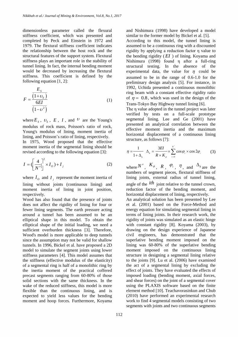
expressed as shown in Figure 1, where:
1P : Vertical overburden earth pressure;
2P : Reaction pressure at the bottom of lining;
3P : Total lateral earth pressure developed at the
crown level of tunnel lining;
4P : Lateral earth pressure developed at the tunnel
invert level;
5P : Self-weight of tunnel lining;
6P : Rock/soil resistance pressure.
Nikkhah et al./ Journal of Mining & Environment, Vol.8, No.1, 2017
114
Here, 6P was assumed to be distributed over a
range of 45-135 degrees with respect to the
vertical direction around the tunnel acting
perpendicular to the tunnel with a parabolic
pattern, as defined by the following equation [8]:
2
6 1 (2 )hP P cos (3)
Here, hP is the rock/soil resistance developed at
the spring line of the tunnel, and is the angle
measured using the vertical direction around the
tunnel. By adopting Winkler’s type of soil/rock
reaction, hPcan be calculated as follows [8]:
h s hP K (4)
where SK is the soil/rock resistance coefficient,
and h is the horizontal displacement at the
spring line of the tunnel.
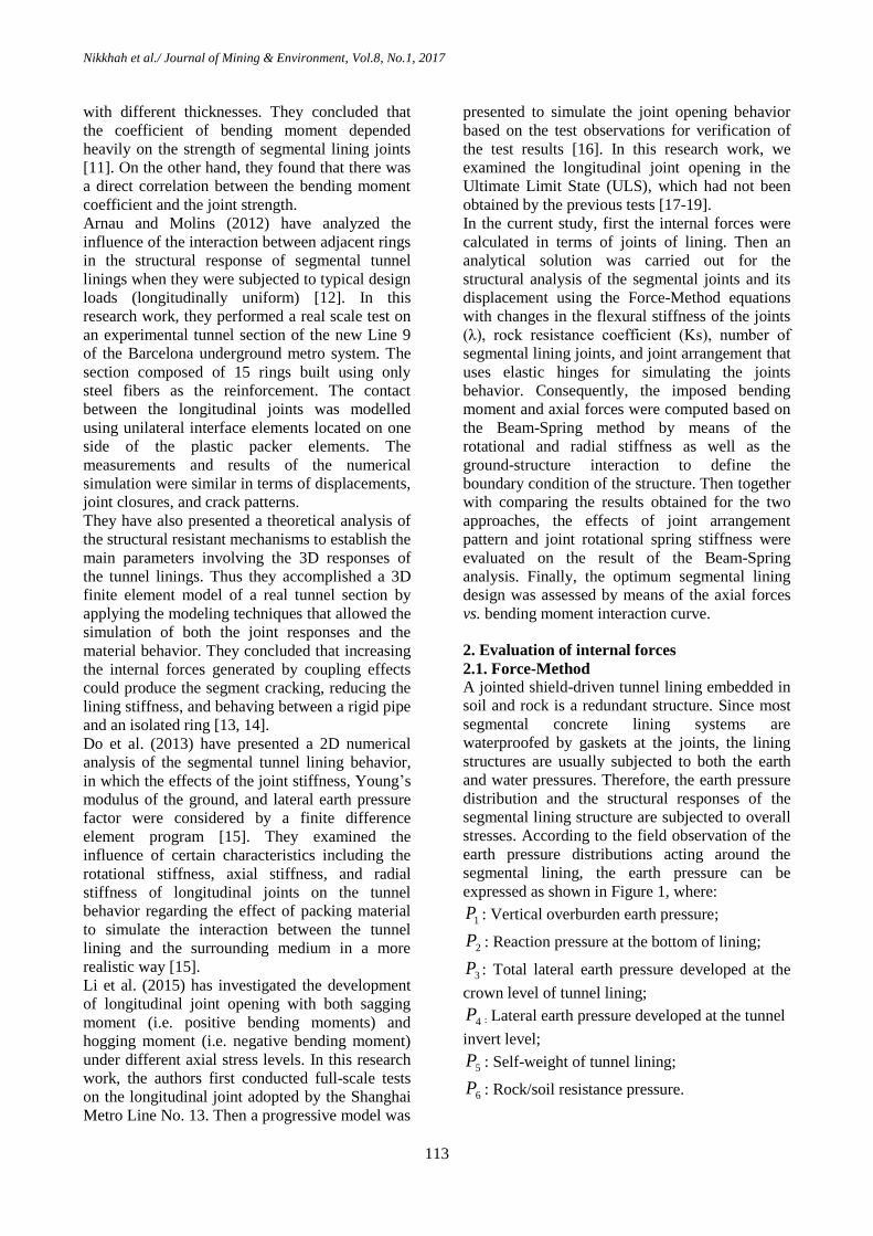
In this research work, a computer program was
designed by the MATLAB software to solve the
proposed analytical equations. Since the
horizontal displacement at the spring line is
unknown at the outset, the soil/rock reaction had
to be determined by iterations. The flowchart of
the iteration process is shown in Figure 2.
The aim of this part of the work was to evaluate
the internal forces of the Chamshir water
conveyance tunnel by changing the flexural
stiffness for the joints ( ),soil resistance
coefficient ( SK),number of segmental joints, and
joint arrangement of segmental lining.
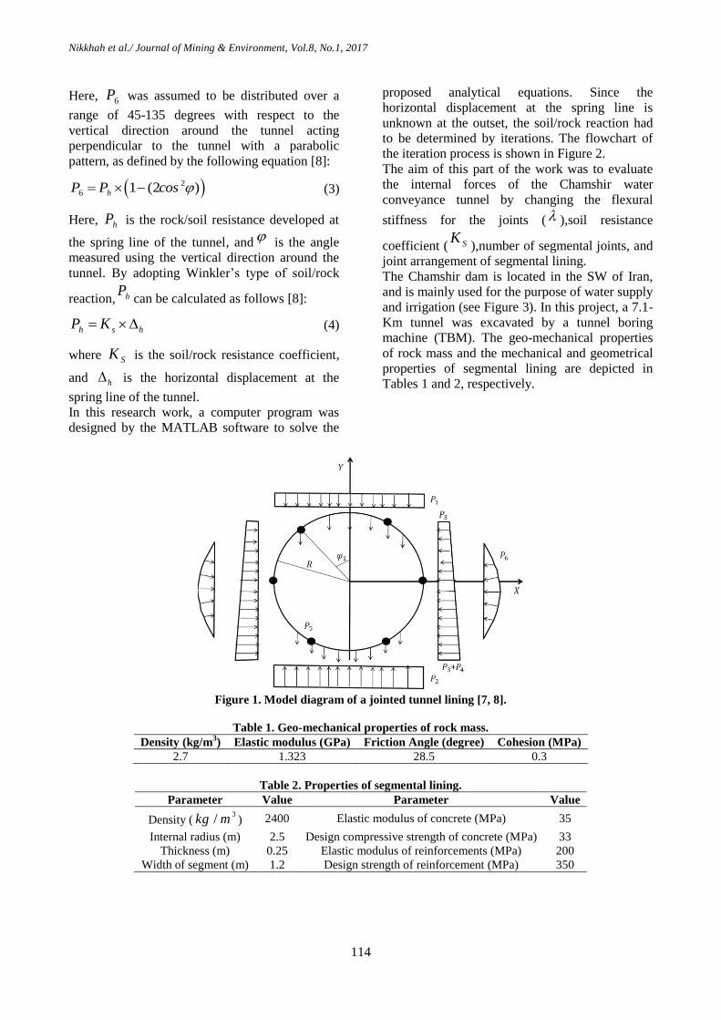
The Chamshir dam is located in the SW of Iran,
and is mainly used for the purpose of water supply
and irrigation (see Figure 3). In this project, a 7.1-
Km tunnel was excavated by a tunnel boring
machine (TBM). The geo-mechanical properties
of rock mass and the mechanical and geometrical
properties of segmental lining are depicted in
Tables 1 and 2, respectively.
Figure 1. Model diagram of a jointed tunnel lining [7, 8].
Table 1. Geo-mechanical properties of rock mass.
Density (kg/m3) Elastic modulus (GPa) Friction Angle (degree) Cohesion (MPa)
2.7 1.323 28.5 0.3
Table 2. Properties of segmental lining.
Parameter Value Parameter Value
Density (3
/kg m ) 2400 Elastic modulus of concrete (MPa) 35
Internal radius (m) 2.5 Design compressive strength of concrete (MPa) 33
Thickness (m) 0.25 Elastic modulus of reinforcements (MPa) 200
Width of segment (m) 1.2 Design strength of reinforcement (MPa) 350
Nikkhah et al./ Journal of Mining & Environment, Vol.8, No.1, 2017
115
Figure 2. Flowchart of computer program [8].
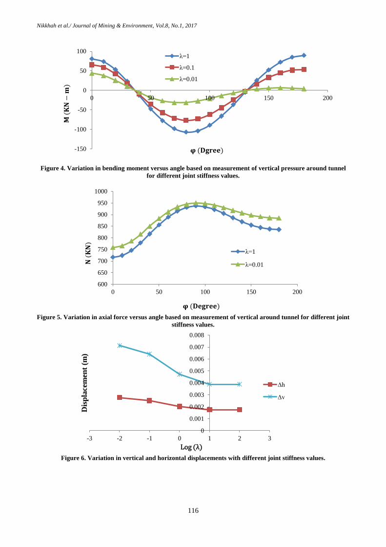
2.1.1. Effect of flexural stiffness of joints
A reduction in the amount of joint flexural
stiffness can reduce the bending moment. Also
with a decline in the flexural stiffness, the
deformation of segments and the imposed
soil/rock resistance pressure would be increased
as well. As a result, the imposed axial forces will
be increased.
In this work, for a better understanding of the joint
effect on the internal forces, the bending moment
and axial forces of the Chamshir segmental tunnel
lining with 6 lining joints were analyzed based on
the Force-Method equations for the three cases
1 , 0.1 , and 0.01 , as depicted in
Figures 4 and 5, respectively. The joint stiffness
coefficient is defined as the ratio of flexural
stiffness of the joints to the flexural rigidity of
lining ) /K EI ). As shown in Figure 4, the
bending moment dropped when the joint stiffness
coefficient was less than 1. On the other hand,
when the rigidity of joints increased, the lining
behavior remained closed to continuous form
thereby increasing the bending moment.
Also, as illustrated in Figure 5, the axial forces of
lining increased for the joint stiffness coefficients
lower than 1. Figure 6 shows the variations in the
vertical and horizontal displacements of the tunnel
with different values of joint stiffness. As it can be
seen, with decrease in the joint stiffness
coefficient, the vertical and horizontal
displacements of segmental lining increased.
More horizontal and vertical displacements were
observed for the joint stiffness coefficients less
than 0.1.
Figure 3. Geological map of studied area [20].
Nikkhah et al./ Journal of Mining & Environment, Vol.8, No.1, 2017
116
Figure 4. Variation in bending moment versus angle based on measurement of vertical pressure around tunnel
for different joint stiffness values.
Figure 5. Variation in axial force versus angle based on measurement of vertical around tunnel for different joint
stiffness values.
Figure 6. Variation in vertical and horizontal displacements with different joint stiffness values.
-150
-100
-50
0
50
100
0 50 100 150 200
λ=1
λ=0.1
λ=0.01
𝛗 (𝐃𝐠𝐫𝐞𝐞)
𝐌 (
𝐊𝐍
−𝐦
)
600
650
700
750
800
850
900
950
1000
0 50 100 150 200
λ=1
λ=0.01
𝛗 (𝐃𝐞𝐠𝐫𝐞𝐞)
𝐍 (
𝐊𝐍
)
0
0.001
0.002
0.003
0.004
0.005
0.006
0.007
0.008
-3 -2 -1 0 1 2 3
Dis
pla
cem
ent
(m)
∆h
∆v
Log (λ)
Nikkhah et al./ Journal of Mining & Environment, Vol.8, No.1, 2017
117
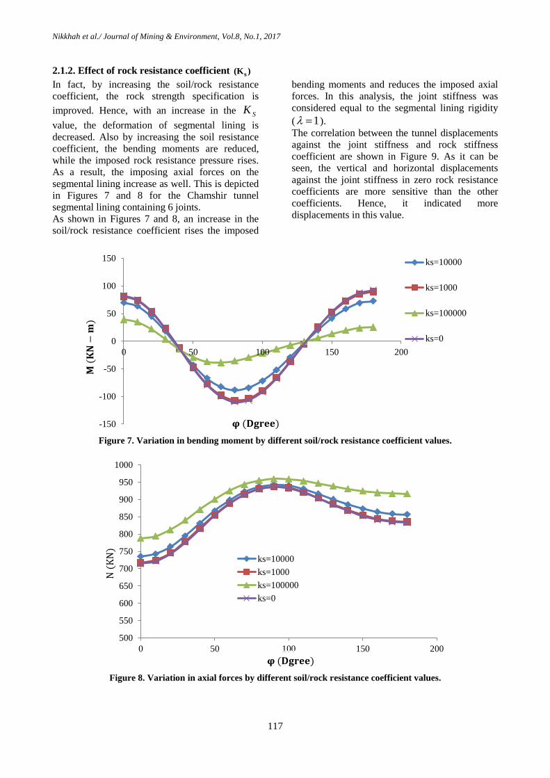
2.1.2. Effect of rock resistance coefficient s(K )
In fact, by increasing the soil/rock resistance
coefficient, the rock strength specification is
improved. Hence, with an increase in the SK
value, the deformation of segmental lining is
decreased. Also by increasing the soil resistance
coefficient, the bending moments are reduced,
while the imposed rock resistance pressure rises.
As a result, the imposing axial forces on the
segmental lining increase as well. This is depicted
in Figures 7 and 8 for the Chamshir tunnel
segmental lining containing 6 joints.
As shown in Figures 7 and 8, an increase in the
soil/rock resistance coefficient rises the imposed
bending moments and reduces the imposed axial
forces. In this analysis, the joint stiffness was
considered equal to the segmental lining rigidity
( 1 ).
The correlation between the tunnel displacements
against the joint stiffness and rock stiffness
coefficient are shown in Figure 9. As it can be
seen, the vertical and horizontal displacements
against the joint stiffness in zero rock resistance
coefficients are more sensitive than the other
coefficients. Hence, it indicated more
displacements in this value.
Figure 7. Variation in bending moment by different soil/rock resistance coefficient values.
Figure 8. Variation in axial forces by different soil/rock resistance coefficient values.
-150
-100
-50
0
50
100
150
0 50 100 150 200
ks=10000
ks=1000
ks=100000
ks=0
𝐌 (
𝐊𝐍
−𝐦
)
𝛗 (𝐃𝐠𝐫𝐞𝐞)
500
550
600
650
700
750
800
850
900
950
1000
0 50 100 150 200
ks=10000
ks=1000
ks=100000
ks=0
𝛗 (𝐃𝐠𝐫𝐞𝐞)
N (
KN
)
Nikkhah et al./ Journal of Mining & Environment, Vol.8, No.1, 2017
118
Figure 9. Segmental lining displacement by different rock resistance coefficient values.
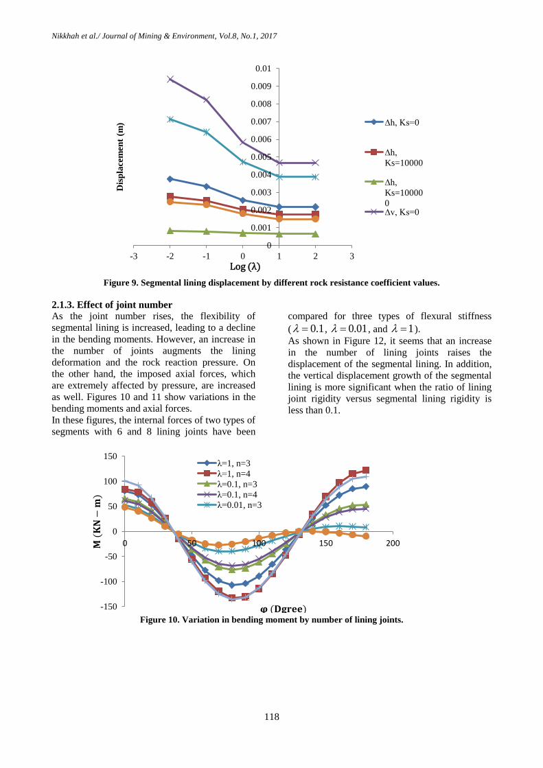
2.1.3. Effect of joint number
As the joint number rises, the flexibility of
segmental lining is increased, leading to a decline
in the bending moments. However, an increase in
the number of joints augments the lining
deformation and the rock reaction pressure. On
the other hand, the imposed axial forces, which
are extremely affected by pressure, are increased
as well. Figures 10 and 11 show variations in the
bending moments and axial forces.
In these figures, the internal forces of two types of
segments with 6 and 8 lining joints have been
compared for three types of flexural stiffness
( 0.1 , 0.01 , and 1 ).
As shown in Figure 12, it seems that an increase
in the number of lining joints raises the
displacement of the segmental lining. In addition,
the vertical displacement growth of the segmental
lining is more significant when the ratio of lining
joint rigidity versus segmental lining rigidity is
less than 0.1.
Figure 10. Variation in bending moment by number of lining joints.
0
0.001
0.002
0.003
0.004
0.005
0.006
0.007
0.008
0.009
0.01
-3 -2 -1 0 1 2 3
Dis
pla
cem
ent
(m) ∆h, Ks=0
∆h,
Ks=10000
∆h,
Ks=10000
0 ∆v, Ks=0
Log (λ)
-150
-100
-50
0
50
100
150
0 50 100 150 200
λ=1, n=3
λ=1, n=4
λ=0.1, n=3
λ=0.1, n=4
λ=0.01, n=3
𝛗 (𝐃𝐠𝐫𝐞𝐞)
𝐌 (
𝐊𝐍
−𝐦
)
Nikkhah et al./ Journal of Mining & Environment, Vol.8, No.1, 2017
119
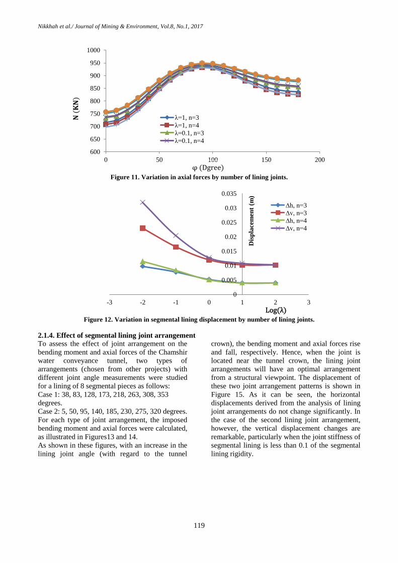
Figure 11. Variation in axial forces by number of lining joints.
Figure 12. Variation in segmental lining displacement by number of lining joints.
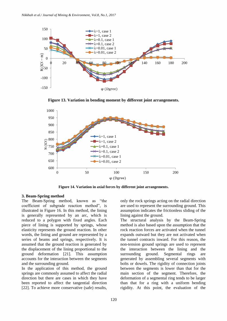
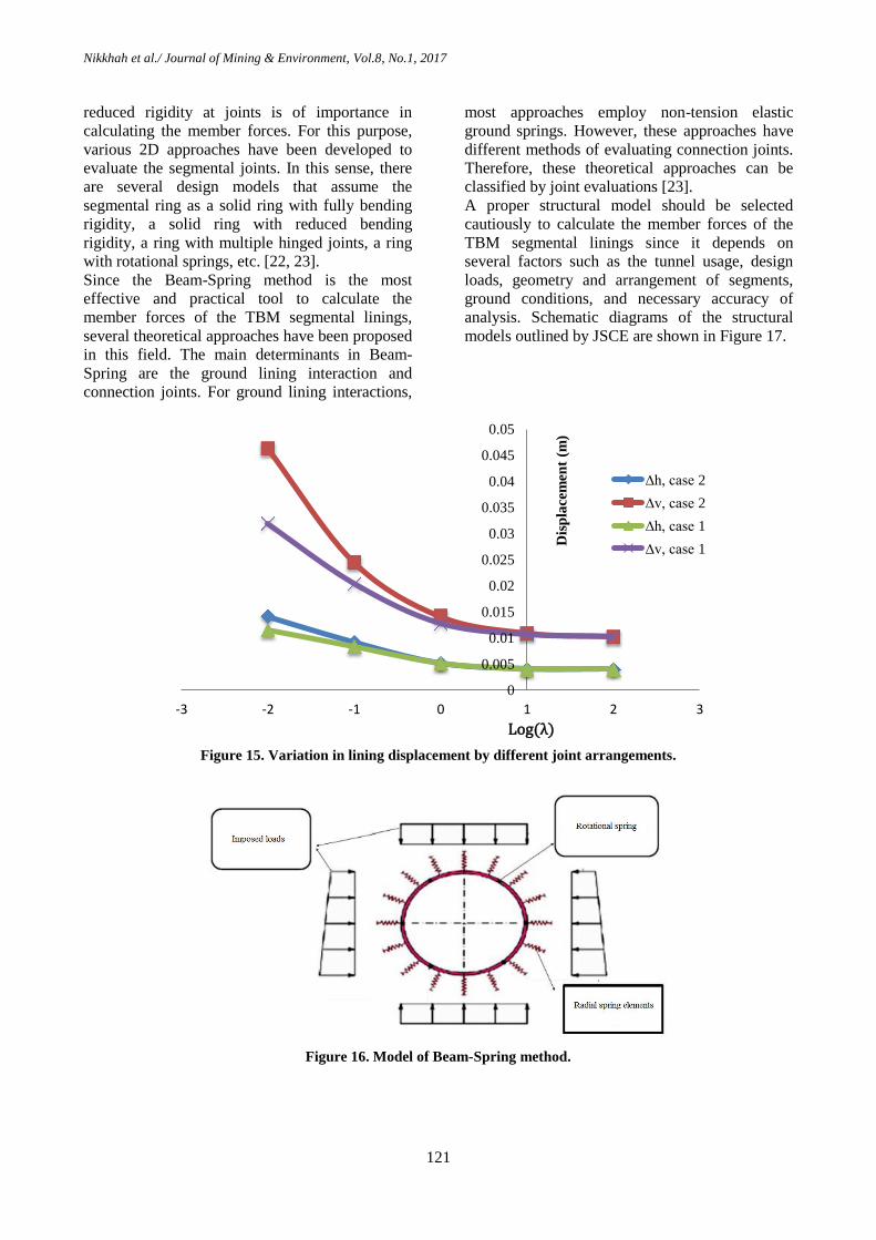
2.1.4. Effect of segmental lining joint arrangement
To assess the effect of joint arrangement on the
bending moment and axial forces of the Chamshir
water conveyance tunnel, two types of
arrangements (chosen from other projects) with
different joint angle measurements were studied
for a lining of 8 segmental pieces as follows:
Case 1: 38, 83, 128, 173, 218, 263, 308, 353
degrees.
Case 2: 5, 50, 95, 140, 185, 230, 275, 320 degrees.
For each type of joint arrangement, the imposed
bending moment and axial forces were calculated,
as illustrated in Figures13 and 14.
As shown in these figures, with an increase in the
lining joint angle (with regard to the tunnel
crown), the bending moment and axial forces rise
and fall, respectively. Hence, when the joint is
located near the tunnel crown, the lining joint
arrangements will have an optimal arrangement
from a structural viewpoint. The displacement of
these two joint arrangement patterns is shown in
Figure 15. As it can be seen, the horizontal
displacements derived from the analysis of lining
joint arrangements do not change significantly. In
the case of the second lining joint arrangement,
however, the vertical displacement changes are
remarkable, particularly when the joint stiffness of
segmental lining is less than 0.1 of the segmental
lining rigidity.
600
650
700
750
800
850
900
950
1000
0 50 100 150 200
λ=1, n=3
λ=1, n=4
λ=0.1, n=3
λ=0.1, n=4
φ (Dgree)
𝐍 (
𝐊𝐍
)
0
0.005
0.01
0.015
0.02
0.025
0.03
0.035
-3 -2 -1 0 1 2 3
Dis
pla
cem
ent
(m)
∆h, n=3
∆v, n=3
∆h, n=4
∆v, n=4
Log(λ)
Nikkhah et al./ Journal of Mining & Environment, Vol.8, No.1, 2017
120
Figure 13. Variation in bending moment by different joint arrangements.
Figure 14. Variation in axial forces by different joint arrangements.
3. Beam-Spring method
The Beam-Spring method, known as “the
coefficient of subgrade reaction method”, is
illustrated in Figure 16. In this method, the lining
is generally represented by an arc, which is
reduced to a polygon with fixed angles. Each
piece of lining is supported by springs, whose
elasticity represents the ground reaction. In other
words, the lining and ground are represented by a
series of beams and springs, respectively. It is
assumed that the ground reaction is generated by
the displacement of the lining proportional to the
ground deformation [21]. This assumption
accounts for the interaction between the segments
and the surrounding ground.
In the application of this method, the ground
springs are commonly assumed to affect the radial
direction but there are cases in which they have
been reported to affect the tangential direction
[22]. To achieve more conservative (safe) results,
only the rock springs acting on the radial direction
are used to represent the surrounding ground. This
assumption indicates the frictionless sliding of the
lining against the ground.
The structural analysis by the Beam-Spring
method is also based upon the assumption that the
rock reaction forces are activated when the tunnel
expands outward but they are not activated when
the tunnel contracts inward. For this reason, the
non-tension ground springs are used to represent
the interaction between the lining and the
surrounding ground. Segmental rings are
generated by assembling several segments with
bolts or dowels. The rigidity of connection joints
between the segments is lower than that for the
main section of the segment. Therefore, the
deformation of a segmental ring tends to be larger
than that for a ring with a uniform bending
rigidity. At this point, the evaluation of the
-150
-100
-50
0
50
100
150
0 20 40 60 80 100 120 140 160 180 200
λ=1, case 1 λ=1, case 2 λ=0.1, case 1 λ=0.1, case 2 λ=0.01, case 1 λ=0.01, case 2
600
650
700
750
800
850
900
950
1000
0 50 100 150 200
λ=1, case 1
λ=1, case 2
λ=0.1, case 1
λ=0.1, case 2
λ=0.01, case 1
λ=0.01, case 2
Nikkhah et al./ Journal of Mining & Environment, Vol.8, No.1, 2017
121
reduced rigidity at joints is of importance in
calculating the member forces. For this purpose,
various 2D approaches have been developed to
evaluate the segmental joints. In this sense, there
are several design models that assume the
segmental ring as a solid ring with fully bending
rigidity, a solid ring with reduced bending
rigidity, a ring with multiple hinged joints, a ring
with rotational springs, etc. [22, 23].
Since the Beam-Spring method is the most
effective and practical tool to calculate the
member forces of the TBM segmental linings,
several theoretical approaches have been proposed
in this field. The main determinants in Beam-
Spring are the ground lining interaction and
connection joints. For ground lining interactions,
most approaches employ non-tension elastic
ground springs. However, these approaches have
different methods of evaluating connection joints.
Therefore, these theoretical approaches can be
classified by joint evaluations [23].
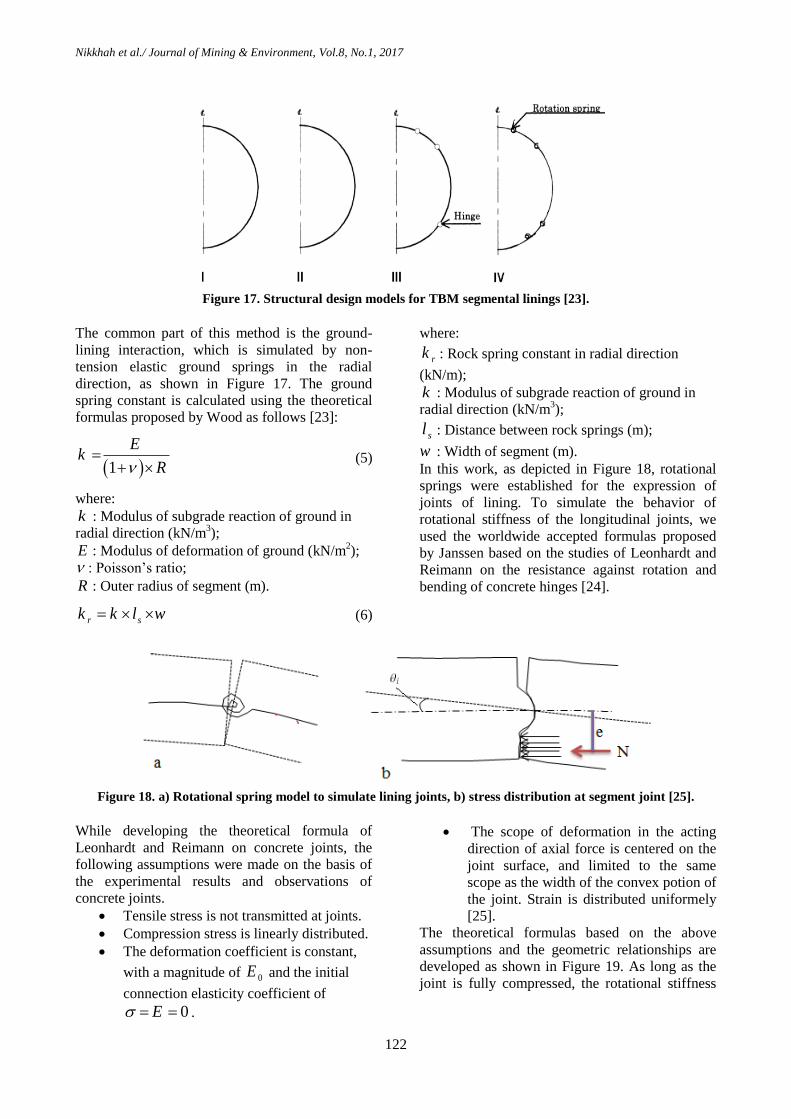
A proper structural model should be selected
cautiously to calculate the member forces of the
TBM segmental linings since it depends on
several factors such as the tunnel usage, design
loads, geometry and arrangement of segments,
ground conditions, and necessary accuracy of
analysis. Schematic diagrams of the structural
models outlined by JSCE are shown in Figure 17.
Figure 15. Variation in lining displacement by different joint arrangements.
Figure 16. Model of Beam-Spring method.
0
0.005
0.01
0.015
0.02
0.025
0.03
0.035
0.04
0.045
0.05
-3 -2 -1 0 1 2 3
Dis
pla
cem
ent
(m)
∆h, case 2
∆v, case 2
∆h, case 1
∆v, case 1
Log(λ)
Nikkhah et al./ Journal of Mining & Environment, Vol.8, No.1, 2017
122
Figure 17. Structural design models for TBM segmental linings [23].
The common part of this method is the ground-
lining interaction, which is simulated by non-
tension elastic ground springs in the radial
direction, as shown in Figure 17. The ground
spring constant is calculated using the theoretical
formulas proposed by Wood as follows [23]:
1
Ek
R
(5)
where:
k : Modulus of subgrade reaction of ground in
radial direction (kN/m3);
E : Modulus of deformation of ground (kN/m2);
: Poisson’s ratio;
R : Outer radius of segment (m).
r sk k l w (6)
where:
rk : Rock spring constant in radial direction
(kN/m);
k : Modulus of subgrade reaction of ground in
radial direction (kN/m3);
sl : Distance between rock springs (m);
w : Width of segment (m).
In this work, as depicted in Figure 18, rotational
springs were established for the expression of
joints of lining. To simulate the behavior of
rotational stiffness of the longitudinal joints, we
used the worldwide accepted formulas proposed
by Janssen based on the studies of Leonhardt and
Reimann on the resistance against rotation and
bending of concrete hinges [24].
Figure 18. a) Rotational spring model to simulate lining joints, b) stress distribution at segment joint [25].
While developing the theoretical formula of
Leonhardt and Reimann on concrete joints, the
following assumptions were made on the basis of
the experimental results and observations of
concrete joints.
Tensile stress is not transmitted at joints.
Compression stress is linearly distributed.
The deformation coefficient is constant,
with a magnitude of 0E and the initial
connection elasticity coefficient of
0E .
The scope of deformation in the acting
direction of axial force is centered on the
joint surface, and limited to the same
scope as the width of the convex potion of
the joint. Strain is distributed uniformely
[25].
The theoretical formulas based on the above
assumptions and the geometric relationships are
developed as shown in Figure 19. As long as the
joint is fully compressed, the rotational stiffness
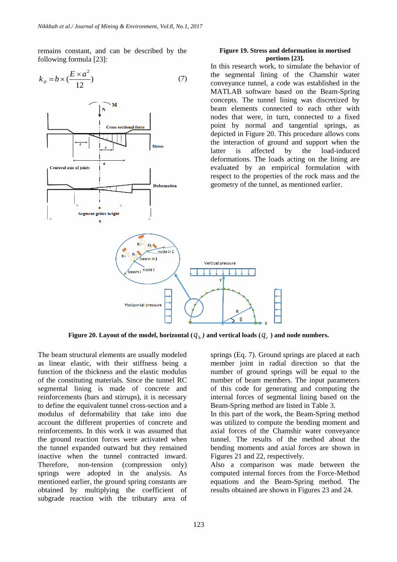
Nikkhah et al./ Journal of Mining & Environment, Vol.8, No.1, 2017
123
remains constant, and can be described by the
following formula [23]:
2
( )12
E ak b
(7)
Figure 19. Stress and deformation in mortised
portions [23].
In this research work, to simulate the behavior of
the segmental lining of the Chamshir water
conveyance tunnel, a code was established in the
MATLAB software based on the Beam-Spring
concepts. The tunnel lining was discretized by
beam elements connected to each other with
nodes that were, in turn, connected to a fixed
point by normal and tangential springs, as
depicted in Figure 20. This procedure allows cons
the interaction of ground and support when the
latter is affected by the load-induced
deformations. The loads acting on the lining are
evaluated by an empirical formulation with
respect to the properties of the rock mass and the
geometry of the tunnel, as mentioned earlier.
Figure 20. Layout of the model, horizontal ( hq ) and vertical loads ( vq ) and node numbers.
The beam structural elements are usually modeled
as linear elastic, with their stiffness being a
function of the thickness and the elastic modulus
of the constituting materials. Since the tunnel RC
segmental lining is made of concrete and
reinforcements (bars and stirrups), it is necessary
to define the equivalent tunnel cross-section and a
modulus of deformability that take into due
account the different properties of concrete and
reinforcements. In this work it was assumed that
the ground reaction forces were activated when
the tunnel expanded outward but they remained
inactive when the tunnel contracted inward.
Therefore, non-tension (compression only)
springs were adopted in the analysis. As
mentioned earlier, the ground spring constants are
obtained by multiplying the coefficient of
subgrade reaction with the tributary area of
springs (Eq. 7). Ground springs are placed at each
member joint in radial direction so that the
number of ground springs will be equal to the
number of beam members. The input parameters
of this code for generating and computing the
internal forces of segmental lining based on the
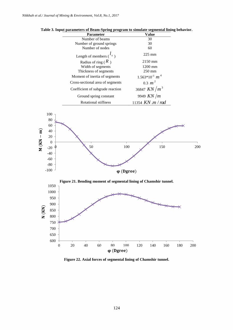
Beam-Spring method are listed in Table 3.
In this part of the work, the Beam-Spring method
was utilized to compute the bending moment and
axial forces of the Chamshir water conveyance
tunnel. The results of the method about the
bending moments and axial forces are shown in
Figures 21 and 22, respectively.
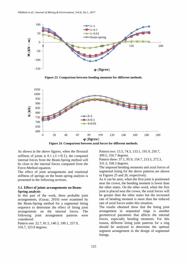
Also a comparison was made between the
computed internal forces from the Force-Method
equations and the Beam-Spring method. The
results obtained are shown in Figures 23 and 24.
Nikkhah et al./ Journal of Mining & Environment, Vol.8, No.1, 2017
124
Table 3. Input parameters of Beam-Spring program to simulate segmental lining behavior.
Parameter Value
Number of beams 30
Number of ground springs 30
Number of nodes 60
Length of members ( sl)
225 mm
Radius of ring ( R ) 2150 mm
Width of segments 1200 mm
Thickness of segments 250 mm
Moment of inertia of segments 1.563*10-3
4m
Cross-sectional area of segments 0.3 2m
Coefficient of subgrade reaction 36847 3KN m
Ground spring constant 9949 KN m
Rotational stiffness 11354 . /KN m rad
Figure 21. Bending moment of segmental lining of Chamshir tunnel.
Figure 22. Axial forces of segmental lining of Chamshir tunnel.
-100
-80
-60
-40
-20
0
20
40
60
80
100
0 50 100 150 200
𝛗 (𝐃𝐠𝐫𝐞𝐞)
𝐌 (
𝐊𝐍
−𝐦
)
600
650
700
750
800
850
900
950
1000
1050
0 20 40 60 80 100 120 140 160 180 200
𝐍 (
𝐊𝐍
)
𝛗 (𝐃𝐠𝐫𝐞𝐞)
Nikkhah et al./ Journal of Mining & Environment, Vol.8, No.1, 2017
125
Figure 23. Comparison between bending moments for different methods.
Figure 24. Comparison between axial forces for different methods.
As shown in the above figures, when the flextural
stiffness of joints is 0.1 ( 0.1 ), the computed
internal forces from the Beam-Spring method will
be close to the internal forces computed from the
Force-Method equation.
The effect of joint arrangements and rotational
stiffness of springs on the beam spring analysis is
presented in the following sections.
3.1. Effect of joints arrangements on Beam-
Spring analysis
In this part of the work, three probable joint
arrangements, (Guray, 2010) were examined by
the Beam-Spring method for a segmental lining
sequence to determine the effect of lining joint
arrangements on the internal forces. The
following joint arrangement patterns were
considered:
Pattern one: 22.7, 81.5, 140.3, 199.1, 257.9,
316.7, 323.9 degrees.
Pattern two: 15.5, 74.3, 133.1, 191.9, 250.7,
309.5, 316.7 degrees.
Pattern three: 37.1, 95.9, 154.7, 213.5, 272.3,
331.3, 338.3 degrees.
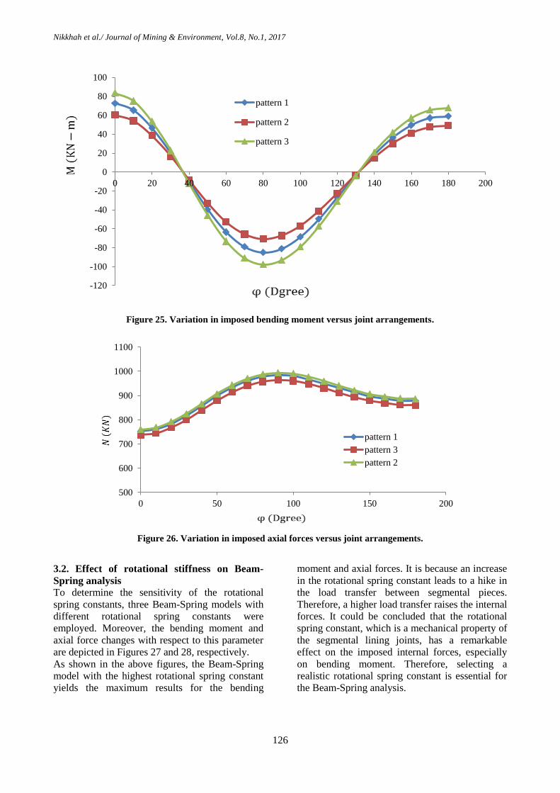
The imposed bending moments and axial forces of
segmental lining for the above patterns are shown
in Figures 25 and 26, respectively.
As it can be seen, when the first joint is positioned
near the crown, the bending moment is lower than
the other states. On the other word, when the first
joint is placed near the crown, the axial forces will
be greater than the other states but the increased
rate of bending moment is more than the reduced
rate of axial forces under this situation.
The results obtained show that the lining joint
arrangement in sequential rings is another
geometrical parameter that affects the internal
forces, especially bending moments. For this
reason, different lining joint patterns for a ring
should be analyzed to determine the optimal
segment arrangement in the design of segmental
linings.
-150
-100
-50
0
50
100
0 50 100 150 200
λ=1
λ=0.1
λ=0.01
beam-spring
𝛗 (𝐃𝐠𝐫𝐞𝐞)
𝐌 (
𝐊𝐍
−𝐦
)
600
650
700
750
800
850
900
950
1000
1050
0 20 40 60 80 100 120 140 160 180 200
λ=1 λ=0.1 λ=0.01
𝐍 (
𝐊𝐍
)
𝛗 (𝐃𝐠𝐫𝐞𝐞)
Nikkhah et al./ Journal of Mining & Environment, Vol.8, No.1, 2017
126
Figure 25. Variation in imposed bending moment versus joint arrangements.
Figure 26. Variation in imposed axial forces versus joint arrangements.
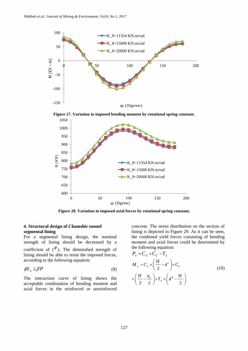
3.2. Effect of rotational stiffness on Beam-
Spring analysis
To determine the sensitivity of the rotational
spring constants, three Beam-Spring models with
different rotational spring constants were
employed. Moreover, the bending moment and
axial force changes with respect to this parameter
are depicted in Figures 27 and 28, respectively.
As shown in the above figures, the Beam-Spring
model with the highest rotational spring constant
yields the maximum results for the bending
moment and axial forces. It is because an increase
in the rotational spring constant leads to a hike in
the load transfer between segmental pieces.
Therefore, a higher load transfer raises the internal
forces. It could be concluded that the rotational
spring constant, which is a mechanical property of
the segmental lining joints, has a remarkable
effect on the imposed internal forces, especially
on bending moment. Therefore, selecting a
realistic rotational spring constant is essential for
the Beam-Spring analysis.
-120
-100
-80
-60
-40
-20
0
20
40
60
80
100
0 20 40 60 80 100 120 140 160 180 200
pattern 1
pattern 2
pattern 3
500
600
700
800
900
1000
1100
0 50 100 150 200
pattern 1
pattern 3
pattern 2
Nikkhah et al./ Journal of Mining & Environment, Vol.8, No.1, 2017
127
Figure 27. Variation in imposed bending moment by rotational spring constant.
Figure 28. Variation in imposed axial forces by rotational spring constant.
4. Structural design of Chamshir tunnel
segmental lining
For a segmental lining design, the nominal
strength of lining should be decreased by a
coefficient of ( ). The diminished strength of
lining should be able to resist the imposed forces,
according to the following equation:
nS P (8)
The interaction curve of lining shows the
acceptable combination of bending moment and
axial forces in the reinforced or unreinforced
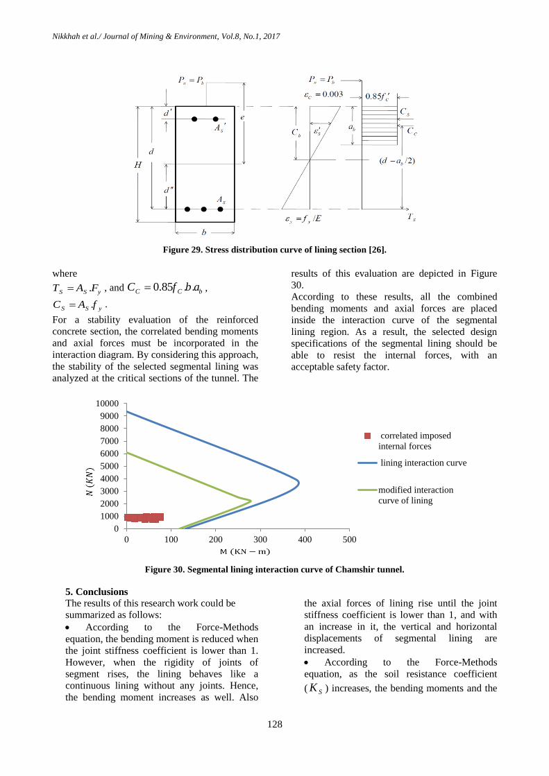
concrete. The stress distribution on the section of
lining is depicted in Figure 29. As it can be seen,
the combined yield forces consisting of bending
moment and axial forces could be determined by
the following equation:
n S C SP C C T
2
2 2 2
n S C
b
S
HM C d C
aH HT d
(10)
-150
-100
-50
0
50
100
0 50 100 150 200
K_θ=11354 KN.m/rad
K_θ=15000 KN.m/rad
K_θ=20000 KN.m/rad
600
650
700
750
800
850
900
950
1000
1050
0 50 100 150 200
K_θ=11354 KN.m/rad
K_θ=15000 KN.m/rad
K_θ=20000 KN.m/rad
Nikkhah et al./ Journal of Mining & Environment, Vol.8, No.1, 2017
128
Figure 29. Stress distribution curve of lining section [26].
where
.S S yT A F , and 0.85 . .C C bC f b a ,
.S S yC A f .
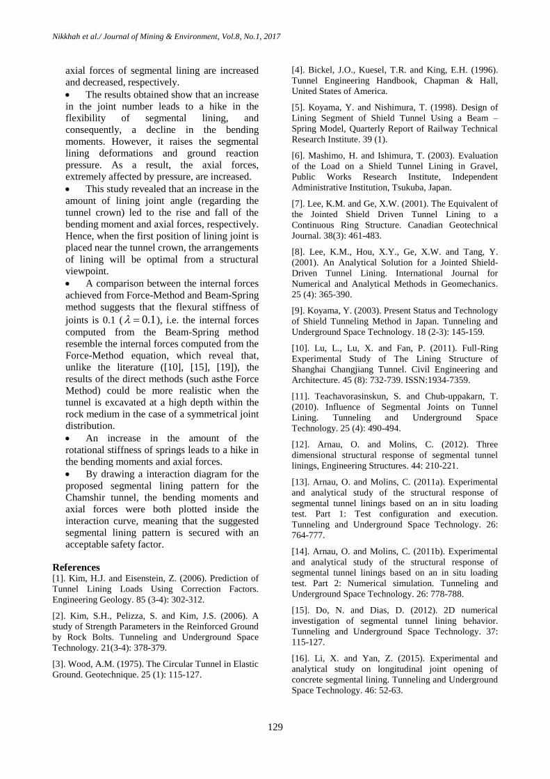
For a stability evaluation of the reinforced
concrete section, the correlated bending moments
and axial forces must be incorporated in the
interaction diagram. By considering this approach,
the stability of the selected segmental lining was
analyzed at the critical sections of the tunnel. The
results of this evaluation are depicted in Figure
30.
According to these results, all the combined
bending moments and axial forces are placed
inside the interaction curve of the segmental
lining region. As a result, the selected design
specifications of the segmental lining should be
able to resist the internal forces, with an
acceptable safety factor.
Figure 30. Segmental lining interaction curve of Chamshir tunnel.
5. Conclusions
The results of this research work could be
summarized as follows:
According to the Force-Methods
equation, the bending moment is reduced when
the joint stiffness coefficient is lower than 1.
However, when the rigidity of joints of
segment rises, the lining behaves like a
continuous lining without any joints. Hence,
the bending moment increases as well. Also
the axial forces of lining rise until the joint
stiffness coefficient is lower than 1, and with
an increase in it, the vertical and horizontal
displacements of segmental lining are
increased.
According to the Force-Methods
equation, as the soil resistance coefficient
( SK ) increases, the bending moments and the
0
1000
2000
3000
4000
5000
6000
7000
8000
9000
10000
0 100 200 300 400 500
correlated imposed
internal forces
lining interaction curve
modified interaction
curve of lining
Nikkhah et al./ Journal of Mining & Environment, Vol.8, No.1, 2017
129
axial forces of segmental lining are increased
and decreased, respectively.
The results obtained show that an increase
in the joint number leads to a hike in the
flexibility of segmental lining, and
consequently, a decline in the bending
moments. However, it raises the segmental
lining deformations and ground reaction
pressure. As a result, the axial forces,
extremely affected by pressure, are increased.
This study revealed that an increase in the
amount of lining joint angle (regarding the
tunnel crown) led to the rise and fall of the
bending moment and axial forces, respectively.
Hence, when the first position of lining joint is
placed near the tunnel crown, the arrangements
of lining will be optimal from a structural
viewpoint.
A comparison between the internal forces
achieved from Force-Method and Beam-Spring
method suggests that the flexural stiffness of
joints is 0.1 ( 0.1 ), i.e. the internal forces
computed from the Beam-Spring method
resemble the internal forces computed from the
Force-Method equation, which reveal that,
unlike the literature ([10], [15], [19]), the
results of the direct methods (such asthe Force
Method) could be more realistic when the
tunnel is excavated at a high depth within the
rock medium in the case of a symmetrical joint
distribution.
An increase in the amount of the
rotational stiffness of springs leads to a hike in
the bending moments and axial forces.
By drawing a interaction diagram for the
proposed segmental lining pattern for the
Chamshir tunnel, the bending moments and
axial forces were both plotted inside the
interaction curve, meaning that the suggested
segmental lining pattern is secured with an
acceptable safety factor.
References [1]. Kim, H.J. and Eisenstein, Z. (2006). Prediction of
Tunnel Lining Loads Using Correction Factors.
Engineering Geology. 85 (3-4): 302-312.
[2]. Kim, S.H., Pelizza, S. and Kim, J.S. (2006). A
study of Strength Parameters in the Reinforced Ground
by Rock Bolts. Tunneling and Underground Space
Technology. 21(3-4): 378-379.
[3]. Wood, A.M. (1975). The Circular Tunnel in Elastic
Ground. Geotechnique. 25 (1): 115-127.
[4]. Bickel, J.O., Kuesel, T.R. and King, E.H. (1996).
Tunnel Engineering Handbook, Chapman & Hall,
United States of America.
[5]. Koyama, Y. and Nishimura, T. (1998). Design of
Lining Segment of Shield Tunnel Using a Beam –
Spring Model, Quarterly Report of Railway Technical
Research Institute. 39 (1).
[6]. Mashimo, H. and Ishimura, T. (2003). Evaluation
of the Load on a Shield Tunnel Lining in Gravel,
Public Works Research Institute, Independent
Administrative Institution, Tsukuba, Japan.
[7]. Lee, K.M. and Ge, X.W. (2001). The Equivalent of
the Jointed Shield Driven Tunnel Lining to a
Continuous Ring Structure. Canadian Geotechnical
Journal. 38(3): 461-483.
[8]. Lee, K.M., Hou, X.Y., Ge, X.W. and Tang, Y.
(2001). An Analytical Solution for a Jointed Shield-
Driven Tunnel Lining. International Journal for
Numerical and Analytical Methods in Geomechanics.
25 (4): 365-390.
[9]. Koyama, Y. (2003). Present Status and Technology
of Shield Tunneling Method in Japan. Tunneling and
Underground Space Technology. 18 (2-3): 145-159.
[10]. Lu, L., Lu, X. and Fan, P. (2011). Full-Ring
Experimental Study of The Lining Structure of
Shanghai Changjiang Tunnel. Civil Engineering and
Architecture. 45 (8): 732-739. ISSN:1934-7359.
[11]. Teachavorasinskun, S. and Chub-uppakarn, T.
(2010). Influence of Segmental Joints on Tunnel
Lining. Tunneling and Underground Space
Technology. 25 (4): 490-494.
[12]. Arnau, O. and Molins, C. (2012). Three
dimensional structural response of segmental tunnel
linings, Engineering Structures. 44: 210-221.
[13]. Arnau, O. and Molins, C. (2011a). Experimental
and analytical study of the structural response of
segmental tunnel linings based on an in situ loading
test. Part 1: Test configuration and execution.
Tunneling and Underground Space Technology. 26:
764-777.
[14]. Arnau, O. and Molins, C. (2011b). Experimental
and analytical study of the structural response of
segmental tunnel linings based on an in situ loading
test. Part 2: Numerical simulation. Tunneling and
Underground Space Technology. 26: 778-788.
[15]. Do, N. and Dias, D. (2012). 2D numerical
investigation of segmental tunnel lining behavior.
Tunneling and Underground Space Technology. 37:
115-127.
[16]. Li, X. and Yan, Z. (2015). Experimental and
analytical study on longitudinal joint opening of
concrete segmental lining. Tunneling and Underground
Space Technology. 46: 52-63.
Nikkhah et al./ Journal of Mining & Environment, Vol.8, No.1, 2017
130
[17]. Zhong, X., Zhu, W., Huang, Z. and Han, Y.
(2006). Effect of joint structure on joint stiffness for
shield tunnel lining. Tunneling and Underground Space
Technology. 21: 406- 407.
[18]. Yu, H.T., Yuan, Y., Qiao, Z.Z., Gu, Y., Yang,
Z.H. and Li, X.D. (2013). Seismic analysis of a long
tunnel based on multi-scale method. Engineering
Structure. 49: 572-587.
[19]. El Naggar, H. and Hinchberger, S.D. (2008). An
analytical solution for jointed tunnellinings in elastic
soil or rock. Canadian Geotech. Journal. 45 (11): 1572-
1593.
[20]. Iranian Oil Operating Companies (IOOC). (1996).
Gachsaran Geological Map. 1: 100,000.
[21]. AFTES – WG7, Considerations on the Usual
Methods of Tunnel Lining Design. (1993). French
Tunneling and Underground Engineering Association,
Working Group No. 7 - Temporary Supports and
Permanent Lining.
[22]. JSCE, Japanese Standard for Shield
Tunneling.(1996). Japan Society of Civil Engineers,
The third edition, Tokyo.
[23]. Guray, A. (2010). Evaluation of structural
analysis used for the design of TBM segmental linings,
Master thesis of civil engineering, Middle East
Technical University.
[24]. Klappers, C., Gruebl, F. and Ostermeier, B.
(1999). Structural Analysis of Segmental Lining –
Coupled Beam and Spring Analyses Versus 3D FEM
Calculations with Shell Elements, Tunneling and
Underground Space Technology. 21 ( 3-4).
[25]. Wang, J.J. (2005). The Design Considerations for
the Segmental Lining of the Hsuehshan Tunnel,
International Symposium on Design, Construction and
Operation of Long Tunnels, Taiwan.
[26]. Tahouni, S. (2004). Reinforce concrete structure
design. (in Persian).
5931، سال اولم، شماره تشهدوره زیست، پژوهشی معدن و محیط -و همکاران/ نشریه علمینیکخواه
روین -میله و روش -ی پوشش سگمنت بتنی پوشش تونل با استفاده از روش فنرا سازهارزیابی تحلیل
تونل انتقال آب چم شیر( :مطالعه موردی)
2امید خادم حسینی و 1، شکراهلل زارع1، سید سعید موسوی 1*مجید نیکخواه
دانشگاه صنعتی شاهرود، ایران دانشکده مهندسی معدن، نفت و ژئوفیزیک، -1
دانشکده مهندسی عمران، دانشگاه صنعتی شاهرود، ایران -2
01/5/0252، پذیرش 02/55/0251ارسال
[email protected]* نویسنده مسئول مکاتبات:
چکیده:
مقدار مشخصی ممان خمشی، نیروهای محووری و برشوی را تحمول نماینود بوه لوور لوی در توانند یم ها تونلهای پوشش بتنی اتصاالت و درزهای بین سگمنت
یوا صولبیت اتصواالت برحسو بایود هوا آن، اتصاالت به صورت لوالهای االستیک و فنرهای دورانی مدل شده و صولبیت ها تونلهای بتنی ی سگمنتا سازهلراحی
اهش یابند و در نتیجه لراحان تونل برای انتخوا طععوات پوشوش بتنوی بوا توانند یموارد بر پوشش بتنی بنابراین ممان خمشی ؛ی دورانی بیان شوندها یسخت
بتنی تونل با توجه به تغییرات سختی خمشی اتصاالت، ضوری ساخته شیپی طععات ا سازههزینه متر آزادی عمل بیشتری خواهند داشت در این تحقیق، تحلیل
نیورو انجواگ فرفتوه اسوت سوان مموان خمشوی و -ها با اسوتااده از معوادالت روش ت طععات پوشش بتنی و آرایش اتصاالت سگمنتمقاومت خاک، تعداد اتصاال
محاسبه فردیده و بوا نتوای روند یمی نیروهای داخلی طععات پوشش بتنی بکار ها لیتحلمیله ه به لور وسیعی در -ی محوری ایجاد شده توسط روش فنرروهاین
میلوه ارزیوابی -آمده از تحلیل فنر دست به در ادامه اثرات الگوی آرایش اتصاالت و سختی فنر دورانی با توجه به نتای اند شدهنیرو مقایسه -حاصل از معادالت روش
های خمشی و نیروهای محوری مورد بررسوی واطو اندر نش ممان با استااده از دیافراگ ی بهینه لراحی طععات پوشش بتن مسلحها مشخصهشده است در نهایت
یک معالعه مووردی در مقابول عنوان بههای بتنی پوشش تونل انتقال آ چم شیر ) ه الگوی ارائه شده برای سگمنت دهند یمآمده نشان دست به نتای اند شده
طراردادندابل طبولی با فشارهای خارجی وارد بر طععات پوشش بتنی، در وضعیت ایمنی ط
میله، تونل چم شیر -ی، روش فنرا سازهتونل، لراحی سگمنت پوششی، تحلیل کلمات کلیدی: