Embed Size (px)
Citation preview
Lehigh UniversityLehigh Preserve
Theses and Dissertations
2001
Evaluation of steel bridge truss systems byconversion to equivalent box girdersGokhan GelisenLehigh University
Follow this and additional works at: http://preserve.lehigh.edu/etd
This Thesis is brought to you for free and open access by Lehigh Preserve. It has been accepted for inclusion in Theses and Dissertations by anauthorized administrator of Lehigh Preserve. For more information, please contact [email protected].
Recommended CitationGelisen, Gokhan, "Evaluation of steel bridge truss systems by conversion to equivalent box girders" (2001). Theses and Dissertations.Paper 685.
{
Gelisen, Gokhan ·
I:VALUATION OF .STI:I:L BRIDGI:, . .
\ .
TRiUSS.SYSTI:MS BY ..CONVI:RSION
, .
TO... .
June 2001
EVALUATION OF STEEL BRIDGE TRUSS SYSTEMS BY CONVERSION
TO EQUIVALENT BOX GIRDERS
by
Gokhan Gelisen
A Thesis
Presented to the Graduate and Research Committee
ofLehigh University
in Candidacy for the Degree of
Master of Science
m
Department of Civil and Environmental Engineering
Lehigh University
Date: May 3, 2001
ACKNOWLEDGEMENT
The author is deeply indebted to Professor Ben T. Yen, thesis supervisor, for
his continued guidance, encouragement and cooperation in the preparation of this
thesis. The interest and guidance of Professor John L. Wilson, is gratefully
acknowledged. Last but not the least, appreciation is extended to the entire faculty,
staff and fellow students in Department of Civil and Environmental Engineering at
Lehigh University for all their help.
111
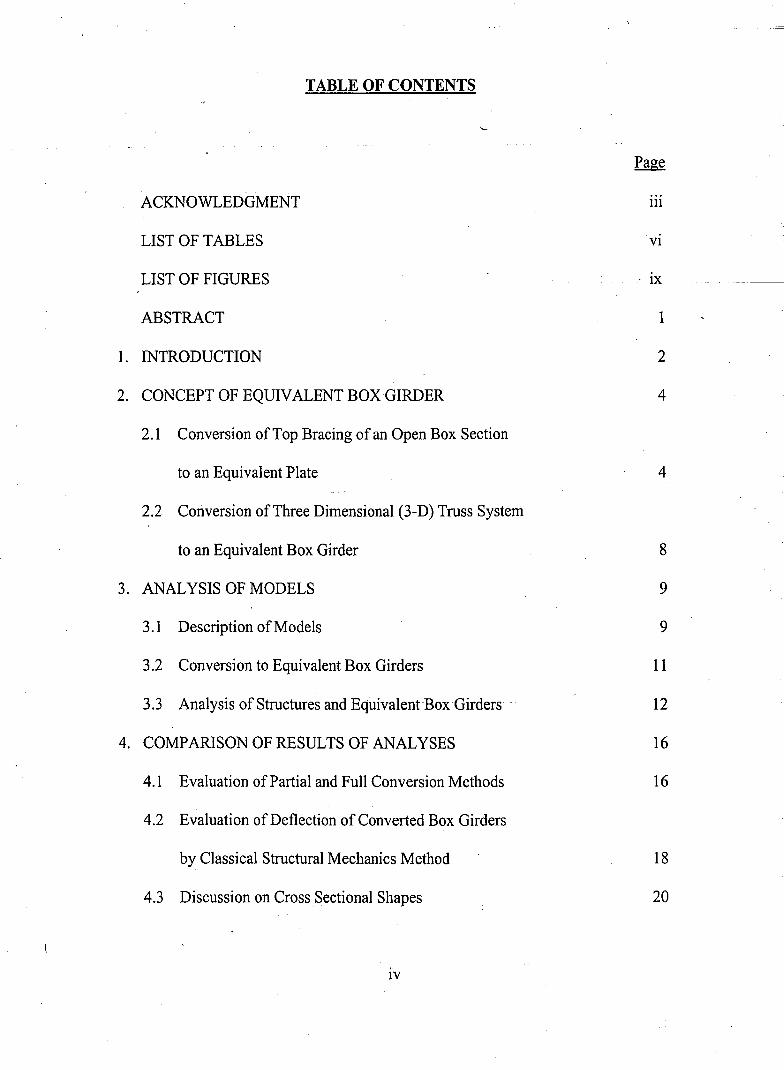
TABLE OF CONTENTS
Page
ACKNOWLEDGMENT 111
LIST OF TABLES VI
LIST OF FIGURES . IX -_._--
ABSTRACT 1
1. INTRODUCTION 2
2. CONCEPT OF EQUIVALENT BOX GIRDER 4
2.1 Conversion of Top Bracing of an Open Box Section
to an Equivalent Plate 4
2.2 Conversion ofThree Dimensional (3-D) Truss System
to an Equivalent Box Girder 8
3. ANALYSIS OF MODELS 9
3.1 Description ofModels 9
3.2 Conversion to Equivalent Box Girders 11
3.3 Analysis of Structures and Equivalent Box Girders - ----I-2--
4. COMPARISON OF RESULTS OF ANALYSES 16
4.1 Evaluation of Partial and Full Conversion Methods 16
4.2 Evaluation of Deflection of Converted Box Girders
by Classical Structural Mechanics Method 18
4.3 Discussion on Cross Sectional Shapes 20
IV
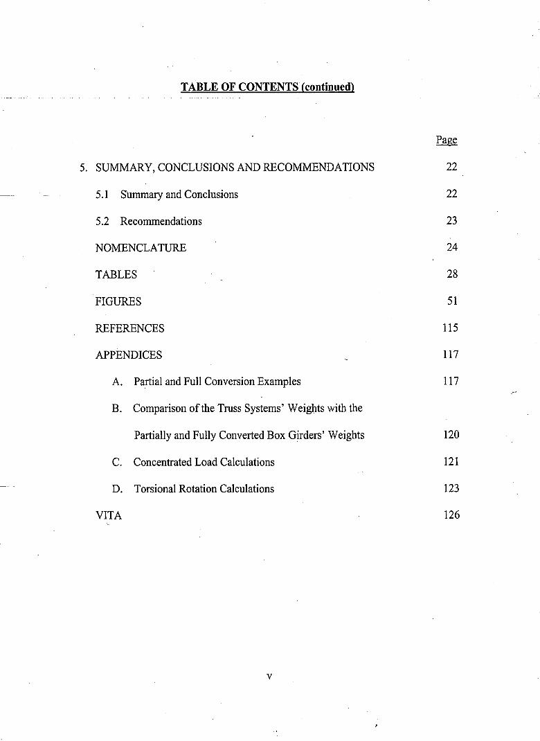
TABLE OF CONTENTS (continued)
5. SUMMARY, CONCLUSIONS AND RECOMMENDATIONS
5.1 Summary and Conclusions
5.2 Recommendations
NOMENCLATURE
TABLES
FIGURES
REFERENCES
APPENDICES
A. Partial and Full Conversion Examples
B. Comparison of the Truss Systems' Weights with the
Partially and Fully Converted Box Girders' Weights
C. Concentrated Load Calculations
D. Torsional Rotation Calculations
VITA
v
Page
22
22
23
24
28
51
115
117
117
120
121
123
126
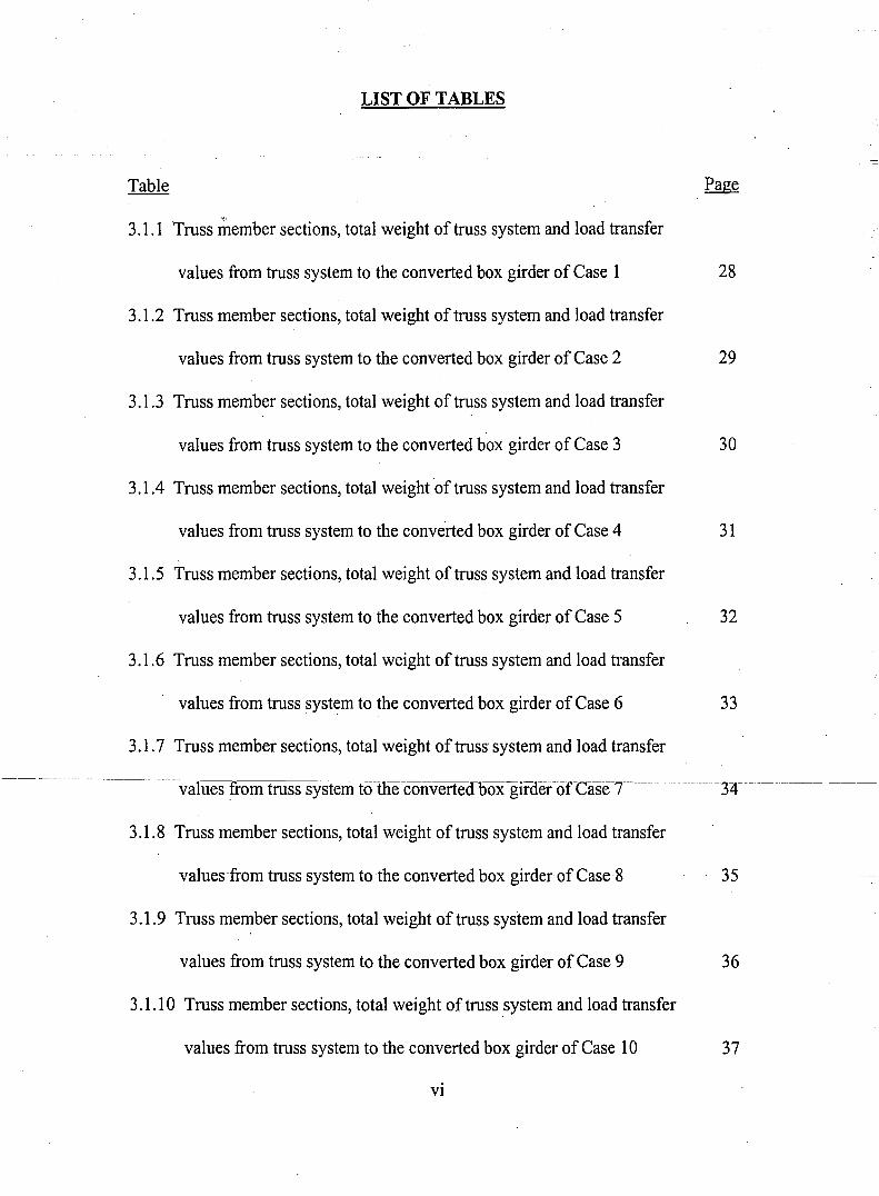
LIST OF TABLES
Table Page
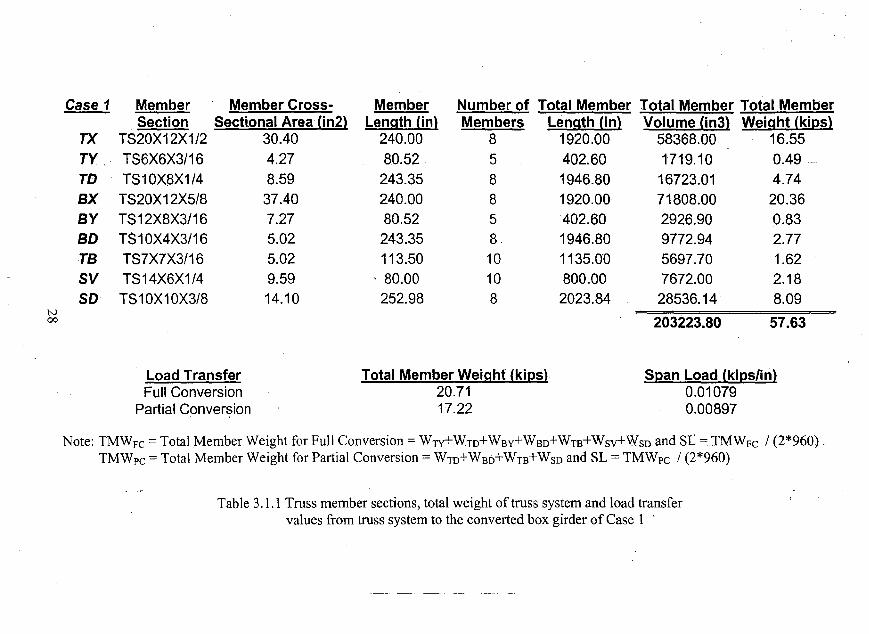
3.1.1 Truss member sections, total weight of truss system and load transfer
values from truss system to the converted box girder of Case 1 28
3.1.2 Truss member sections, total weight of truss system and load transfer
values from truss system to the converted box girder of Case 2 29
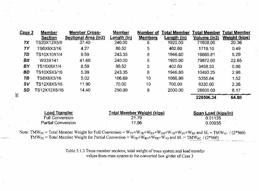
3.1.3 Truss member sections, total weight of truss system and load transfer
values from truss system to the converted box girder of Case 3 30
3.1.4 Truss member sections, total weight of truss system and load transfer
values from truss system to the converted box girder of Case 4 31
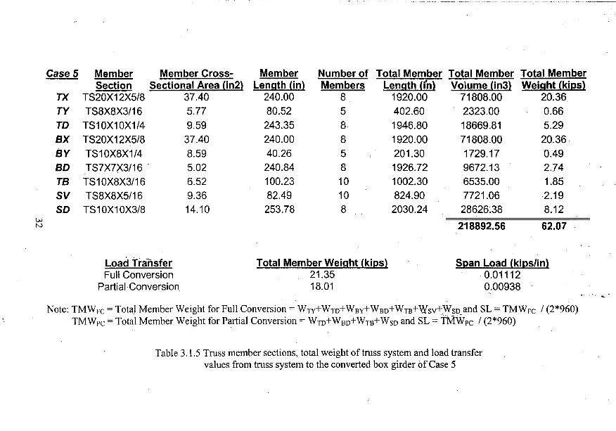
3.1.5 Truss member sections, total weight of truss system and load transfer
values from truss system to the converted box girder of Case 5 32
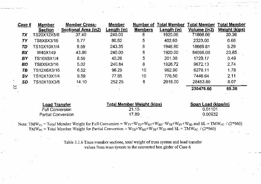
3.1.6 Truss member sections, total weight of truss system and load transfer
values from truss system to the converted box girder of Case 6 33
3.1.7 Truss member sections, total weight of truss' system and load transfer
--- - --_._--~- .
values from truss systemfo-the--converte<r15Oxgirdef-orCase7---- -- -32r-----~-----
3.1.8 Truss member sections, total weight of truss system and load transfer
values from truss system to the converted box·girder of Case 8 35
3.1.9 Truss member sections, total weight of truss system and load transfer
values from truss system to the converted box girder of Case 9 36
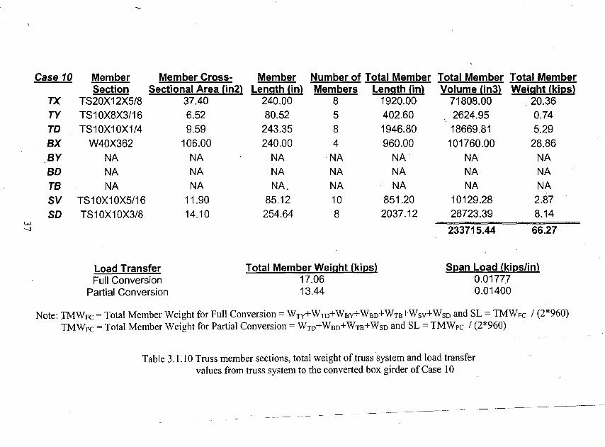
3.1.10 Truss member sections, total weight of truss system and load transfer
values from truss system to the converted box girder of Case 10 37
VI
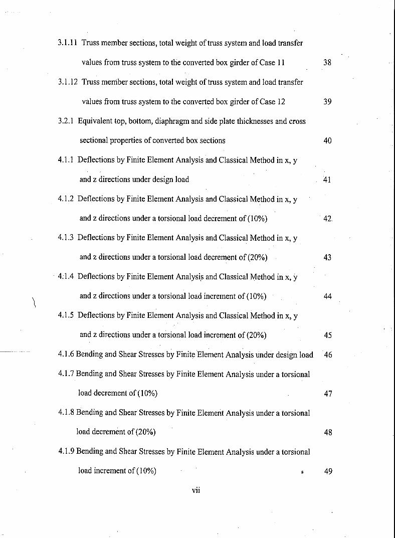
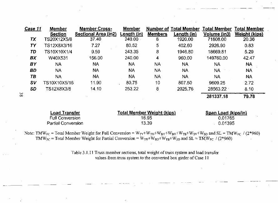
3.1.11 Truss member sections, total weight of truss system and load transfer
values from truss system to the converted box girder of Case 11 38
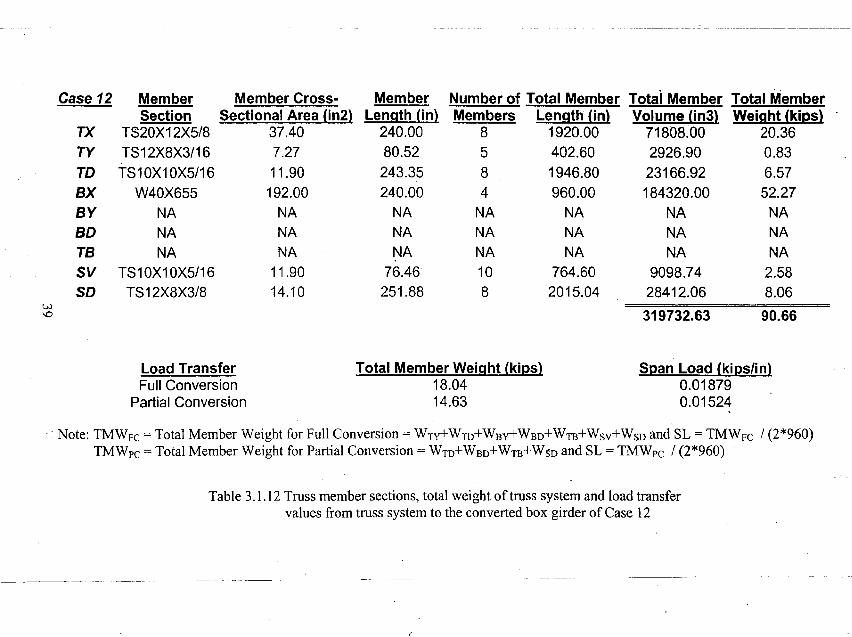
3.1.12 Truss member sections, total weight of truss system and load transfer
values from truss system to the converted box girder of Case 12 39
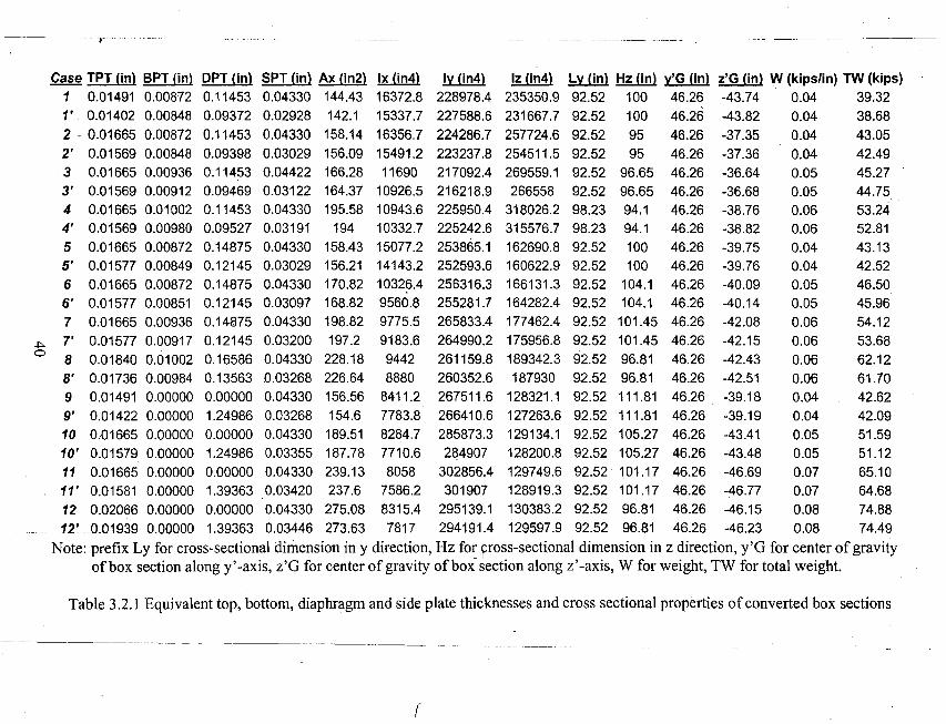
3.2.1 Equivalent top, bottom, diaphragm and side plate thicknesses and cross
sectional properties of converted box sections 40
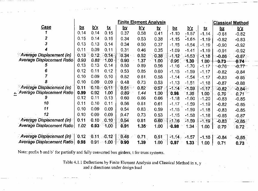
4.1.1 Deflections by Finite Element Analysis and Classical Method in x, y
and z directions under design load 41
\
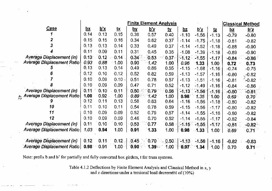
4.1.2 Deflections by Finite Element Analysis and Classical Method in x, y
and z directions under a torsional load de.crement of (10%) 42
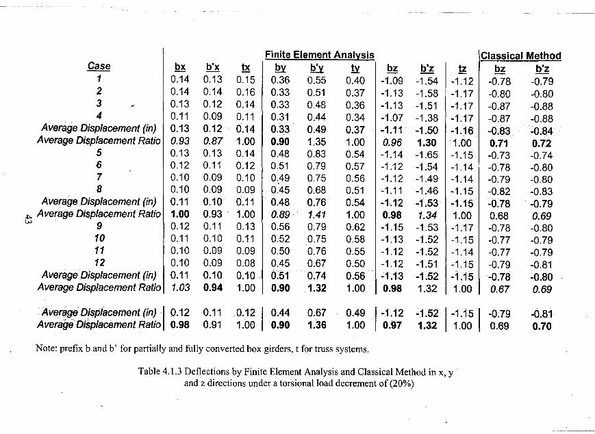
4.1.3 Deflections by Finite Element Analysis and Classical Method in x, y
and z directions under a torsional load decrement of (20%) 43
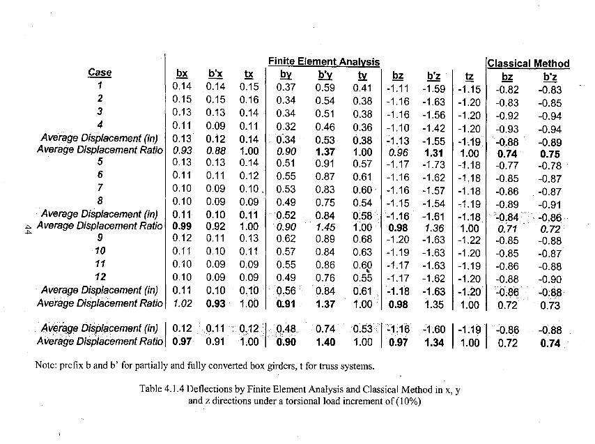
. 4;1.4 Deflections by Finite Element Analysi,s and Classical Method inx, y
and z directions under a torsional load increment of (10%) 44
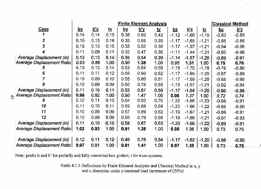
4.1.5 Deflections by Finite Element Analysis and Classical Method in x, y
and z directions under a torsional load increment of(20%) 45
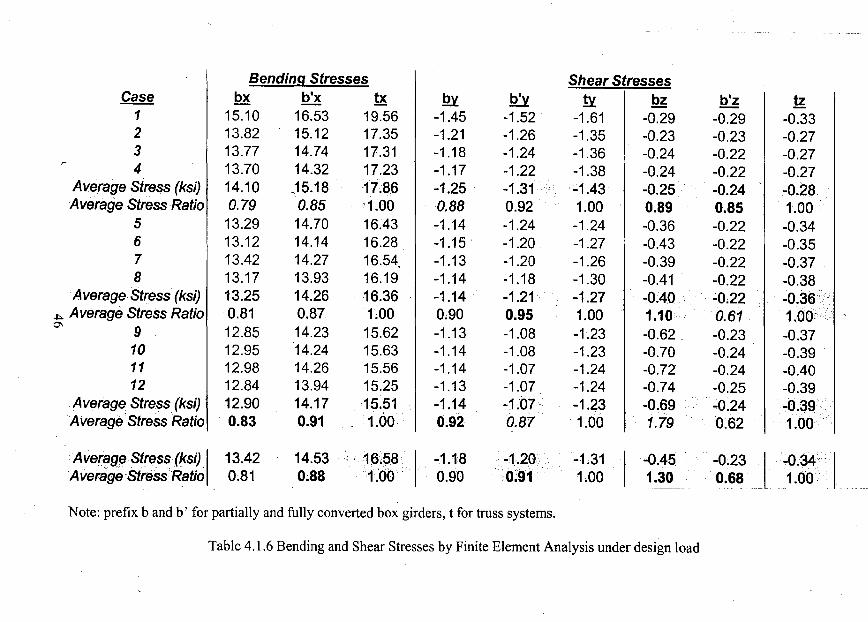
4.1.6 Bending and Shear Stresses by Finite Element Analysis under design load 46
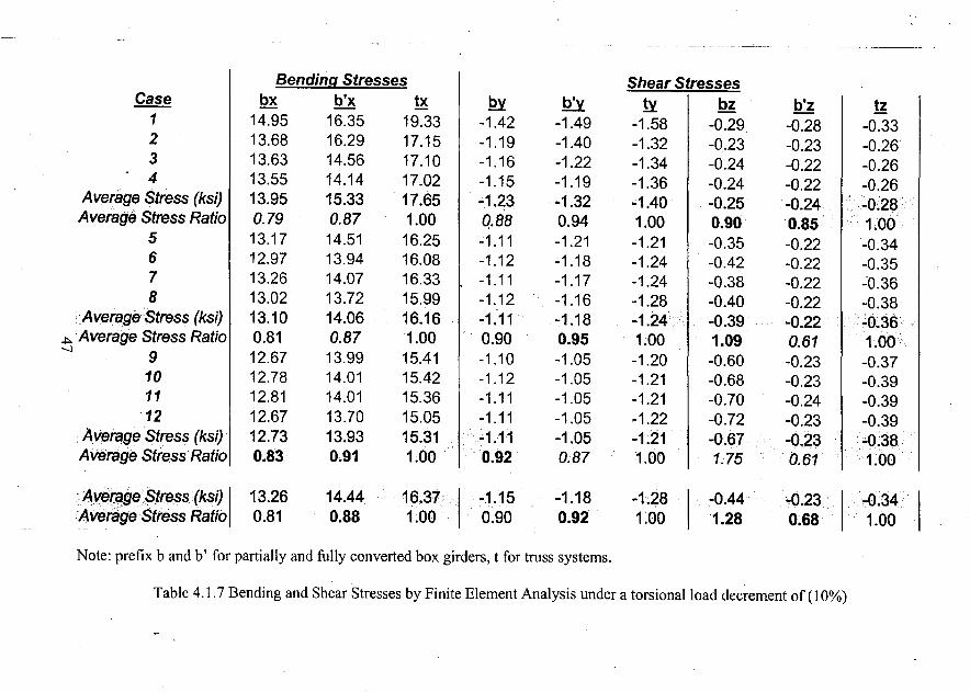
4.1.7 Bending and Shear Stresses by Finite Element Analysis under a torsional
load decrement of(10%) 47
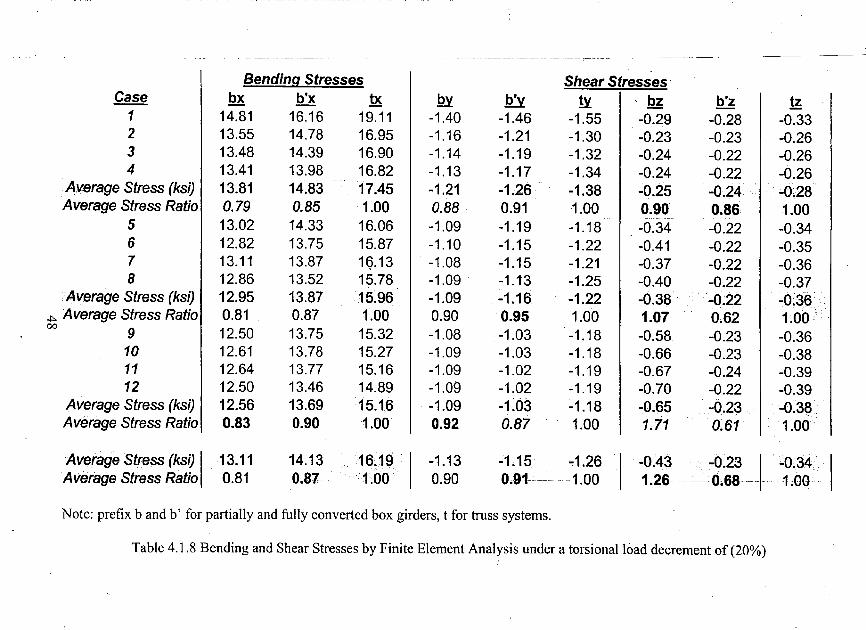
4.1.8 Bending and Shear Stresses by Finite Element Analysis under a torsional
load decrement of (20%) 48
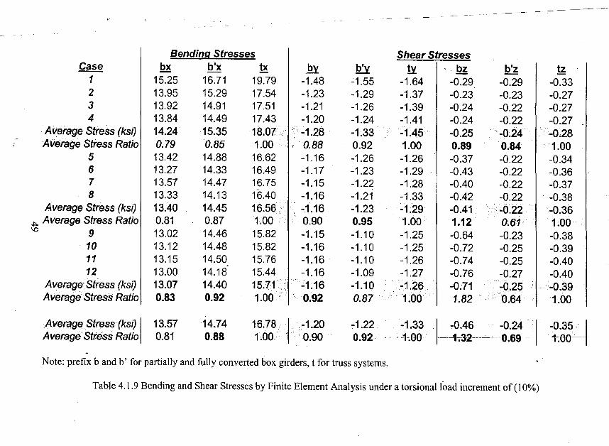
4.1.9 Bending and Shear Stresses by Finite Element Analysis under a torsional
load increment of (1 0%) Q 49
Vll

4.1.10 Bending and Shear Stresses by Finite Element Analysis under a torsional
load increment of (20%) 50
VlIl
LIST OF FIGURES
2.1.1 Conversion of top bracing of an open box section to an equivalent plate
1.1.2 Common simple span deck trusses and lateral bracing systems
. 2.1.3 Common simple span deck trusses and lateral bracing systems·
2.1.4 Common sway (transverse) bracing systems
2.2.1 Conversion of a 3-D Truss system to an equivalentbox girder
3.1.1 General view of rectangular 3-D truss system
3.1.2 General view of equivalent rectangular box girder
3.1.3 General view of trapezoidal 3-D truss system
3.1.4 General view of equivalent trapezoidal box girder
3.1.5 General view of triangular 3-D truss system
3.1.6 General view ofpartially converted equivalent triangular box girder
3.1.7 General view of fully converted equivalent triangular box girder
3.1.8 Truss member sections of Case 1
3.1.9 Truss member sections of Case 2
3.1.10 Truss member sections of Case 3
3.1.11 Truss member sections of Case 4
3.1.12 Truss member sections of Case 5
3.1.13 Truss member sections of Case 6
3.1.14 Truss member sections of Case 7
3.1.15 Truss member sections of Case 8
IX
Page
51
52
53
54
55
56
57
58
59
60
61
62
63---,-- ---
64
65
66
67
68
69
70
3.1.16 Truss member sections of Case 9 71
3.1.17 Truss member sections of Case 10 72
3.1.18 .Truss member sections of Case 11 73
3.1.19 Truss member sections of Case 12 74
3.2.1 3-D views offraI1)es of partially converted rectangular box girder 75
3.2.2 3-D views of frames of fully converted rectangular box girder 76
3.2.3 3-D view of frames of partially converted trapezoidal box girder 77
3.2.4 3-D views of frames of fully converted trapezoidal box girder 78
3.2.5 3-D views of frames of partially converted triangular box 79
3.2.6 3-D views of frames of fully converted triangular box girder 80
3.2.7 Cross-sectional properties of converted box sections for Cases 1 and l' 81
3.2.8 Cross-sectional properties of converted box sections for Cases 2 and 2' 82
3.2.9 Cross-sectional properties of converted box sections for Cases 3 and 3' 83
3.2.10 Cross-sectional properties of converted box sections for Cases 4 and 4' 84
3.2.11 Cross-sectional properties of converted box ~ections for Cases 5 and 5' 85
3.2.12 Cross-sectional properties of converted box sections for Gases 6 and 6' 86
------
3.2.13 Cross-sectional properties of converted box sections for Cases 7 and 7' 87
3.2.14 Cross-sectional properties of converted box sections for Cases 8 and 8' 88
3.2.15 Cross-sectional properties of converted box sections for Cases 9 and 9' 89
3.2.16 Cross-sectional properties of converted box sections for Cases 10 and 10' 90
3.2.17 Cross-sectional properties of converted box sections for Cases 11 and 11' 91
3.2.18 Cross-sectional properties of converted box sections Jor Cases 12 and 12' 92
x
3.3.1 Side, top, bottom and front views of converted rectangular box girder 93
3.3.2 Side, top, bottom and front views of converted trapezoidal box girder 94
3.3.3 Side, top, bottom and front views ofpartially converted triangular box girder 95
3.3.4 Side, top, bottom and front views of fully converted triangular box girder 96
3.3.5 Weight versus Cross:-Section 97
- 3.3.6 Positions of concentrated loads and critical section
4.1.1 Maximum Vertical Deflection .by Finite Element Analysis versus
Torsional Load Change
4.1.2 Maximum Horizontal Deflection in y Direction versus
Torsional Load Change
4; 1.3 Maximum Horizontal Deflection in x Direction versus
Torsional Load Change
4: 1.4 Torsional Constant versus Cross-Section
4.1.5 Maximum Vertical Deflection Calculated by Finite Element Analysis'
versus Cross-Section
4.1.6 Maximum Horizontal Deflection in y Direction versus Cross-Section
---- -~-- - ~~~-
4.1.7 Maximum HoriZontal DefleCtion in x Direction versus Cross-Section
4.1.8 Maximum Vertical Deflection by Finite Element Analysis versus Torsional
98
99
100
101
102
103
104
105
Load Change, Twelve Fully and Partially Converted Box Girders 106
4.1.9 Maximum Vertical Deflection by Finite Element Analysis versus
Torsional Load Change, Twelve Fully and Partially Converted Box
Girders versus Trusses
Xl
107
4.1.10 Maximum Horizontal Deflection in y Direction versus Torsional Load Change
Twelve Fully and Partially Converted Box Girders versus Trusses 108. - ..
4.1.11 Maximum Horizontal Deflection in x Direction versus Torsional Load Change
Twelve Fully and Partially Converted Box Girders versus Trusses 109
4.2.1 Maximum Vertical Deflection by Classical Mechanics Method versus
Torsional Load Change 110
4.2.2 Maximum Vertical Deflection by Classical Method versus Cross-Section 111
4.2.3 Maximum Vertical Deflection by Classical Mechanics Method versus
Torsional Load Change, Twelve Fully and Partially Converted Box
Girders versus Trusses 112
4.2.4 Maximum Vertical Deflection of Partially Converted Box versus
Torsional Load Cha~ge 113
4.2.5 Maximum Vertical Deflection versus Torsional Load Change, Twelve
Partially Converted Box Girders versus Trusses 114
Xll
ABSTRACT
Designing a three dimensional (3-D) truss system as a combination of two
. dimensional plane trusses ignores the torsional character of the system and often
results in larger than necessary truss member sizes. In this study, the possibility and
accurateness of conversion of 3-D truss systems into equivalent closed box sections
for the examination of torsional behavior of 3-D truss systems were investigated.
Twelve 3-D steel truss models and twelve equivalent steel box girder models
were studied under five different loading conditions. The equivalent box girder
models were obtained by the analytical conversion of each side (2-D trusses) of a 3-D
truss structure to equivalent plates by· strain energy method. Two types of
conversions, named as partial and full conversion, were investigated.
Finite element analysis and the classical mechanics method were tools for the
analysis. Finite element analysis was used to obtain the deflection values of the truss
systems and of the converted box girders: Results of analyzing the equivalent box
~Jrders by the classical method to investigate the applicability of the conversion
. ~ethod provided estimation of deflections ofthe 3-D truss systems.
1
1. INTRODUCTION
Increased competition leads to innovative ideas and it applies to structural
engineering. Innovative structural designs which meet the functional requirements of
performance, reduce the time and cost of construction, minimize the maintenance and
are aesthetically pleasing usually stand out in competition. Although, satisfying the
aesthetics criteria seems to be the least important factor among the others, it could be
the most significant in winning the contract.
For bridges and elevated guideway structures, deck and girder systems and
box girders are widely being used as the main structur~l units. Each type has its own
advantages. On the other hand, steel truss systems are not widely used although they,
possess all the structural advantages of the other types and are often considered
aesthetically desirable. Likely reasons include possible higher cost of fabrication and
the common concept that trusses are two dimensional (2-D) structural members.
In current practice, steel bridge truss systems are designed as 2-D members
without taking into account the torsional capacity of actual three dimensional (3-D)
structure. This condition results in over designed structures with larger than necessary.trus.s members. If the concept of equivalent plate of open steel box girders can be
truss systems can be a better alternative to other types.
Kollbrunner - Basler (1969) and Roik - Carl - Lindner (1972) conducted.
analytical work to convert open steel box sections with bracing to closed steel box
sections by replacing the bracing with a fictitious equivalent wall element of constant
2
thickness (teq) through out the length of the box. McDonald (1973) and Heins, Snyder
& Blank (1974) conducted experimental studies on open steel box sections.
Conceptually, each side of a 3-D truss' structure of prismatic shape can be
converted to an equivalent plate, forming an equivalent box girder. In this study, the
possibility and accurateness of the utilization of this concept of a fictitious box girder
were investigated.
The specific objectives of this study were: 1) to develop a procedure of
converting a prismatic bridge truss system to an equivalent, fictitious box girder for
evaluation of behavior; 2) to examine the adequacy of the equivalent box girder when
the truss system is subject to torsional loads; and 3) to compare the behavior of
various shape of truss systems for a sample bridge superstructure.
3
2. CONCEPT OF EQUIVALENT BOX GIRDER.
,
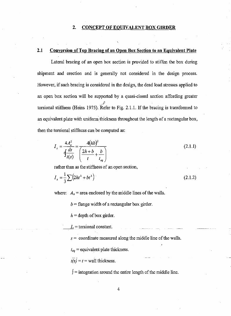
2.1 Conversion of Top Bracing of an Open Box Section to an Equivalent Plate
Lateral bracing of an open box section is provided to stiffen the box during
shipment and erection and is generally not considered in the design process.
However, if such bracing is considered in the design, the dead load stresses applied to
an open box section will be supported by a quasi-closed section affording greater
.Jltorsional stiffness (Heins 1975). 'Refer to Fig. 2.1.1. If the bracing is transformed to
an equivalent plate with uniformthickness throughout the length of a rectangular box,
then the torsional stiffness can be computed as:
I = 4A~ = 4(hbY
x ds ( )1t(s) 2h+b +~
t teq
rather than as the stiffness of an open section,
where: Ao = area enclosed by the middle lines of the walls.
b = flange width of a rectangular box girder.
h = depth ofbox girder.
-----.Ix = JorsiQlJa:l constant.
s = coordinate measured along the middle line ofthe walls.
teq = equivalent plate thickness.
t(s) = t = wall thickness.
J= integration around the entire length of the middle line.
4
(2.1.1)
(2.1.2)
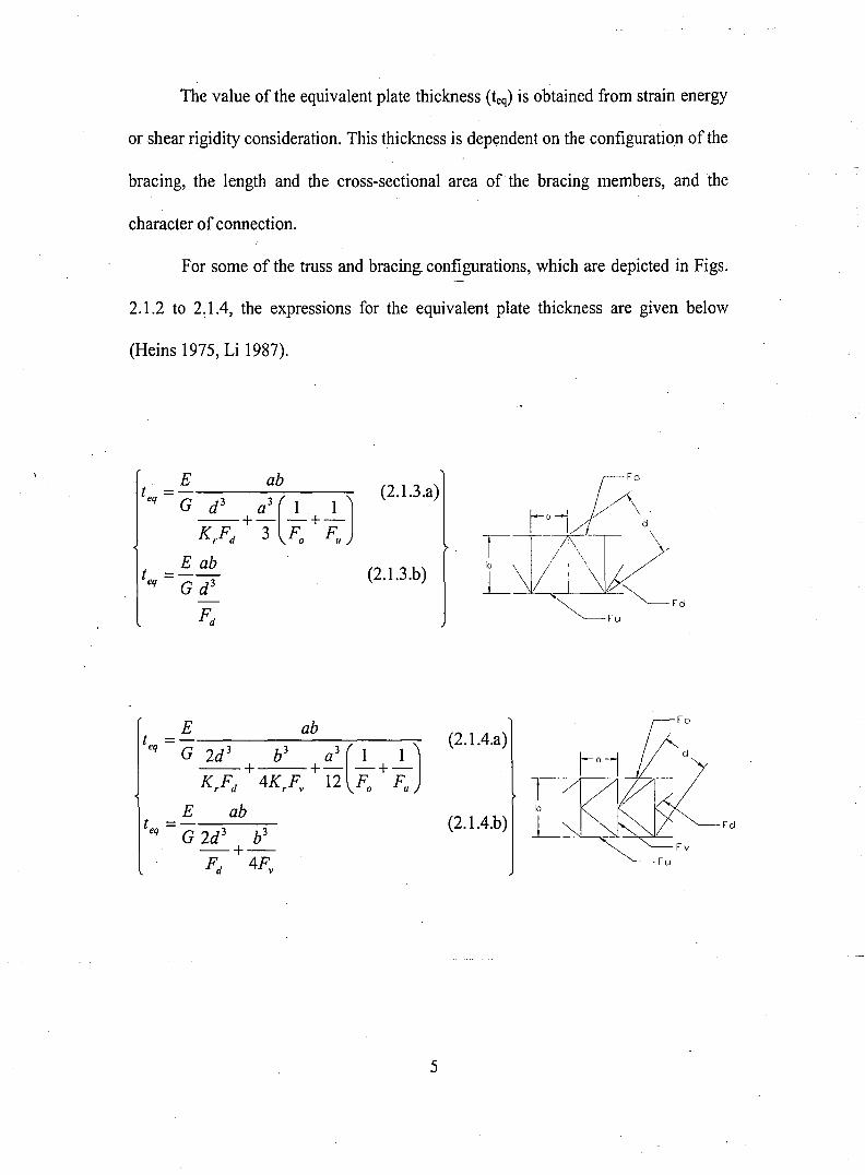
The value ofthe equivalent plate thickness (teq) is obtained from strain energy
or shear rigidity consideration. This thickness is dependent on the configuration of the
bracing, the length and the cross-sectional area of the bracing members, and the
character of connection.
For some of the truss and bracing configurations, which are depicted in Figs.
2.1.2 to 2: lA, the expressions for the equivalent plate thickness are given below
(Heins 1975, Li 1987).
E abt =- ( J (2.1.3.a)
eq G d 3 a3 1 1
KrFd+3 Fo+Fu
E abt =-- (2.1J.b)
eq Gd3
Fd
5
(2. 1A.a)
Ib
(2.1A.b) L -O>..--....---'"-~'--
tutV
td
(2.1.5.a)
(2.1.5.b)
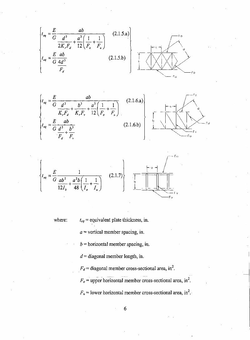
E 1t = - (J (2.1.7)eq G ab 2 a2b 1 1
121b + 48 10
+1u
where: teq = equivalent plate thickness, in.
a =vertical member spacing, in.
b =horizontal member spacing, in.
d = diagonal member length, in.
Fd = diagonal member cross-sectional area, in2•
Fa = upper horizontal member cross-sectional area, in2•
Fu =lower horizontal member cross-sectional area, in2.,
6
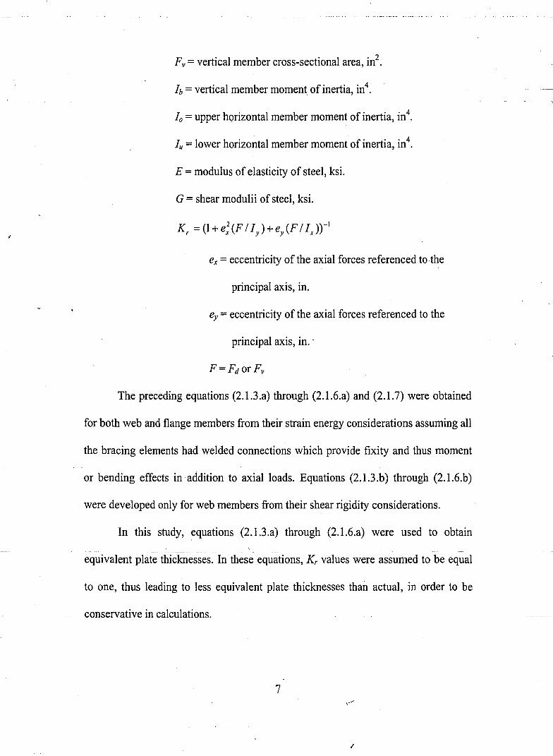
Fv = vertical member cross-sectional area, in2•
1b = vertical member moment of inertia, in4•
10 = upper horizontal member moment of inertia, in4.
1u =lower horizontal member moment of inertia, in4•
E = modulus of elasticity of steel, ksi.
G = shear modulii of steel, ksi.
ex =eccentricity of the axial forces referenced to the
principal axis, in.
ey =eccentricity of the axial forces referenced to the
principal axis, in..
The preceding equations (2.1.3.a) through (2.1.6.a) and (2.1.7) were obtained
for both web and flange members from their strain energy considerations assuming all
the bracing elements had welded connections which provide fixity and thus moment
or bending effects in addition to axial loads. Equations (2.1.3.b) through (2.1.6.b)
were developed only for web members from their shear rigidity considerations.
In this study, equations (2.1.3.a) through (2.1.6.a) were used to obtain
-- - ---
equivalent plate thicknesses. In these equations, Kr values were assumed to be equal
to one, thus leading to less equivalent plate thicknesses than actual, in order to be
.conservativeincalculations.
7,-/
I
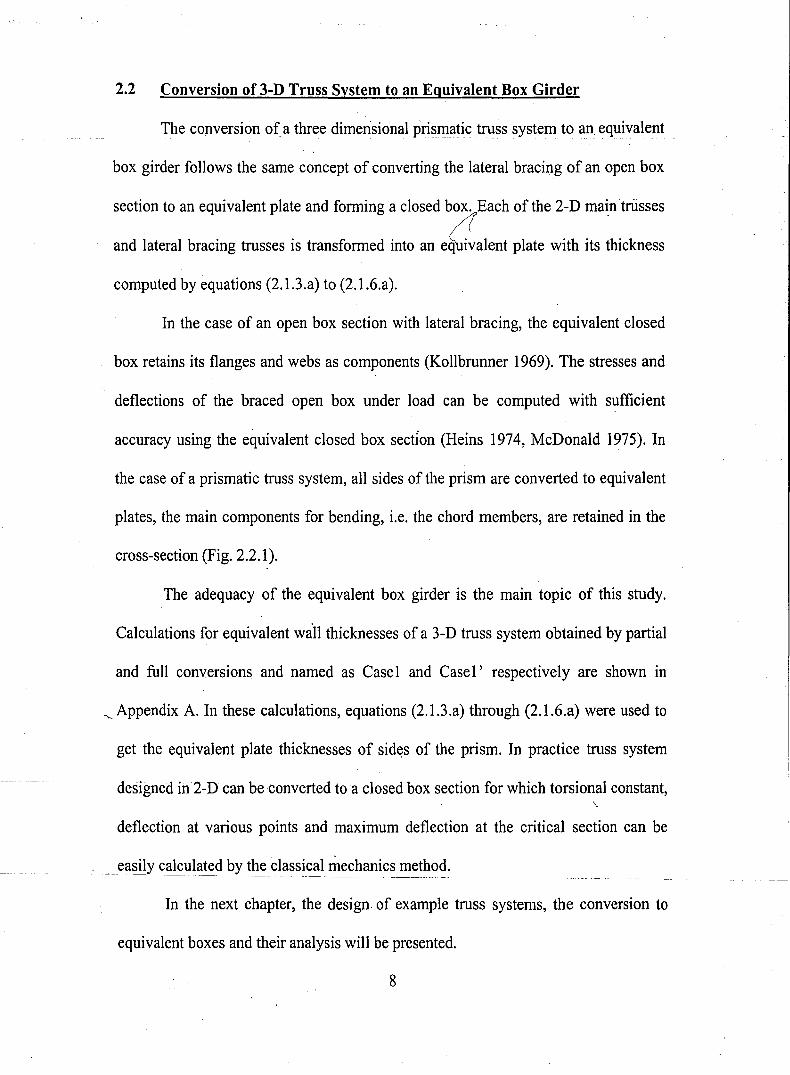
2.2 Conversion of 3-D Truss System to an Equivalent Box Girder
The conversion of. a three dimensional pri~~~tic truss system to an equivalent
box girder follows the same concept of converting the lateral bracing of an open box
section to an equivalent plate and forming a closed box. Each of the 2-D main trusses
and lateral bracing trusses is transformed into an eaalent plate with its thickness
computed by equations (2.IJ.a) to (2.1.6.a).
In the case of an open box section with lateral bracing, the equivalent closed
box retains its flanges and webs as components (Kollbrunner 1969). The stresses and
deflections of the braced open box under load can be computed with sufficient
accuracy using the equivalent closed box sectIon (Heins 1974, McDonald 1975). In
the case of a prismatic truss system, all sides of the prism are converted to equivalent
plates, the main components for bending, i.e. the chord members, are retained in the
cross-section (Fig. 2.2.1).
The adequacy of the equivalent box girder is the main topic of this study.
Calculations for equivalent wan thicknesses of a 3-D truss system obtained by partial
and full conversions and named as Case1 and Case1' respectively are shown in
'- Appendix A. In these calculations, equations (2.1.3.a) through (2.1.6.a) were used to
get the equivalent plate thicknesses of sid~s of the prism. In practice truss system
designed in2-D cart be converted toa closed box section for which torsional constant,\
deflection at various points and maximum deflection at the critical section can be
. easily calculated bl th~ classical mechanics method.
In the next chapter, the design of example truss systems, the conversion to
equivalent boxes and their analysis will be presented.
8
3. ANALYSIS OF MODELS
3.1 Description of Models
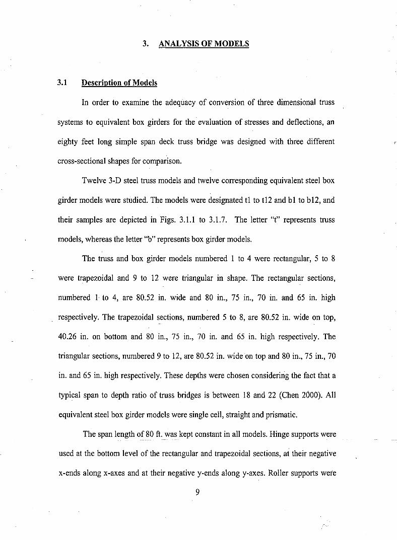
In order to examine the adequacy of conversion of three dimensional truss
systems to equivalent box girders for the evaluation of stresses and deflections, an
eighty feet long simple span deck truss bridge was designed with three different
cross-sectional shapes for comparison.
Twelve 3-D steel truss models and twelve corresponding equivalent steel box
girder models were studied. The models were designated tl to tI2 and bl to b12, and
their samples are depicted in Figs. 3.1.1 to 3.1.7. The letter "t" represents truss
models, whereas the letter "b" represents box girder models.
The truss and box girder models numbered 1 to 4 were rectangular, 5 to 8
were trapezoidal and 9 to 12 were triangular in shape. The rectangular sections,
numbered 1 to 4, are 80.52 in. wide and 80 in., 75 in., 70 in. and 65 in. high
respectively. The trapezoidal seCtions, numbered 5 to 8, are 80.52 in. wide on top,
40.26 in. on bottom and 80 in., 75 in., 70 in. and 65 in. high respectively. The
triangular sections, numbered 9 to 12, are 80.52 in. wide on top and 80 in., 75 in., 70
in. and 65 in. high respectively. These depths were chosen considering the fact that a
typical span to depth ratio of truss bridges is between 18 and 22 (Chen 2000). All
equivalent steel box girder models were single cell, straight and prismatic.
The span length of 80 ft. was kept c~E_s!aEtJI1_a.IL~0~el~. Hinge supports were
used at the bottom level of the rectangular and trapezoidal sections, at their negative
x-ends along x-axes and at their negative y-ends along y-axes. Roller supports were
9
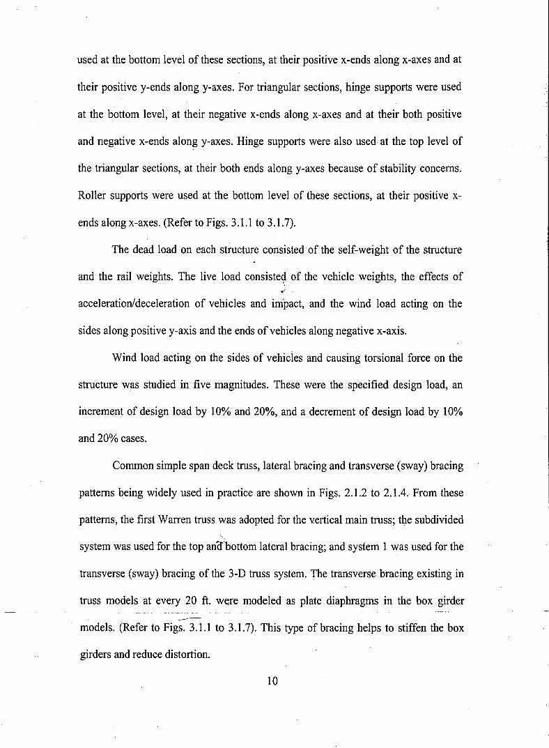
used at the bottom level of these sections, at their positive x-ends along x-axes and at
their positive y-ends along y-axes. For triangular sections, hinge supports were used
at the bottom level, at their negative x-ends along x-axes and at their both positive
and negative x-ends along y-axes. Hinge supports were also used· at the top level of
the triangular sections, at their both ends along y-axes because of stability concerns.
Roller supports were used at the bottom level of these sections,. at their positive x-
ends along x-axes. (Refer to Figs. 3.1.1 to 3.1.7).
The dead load on each structure consisted' of the self-weight of the structure
and the rail weights. The live load consiste<;l of the vehicle weights, the effects of
acceleration/deceleration of vehicles and impact, and the wind load acting on the
sides along positive y-axis and the ends of vehicles along negative x-axis.
Wind load acting on the sides of vehicies and causing torsional force on the
structure was studied in five magnitudes. These were the specified design load, an
increment of design load by 10% and 20%, and a decrement of design load by 10%
and 20% cases.
Common simple span deck truss, lateral bracing and transverse (sway) bracing
patterns being widely used in practice are shown in Figs. 2.1.2 to 2.1.4. From these
patterns, the first Warren truss was adopted for the v.ertical main truss; the subdivided
system was used for the top an,(f'bottom lateral bracing; and system 1 was used for the
transverse (sway) bracing of the 3-D truss system. The transverse bracing existing in
truss models at every 20 ft. we.re modeled as plate diaphragms in the box girder
models. (Refer to Figs. 3.1.1 to 3.1.7). This type of bracing helps to stiffen the box
girders and reduce distortion.
10
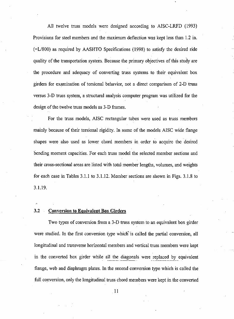
All twelve truss models were designed according to AISC-LRFD (1993)
Provisions for steel members and the maximum deflection was kept less than 1.2 in.
(=Ll800) as required by AASHTO Specifications (1998) to satisfy the desired ride
quality of the transportation system. Because the primary objectives of this study are
the procedure and adequacy of converting truss systems to their equivalent box
girders for examination of torsional behavior, not a direct comparison of 2-D truss
versus 3-D truss system, a structural analysis computer program was utilized for the
design of the twelve truss models as 3-D frames.
For the truss models, AISC rectangular tubes were used as truss members
mainly because of their torsional rigidity. In some of the models AISC wide flange
shapes were also used as lower chord members in order to acquire the desired
bending moment capacities. For each truss model the selected member sections and
their cross-sectional areas are listed with total member lengths, volumes, and weights
for each case in Tables 3.1.1 to 3.1.12. Member sections are shown in Figs. 3.1.8 to
3.1.19.
3.2 Conversion to Equivalent Box Girders
Two types of conversion from a 3-D truss system to an equivalent box girder
were studied. In the first conversion type which""' is called the partial conversion, all
longitudinal and transverse horizontal members and vertical truss members were kept
in the converted box girder while all the diagonals were replaced by equivalent
flange, web and diaphragm plates. In the second conversion type which is called the
full conversion, only the longitudinal truss chord members were kept in the converted
11
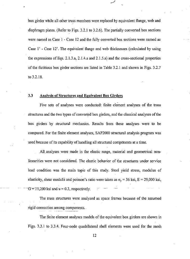
box girder while all other tru?s members we~e replaced by equivalent flange, web and
diaphragm plates. (Refer to Figs. 3.2.1 to 3.2.6). The partially converted box sections
.were named as Case 1 - Case 12 and the fully converted box sections were named as
Case l' - Case 12'. The equivalent flange and web thicknesses (calculated by using
the expressions of Eqs. 2.1.3.a, 2.1.4.a and 2.1.5.a) and the cross-sectional properties
of the fictitious box girder sections are listed in Table 3.2.1 and shown in Figs. 3.2.7
to 3.2.18.
3.3 Analysis of Structures and Equivalent Box Girders
Five sets of analyses were conducted: finite element analyses of the truss
structures and the two types of converted box girders, and the classical analyses of the
box girders by structural mechanics. Results from these analyses were to be
compared. For the finite element analyses, SAP2000 structural analysis program was
used because of its capability ofhandling all structural components at a time.
AI~, analyses were made in the elastic range, material and geometrical non-
linearities were not considered. The elastic behavior of the structures under service
load condition was the main topic of this study. Steel yield stress, modulus of
elasticity, shear modulii and poisson's ratio were taken as cry = 36 ksi, E = 29,000 ksi,
G=~ll;200~ksi and u = 0.3-;-respectively.
The truss structures were analyzed as space frames because of the assumed
rigid connection among components.
The finite element analyses models of the equivalent box girders are shown in
Figs. 3.3.1 to 3.3.4. Four-node quadrilateral shell elements were used for the mesh
12
formation of equivalent flange and web plates. Both four-node quadrilateral and .
three-node triangular shell elements were used for the mesh formation of the
equivalent diaphragm plates of the converted box girders. Shell elementswere· chosen
because they show a combination of membrane and plate behavior, in other words
they can support in-plane and transverse forces and normal (drilIing) and bending
moments. Membrane and bending thicknesses of these elements were taken to be the
same. The maximum aspect ratio of the four node quadrilateral shell elements used
was 3 for the 4 in. by 12 in. element, in all models. The maximum aspect ratio of the
three-node triangular shell elements used was 3.97 for the 1.0065 in. by 4 in. element,
in trapezoidal models (Fig. 3.3.2) and 1.99 for the 2.013 in. by 4 in. element, in
triangular models (Fig. 3.3.4). These values were chosen by trying different element
sizes for a suitable finite element mesh and keeping in mind that the best results were
obtained for aspect ratios near unity, or at least less than four (SAP2000 1997).
Since the equivalent box girders are composed of fictitious flanges and webs,
the self-weight of these box girders are less than those of corresponding truss
systems. Comparison of the truss systems' weights with the partially and fully
converted imaginary box girders' weights shows that the truss systems are heavier
than the partially converted boxes by 25% and the fully converted boxes by 26% in
average. Refer to Tables 3.1.1 to 3.1.12, 3.2.1 and Appendix B. Figure 3.3.5 shows
the weight difference of all model cases. To account for this condition in finite
element analysis, the self-weights of the equivalent flange and web plates of the
converted box girders were ignored while the self-weights of the truss members that
were converted to equivalent plates were transferred to the bottom frame members.
13
These weights were transferred as uniform vertical loads along the length of the
boxes. In the partially converted box models, transverse frame members (along y-
axes) were not assigned any loads because their relative short length comparing to the
longitudinal main members; one-way action of weight distribution was assumed.
Load transfer values for the partial and full conversions of all cases can be found in
Tables 3.1.1 to 3.1.12.
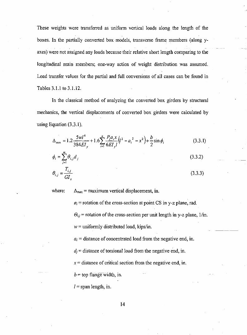
In the classical method of analyzing the converted box girders by structural
mechanics, the vertical displacements of converted box girders were calculated by
using Equation (3.3.1).
m
¢; =Le;.jdjj=l
T, .e..=--!:.LI,J GI
x
(3.3.1)
(3.3.2)
(3.3.3)
where: ~max = maximum vertical displacement, in.
@j = rotation of the cross-section at point CS in y-z plane, rad.
eij = rotation of the cross-section per unit length in y-z plane, l/in.
w=uniformly distributed load, kips/in.
ai = distance of concentrated load from the negative end, in.
dj = distance of torsional load from the negative end, in.
x = distance of critical section from the negative end, in.
b = top flange-width, in.
I =span length, in.
14
Ix = torsional constant, in4•
.Jy = moment of inertia of the cross-section, in4•
E = modulus of elasticity of steel, ksi.
G = shear modulii of steel, ksi.
Pi = concentrated load, kips.
TiJ = torsional load, kips-in.
In computationsn and m refer to number of concentrated load and torque7!
.conditions respectively. For this study, where the vehicle of a guideway was used, the
concentrated load (Pi) and torsional load (TiJ) calculations can be found in
Appendices C and D. A two-car vehicle was assumed to move on the 80 ft. long
structure frorii--tlierigliCto tlieleftofFig.-3.3.6:--The loads PI and Pz stand for the
concentrated loads applied on the structure by the tires of the front car and P3 and P4,
by the tires of the rear car. By the classical mechanics method, the maximum vertical
displacemen.t of a converted box girder was calculated at point CS under the
concentrated load P3, 566.28 in. from the left end and at the tip of the top flange (b12
= 80.52/2 = 40.26 in.).
15
4. COMPARISON OF RESULTS OF ANALYSES
4.1 Evaluation of Partial and Full Conversion Methods
The computed deflections of the converted box girders are compared for the
evaluation of the conversion methods. An eighty inch deep truss system with a
rectangular cross section is used as an example.
Figure 4.1.1 shows the computed maximum vertical deflection of the truss
system and the partially and fully converted box girders. Plotted in the figure are the
results of five different magnitudes of torsional loads: the code specified and 10% and
20% increase and decrease. The vertical deflections of the partially converted box
girder agree quite well with those of the truss system. It appears that retaining the
verticals and the horizontal bracing members at the cross diaphragms, the converted
box girder provides a better representation of the truss system. Similar results are
I
obtained when the lateral horizontal deflections (in y-direction) are examined (Fig.
4.1.2). In the direction of the bridge (x-direction), the partially and fully converted
boxes have about the same deflections, which agree fairly well with those of the truss
system (Fig. 4.1.3).
---~--~~~
For all twelve cases of different bridge cross-sections, the same qualitative
results are obtained. The partially converted box girder models have higher torsional
rigidity (Fig. 4.1.4) and their vertical and lateral horizontal deflections under code-
specified torsion agree better with those computed from the truss systems (Figs. 4.1.5
and 4.1.6). Again, in the direction of the vehicle movement, both partially and fully
16
converted boxes have computed deflections in fair agreement with those of the truss
systems.
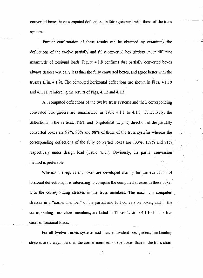
Further confirmation of these results can be obtained by examining the
deflections of the twelve partially and fully converted box girders under different
magnitude of torsional loads. Figure 4.1.8 confirms that partially converted boxes
always deflect vertically less than the fully converted boxes, and agree better with the
trusses (Fig. 4.1.9). The computed horizontal deflections are shown in Figs. 4.1.10
and 4.1.11, reinforcing the results ofFigs. 4.1.2 and 4.1.3.
All computed deflections of the twelve truss systems and their corresponding
converted box girders are summarized in Table 4.1.1 to 4.1.5. Collectively, the
deflections in the vertical, lateral and longitudinal (z, y, x) direction of the partially
converted boxes are 97%, 90% and 98% of those of the truss systems whereas the
corresponding deflections of the fully converted boxes are 133%, 139% and 91%
respectively under design load (Table 4.1.1). Obviously, the partial converSIOn
. method is preferable.
Whereas the equivalent boxes are developed mainly for the evaluation of
torsional deflections, it is interesting to compare the computed stresses in these boxes
-
with the corresponding stresses in the truss members. The maximum computed
stresses in a "corner member" of the partial and full conversion boxes, and in the
corresponding truss chord members, are listed in Tables 4.1.6 to 4.1.10 for the five
cases of torsional loads.
For all twelve trusses systems and their equivalent box girders, the bending
stresses are always lower in the corner members of the boxes than in the truss chord
17
members. For example, for the 80 in. deep rectangular cross section under design load
(Case 1 in Table 4.1.6) the bending stress in the truss chord is 19.56 ksi while those in
the partial and full conversion boxes are 15.10 ksi and 16.53 ksi, respectively. The
partial conversion box, being better than the full conversion box in examination of
deflection, is less accurate in computed stresses when the stresses are compared to
those in the truss members. For the four rectangular truss systems under design loads
(Cases 1 to 4 in Table 4.1.6) the" average ratio of bending, horizontal shear and
vertical shear stresses in the corner member of the partial and full conversion boxes
are 0.79, 0.85; 0.88,0.92 and 0.89, 0.85, respectively.
It must be recognized that the equivalent box girders are quite different from
the trusses in distribution of forces and stresses among their component members.
The computed stresses in the corner members served as an indication that the
converted box girders are reasonable and adequate tools for the examination of
deflections. Based on the comparison of deflections, the partial conversion box girder
model is recommended for the procedure.
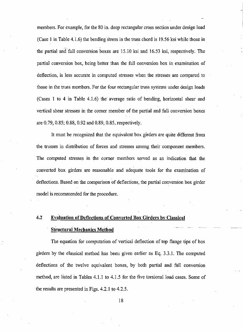
4.2 Evaluation of Deflections of Converted Box Girders by Classical
Structural Mechanics Method
The equation for computation of vertical deflection of top flange tips of box
girders by the classical method has beell given earlier as Eq. 3.3.1. The computed
deflections of the twelve equivalent boxes, by both partial and full conversion
method, are listed in Tables 4.1.1 to 4.1.5 for the five torsional load cases. Some of
the results are presented in Figs. 4.2.1 to 4.2.5.
18
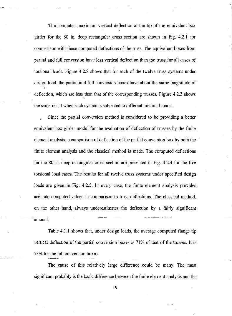
The computed maximum vertical deflection at the'ltip of the equivalent box
girder for the 80 in. deep rectangular cross section are· shown in Fig. 4.2.1 for
comparison with those computed deflections of the truss. The equivalent boxes from
partial and full conversion have less vertical deflection than the truss for all cases of
torsional loads. Figure 4.2.2 shows that for each of the twelve truss systems under
design load, the partial and full conversion boxes have about the same magnitude of
deflection, which are less than that of the corresponding trusses. Figure 4.2.3 shows
the same result when each system is subjected to different torsional loads.
Since the partial conversion method is considered to be providing a better
equivalent box girder model for the evaluation of deflection of trusses by the finite
element analysis, a comparison of deflection of the partial conversion box by both the
finite element analysis and the classical method is made. The computed deflections
for the 80 in. deep rectangular cross section are presented in Fig. 4.2.4 for the five
torsional load cases. The results for all twelve truss systems under specified design
loads are given in Fig. 4.2.5. In every case, the finite element analysis provi,des
accurate computed values in comparison to truss deflections. The classical method,
on the other hand, always underestimates the deflection by a fairly significant
amount.
Table 4.1.1 shows that, under design loads, the average computed flange tip
vertical deflection of the partial conversion boxes is 71 % of that of the trusses. It is
73% for the full conversion boxes.
The cause of this relatively large difference could be many. The most
significant probably is the basic difference between the finite elementanalysis and the
19
classical method of computing the deflection. While the finite element analysis
considers__allJo_caLdeflections_and_defonnation ofthe-components-andthe-structure,---
including that of the local deflection of the fictitious flange and web plates of the
equivalent boxes, the classical structural mechanics procedure of torsion and bending
~nalyses adopted for the study assumes that the box girders retain their cross-sectional
shapes.
It appears that, by adding a multiplication factor, the deflection of the three
dimensional truss systems can be estimated by using the fictitious partial conversion
equivalent box girders. The multiplication factor for the twelve case would be
(110.71), or about 1.4.
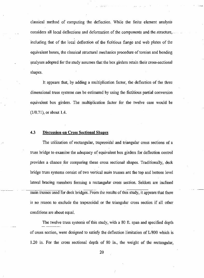
4.3 Discussion on Cross Sectional Shapes
The utilization of rectangular, trapezoidal and triangular cross sections of a
truss bridge to examine the adequacy of equivalent box girders for deflection control
provides a chance. for comparing these cross sectional shapes. Traditionally, deck
bridge truss systems consist of two vertical main trusses ant the top and bottom level
lateral bracing members forming a rectangular cross section. Seldom are inclined
main trusses used for deck bridges. From the results of this study, it appears that there
is no reason to exclude the trapezoidal or the triangular cross section if all other
conditions are about equal.
The twelve truss systems of this study, with a 80 ft. span and specified depth
of cross section, were designed to satisfy the deflection limitation of Ll800 which is
1.20 in. For the cross sectional depth of 80 in., the weight of the rectangular,
20
trapezoidal and triangular cross sections are about the same with the chosen
--- componenLmember-sizes.Jhe-partiaLcoTI-\'ersion equiv:alent box~.girder-sections ,all
have about the same magnitude of vertical deflection, being 96%, 98% and 98% by
the finite element analysis for the rectangular, trapezoidal and triangular cross-
section, respectively, when compared with those of the corresponding trusses (Table
4.1.1). The corresponding values are 73%, 70% and 70% when the classical method
is used for deflection calculation. All these indicate that either the trapezoidal or the
triangular shape can be utilized if desired.
Examination of the bending stresses in the chord members of the truss systems
also leads to the same conclusion stated above. The bending stresses in the chord
members of the rectangalar, trapezoidal and triangular truss systems are 17.86 ksi.,
16.86 ksi. and 15.51 ksi. respectively (Table 4.1.6). The ratio of computed partial
conversion box girder comer members are 79%, 81 % and 83%. All are practically
equal.
. Whether a trapezoidal cross-section is more practical or a triangular cross·
.section is more pleasing aesthetically, is to be judge by the circumstances of the
bridge. The results of this study suggest that both can be utilized, as does the
rectangular cross sectional shape.
21
5. SUMMARY, CONCLUSION AND RECOMMENDATIONS
5.1 Summary and Conclusions
The primary purpose of this study is to examine the possibility and accuracy
of using an equivalent box girder for evaluating deflections of truss bridges, which
have the trusses designed as two dimensional members. The work and results are
summarized below.
(1) Twelve deck truss systems of 80 ft. span length and with different cross
sectional depth and shapes were designed by limitation ofdeflection (U800)
(2) These truss systems were converted to' equivalent box girders by using the
equivalent thickness concept, which was developed for lateral bracing systems
of open box section. Each of the two dimensional trusses and the lateral
bracing between them was converted to an equivalent plate. (The equations
for conversion are presented in Section 2.1 and Partial and Full Conversion
Examples are presented in Appendix A).
(3) Two methods of conversion were examined. The partial conversion model
retains in the equivalent box section the verticals of the main trusses and the
transverse horizontal members of the lateral bracing system, as well as the
chord members of the main trusses. In the full conversion method, only the",.
chord members of the main trusses are retained in the equivalent box girder.
(4) The deflections of the truss systems and of the converted equivalent box
girders were' computed by a finite element analysis procedure. Because the
self-weights of the equivalent boxes are less than those of the corresponding
22
truss systems, the weight of the truss system must be. applied to the boxes.
Results indicate that partially converted boxes are better representation of the·
truss systems with respect to deflection.
(5) The deflections at points of the equivalent box girders were computed using
the classical method of structural mechanics. (The equations for calculation
are presented as Eq. (3.3.1) (in Section 3.3) and Eq. (d2) in Appendix D).
(6) Results of defl,ections computed from partially converted equivalent boxes by
the classical method are lower than those corresponding deflections of truss
systems, computed by the finite element analysis. The ratio is about 0.7/1.0
(or 1.0/1.4). A multiplication factor of 1.4 is suggested.
(7) From the results of corresponding deflections, stresses and structure weight of
rectangular, trapezoidal and triangular cross-sections, all three shapes can be
adopted adequately for deck truss bridges.
5.2 Recommendations
A more exhaustive examination of the deflections of truss systems and their
equivalent box girders is recommended. Various span lengths, cross sectional shapes
andaifferent loads need to be considered. The adequacy of the multiplication factor'J.
needs to be investigated.
23
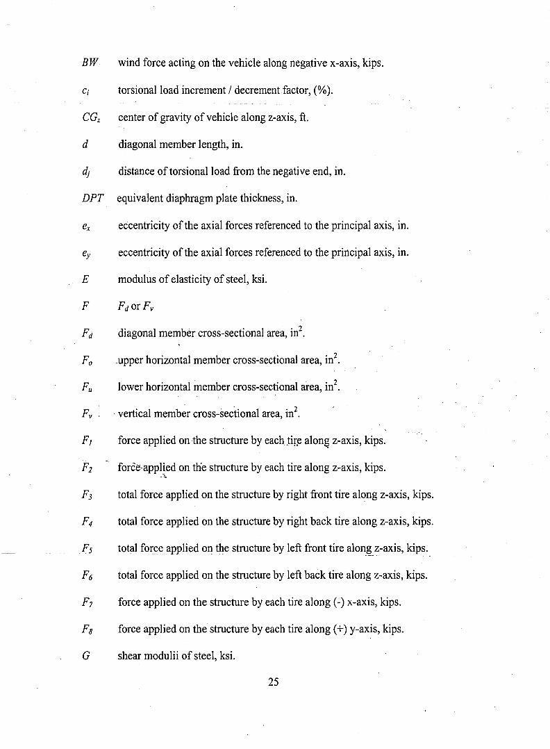
NOMENCLATURE
a vertical member spacing, in.
Ao area enclosed by the middle lines of the walls.
AD acceleration / Deceleration force applied on the structure, kips.
Ax cross-sectional area of the virtual box girder, in2.
Ay shear area of the virtual box girder along y-axis, in2•
Az shear area ofthe virtual box girder alongz-axis, in2.
b flange width of a rectangular box girder.
b horizontal member spacing, in.
b top flange width, in.
bx partially converted box girder deflection in x direction.
by partially converted box girder deflection in y direction. .
bz . partially converted box girder deflection in z direction.
b 'x fully converted box girder deflection in x direction.
by fully converted box girder deflection in y direction.
b 'z fully converted box girder deflection in z direction.
25
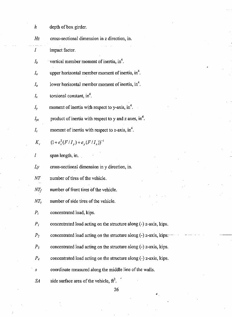
h depth ofbox girder.
Hz cross-sectional dimension in z direction, in.
I impact factor.
Ib vertical member moment of inertia, in4•
10 upper horizontal member momerit of inertia, in4•
Iu lower horizontal member moment of inertia, in4•
Ix torsional constant, in4.
Iy moment of inertia with respect to y-axis, in4•
Iyz product of inertia with respect to y and z axes, in4•
Iz moment of inertia with respect to z-axis, in4.
I span length, in.
Ly cross-sectional dimension in y direction, in.
NT J?umber of tires of the vehicle.
NT! number of front tires of the vehicle.
NTs number of side tires of the vehicle.
Pi concentrated load, kips.
PI concentrated load acting on the structure along (-) z-axis, kips.
P2 concentrated load acting on the structure along (-) z-axis, kips~
P3 concentrated load acting on the structure along (-) z-axis, kips.
P4 concentrated load acting on the structure along (-) z-axis, kips.
s coordinate measured along the middle line of the walls.
SA side surface area of the vehicle, ft2. '
26
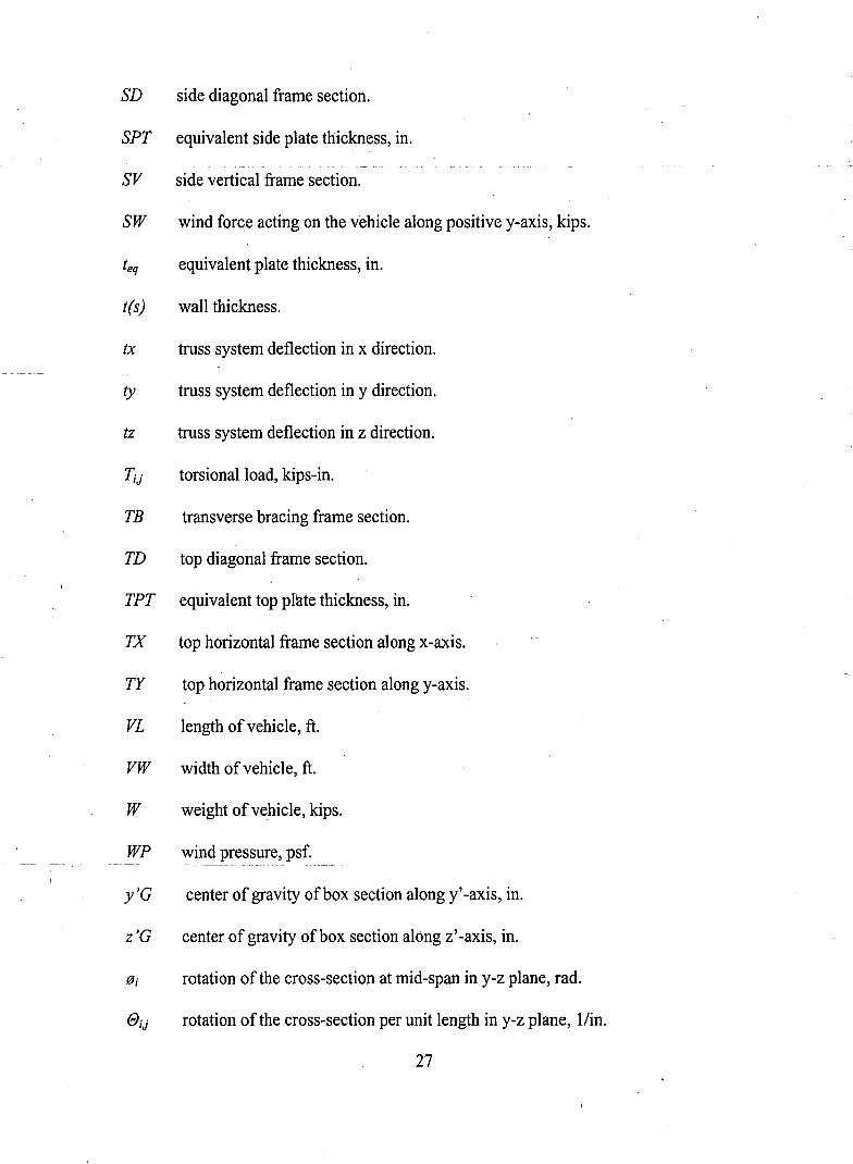
SD side diagonal frame section.
SPT equivalent side plate thickness, in.
SV side vertical frame section.
SW wind force acting on the vehicle along positive y-axis, kips.
teq equivalent plate thickness, in.
t(s) wall thickness.
tx truss system deflection in x direction.
ty truss system deflection in y direction.
tz truss system deflection in z direction.
TiJ torsional load, kips-in.
TB transverse bracing frame section.
TD top diagonal frame section.
TPT equivalent top plate thickness, in.
TX top horizontal frame section along x-axis.
TY top horizontal frame section along y-axis.
VL length ofvehicle, ft.
VW width ofvehicle, ft.
W weight ofvehicle, kips.
WP wind pressure, psf.
y'G center of gravity ofbox section along y' -axis, in.
z 'G center of gravity of box section along z'-axis, in.
B; rotation of the cross-section at mid-span in y-z plane, rad.
e;J rotation of the cross-section per unit length in y-z plane, Ifin.
27
N00
Case 1 Member Member Cross-Section Sectional Area (in2)
TX TS20X12X1/2 30.40TY. TS6X6X3/16 4.27TD TS10X8X1/4 8.59BX TS20X12X5/8 37.40BY TS12X8X3/16 7.27BD TS10X4X3/16 5.021B TS7X7X3/16 5.02SV TS14X6X1/4 9.59SD TS10X10X3/8 14.10
MemberLength (in)
240.0080.52.
243.35240.0080.52243.35113.50
. 80.00252.98
Number of Total Member Total Member Total MemberMembers Length (in) Volume On3) Weight (kips)
8 1920.00 58368.00 16.555 402.60 1719.10 0.498 1946.80 16723.01 4.748 1920.00 71808.00 20.365 402.60 2926.90 0.838 1946.80 9772.94 2.7710 1135.00 5697.70 1.6210 800.00 7672.00 2.188 2023.84 28536.14 8.09
203223.80 57.63
Load TransferFull Conversion
Partial Conversion
Total Member Weight (kips)20.7117.22
Span Load (kips/in)0.010790.00897
Note: TMWFc = Total Member Weight for Full Conversion = WTY+Wm+WBy+WSD+WTB+WSv+WsD and S[ = TMWFc / (2*960)TMWpc = Total Member Weight for Partial Conversion = WTD+WBD+WTB+WSD and SL = TMWpc / (2*960)
Table 3.1.1 Truss member sections, total weight of truss system and load transfervalues from truss system to the converted box girder of Case I .
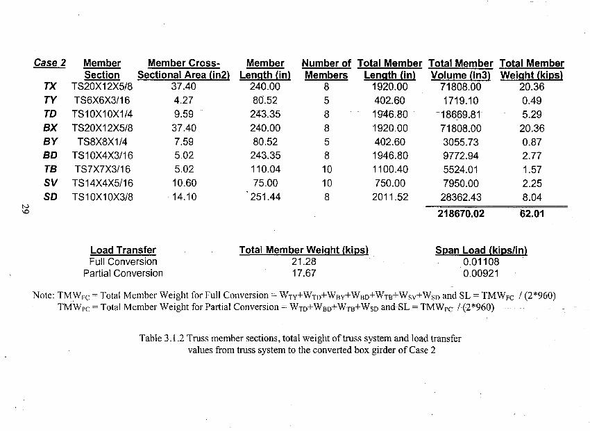
Case 2 Member Member Cross- Member Number of Total Member Total Member Total MemberSection Sectional Area (in2) Length (in) Members Length (in) Volume (in3) Weight (kips)
TX TS20X12X5/8 37.40 240.00 8 1920.00 71808.00 20.36TY TS6X6X3/16 4.27 80'.52 5 402.60 1719.10 0.49TO TS10X10X1/4 9.59 243.35 8 1946~80 ··18669~81 5.29BX TS20X12X5/8 37.40 240.00 8 1920.00 71808.00 20.36BY TS8X8X1/4 7.59 80.52 5 402.60 3055.73 0.87BO TS1OX4X3/16 5.02 243.35 8 1946.80 9772.94 2.77TB TS7X7X3/16 5.02 110.04 10 1100.40 5524.01 1.57SV TS14X4X5/16 10.60 75.00 10 750.00 7950.00 2.25SO TS10X10X3/8 14.10 251.44 8 2011.52 28362.43 8.04
tv\0 218670.02 62.01
Load TransferFull Conversion
Partial Conversion
Total Member Weight (kips)21.2817.67
Span Load (kips/in)0.011080.00921
Note: TMWFc = Total Member Weight for Full Conversion = WTY+WTD+WBy+WBO+WTB+WSY+Wso and SL = TMWFc / (2*960)TMWpc = Total Member Weight for Partial Conversion = WTD+WBO+WTB+WSO andSL= TMWpc 1{2*960)
Table 3.1.2 Truss member sections, total weight of truss system and load transfervalues from truss system to the converted box girder of Case 2
VJo
Case 3 MemberSection
TX TS20X12X5/8TY TS6X6X3/16TO TS10X10X1/4BX W33X141BY TS10X8X1/4BO TS10X5X3/16TB TS8X6X3/16SV TS12X8X5/16SO TS12X12X5/16
Member Cross-Sectional Area (in2)
37.404.279.59
41.608.595.395.0211.9014.40
MemberLength (in)
240.0080.52
243.35240.0080.52
243.35106.6970.00
250.00
Number of Total Member Total Member Total MemberMembers Length (in) Volume (in3) Weight (kips)
8 1920.00 71808.00 20.365 402.60 1719.10 0.498 1946.80 18669.81 5.298 1920.00 79872.00 22.655 402.60 3458.33 0.988 1946.80 10493.25 2.9810 1066.90 5355.84 1.5210 700.00 8330.00 2.368 2000.00 28800.00 8.17
228506.34 64.80
Load TransferFull Conversion
Partial Conversion
Total Member Weight (kips)21.7917.96
Span Load (kips/in)0.01135
.0.D0935
Note: TMWFc = Total Member Weight for Full Conversion = WTY+WTD+WBy+WBO+WTB+WSV+Wso and SL = TMWFc 1(2*960)TMWpc = Total Member Weight for Partial Conversion = Wm+WBo+WTB+WSO and SL == TMWpc ~(2~~0) _
Table 3.1.3 Truss member sections, total weight of truss system and load transfervalues from truss system to the converted box girder of Case 3
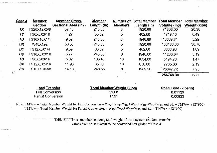
Case 4 Member Member Cross- Member Number of Total Member Total Member Total MemberSection Sectional Area (in2) Length (in) Members Length (in) Volume (in3) Weight (kips)
TX TS20X12X5/8 37.40 240.00 8 1920.00 71808.00 20.36TY TS6X6X3/16 4.27 80.52 5 402.60 1719.10 0.49TD TS10X10X1/4 9.59 243.35 8 1946.80 18669.81 5.29BX W40Xt92 56.50 240.00 8 1920.00 108480.00 30.76BY TS12X8X1/4 9.59 80.52 5 402.60 3860.93 1.09BD TS1OX6X3/16 5.77 243.35 8 1946;80 11233.04 3.19TB TS8X6X3/16 5.02 103.48 10 1034.80 5194.70 1.47SV TS12X8X5/16 11.90 65.00 10 650.00 7735.00 2.19SD TS10X10X3/8 14.10 248.65 8 1989.20 28047.72 7.95
w
256748:30 72.80
Load TransferFull Conversion
Partial Conversion
Total Member Weight (kips)21.6817.91
Span Load (kips/in)0.011290.00933
Note: TMWFc = Total Member Weight for Full Conversion = WTy+WTD+WBy+WBD+WTB+WSV+WSD and SL = TMWFc / (2*960)TMWpc = Total Member Weight for Partial Conversion = WTD+WBO+WTB+Wso and SL = TMWpc / (2*960)
Table J:T)llruss-memb-ersectiOlis:-total weight of truss system and load transfervalues from truss system to the converted box girder of Case 4
wN
Case 5 Member Member Cross-Section Sectional Area (in2)
TX TS20X12X5/8 37.40TY TS8X8X3/16 5.77TD TS10X10X1/4 9.59BX TS20X12X5/8 37.40BY TS10X8X1/4 8.59BD TS7X7X3/16 - 5.02TB TS10X8X3/16 6.52SV TS8X8X5/16 9.36SD TS10X10X3/8 14.10
MemberLength (in)
240.0080.52243.35240.0040.26240.84100.2382.49253.78
Number ofMembers
85885810108
Total Member Total Member Total MemberLength (i'n) Volume (in3) Weight (kips)
1920.00 71808.00 20.36402.60 2323.00 0.661946.80 18669.81 5.291920.00 71808.00 20.36·201.30 1729.17 0.491926.72 9672.13 2.741002.30 6535.00 1.85824.90 7721.062.192030.24 28626.38 8.12
218892.56 62.07
Load TransferFull Conversion
Partial Conversion
Total Member Weight (kips)21.3518.01
Span Load (kips/in)0.011120.00938 .. ,. ~ .. .......
Note: TMWFc = Tot&.I Member Weight for Full Conversion = WTY+Wm+WBy+WBD+WTB+Wsv+WsD.and SL = TMWFc / (2*960)TMWpc = Total Member Weight for Partial Conversion = Wm+WBo+WTB+WSO and SL = TMWpc / (2*960)
Table 3.1.5 Truss member sections, total weight of truss system and load transfervalues from truss system to the converted box girder of Case 5
ww
Case 6 Member Member Cross-Section . Sectional Area (in2)
TX . TS20X12X5/8 37.40TY TS8X8X3/16 5.77
TD TS10X10X1/4 9.59BX W40X149 43.80BY TS1 OX8X1 14 8.59
BD TS8X6X3/16 5.02fB .TS12X6X3/16 6.52SV TS10X10X1/4 9.59SD TS10X10X3/8 14.10
MemberLength (in)
240.0080.52
243.35240.0040.26
240.8496.2977.65252.25
Members85885810
108
.Length (in)1920.00402.60
1946.801920.00201.301926.72962.90776.502018.00
Volume (in3)71808.00
2323.00
18669.8184096.001729.1]9672.136278.117446.6428453.80
230476.66
Weight (kips)20.36
0.66
5.2923.85
0.492.741.782.118.07
65.36
Load TransferFull Conversion
Partial Conversion
Total Member Weight (kips)21.1517.89
Span Load (kips/in)0.011010.00932
Note: TMWFc = Total Member Weight for Full Conversion = WTy+WTD+WBy+WBD+WTB+WSV+WSD and SL= TMWFc / (2*960)TMWpc = To'tal Member Weight for Partial Conversion = WTD+WBD+WTB+WSD and SL = TMWpc / (2*960)
Table 3.1.6 Truss member sections, total weight of truss system and load transfervalues from truss system to the converted box girder ofCase 6
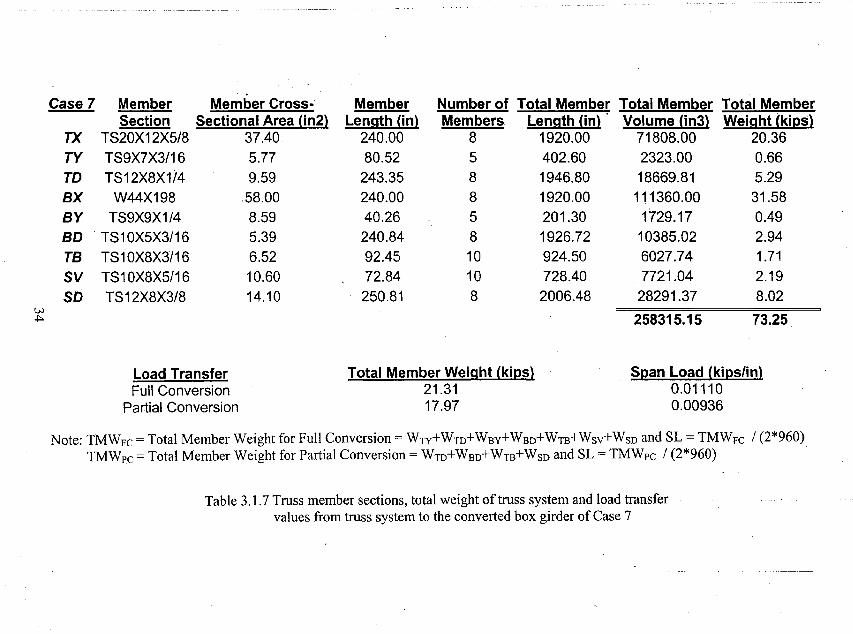
Case 7 Member Member Cross-' Member Number of Total Member Total Member Total MemberSection Sectional Area (in2) Length (in) Members Length (in) Volume (in3) Weight (kips)
TX TS20X12X5/8 37.40 240.00 8 1920.00 71808.00 20.36TY TS9X7X3/16 5.77 80.52 5 402.60 2323.00 0.66TD TS12X8X1/4 9.59 243.35 8 1946.80 18669.81 5.29BX W44X198 58.00 240.00 8 1920.00 111360.00 31.58BY TS9X9X1/4 8.59 40.26 5 201.30 1729.17 0.49BD TS10X5X3/16 5.39 240.84 8 1926.72 10385.02 2.94TB TS10X8X3/16 6.52 92.45 10 924.50 6027.74 1.71SV TS1OX8X5/16 10.60 72.84 10 728.40 7721.04 2.19SO TS12X8X3/8 14.10 250.81 8 2006.48 28291.37 8.02
V.>~ 258315.15 73.25
Load TransferFull Conversion
Partial Conversion
Total Member Weight (kips)21.3117.97
Span Load (kips/in)0.011100.00936
Note: TMWFc = Total Member Weight for Full Conversion = WTY+Wro+WBy+WBD+WTB+WSy+WSD and SL = TMWFc 1(2*960)TMWpc = Total Member Weight for Partial Conversion = Wro+WBD+WTB+WSD and SL = TMWpc / (2*960) .
Table 3.1.7 Truss member sections, total weight of truss system and load transfervalues from truss system to the converted box girder of Case 7
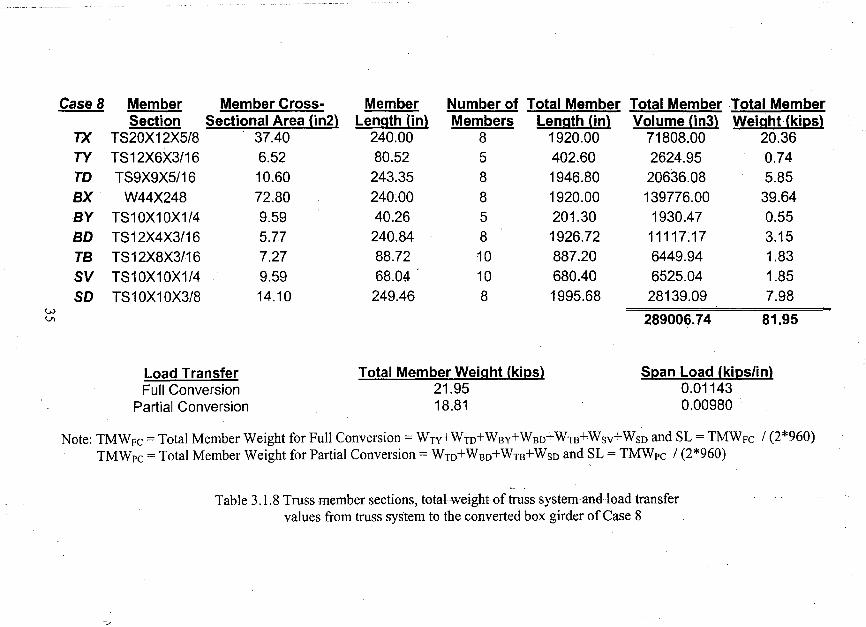
CaseB Member Member Cross- Member Number of Total Member Total Member Total MemberSection Sectional Area (in2) Length (in) Members Length (in) Volume (in3) WeighHkips)
TX TS20X12X5/8 37.40 240.00 8 1920.00 71808.00 20.36TY TS12X6X3/16 6.52 80.52 5 402.60 2624.95 0.74TO TS9X9X5/16 10.60 243.35 8 1946.80 20636.08 5.85
BX W44X248 72.80 240.00 8 1920.00 139776.00 39.64
BY TS10X10X1/4 9.59 40.26 5 201.30 1930.47 0.55
BO TS12X4X3/16 5.77 240.84 8 1926.72 11117.17 3.15
TB TS12X8X3/16 7.27 88.72 10 887.20 6449.94 1.83
SV TS10X10X1/4 9.59 68.04 10 680.40 6525.04 1.85
SO TS1 OX1 OX3/8 14.10 249.46 8 1995.68 28139.09 7.98w
289006.74 81.95Vl
Load TransferFull Conversion
Partial Conversion
Total Member Weight (kips)21.9518.81
Span Load (kips/in)0.011430.00980 .
Note: TMWFc = Total Member Weight for Full Conversion = WTY+WTD+WBy+WBO+WTB+WSY+Wso and SL = TMWFc / (2*960)TMWpc = Total Member Weight for Partial Conversion = WTD+WBO+WTB+WSO and SL = TMWpc / (2*960)
Table 3.1.8 Truss member sections, total weight of truss system and load transfervalues from truss system to the converted box girder of Case 8
"7
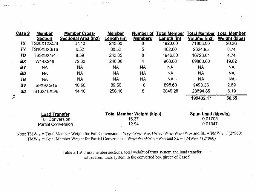
Case 9 Member Member Cross- Member Number of Total Member Total Member Total MemberSection Sectional Area (in2) Length (in) Members Length (in) Volume (in3) Weight (kips)
TX TS20X12X5/8 37.40 240.00 8 . 1920.00 71808.00 20.36TY TS10X8X3/16 6.52 80.52 5 402.60 2624.95 0.74TO TS9X9X1/4 . 8.59 243.35 8 1946.80 16723.01 4.74BX W44X248 72.80 240.00 4 960.00 69888.00 19.82BY NA NA NA NA NA NA NABO NA NA NA NA NA NA NATB NA NA NA NA NA NA NA~
SV TS9X9X5/16 10.60 89.56 10 895.60 9493.36 2.69SO TS10X10X3/8 14.10 256.16 8 2049.28 28894.85 8.19
w0-, 199432.17 56.55
Load Transfer Total Member Weight (kips) Span Load (kips/in)Full Conversion 16.37 0.01705
Partial Conversion 12.94 0.01347
Note: TMWFc = Total Member Weight for Full Conversion =: WTy+WTD+WBy+WBD+WTB+WSV+WSD and SL = TMWFc / (2*960)TMWpc = Total Member Weight for Partial Conversion = WTD+W~D+WTB+WSD and SL = TMWpc / (2*960)
Table 3.1.9 Truss member sections, total weight of truss system and load transfervalues from truss system to the converted box girder of Case 9
W--..l
Case 10
TXTYTD
BXBYBDTBSVSD
MemberSection
TS20X12X5/8TS10X8X3/16TS10X10X1/4
W40X362NANANA
TS10X10X5/16TS10X10X3/8
Member CrossSectional Area (in2)
37.406.529.59
106.00NANANA
11.9014.10
MemberLength (in)
240.0080.52243.35240.00
NANANA.
85.12254.64
Number of Total MemberMembers Length (in)
8 1920.005 402.608 1946.804 960.00
NA NANA NANA NA10 851.208 2037.12
Total Member Total MemberVolume (in3) Weight (kips)
71808.00 20.362624.95 0.7418669.81 5.29101760.00 28.86
NA NANA NANA NA
10129.28 2.8728723.39 8.14
233715.44 66.27
Load TransferFull Conversion
Partial Conversion
Total Member Weight (kips)17.0613.44
Span Load (kipslin)0.0177,70.01400
Note: TMWFc = Total Member Weight for Full Conversion = WTY+Wm+WBy+WBD+WTB+WSV+WSD and SL = TMWFc / (2*960)TMWpc = Total Member Weight for Partial Conversion = Wm+WBD+WTB+WSD and SL = TMWpc / (2*960)
Table 3.1.10 Truss member sections, total weight oftruss system and load transfervalues from truss system to the converted box girder of Case 10
w00
Case 11
TXTYTDBXBYBDTBSVSD
MemberSection
TS20X12X5/8TS 12X8X3/16TS10X10X1/4
W40X531NANANA
TS10X10X5/16TS12X8X3/8
Member CrossSectional Area (in2)
37.407.279.59
156.00NANANA
11.9014.10
MemberLength (in)
240.0080.52243.35240.00
NANANA
80.75253.22
Number of Total Member. Total Member Total MemberMembers Length (in) Volume (in3) Weight (kips)
8 1920.00 71808.00 20.365 402.60 2926.90 0.838 1946.80 18669.81 5.294 960.00 149760.00 42.47
NA NA NA NANA NA NA NANA NA NA NA10 807.50 9609.25 2.728 2025.76 28563.22 8.10
281337.18 79.78
Load TransferFull Conversion
Partial Conversion
Total Member Weight (kips)16.9513.39
Span Load (kips/in)0.017650.01395
Note: TMWFc =Total Member Weight for Full Conversion = WTy+WTD+WBy+WBD+WTB+WSV+WSD and SL =TMWFc 1(2*960)TMWpc = Total Member Weight for Partial Conversion = WTD+WBD+WTB+WSD and SL =TMWpc 1(2*960)
Table 3.1.11 Truss member sections, total weight of truss system and load transfervalues from truss system to the converted box girder of Case II
Case 12 Member Member Cross- Member Number of Total Member Total Member Total MemberSection Sectional Area (in2) Length (in) Members Length (in) Volume (in3) Weight (kips)
TX TS20X12X5/8 37.40 240.00 8 1920.00 71808:00 20.36
TY TS12X8X3/16 7.27 80.52 5 402.60 2926.90 0.83
TD TS10X10X5/16 11.90 243.35 8 1946.80 23166.92 6.57
BX W40X655 192.00 240.00 4 960.00 184320.00 52.27
BY NA NA NA NA NA NA NABD NA NA NA NA NA NA NATB NA NA NA NA NA NA NASV TS10X10X5/16 11.90 76.46 10 764.60 9098.74 2.58SD TS12X8X3/8 14.10 251.88 8 2015.04 28412.06 8.06
w'0 319732.63 90.66
Load Transfer Total Member Weight (kips) Span Load (kips/in)Full Conversion 18.04 0.01879
Partial Conversion 14.63 0.01524,
. Note: TMWFc = Total Member Weight for Full Conversion = WTy+WTD+WBy+WBO+WTB+WSY+Wso and SL = TMWFc / (2*960)TMWpc = Total Member Weight for Partial Conversion = WTD+WBO+WTB+WSO and SL = TMWpc / (2*960)
Table 3.1.12 Truss member sections, total weight of truss system and load transfervalues from truss system to the converted box girder of Case 12
r
r
Case TPT (in) BPT (in) OPT (in) SPT (in) Ax (in2) Ix (in4) ~ Iz (in4) bY...li!:!l Hz (in)~ z'G (in) W (kips/in) TW (kips)1 0.01491 0.00872 0.11453 0.04330 144.43 16372.8 228978.4 235350.9 92.52 100 46.26 -43.74 0.04 39,32l' 0.01402 0.00848 0.09372 0.02928 142.1 15337.7 227588.6 231667.7 92.52 100 46.26 -43.82 0.04 38.682 - 0.01665 0.00872 0.11453 0.04330 158.14 16356.7 224286.7 257724.6 92.52 95 46.26 -37.35 0.04 43.052' 0.01569 0.00848 0.09398 0.03029 156.09 15491.2 223237.8 254511.5 92.52 95 46.26 -37.36 0.04 42.493 0.01665 0.00936 0.11453 0.04422 166.28 11690 217092.4 269559.1 92.52 96.65 46.26 -36.64 0.05 45.273' 0.01569 0.00912 0.09469 0.03122 164.37 10926.5 216218.9 266558 92.52 96.65 46.26 -36.68 0.05 44.754 0.01665 0.01002 0.11453 0.04330 195.58 10943.6 225950.4 318026.2 98.23 94,1 46.26 -38.76 0.06 53.244' 0.01569 0.00980 0.09527 0.03191 194 10332.7 225242.6 315576.7 98.23 94.1 46.26 -38.82 0.06 52.815 0.01665 0.00872 0.14875 0.04330 158.4315077.2 253865.1 162690.8 92.52 100 46.26 -39.75 0.04 43.135' 0.01577 0.00849 0.12145 0.03029 156.21 14143.2 252593.6 160622.9 92.52 100 46.26 -39.76 0.04 42.526 0.01665 0.00872 0.14875 0.04330 170.82 10326.4 256316.3 166131.392.52 104.1 46.26 -40.09 0.05 46.506' 0.01577 0.00851 0.12145 0.03097 168.82 9560.8 255281.7 164282.4 92.52 104.1 46.26 -40.14 0.05 45.967 0.01665 0.00936 0.14875 0.04330 198.82 9775.5 265833.4 177462.4 92.52 101.45 46.26 -42.08 0.06 54.12
~ 7' 0.01577 0.00917 0.12145 0.03200 197.2 9183.6 264990.2 175956.8 92.52 101.45 46.26 -42.15 0.06 53.680 8 0.01840 0.01002 0.16586 0.04330 228.18 9442 261159.8 189342.3 92.52 96.81 46.26 -42.43 0.06 62.12
8' 0.01736 0.00984 0.13563 0.03268 226.64 8880 260352.6 187930 92.52 96.81 46.26 -42.51 0.06 61.709 0.01491 0.00000 0.00000 0.04330 156.56 8411.2 267511.6 128321.1 92.52 111.81 46.26 -39.18 0.04 42.629' 0.01422 0.00000 1.24986 0.03268 154.6 7783.8 266410.6 127263.6 92.52 111.81 46.26 -39.19 0.04 42.0910 0,01665 0.00000 0.00000 0.04330 189.51 8284.7 285873.3 129134.1 92.52 105.27 46.26 -43.41 0.05 51.5910' 0.01579 0.00000 1.24986 0.03355 187.78 7710.6 284907 128200.8 92.52 105.2746.26 -43.48 0.05 51.1211 0.01665 0.00000 0.00000 0.04330 239.13 8058 302856.4 129749.6 92.52 101.17 46.26 -46.69 0.07 65.1011' 0.01581 0.00000 1.39363 0.03420 237.6 7586.2 301907 128919.3 92.52 101.17 46.26 -46.77 0.07 64.6812 0.02066 0.00000 0.00000 0.04330 275.08 8315.4 295139.1 130383.2 92.52 96.81 46.26 -46.15 0.08 74.8812' 0.01939 0.00000 1.39363 0.03446 273.63 7817 294191.4 129597.9 92.52 96.81 46.26 -46.23 0.08 74.49
Note: prefix Ly for cross-sectional dimension in y direction, Hz for_Foss-sectional dimension in z direction, y'G for center of gravityof box section along y'-axis, z'G for center of gravity of box section along z'-axis, W for weight, TW for total weight.
Table 3.2.1 Equivalent top, bottom, diaphragm and side plate thicknesses and cross sectional properties of converted box sections
r
Finite Element AnalysisCase
1234
"AverageOisplacement (in)Average Displacement Ratio
5678
< A,verageQ/splacement (in)~Average Displacement Ratio~ 9
101112
Average 'pisplacement (in)AveragfjOispiacement Ratio
bx0.140.150.130.110.130.930.130.120.100.100.110.990.120.110.100.100.111.02
b'x tx Qy0.14 0.15 0.370.14 0.16 0.340.13 0.14 0.340.09 0.11 0.31
-,().12 '••. qL143: ·'().340.88' "1;00; 0;900.13 0.14 0.500.11 0.12 0.530.09 0.10 0.520.09 0.09 . 0.48°i1 () ""'. OV11'Oi51'"0.92 1.00 0.890.11 0.13 0.600.10 0.11 0.560.09 0.09 0.540.09 0.09 ,0.47'0.10:P"tP ;1:,Q;.~.40.93' 1.00 '0;91
.!iv0.580.530.500.460.521.370.890.850.810.730:821.440.860.810.830.730.811.35
Classical Method!Y bz biz tz bz biz
0.41 -1.10 -1.57 -1.14 -0.81 -0.82,0.38 -1.15 -1.61- -1.19 -0.82 -0.830.37 -1.15 -1.54. -1.19 -0.90 -0.920.35 -1.09 -1.41 -1.19 -0.91 -0.92b.3ff':."1:t2' .,;-1;53-t.18-0.86.'.··., -0:8'7;"
. 1.00 "'0;96 '. '10'30-"- ~4;09- ~"0;-7~-'--"~"'"l4-~'0.56 -1.16 -1.70 -1.17-,;;(t76---;;;ft:'7'"r--6.60 -1.15 -1.59 -1.17 -0~82 -0.840.58 -1.14 -1.54 -1.17 -0.83· -0.850.53 '-1.13 -1.51 -1.18 -0.87 -0.880;57'::1'.1'4,';."1.59' '-1'.17 ..([82' -,', "()]~47i
1.000.98 1.35 1.00 0.70 0.71"0.66 -1.18 -1.60 -1.20 -0.83 -0.850.61 -1.17 -1.59 -1.19 -0.82 -0.850.59 -1.15 i -1.59 ,.1.18' -0.83 ";0.85,0.53 -1.15 -1.-58 -1.18 -0.85 -0.87bi60' '21.'16 ";1.59 ..1A9';':().83':0:S5'1.00 ;;0:98 1~34' 1.00 0.70 '. 0.72
A~~t~,;~eE:t~~t~::h~~~h61 ~:~~ ~:~~ ,~:6~,I,i~i~~0.711.39
0.51" '/-1.14., -1.571-1.181' -0.841.00 0.97 1.33 1.00 0.71
-(),85 '0;73
Note: prefix band b' for partially and fully converted box girders, t for, truss systems.
Table 4.1.1 Deflections by Finite Element Analysis and Classical Method in x, yand z directions under design load
Finite Element Analysis Classical MethodCase bx b'x tx ~ ~ ~ bz b'Z tz bz b'z
1 0.14 0.13 0.15 0.36 0.57 0.40 -1.10 -1.56 -1.13 -0.79 -0.802 0.15 0.15 0.16 0.34 0.62 0.37 -1.14 -1.75 -1.18 -0.81 -0.823 0.13 0.13 0.14 0.33 0.49 0.37 -1.14 -1.52 -1.18 -0.88 -0.904 0.11 0.09 0.11 0.31 0.45 0.35 -1.08 -1.39 -1.18 -0.89 -0.90
.Al!er;~ge Displacement (in) 0.13 . 0.12 0.14 0.;34',0;53 0.37< -'1.12 ~1.55 -1.17 -0.84" -0.86Average Displacement RatiO ----0:93 0.88 1.00 0.90 1.42 1.00 0.96 1.33 1.00 0.72 0.73-5-- 0.13 0.13 0.14 0.49 0.86 0.55 -1.15 -1.68 -1.16 -0.74 -0.75
6 0.12 0.10 0.12 0.52 0.82 0.59 -1.13 -1.57 -1.16 -0.80 )-0.827 0.10 0.09 0.10 . 0.51 0.78 0.57 -1.13 -1.51 -1.16 -0.81 '-0.828 0.10 0.09 0.09 0.47 0.71 0.52 -1.12 -1.49 -1.16 -0.84 -0.86
Average Displacement (in) 0.11 0.10 0.1'1 0.50 0.79 0.56 21d3 ..1.56 ~-1.16 -0.80 ~ojH
~ Average Displacement Ratio 1.00 0;92· 1.00 0.89 1.42 1.00 0.98 1.35 1.00 0.69 0;70tv 9 0.12 0.11 0.13 0.58 0.83 0.64 -1.16 -1.56 -1.18 -0.80 -0.82
10 0.11 0.10 0.11 0.54 0.78 0.59 -1.15 -1.56 -1.17 -0.80 ..0.8211 0.10 0.09 0.09 0.52 0.79 0.57 -1.14 -1.55 -1.16 -0.80 -0.8212 0.10 0.09 0.09 0.46 0.70 0.52 -1.14 -1.55 -1.17 -0.82 -0.84
Ave/J#ge Displacement (in) 0.11 0.10' 0.10 0.53 0.77' 0.58 '~1i15' ':1.55. -1~17 ~0.81 ;.().8:2 i.
AverageDispiacement Ratio 1.03 0.94 1.00 0.91 1;33 1.00 0.98 . 1~33 1.00 6.69 0.71
Avef1i.!!eplsplac,ement (in) I 0.12 0.11~:~~ I~i:~"
0.70~:~~-1-~.~:-L;:1-11.~~I ~g,:; -():83
AverageDisplacement Ratio 0.98 "0.91 1.39;; 0.71
Note: prefix band b' for partially and fully converted box girders, t for truss systems.
Table 4.1.2 Deflections by Finite Element Analysis and Classical Method in x, yand z directions under a tOTsionalload decrement of (1 0%)
Finite Element Analysis Classical MethodCase bx b'x tx .Qy !tv tv bz b'z tz bz b'z
1 0.14 0.13 0.15 0.36 0.55 0.40 -1.09 -1.54 -1.12 -0.78 -0.792 0.14 0.14 0.16 0.33 0.51 0.37 -1.13 -1.58 -1.17 -0.80 -0.803 ~ 0.13 0.12 0.14 0.33 0.48 0.36 -1.13 -1.51 -1.17 -0.87 -0.884 0.11 0.09 0.11 0.31 0.44 0.34 -1.07 -1.38 -1.17 -0.87 -0.88
Average Displacement (in) 0.13 0.12 0.14 0.33 0.49 0.37 -1.11 -1.50 -1.16 -0.83 -0:84Average Displacement Ratio 0.93 0.87 1.00 0.90 1.35 1.00 0.96 1.30 1.00 0.71 0.72
5 0.13 0.13 0.14 0.48 0.83 0.54 -1.14 -1.65 -1.15 -0.73 -0.74.(j 0.12 0.11 0.12 0.51 0.79 0.57 -1.12 -1.54 -1 .. 14 -0.78 -0.807 0.10 0.09 0.10 0.49 0.75 0.56 -1.12 -1.49 -1.14 -0.79 -0.808 0.10 0.09 0.09 0.45 0.68 0.51 -1.11 -1.46 -1.15 -0.82 -0.83
Average Displacement (in) 0.11 0.10 0.11 0.48 0.76 0.54 -1:12 ~1.53 -1.15 -0.78 -0.79~ Average Displacement Ratio 1.00 0.93 1.00 0.89 1.41 1.00 0.98 1.34 1.00 0.68 0.69w 9 0.12 0.11 0.13 0.56 0.79 0.62 -1.15 -1.53 -1.17 ' -0.78 -0.80
10 0.11 0.10 0.11 0.52 0.75 0.58 -1.13 -1.52 -1.15 -0.77 -0.7911 0.10 0.09 0.09 0.50 0.76 0.55 -1.12 -1.52 -1.14 -0.77 -0.7912 0.10 0.09 0.08 0.45 0.67 0.50 -1.12 -1.51 -1.15 -0.79 -0.81
Average Displacement (in) 0.11 0.10 0.10 0.51 0.74 0.56 -1.13 -1.52 -1.15 -0.78 -0.80Average Displacement Ratio 1.03 0.94 1.00 0.90 1.32 1.00 0.98 1.32 1.00 0.67 0.69
Avera,geDisplacement (in) I0.12 0.11 0.121 0.44 0.67 0.49 1-1.12 -1.521-1.151 -0.79 -0.8.1
Average Displacement Ratio 0.98 0.91 1.00 0.90 1.36 1.00 0.97 1.32 1.00 0.69 0.70
Note: prefix band b' for partially and fully converted box girders, t for truss systems.
Table 4.1.3 Deflections by Finite Element Analysis and Classical Method in x, y .and z directions under a torsional load decrement of (20%)
Finite Element Analysis Classical MethodCase bx b'x tx .!ri !ll ~ bz b'z . tz bz b'z
1 0.14 0.14 0.15 0.37 0.59 0.41 -1.11 -1.59 -1.15 -0.82 -0.832 0.15 0.15 0.16 0.34 0.54 0.38 -1.16 -1.63 -1.20 -0.83 -0.853 0.13 0.13 0.14 0.34 0.51 0.38 -1.16 -1.56 -1.20 -0.92 -0.944 0.11 0.09 0.11 0.32 0.46 0.36 -1.10 -1.42 -1.20 -0.93 -0.94
Average Displacement (in) 0.13 0.12 0.14 0.34 0.53 0.38 -1.13 -1.55 -1.19 -0.88 -0.89Average Displacement Ratio 0.93 0.88 1.00 0;90 1.37 1.00 0.96 1.31 1.00 0.74 0.75
5 0.13 0.13 0.14 0.51 0.91 0.57 -1.17 -1.73 -1.18 -0.77 -0.78 .6 0.11 0.11 0.12 0.55 0.87 0.61 -1.16 -1.62 -1.18 -0.85 -0.877 0.10 0.09 0.10. 0.53 0.83 0.60- -1.16 -1.57 -1.18 -0.86 . -0.878 0.10 0.09 0.09 0.49 0.75 0.54 -1.15 -1.54 .,1.19 -0.89 -0.91
Average Displacement (in) 0.11 0.10 0.11 '0.52 0.84 0.58" -1.16 -1.61 -1.18 ::'0.84" " -0.86~ Average Displacement Ratio 0.99 0.92 1.00 0.90 1.45 1.00 0.98 1.36 1.00 0.71 0.72~ 9 0.12 0.11 0.13 0.62 0.89 0.68 -1.20 -1.63 -1.22 -0.85 -0.88
10 0.11 0.10 0.11 0.57 0.84 0.63 -1.19 -1.63 -1.20 -0.85 -0.8711 0.10 0.09 0.09 0.55 0.86 O.6p -1.17 -1.63 -1.19 -0.86 -0.8812 0.10 0.09 0.09 0.49 0.76 0.55 -1.17 -1.62 -1.20 -0.88 -0.90
Average Displacement (in) 0.11 0.10 0.10 O~56 0.84 0.61 -.1.18 -1.63 -1,20 :0.86 . -0:88Average Displacement Ratio 1.02 0.93 1.00 0.91 1.37 1.00 0.98 1.35 1.00 0.72 0.73
AVElr~g~Displacement(in) I 0.12 0.11 O.1?1.9,.4~ 0.74 0.5.3 T:1.H> -1.60 I-L19<1 '-0.86 -0.88Average Displacement Ratio 0.97 0.91 1.00 0.90 1.40 1.00 0.97 1.34 1.00 0.72 0.74
Note: prefix band b' for partially and fully converted box girders, t for truss systems.
Table 4.1.4 Deflections by Finite Element Analysis and Classical Method in x, yand z directions under a torsional load increment of(10%)
Finite Element Analysis Classical MethodCase bx b'x tx ~ !n tv bz biz tz bz biz
1 0.14 0.14 0.15 0.38 0.60 0.42 -1.12 -1.60 -1.15 -0.83 -0.852 0.15 0.15 0.16 0.35 0.55 0.39 -1.17 -1.65 -1.21 -0.85 -0.863 0.13 0.13 0.15 0.35 0.52 0.38 -1.17 -1.57 -1.21 -0.94 -0.964 0.11 0.09 0.11 0.32 0.47 0.36 -1.11 -1.44 -1.21 -0.95 -0.96
Av:~r;~geDisplacement (in) 0.13 . 0.13 0.14··.· 0.35 0.54 0:39> -1.14 -1.57 ;'1.20 . -0.89 ~0.91'Average Displacement Ratio 0.93 0.88 1.00 0.90 1.38 1.00 0.95 1.31 1.00 0.75 0.76·
5 0.13 0.13 0.14 0.53 0.94 0.59 -1.18 -1.75 -1.19 -0.78 -0.806 0.11 0.11 0.12 0.56 0.90 0.62 -1.17 -1.65 -1.20 -0.87 -0.897 0.10 0.09 0.10 0.55 0.86 0.61 -1.17 -1.59 -1.20 -0.88 -0.908 0.10 0.09 0.09 0.50 0.78 0.55 -1.16 -1.57 -1.21 ,.0.92 -0.94
Average Displacement (in) 0.11 0.10 0.11 ,0.53 0.87 0.59 -1.17 .,1.64- ~1;20 ·····;.0.86 ;.0~88
~Average Displacement Ratio 0.98 0.92 1,00 0.90 1.47 1.00 0.98 1.37 1.00 0.72 0.74VI 9 0.12 0.11 0.13 0.64 0.93 0.70 -1.22 -1.66 -1.23 -0.88 -0.91
10 0.11 0.10 0.11 0.59 0.88 0.64 -1.20 -1.66 -1.22 -0.88 -0.9011 0.10 0.09 0.09 0.57 0.89 0.62 -1.19 -1.67 -1.21 -0.89 -0.9112 0.10 0.09 0.09 0.50 0.79 0.56 -1.19 -1.66 -1.21 -0.91 -0.93
Average. Displacement (in) 0.11 0.10 {Oj10 '0.58 0.87 0.63 .,1.20 -1.66 -1.22 ':0.89 -0.911.00'
,.,; ',,",;
Average Displacement Ratio 1.02 0.93 1.00 0;91 1.38 1.00 0.98 1.36 0.73 0.75
Average Displacement (in) I 0.12 0.11 .,' 0.121°.49 0.76 0.54 \-1;17 -1.621 ~1.201 -0;88· -()j90Average Displacement Ratio 0.97 1.41 1.00 1.35 '. 1.00-.. 0;73 ·--0.15~
,0.91 1.00 . 0;91 0.97 -
Note: prefix band b' for partially and fully converted box girders, t for truss systems.
Table 4.1.5 Deflections by Finite Element Analysis and Classical Method in x, yand z directions under a torsional load increment of (20%)
Bending Stresses Shear StressesCase bx b'x tx !ri .!n ti bz biz tz
1 15.10 16.53 19.56 -1.45 -1.52 -1.61 -0.29 -0.29 -0.332 13.82 15.12 17.35 -1.21 -1.26 -1.35 -0.23 -0.23 -0.273 13.77 14.74 17.31 -1.18 -1.24 -1.36 -0.24 -0.22 -0.274 13.70 14.32 17.23 -1.17 -1.22 -1.38 -0.24 -0.22 -0.27
Average Stress (ksi) 14.10 _15.18 '17.86 -1.25 -1.31 ' ..1.43 -0.25 -0.24 -0.28Average Stress Ratio 0.79 0.85 '1.00 0.88 0.92 1.00 0.89 0.85 1.00
5 13.29 14.70 16.43 -1.14 -1.24 -1.24 -0.36 -0.22 -0.346 13.12 14.14 16.28 -1.15 -1.20 -1.27 -0.43 -0.22 -0.357 13.42 14.27 16.54 -1.13 -1.20 -1.26 -0.39 -0.22 -0.378 13.17 13.93 16.19 -1.14 -1.18 -1.30 -0.41 -0.22 -0.38
Average Stress (ksi) 13.25 14.26 16.36 -1.14 -1.21 -1.27 -0.40 ..0.22 -0.36"·~ Average Stress Ratio 0.81 0.87 1;00 0.90 0.95 1.00 1.10 ,. '0.61 1.00>0\
9 12.85 14.23 15.62 -1.13 -1.08 -1.23 -0.62 -0.23 -0.3710 12.95 14.24 15.63 -1.14 -1.08 -1.23 -0.70 -0.24 -0.3911 12.98 14.26 15.56 -1.14 -1.07 -1.24 -0.72 -0.24 -0.4012 12.84 13.94 15.25 -1.13 -1.07 -1.24 -0.74 -0.25 -0.39
Average Stress (ksi) 12.90 14.17 15;51 -1.14 -1~b7 -1.23 -0.69 -0.24 -().3~:Average'Stress Ratio 0.83 0.91 1.00 0.92 0.87 1.00 1.79 0.62 1.()0 ....
Average'Stress'lksi) I 13.42 14.53 16]58I-ci.~~
-1.20 -1.31
I-0.45 -0.23 1 -0;34 1
Averag13 StressRatio 0.81 0;88 "1.00 Ol91 1.00 1.30 0.68 1._QO •. ,~.
Note: prefix band b' for partially and fully converted box girders, t for truss systems.
Table 4.1.6 Bending and Shear Stresses by Finite Element Analysis under design load
Bending Stresses Shear StressesCase bx b'x tx Qy ~ ~ bz ' b'z tz
1 14.95 16.35 19.33 -1.42 -1.49 -1.58 -0.29 -0.28 -0.332 13.68 16.29 17.15 -1.19 -1.40 -1.32 -0.23 -0.23 -0.263 13.63 14.56 17.10 -1.16 -1.22 -1.34 -0.24 -0.22 -0.264 13.55 14.14 17.02 -1.15 -1.19 -1.36 -0.24 -0.22 -0.26
Average Stress' (ksi) 13.95 15.33 17.65 . -1.23 -1.32 -1.40 -0.25 -0.24 -0.28Average Stress Ratio 0.79 0.87 1.00 Q.88 0.94 1.00 0.90 0.85 1.00
5 13.17 14.51 16.25 ';1.11 -1.21 -1.21 -0.35 -0.22 -0.346 12.97 13.94 16.08 -1.12 -'1.18 -1.24 -0.42 -0.22 -0.357 13.26 14.07 16.33 -1.11 -1.17 -1.24 -0.38 -0.22 -'0.368 13.02 13.72 15.99 -1.12 -1.16 -1.28 -0.40 -0.22 -0.38
.AverageStress (ksi) 13.10 14.06 16.16 ~1.11 -1.18 -1.24 -0.39 -0.22 '~0.36~ 'Average Stress Ratio 0.81 0.87 1.00 ' 0.90 0.95 . 1:00 1.09 0.61 1.00 "-.J
9 12.67 13.99 15.41 -1.10 -1.05 -1.20 -0.60 -0.23 -0.3710 12.78 14.01 15.42 -1.12 -1.05 -1.21 -0.68 -0.23 -0.3911 12.81 14.01 15.36 -1.11 -1.05 -1.21 -0.70 -0.24 -0.39
'12 12.67 13.70 15.05 -1.11 -1.05 -1.22 -0.72 -0.23 -0.39AverCige Stress (ksi) , 12.73 13.93 15.31 -1.11 -1.05 -1.21 -0.67 -0.23 ;;"0.38Average'Stress'Ratio 0.83 0.91 1.00 0.92 0.87 1.00 1.75 0.61 1.00
fJ:Z::i~~:::k~1~113.26 14.44 16.37' I -1.15 -1.18 ~1;28
I-0.44
~::; I -0.34'0.81 0.88 1.00 0.90 0.92 1.00 1.28 1.00
Note: prefix band b' for partially and fully converted box girders, t for truss systems.
Table 4.1.7 Bending and Shear Stresses by Finite Element Analysis under a torsional load decrement of (10%)
Bending Stresses Shear StressesCase bx b'x tx .Qy Q:y ll! bz b'z tz
1 15.25 16.71 19.79 -1.48 -1.55 -1.64 -0.29 -0.29 -0.332 13.95 15.29 17.54 -1.23 -1.29 -1.37 -0.23 -0.23 -0.273 13.92 14.91 17.51 -1.21 -1.26 -1.39 -0.24 -0.22 -0.274 13.84 14.49 17.43 -1.20 -1.24 -1.41 -0.24 -0.22 -0.27
Average Stress (ksi) 14.24 ·15;35 18.07 -1.28 -1.33 -1.45 . -0.25 '-0;24 -0.28Average Stress Ratio 0.79 0.85 1.00 0.88 0.92 1;00 0.89 0.84 1.00
5 13.42 14.88 16.62 -1.16 -1.26 -1.26 -0.37 -0.22 -0.346 13.27 14.33 16.49 -1.17 -1.23 -1.29 -0.43 -0.22 -0.367 13.57 14.47 16.75 -1.15 -1.22 -1.28 -0.40 -0.22 -0.378 13.33 14.13 16.40 -1.16 -1.21 -1.33 -0.42 -0.22 -0.38
Average Stress (ksi) 13.40 14.45 16.56..
-1.16 -1.23 -1;29 -0.41 .' -0.22 -0;36~ Average Stress Ratio 0.81 0.87 1:00 . 0.90 0.95 1.00 1.12 0.61 1.001.0 9 13.02 14.46 15.82 -1.15 -1.10 -1.25 -0.64 -0.23 -0.38
10 13.12 14.48 15.82 -1.16 -1.10 -1.25 -0.72 -0.25 -0.3911 13.15 14.50 15.76 -1.16 . -1.10 -1.26 -0.74 -0.25 -0.4012 13.00 14.18 15.44 -1.16 -1.09 -1.27 -0.76 -0.27 -0.40
Average Stress (ksij 13.07 14.40 15.7.1.. :, -1.16 -1.10 -1.26 -0.71 }O.25 -0.39AveragiJ Stress Ratio 0.83 0.92 1.00 ,: 0.92 0.87 1.00 1.82 .,' 0;64 1.00
I-\verag(;,Stress (ksi) I 13.57 14.74 16.78 1 -1.20~.;;_. "'~11~:g_~I_~~~:: __~_~;::·I_-~~g__1Average.Stress Ratio 0.81 0.88 1.00 . 0.90
-Note: prefix band b' for partially and fully converted box girders, t for truss systems.
Table 4.1.9 Bending and Shear Stresses by Finite Element Analysis under a torsional load increment of (1 0%)

Bending Stresses Shear StressesCase bx b'x tx ID! ~ ~ bz b'z tz
1 15.39 16.90 20.01 -1.51 -1.58 -1.67 -0.30 -0.29 -0.332 14.08 15.46 17.74 -1.25 -1.31 -1.39 -0.24 -0.23 -0.273 14.06 15.08 17.72 -1.23 -1.29 -1.41 -0.24 -0.22 -0.274 13.98 14.66 17.63 -1.22 -1.26 -1.43 -0.24 -0.22 -0.27
,4ver8g~Stress (ksi) 14.38 15.52 18.27 -1.30 -1;36 ..1.48 -:0.25 -0.24" -0.29AveragiJStress'Ratio 0.79 0.85 1.00 0.88 0.92 1.00 0.89 0.84 1.00
5 13.56 15.06 16.80 -1.18 -1.29 -1.29 -0.38 -0.22 -0.346 13.42 14.53 16.69 -1.19 -1.25 -1.31 -0.44 -0.22 -0.367 13.73 14.67 16.96 -1.17 -1.25 -1.31 -0.41 -0.23 -0.378 13.48 14.33 16.60 -1.19 -1.23 -1.35 -0.43 -0.23 -0.38
AverageStress (ksi) 13.55 14.65 16.76 -1.18 .;.1.26 .;.1.31 -0.41 -0.23 -0.36'VI Average Stress Ratio 0.81 0.87 1.00 0.90 0.96 1.00 1.14. 0.62 1.00o 9 13.19 14.70 16.02 -1.18 -1.12 -1.28 -0.66 -0.25 -0.38
10 13.29 14.71 16.02 -1.19 -1.12 -1.28 -0.74 -0.27 -0.4011 13.32 14.74 15.95 -1.19 -1.12 -1.28 -0.76 -0.26 -0.4012 13.17 14.41 15.63 -1.18 -1.12 -1.29 -0.78 -0.29 -0.40
Average'Stress (ksi) 13.24 14.64 15.91 -1.18 ' .;.1.12 ~1.28 -0.73 -:027 -0.40 'Average Stress Ratio 0.83 0.92 1.00 ' 0.92 0.87 1.00 1.86 0.67 1.00
A..,~rlig~Stress(ksi) I 13.72 14.94 16.98
I-1.22 -1.25 -1.36'1 -0.47 -0.24 I -0.35
Average'StressRatio 0.81 0.88 4,00, 0.90 ,·Oi92 1.00 1.'34 0.70 .' 1.00
Note:. prefix band b' for partially and fully converted box girders, t for truss systems.
Table 4.1.10 Bending and Shear Stresses by Finite Element Analysis under a torsional load increment of (20%)
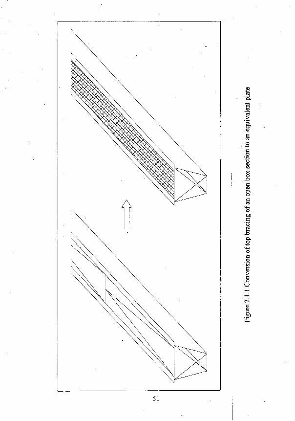
51
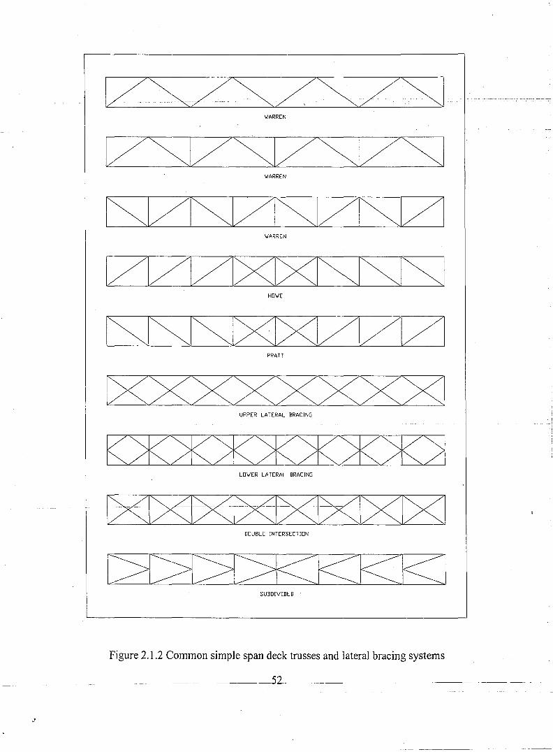
.)
IZSZSZSZSI . __ m _- ..- . --_... _. -- -- -....'._-" -----,--- . _. . .. ,-.__ .. _. -_. -- - . ,- , ,- . . .... -- -. _ .. --'. . . .. - -; .... ---- . . _..---." . -_.'. . .. '." ....':"
'WARREN
VSVSVSV~·'WARREN
~121SV~IZISI/1'WARREN
IZIZ[2I8JXISJ~1HO'WE
N~ZIZI21PRATT
[XXXXXXXX]UPPER LATERAL BRACING
K%>K:2K>K>K>K>K:2LO'WER LATERAL BRACING
-c><J~~DOUBLE INTERSECTION
1::>1:?1:?1>KKKES:1SUBDIVIDED
Figure 2.1.2 Common simple span deck trusses and lateral bracing systems
________ _ 52 __ ------- ------------ ----------
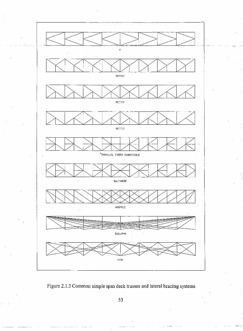
PETTIT
PETTIT
PETUT
~PARALLEL CHORD SUBDIVIDED
BAL UMORE
WHIPPLE
~BOLLMAN
FINK
Figure 2.1.3 Common simple span deck trusses and lateral bracing systems
53
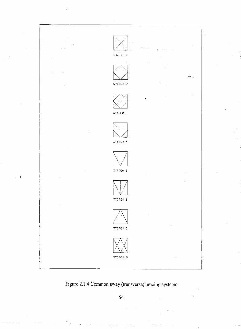
SYSTEM 1
SYSTEM 2
SYSTEM 3
SYSTEM ~
SYSTEM 5
SYSTEM 6
SYSTEM 7
SYSTEM 8
Figure 2.1.4 Common sway (transverse) bracing systems
54
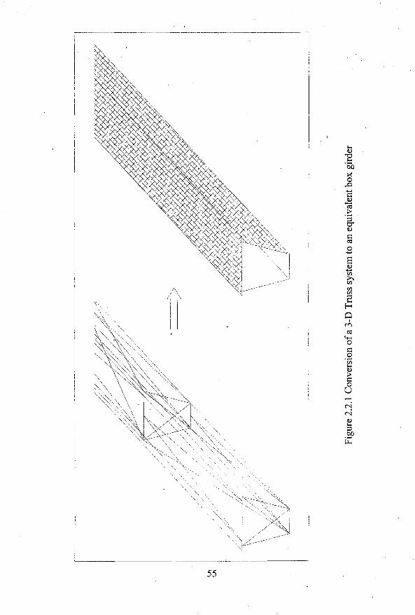
55
I
I
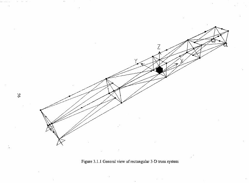
Vl0\
Figure 3.1.1 General view of rectangular 3-D truss system
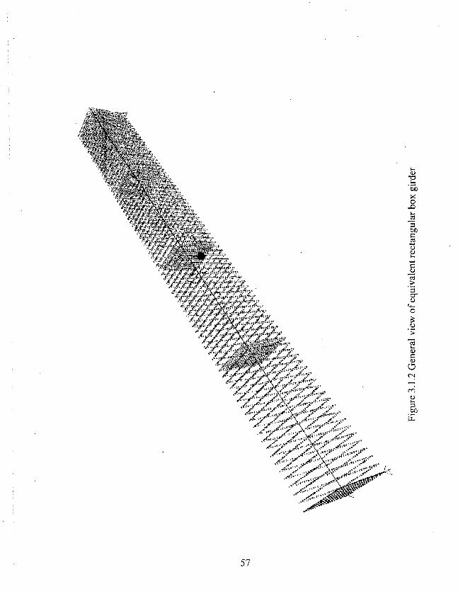
57
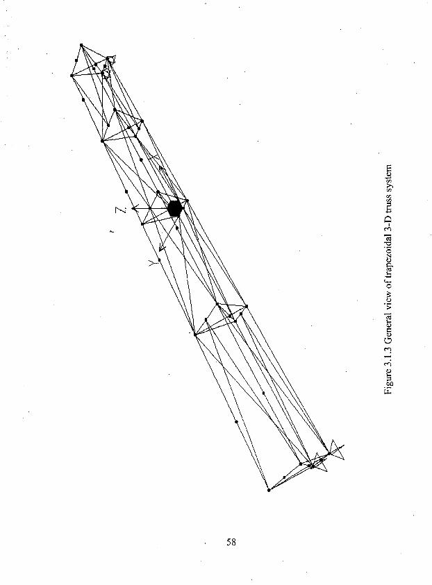
58
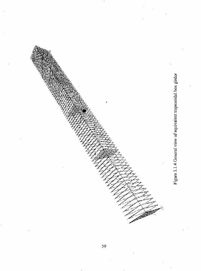
59
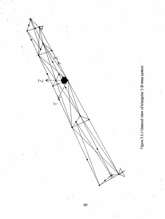
60
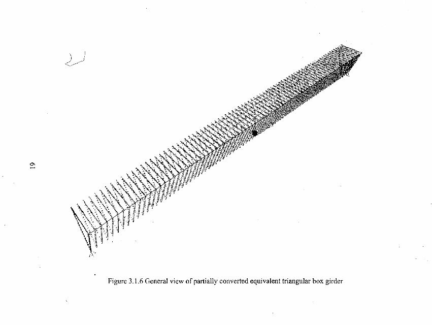
0\-..
2~)
Figure 3.1.6 General view of partially converted equivalent triangular box girder
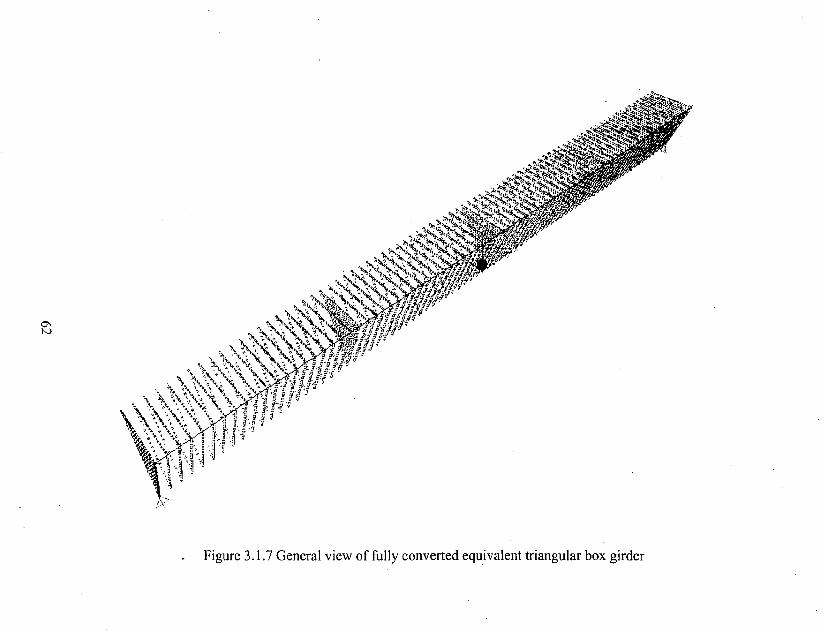
0\IV
"'(~1 ~~./.., .
• >....u'''o;.~"",.''; ...
, '" ~~~~.~;.~t~). ':<,...'ie ....."?.>...... ... •" ~ .:. 'llo••.•••~ ....
,>,.".".~""."",,'".~ ~7;~ .!,,"'~ . .. ••
" '.,,;","iL....'~ ~,,?<:-':. ~\.~. \
\. \. ~;'" ;."~ ~ \: ..~:-;:., ,'\..,.,.?.. '~\ ~~.~~
, \~,::-.'0;',~.\~~.~;;~ ~,. , \ ";,,,N:-~\\.\~'r;,,!lfh·
,
'\,~, .••••••, •• 'J.. ~'>;'• ...~.,'~.;••• ".',.F'i! k,N'j,\.:~~:::~Z~··:;t·\' ~';, -.~ 1f!f.'-{! ~
;,'. < <.' "t..>"'; i; ;r. 'I·"', ~~.<,,\: :%~" LP~g 'i
J
'0"j\~"~ '.~ ,",.\ .~ " .
/:\:-:.
Figure 3.1.7 General view of fully converted equivalent triangular box girder

1520X12ll/2 1510X12W2
y
y
1 x X /I , 6'1. '1. I
Figure3.1.8 Truss member sections of Case 1
63
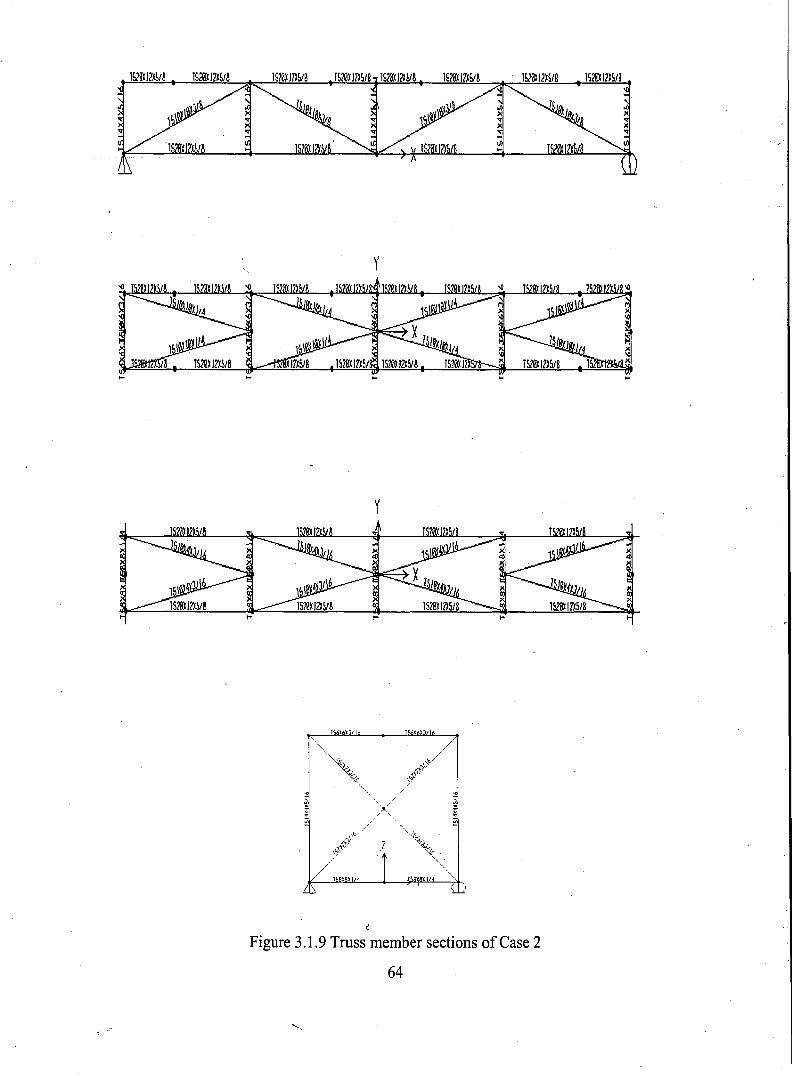
y
y
, , I1 "
~
Figure 3.1.9 Truss member sections of ease 2
64
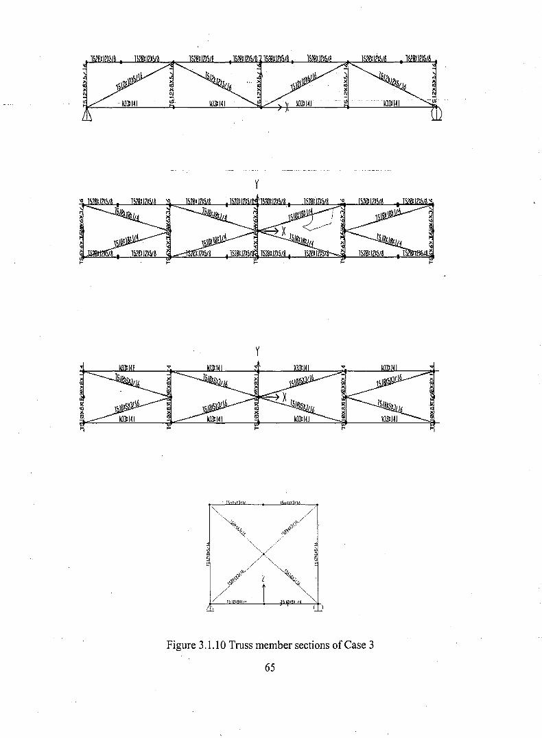
y
... ... ...
y
... ...
1 )'''t I' .. f
Figure 3.1.10 Truss member sections of Case 3
65

y
t-
y
, , I" I
,Figure 3.1.11 Truss member sections of ease 4
66
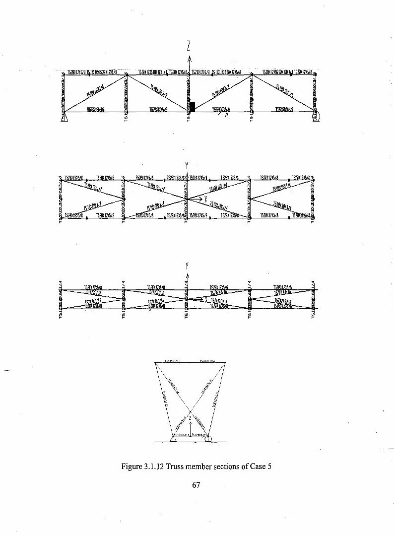
z
y
y
,.
,.
..."
l/),..
Figure 3.1.12 Truss member sections of Case 5
67
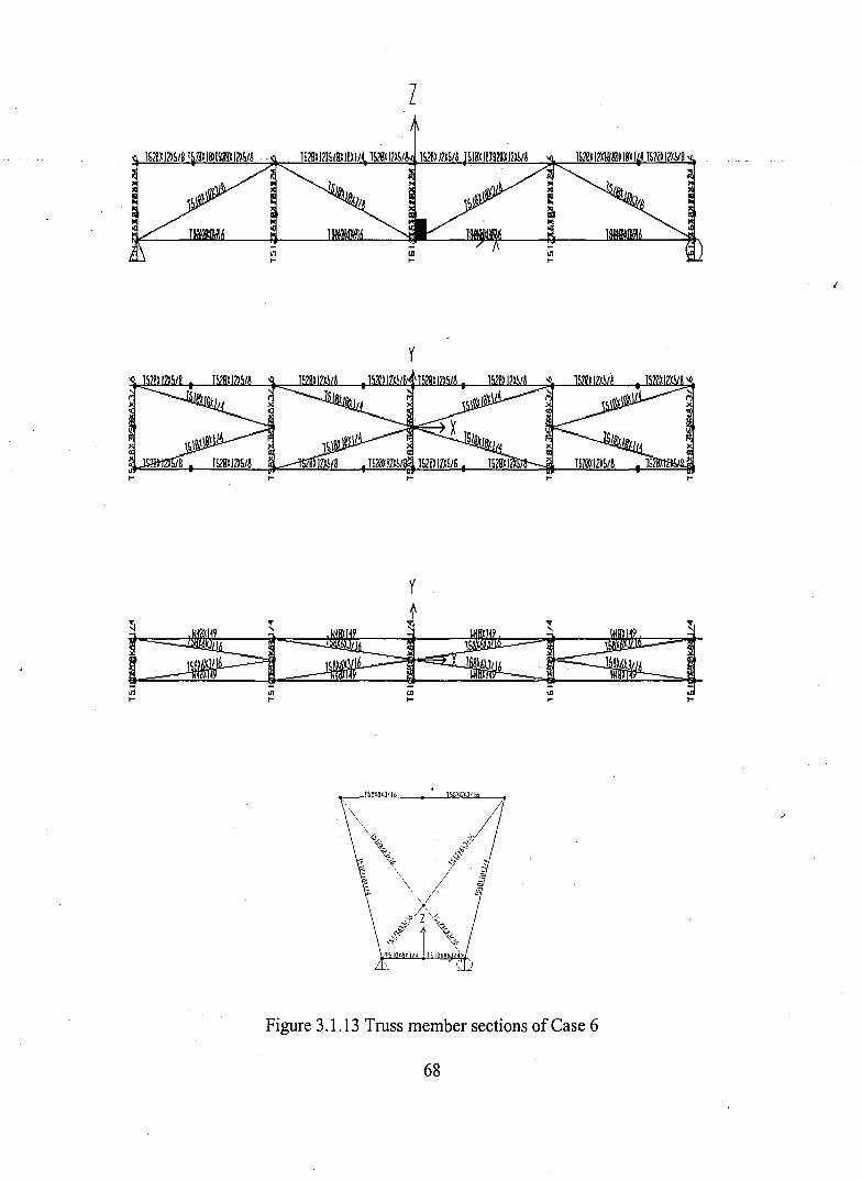
z
y
y
-IIIto-
Figure 3.1.13 Truss member sections of Case 6
68
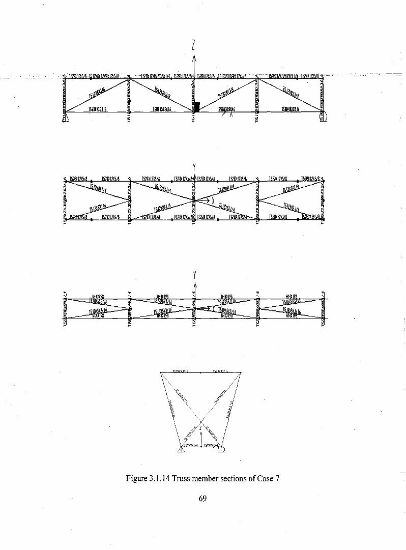
z
y
y
..."
III,.. III,..
~x X I ~ 7 f
..."
til,.. ,..
Figure 3.1.14 Truss member sections of Case 7
69
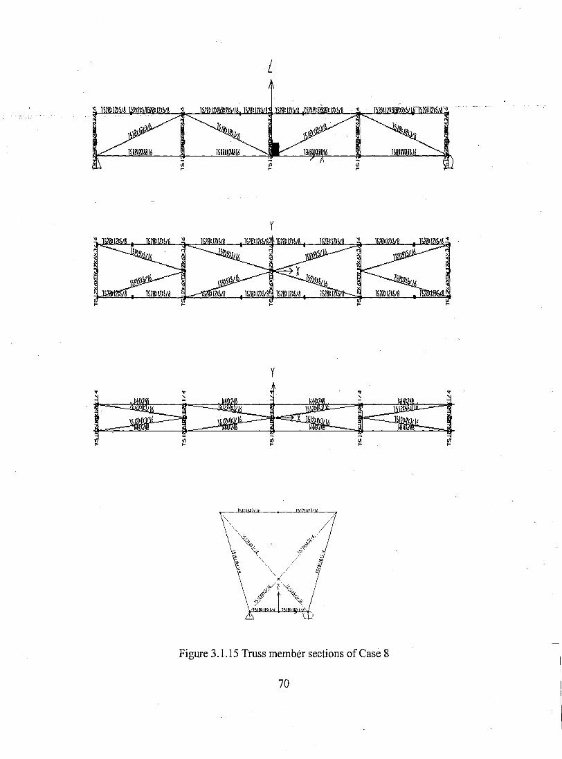
L
y
...
y
...
...,
T ~)' X I , 'f
...,
C/I... ...
Figure 3.1.15 Truss member sections of Case 8
70
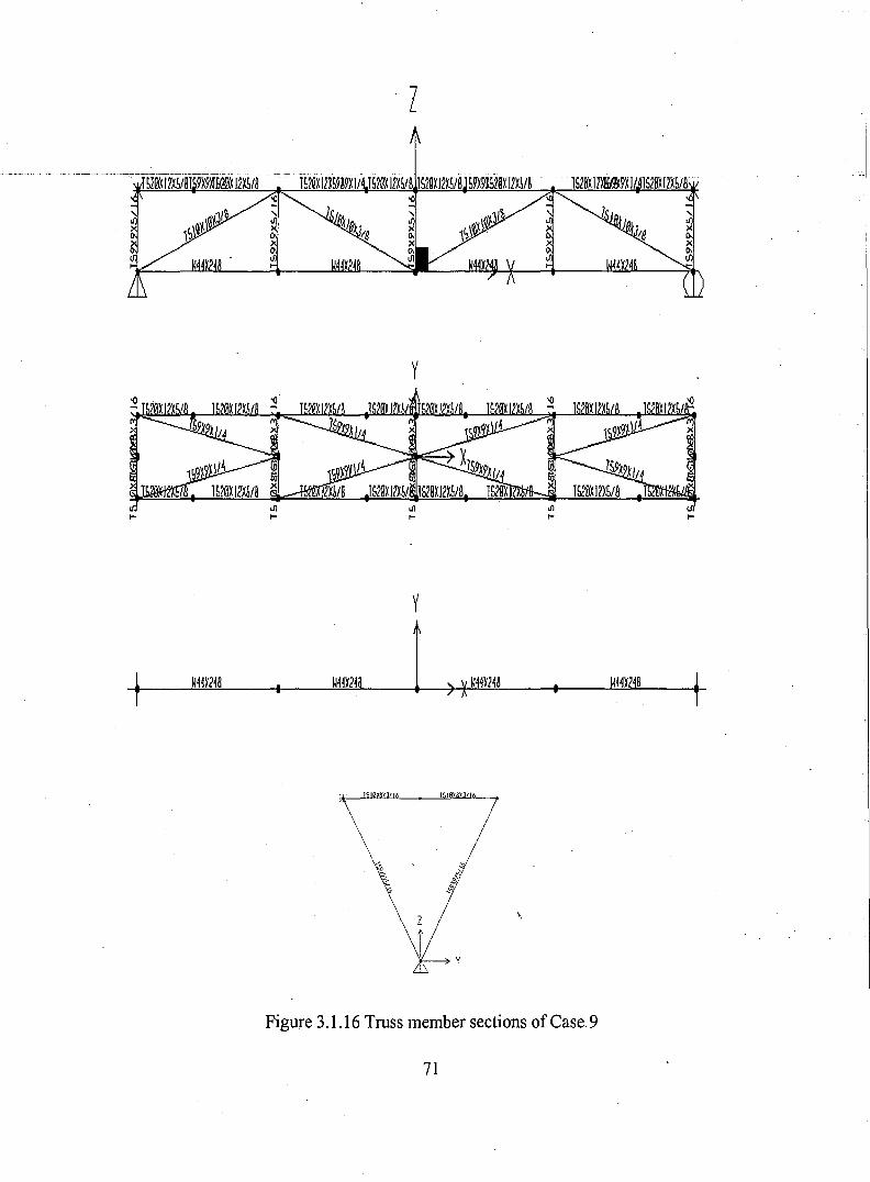
· z
y
.....n....
W44~24B
.n
....
y
W44~24A
1 0~): I 1 x X II
\
.n
....
WH~24B
Ul....
Figure 3.1.16 Truss member sections of Case 9
71
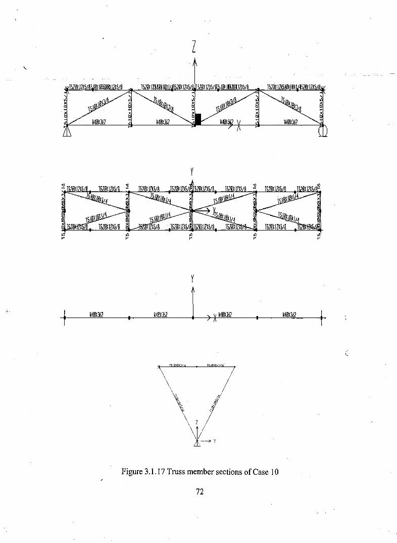
z
y
y
-1W4Bi'362 I W4B~J62 1 ) )( W40~J52 W~0~J62
~
'\"""'" "'~"'!\\~.. i/1, iJ
~ !z /
~y
Figure 3.1.17 Truss member sections of Case 10
72
c
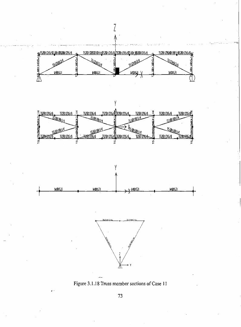
z
y
J-l/)... l/)... l/)... l/)...
y
-f U4B~5JJ U4~SJI I >XU40~531 . U40~531
~
Tspxen/16
~ .Figure 3.1.18 Truss member sections of Case 11
73
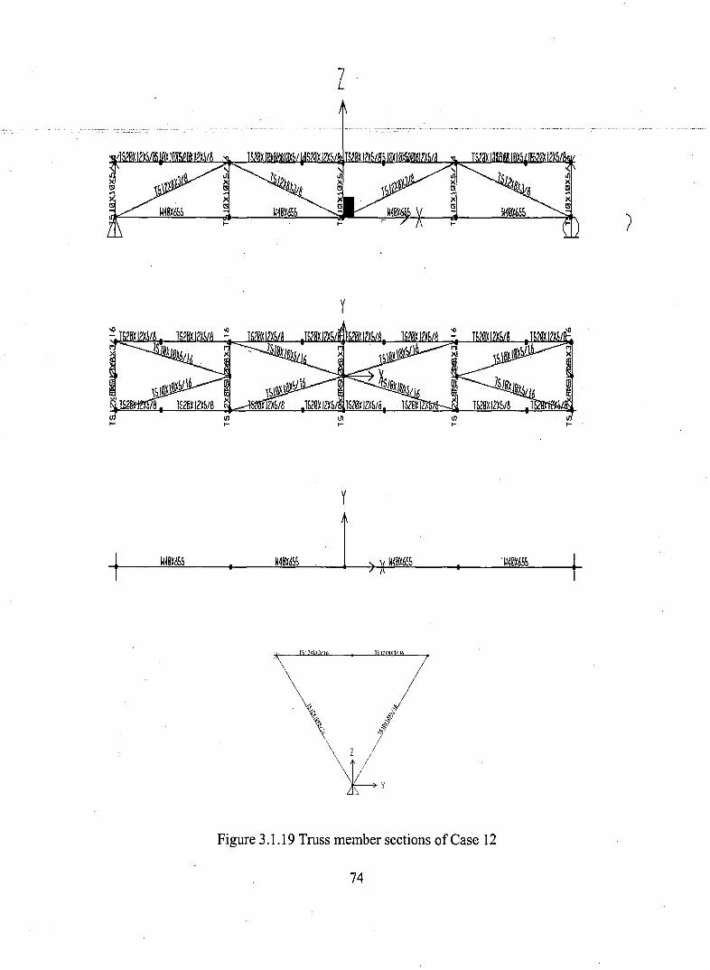
z
y
y
-1 Wj0~~ U4B~d55 1 ) )( U4B~d55 .U40~65!l t-
, / 'X):I
Figure 3.1.19 Truss member sections of ease 12
74

--.JVl
.--~
__~'ri'i<f,n<f!'r:~~_...,4tfiif/
fl,_~'-';jl'" <
....""":~-,1.1 ': i"Il,,; _-...;f!;""t! I' , . §.---.:'" ' ::' ~''-'' ~_-"f I'" .4itrfli~' i__+i" <, __",,<~,'1'" 1!Iif:~
_.,<!!'ii" . .I: _,,~iI"· .,."'Il,i",...."" __"?iiI" <C "".,., •
•<It<"~1"~~~~""!J~'t:~~__,,!,~~~i"'~~~~~;"!ff"i"""'"~.~~V,:::il, ~...~rJC\C" ~" \:. .,..4if:;!';".'""'~ ." ,....~$~ ';'..~ /r.__...~"'ii i"
"",*"II'1f"f,.! ',"" ..~.",...'~' '
• .,,~~~~"'i!;:"" ~'~~,~~~~" ".·ifpr
~..."I"" ...~ill"·' ..,.."l,J:'..._,""" . ~_." ,<' -.,~'".....'"!!i< """, ~..."",'il'''''''''' '/ "".,-.< '."'il;!l,<1"" ~'11;"'" ""II'>m ...,~~.!,,,,~,, ~.~"', ~" ..... ,
..~ ~.~V" .If{'jf"!'~ #,,;.,. . •..~1S':fi%..,"'llf,'Jt}!" Alp"~_,~_""",,.,. ~..,'f!J'"\~:f~ ....J!'.~tr'9'f;~,F
.-;:-: ~'.~''!J.0,) .,'
/~;~t'2i;"
Figure 3.2.1 3-D view offrames of partially converted rectangular box girder
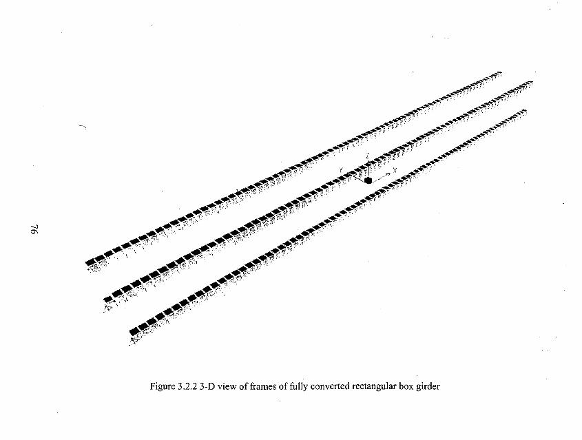
-,
~0'1
_~~~0........~~,:'
~--~~~~~,-,,?~::::~~::"".V --' ~...~.,~e'" Z _#i"" ••••.~.','t\... . f--":' tif " .' ..,:'..,." ( -<oj""" .
~.4!!'i ~ f ~ ;, ~#<fI>;~.~. ~ " -~,...~'i·; ~ ,.,- -~;"
~-.;" f' {'" _ ..~~".-....~.'''' ',L ' . ~.-.; ,,' u· •
"'~f''1'" _~!1'___..~!i1." ~.,.. ,.,.," c·~~;;,j'~' • . ".,~<J'--..., j!;! i···.. ".,~ ... ,,'; ,
~- ~-"" -.,.,~- . ~-~" . ~~.~_'" , ~~ '," ~4'fi'". ,._ . M"'".<', ~...."' " ~,.:--.~ ,," \ .~;it.' ,"
,-.;.--.~, . ' '. __'4!i,~1, '...-.:;;,'." ~~;.--.~ "'il'i·\ ........",.-oOlI;.~,C":~ '\ ~..~S'<''''
<tf/!;;~,"'" ......~ .•-""'., •. ,\ __~ C"i't' ..-....~.N·',.··
. ...-4ft.,~';~"?>\
..JIIt:'.......---,!\\.~~.'.' •
• ~~li'i5!fi~,~lr;:\. '
Figure 3.2.2 3-D view of frames of fully converted rectangular box girder
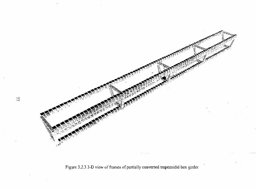
'-l'-l
~~~1-;'ifrq,..
~~~~~~~~-;~~~~~i~ff};",,#"'''' ,,'r~ "".,~Hli!'I'" ."""",..~~~~i'~~,:~,._;~;~~~"tffi'"
_.,<IIi""- -,!if>, ~..1i,~"'" . iifl'" C'
_ ...... ~'''. \>.,... ,",_~.••r," """,-'~.~;.,~:!?;:., . ,,;:. "'\~"""~ .,,-!Ii ".,.'~ iQ.1Ii "." .--....-: ,," ' ._"",$. F.... ",' ,..~~r,,· ,,' ~" '*,~;"?:.,." '~ll.*"t~t"· H"
......•r.:' . 1!II1!".,.1liJ".·' ' ,.,..<tfIi.' .'~fI4:"~' .,' .4,'J.t~I".","~~"".
~;(., ••"j111:'p'i!:,~'''· ~~.~ . ..-.....4.~~~"';~'~"~." . -.,<tf1?,..,~,\l\~'.?;: ~~~\n/",.,;~~l!ll;:.," ~"'f!; ....
~~'.!Ih":{;,(>!" .<tIJ,"~~'" .;¢1"""\."""-" .,A:':'~\'·· <tf/Jf;..'%f;i\'~ ..." ."1 ,•. ,\ ~~.,w',\
J.,:');tc,~~""
Figure 3,2,3 3-D view offrames of partially converted trapezoidal box girder
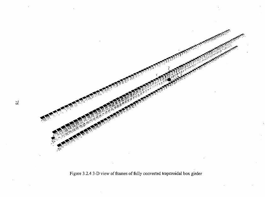
-..l00
~if1:_""'""i~""__.,~11Jj,·, ---...,~
_-'-:~!"'f' ' . __...,.,-,,', I
- ,.,• .,-4Iij,(' ,...__""j'~'~~";' ....._.d!;'__-..--"~'f1.,, _._......rU~I,~i'i -..4';...,-,.,.""f'!'" . ..""'p'(;,,, ,. ~.. .
._~~.'f\ -";'r""'" .....$"..A'" . "".-"" ,:.,." ...""'.,'
",,_d' - 4'-""./ ....,."t-.-....~,_"., L _ .... (I<f~,<'(t:' _#I.'"~..~_,; C1."'j(;~*~ ~~1' -~"'_.~<tf' y ~ r1.·'d' ~•.,.".,
","",- ,. ' ,,,'" '" ~'.....-<f.'i;-" . --.,~...,,1~..""-..,-..:;; ,-' '" ".,-"" ,< ,\,'" ";,,, ./~_'41fi"''-
_,*4J4!ii..,f . ",.4~~':·"" ...,."....,'...... ':",., . ~~~",' , .,.' "~..ttf"-",, ~~I""-' ,-',.,-" ., -..,.,.~.' ,-- "",,""y. .. ~.,.",,-" ~ •. ' "~",,~~""" _~""'''.'_ _-<ft'ti'~~, , ~~~.,",A ... ~...."~."" .., ' ~,"''''~..f''- .-.<.'"",,-l!" ' ~"-\."..:" •...,. ~.4if'i,~'
""""," ......~ ".l'!'~!.i'" ~" " -!/ff!;.--,,",,1
c
'........~~,0.,. :t4'f'!. " ~"'.''if!._~, ~"~,, ~~ ~~: .'J ~f!..f'~':.'.' ~~'~'<J!'I....~,.,- ..~~.,
_",; _", '.', 'f"., ': ,,,,'" ~ \\. ' ~«",i" .' \
...,lIl, """" ~~"",,,~,'. _'" .t',' ~~'!'l~""'".' \ ~.-.r<"- ,,.:;:> ........,.,""!J?;,Wi," "~\'.~\~
;'9'
Figure 3.2.4 3-D view offrames of fully converted trapezoidal box girder

-.,J\0
~.1\'~...~.~~/".~ '''~ """i'"
..~~"ij'J,~e.
__. ~..~.•......:f:~~1l!.P~ .'_ /I11J 'J;-~f ..:':~.\.':'<"4., I
f1!. ~~.t;'~·\ .~~~~.. , '
..:-?t::'";~-
..'q
.~.~ ...7~1'M':~.<o!,~~
.,~::>~r:
~_..---rfj'_4!'<~jftf{f. iP"'1i.ii7j-·
. __-.,,,f(l ,.. '~"~~, ~..;!J"j""')J}i" r::::~4';;!!li
__-.-.""fri;~!"!' _4i':!"-tl (lfJ
',..""':,--C~p!' ,'.Jj,I(rrJ'l"~ i1Hf";.~'
__.-~p, . t~'l!®ffl--"'i1f(L~.~t;j;"f~.... ,,,~,: . ~'" _;0,;:, J ',,"'''''It/T' 1·'",_~,,/!."l: !Ii._..... ~' ....,'l.,."~.';,!,~;l) ~." ~ -~ drF",~!'"11IfP' ;.,-"I!\"'" ~~.d~.J!~.'t{"l!l, ~ iL;"J.,.+~
......~ir~~.. ~..,.,ofI(:~.-.' :(.r;··!"~"""_ ..... jf",,"'~...,~f~li'i' ,~...,
.~~.'~''':~'''''''~'.-"~~l~'~·"n~,f.-l~~t~:'''''~_, "..,.....,.,« ~,..."'" ~i• .'d"""~" * i!~~l" "'''!'Il~r ."~!;.:;..""~r~"'1. '1!'-; ~1}~~i';i~' ij;.J,..·~
~...,"1(t1J. . "'),~ , ,;, )iV"".., , ';)'1 "...,' .,,,~~ ....
~""';.'.iii.;j!·~~·"·.""".~'. ,..' .~,~ ...~i:l\ji'd'!\b~t~?'"~~"i;';~ ~r:;..~
~....~#",-JJ!}>#"~
Figure 3.2.5 3-D view of frames of partially converted triangular box girder
r
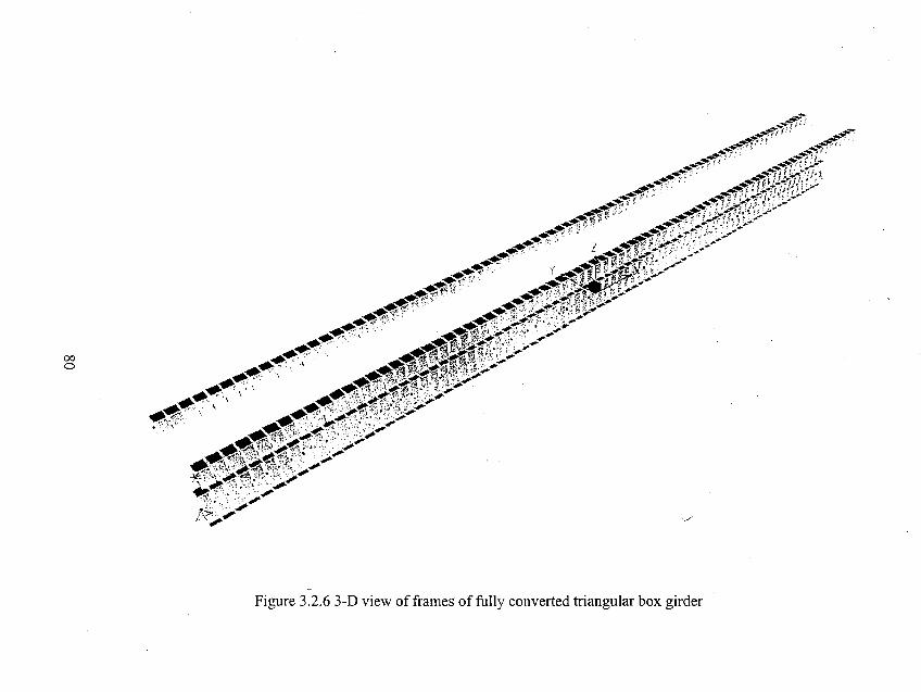
>/
00o
_...,--r.-;-;.':"ii:_--~;'i'·· ~...,-:
_...,~~~"""j<' .' _-""i:'~."__--....-..." . ' . __-,-,"'";jffL.
__~., _",-'f!5£.:-~:-;'";'...-• ..,--'fr,' _..~-,,!Pf~~;''';j!)'irt
_,...~~",~"" .,_ ,.;., '~'";"'1 ,,'.' .1','._ \ ~ >" >" ".'_ ':. : :.;,,1" 10"'" :...",~._.",' , ~_.. ,_1 " ...#~,;,.\ './~_...,. " __-; , :_.......1·'."1"·".-'
_ ....... " _ __-~ _;, 'f" ,; .;' ~ , :;---
,.,..~ L ,.,...-,p' ji' ~...""., ...--
-«'"' ,. -",,,, ."'" / ..-~_,,,,,, , ....... ill1li'~'''"'--' ,. --,.,,,,., f, ' --"'; ,.'$Id' ' . /'",<Of.<' «__II~ -'.',...'~~ "f' ,;< • -:+...' <1 it :r~ ~.!; .. i.' .,.;;;:7...-..,~ '" " ..,,~ ".' ,~",t:.,~jt ,,, ~ _1~;,.- . . .-"" ~-,-""'" ~,..' . , .~",~/"c:.,e'!-V~••, . ~~'''C#'··'··~~
......~., . \ ......~~il'li)'i.:;---:;· • _ .....",_. . M"'ll· ".;,:;" "." ..-.~.#] .' ~..lIjl!l..n .W,'· /#__ ". ' ' _,,',i!I"'--"""'" '''-'~...". " ~4"""".". d"l1f ",.;.~."." . ~_ """, 'A':."~'\"/.'" ---' ,..-......".,",.#.......~~ • ',,' <1":~;'" ".' " ..,.-
........~ ., ' ,'.#:"'''''''''(''~')'' . ::;.""""'~"~" .' ~., ~,:i " .:, ," ,;;""
........ ',f!'a ~",; ....~~ ,:--.' , o~.,........'Y":'\""''- ,<' ,\ ~, '. ,.,,--
.........-.:;i"::'~~\.,.:,\ ....~ ""', ." ..'~. ,\, .."~~.~-,,. ;--¥:'\'''.' '2~'";'·,:'-';.· .;.\ fiJ!:.-iI!'f."'.ift\,,-.~,;·, '';';~ ,"'. '._ 0,. ..;..;
,,'i'\ ..•...... s,""i?";"
Figure 3,2.6 3-D view of frames of fully converted triangular box girder
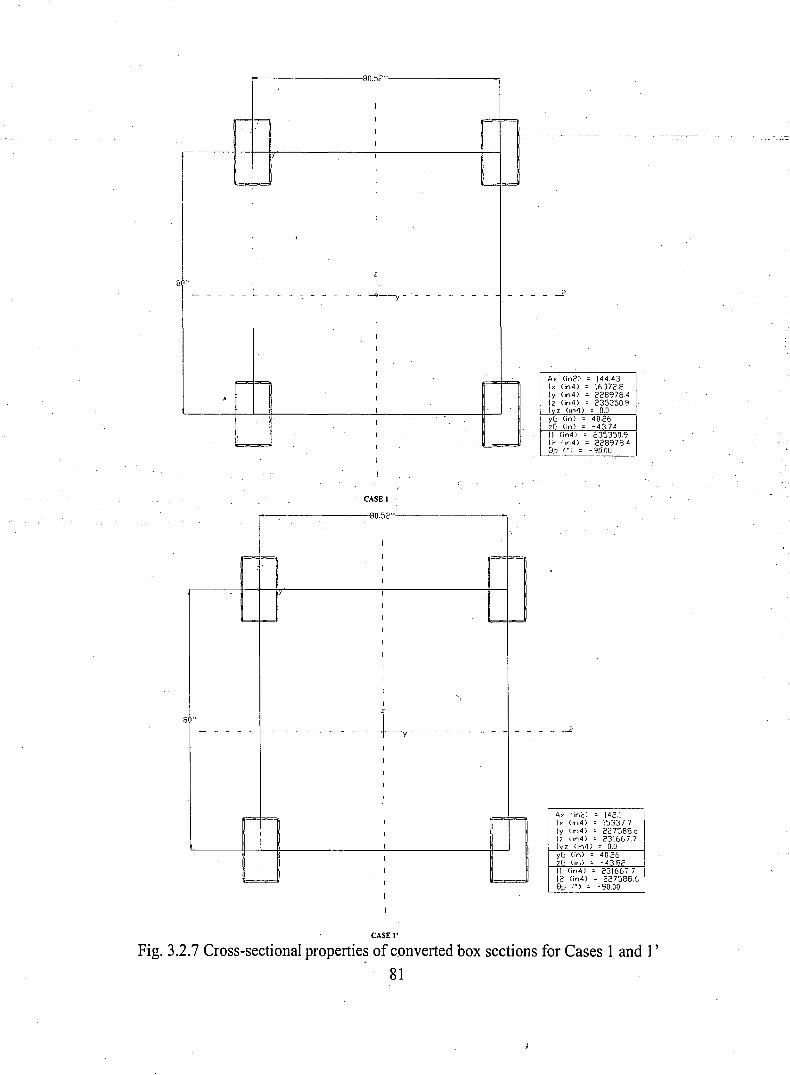
r-----------'80.~2"·---------__.
8 "
Ax' (in2) 144.43Ix (;n4) 16372.8Iv (;n4) 2289784Iz Gn4) 235350.9Ivz (;";4) ; 0.0vG Gn) ; 40.26zG <in) ;:: -43.74II Gn4) ; 235350.912 (,n4) ; .228978481' (.) = -96.t)[l
CASE 1
-- 80.52"
I
f='" = I = i==I
I
I
I
i=..,1=-= 1 "=--- 1=-=1
I
I
I
I
1
1')
8 "
~~-- - - - - - - - - - - - - - - - - - - - - - - -
1
I
I
1
1
I
i== ~=I 1 ~1=
I I I I1
I 1
=1I
I '=
__ -2
Ax. (in2) 142.1 IIx On4) 153377 IIv (in4) 227588c. IIz <in4) 231667.7 IIvz (In4) = 0.0vG (in) = 4026zG (in;' ; -43.82II <in4) - 231667.712 On4) ; 227588.681' (.) = -90.00
CASE I'
Fig. 3.2.7 Cross-sectional propertie~ of c_onverted box sections for Cases 1 and 1'81
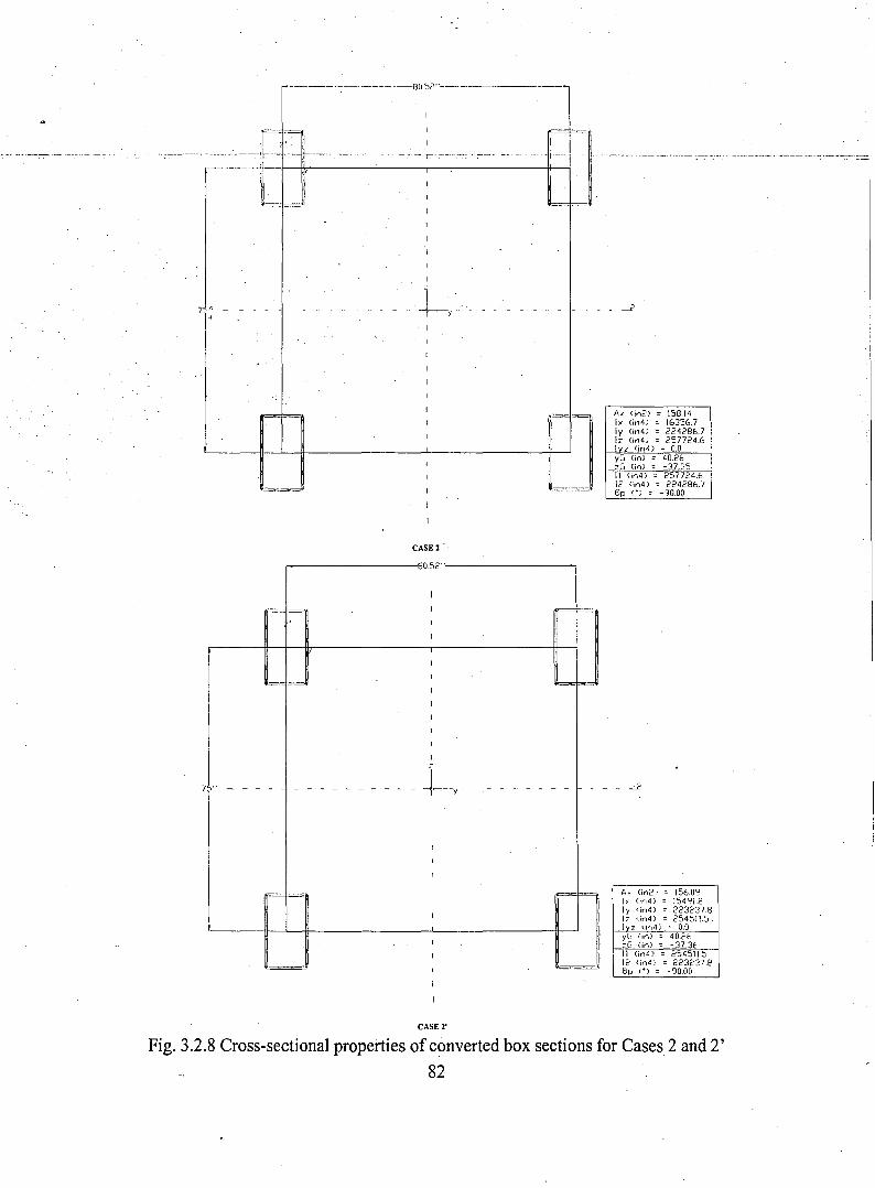
----:------,--------·--f)(J,':Jr.)·'---·--------
--- -- =-- -~ f-+-tt~.,----.-.----..--~------:,-----,r·--..----. -----.-. ----tt---i~~. --._---. -----------._--_._----.,,-- ----.------- . ---_.---- ---- -- -----,--::=:
7"'" -
l'
I
==
CASE 2 .
,=='
___ ...2
A> (;'02) = 158.14I> (;n4) = 16356.7Iy (;n4) = 224286.7Iz (;n4) = 257724.6I z (in4) ;; 0.0yG (;n) - 40.26ZCI (in) ;; -37.3511 (;'04) " 257724.612 (;n4) = 224286.78p (.) = -90.00
,-------------8052"-------------,
I
J,
=~,=-~'
I==iI I
'=1=..-'
--_._-------~
CASE 2'
A) (in2) :. 156.09I>' (in4) ;; 154':11,2Iy (;n4) = 223237.8I:: (in4) ;; 2:,4511.5Ivz ~jrI4) :: O.DyG (in) :. 40.2f.:G (;n) = - 37.3E11 (;n4) - 254511.512 (;n4) = 223237.~
EJp (.) = -90.00
Fig. 3.2.8 Cross-sectional properties of converted box sections for Cases 2 and 2'82
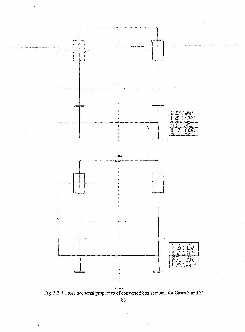
--------------80,52"--------------,
____________ -2
=A, On2) ; 166.28I, (in4) ; 11690Iy (;n4) ; 217092.4lz (;n4) ; 269559.1Ivz (;n4) ; 0.0
7 '"
CASE 3
,..----------80.52"-----
\yG (in) ; 40.26zG <in) ;: - 36.641\ (in4) ; 269559112 'in4)'; 217092.40p (') ; -90.0fJ
__ -2
A, (,n2) ; 164.37I:... (il".4) = 10926.5Iy (in4) ; 216218912 (,,,4) ; 2665561 = (;n4) ; 0.0yG (in) ;: 40.26zG (tn) ;: - 36.6811 (in4) - 26655812 (;n4) ; 216218.90p (') ; -90.00
CASE 3'
Fig. 3.2.9 Cross-sectional properties of converted box sections for Cases 3 and 3'83
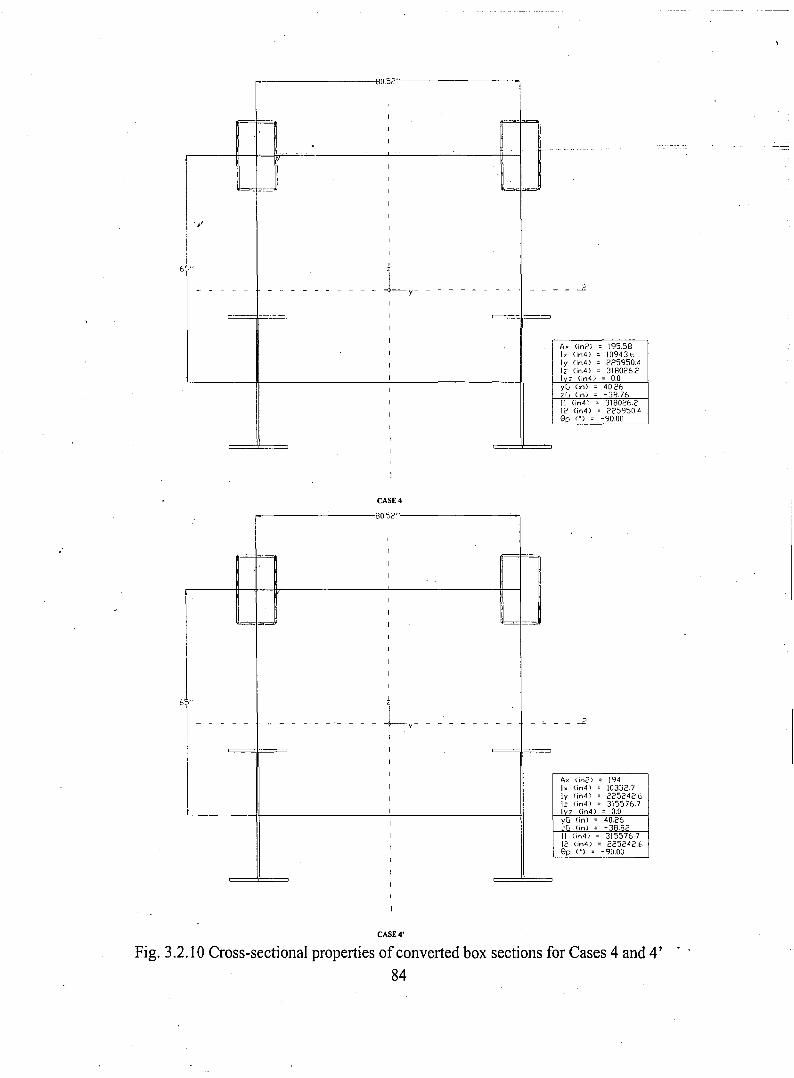
,..----------180.52"------------,II
=='1
I~~--~J
6·"
_ -..2
A. (in2) = 195.58I>' (in4) = 10943.bIy (in4) = 225950.4Iz (in4) = 318026.2I z (in4) ; 0.0yG (in) = 40.26zG (in) ; -38.76II (in4) = 318026.212 (in4) = 22595040p (.) = -90.00
CASE 4
8052"
i
[I I l 11II
j II
I IJI ~
I
I
I
I
I
'1
" Ly -- - - - - - - - - - -- '- - - - - - - - - - - - - ~
I
I ~ --- I ,-r1
I
I
1
I
t I
I
I
I
I
I
__ -..2
A.". (in2) 194I. (in4) 10332.7Iy Cin4) 225242.6I: (in4) 315576.7I z (in4) = 0.0yG (in) = 40.26:G (in) = -38.8211 (in4;' = 315576.712 tin4) = 22524260p (.) = -90.00
CASE 4'
Fig. 3.2.10 Cross-sectional properties of converted box sections for Cases 4 and 4'84
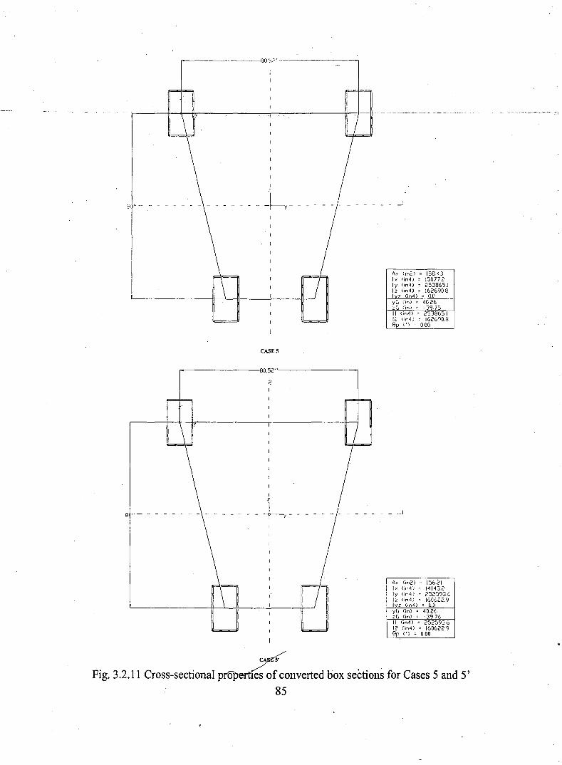
,..-----------80~? ..-----------_,
yG <in) = 40.26zG <in) ;: - 39. 75II (in4) = 253865.1Ii.' (in4) = 162690.8Gp (') = 0.00
A,. (in2) = 158.4 3Ix (in4) =- 15077.2Iy (in4) = 253865.1Iz (in4) = 162690.8Ivz (in4) = 0.0
8 '" - - - - - - - - - - - - - - --
CASES
r-----------80.52".----------,
2I
yG (in) = 40.26zG (in) = - 39.76II (in4) = 252593612 (in4) = 160622.9Gp (') = 0.00
A, (in2) = 156.21Ix (jn4) = 14143.2Iy (in4) = 252593.6Iz (in4) = 1606225;1I z (in4) = 0.0
I
--t-r-8 ,,- - - - - - - - - - - - - -
CA 5'
Fig. 3.2.11 Cross-sectional p 0 les of converted box sections for Cases 5 and 5'85
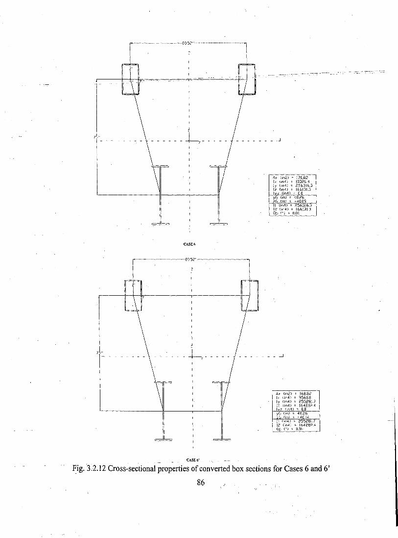
---~ - ------80~?" -------------- - ----l
--_. ~-~--,-------- _."
_______ --l
A, Cin2) 170,82I, (jn4J 10326,4Iy (in4) 256316.3Iz <in4) 166131.3Ivz (in4) = 0,0yG (in) - 40.26zG (in) = -40,0911 (jn4) = 256316.312 (in4) = 166131-30p (') = 0.00
CASE 6
_ _ _ _ _ _ _--l
---------8052"'---------
A~ (in2) 168.82I, (in4) 9560.8Iy (;n4) 25528L712 (in4) 164282.4Ivz (,n4) = 0.0
7 "
y(' (in) = 40,26zG (in) :: -40.14
C~SE6'
~ig. '3.2.12 Cross-sectional properties of converted box sections for Cases 6 and 6'
86

·····----·--80.':,2"----------
IIJ
1---~----------!t-----'-----__l1
CASE 7
,----------180.52"----------,
2I
Ax (in2) 198.82I ... (in4~ 9775.5Iy (in4) 265833.4Iz (in4) 177462.4I z (in4) 0 0.0yG (in) - 40.26zG (in) = -42.08II (in4) = 265833.41<' (in4) = 17746<'.4Elp (') = 0.00
A." (in2) ;: 196.79I, Cin4) = 8540.5Iy Cin4) = 233478.9Iz (in4) ;: 175577.3
~(in4);: 0.0yG l.jr'l) ::; 40.26zG (in) ::; -39.16
CASE 7'
I I <in'1} - 233478.912 C,n4) = 175577.3Elp C') = 0.00
Fig. 3.2.13 Cross-sectional properties ofconverted box sections for Cases 7 and 7'
87
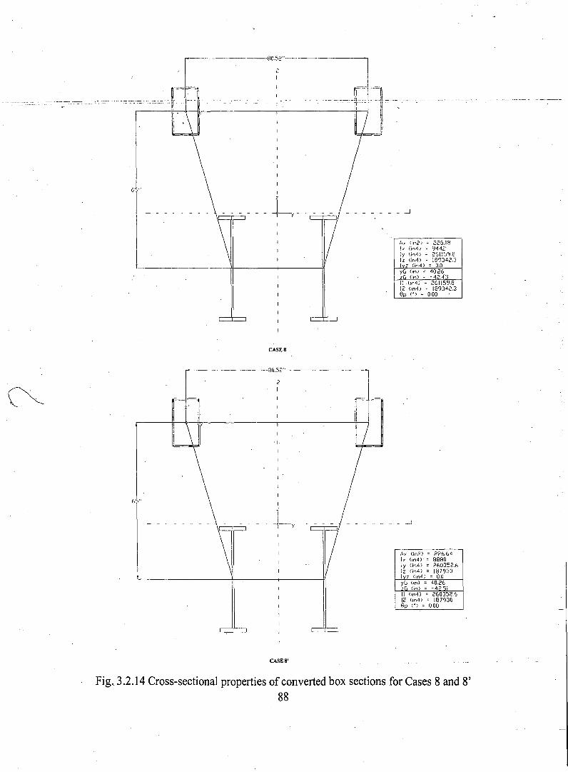
6,"
L--------IJ------+-----+1
- - - -I
r" (in2) 228,18Iy (in4) 944<:'Iy (in4j 2611598Iz (jr,4) 189342,3Ivz (in4) = 0.0yG (in) = 40.26zr, (in) = -42,43II (i~4) = 261159,812 (in4) = 189342.38p (') = 000
CASES
------ -------80.:,2"----------
--------_-1
A> (in2) 226,64Iy (jn4) 8880Iy (1~4) 260352.6Iz (in4) 1879301 (in4) = 0.0yG (in) = 40,26z[J (in) = -42.51II (in4) = 260352.612 (jn4j = 1879308p (') = 0.00
'1.
2I
CASES'
Fig._ 3.2.14 Cross-sectional properties of converted box sections for Cases 8 and 8'88
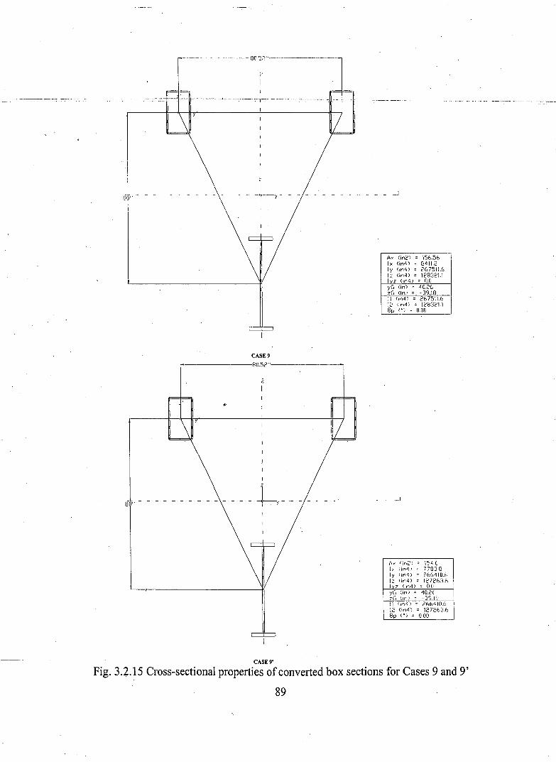
- ·_·_--~-·--80,S?·'-·_··----------
Ax (in2) 156.56Ix (in4) 8411.2Iy (in4) 267511.6Iz (jn4) 128321.1Ivz (in4) = 0.0yG (in) = 40.26zG (in) = - 39.1811 .(,n4) = 267511.612 <in4) = 128321.1
~~'i ~ 000
CASE 9
r"--------:80.52"'---------,
2I
- - - - - - - - - - - - - -8 " -h- ____________ -1
Ax (in2) 154.10 II, (in4' 77838Iy (in4) 266410.tI: lin4) 127263.6lvz (in4) :: o.n ;yG (in) = 40.2f !zG (In> = -39.17' III l,n4) - 266410612 (in4,) = 12i263.6 I0p (') = 0.00
CASE 9'
Fig. 3.2.15 Cross-sectional properties ofconverted box sections for Cases 9 and 9'
89
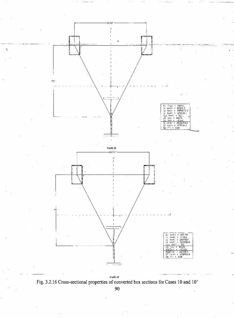
r---------J8052"'------------,
2I
yIi
~._;-
A, (in2) 189.51I, <it14) 8284.7Iy <i(4) 285873.312 (in4) 129134.1Ivz Ci(4) = 0.0yG (in) = 40.26zG (in) = -43.41II (in4) = 285873.312 (jn4) = 129134.18p C·) = 000
CASE 10
,..---------80.52"------------,
2I
_ _ _ _ _ _ ._ _ _ _ _ _ -l~l-),-
I
J.
CASE 10' .
A> (in2) 187.78Ix (in4i 7710.6Iy (in4i· 28490712 (in4i 128200.8Iv 2 (in4) = 0.0
Fig. 3.2.16 Cross-sectional properties of converted box sections for Cases 10 and 10'90
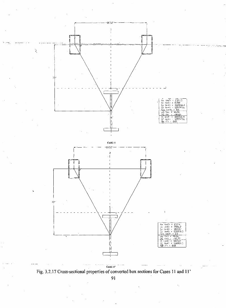
--------8o.:>2"---------
• __._ - _.L 'jl~~~~--~I·-------_··
7 "
I'
___________ ..J
Ax (inc) 239131> (in4) . 8058Iy (in4) 302856.412 (in4) 129749.6Ivz tin4; = 0.0yG (in) = 40.26zG (in) ~ -46.69II (in4) = 302856412 (in4) = 129749.60p (.) = 0.00
CASE 11
r---------~80S2"--------__,
2
I
7 "
____________ ..J
Ax (in2) 237.6Ix (;n4) 7586.2Iy (in4) 3019071z (in4) 128919.3Iv: (in4) = 0,0yG (in) - 40.26zG (in~ = -46.7711 (in4' = 30190712 (in4) = 128919.30~ (.) = 0.00
CASE 11'
Fig. 3.2.17 Cross-sectional properties of converted box sections for Cases 11 and 11 '91
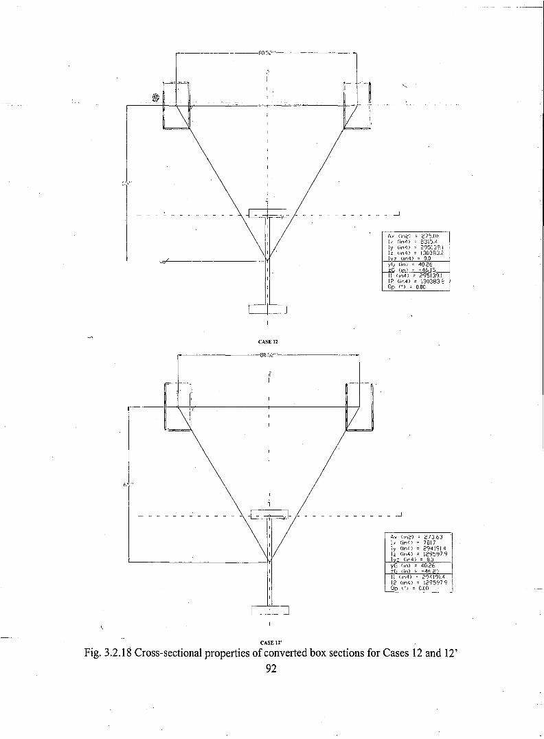
---------------80.52"----------
",-I
Eo 1"
....../
CASE 12
,..---------~8[).S2"---------_,
___ ----.l
A,' (in2) 275.08I. (jn·1) 8315.4Iy (in4) 295139.1Iz (in4) 130383.2Ivz (jn4) = 0.0yG (in) = 40.26zG (in) = -46.1511 (in4) = 295139112 (in4) = 130383.20p (') = 0.00
'---'=---=rt;==l£-r- - - - - - - - - - - - - ----.l
A. (in2) 273.631> (jn4) 7817Iy (in4) 294191.4Iz (in4) 1295979I z (in4) = 0.0yG (in) = 40_26zG (in) = -46.23II (in4) = 294191.412 (in4) = 12959790p ") = 0_00
CASE \2'
Fig. 3.2.18 Cross-sectional properties of converted box sections for Cases 12 and 12'92
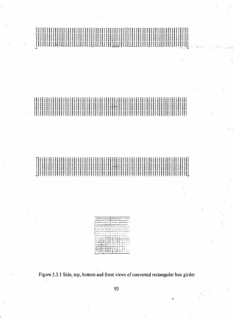
!111111111111111111 !I! 111111 !11111111111111 !1111 fI!11111111111111111111111111! II !
... ·111 111.1 111mlll.lll. IJ II 111111 llJllll1 Illllill 1.1 111111111 1111111111.11111.1.11111.1.111
i'i iii iii iii iii 1iii iii iii iii iii iii iii iii 1'1 Ii1i' iii iii iii Ii1iii iii iii 1iIi iii iii iii i111111111111111111111111111111111111111 HtH 111111111111111111111111111111111.11
. 11111111111111111111111111111111111111111111111111111111111111111I111111111111111••••••••••••••••••••••••••••••••••••• t ••••••••••••••••••••••••••••••••••••••• t •••
TI iii iii iii1ill iii iii iii iii iii iii iii ii iiI iii iii iii iii iii iii iii iii iii iii iii iii iin1111111111111111111111111111111111.111111 Htl: I1I11111I11I1II1111I111I1111111I11111I11111111111I11111I11111I11111111I111I111111111111111I111111111111111111111111111I········t t •••••••••••••• t •• t .••••••••••• ~t • •••••••••••••••••••••••••· •••T
;7 i ~ .____ ~.__~_•••• _ ••_~.__4"·
I-·d ~~--~-------....--t---.~-~- ..-~-_.-\-- ---.- ..--._.--.. -.~ ".'.
. , .._---------_.._--_.._-.,.-_.f------···- .--...;.------.....--.• --~_ .....,I·:·:::::~:·:.::: :-: :-- :-:::: ..
~1·=~iJ~~:t4~irlJi~~~~:··f~ -1~~;J:it:;~·;+: ••'I -- ~_,_LL·1-·H-,·,····,
Figure 3,3,1 Side, top, bottom and front views of converted rectangular box girder
93
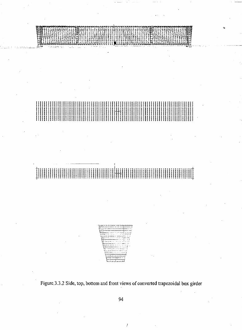
, ,.'
11111111 !I!11I111111I1111 !I! !I!I!I111 !II j II !I!I!1111111 !1111111111111111111 !11111 '
11111111!1!11111111111111!11!111!!III!11 HH111!lllllllllllllllllllllllllll!llll!I1111111111111111111I11111111111111111111111111111111I1111111111111111I1111111111 .
i
..L•••••••••••••••••••••••••••••••••••••••~•••••••••••••••••••••••••••••••••••••...L
!II !I! I!III! I!II !!!I!!I!III! !III! !!!I!II ...H!I!!I!!!IIII !!!!!!I!!I!I! !III! II !IU
~~~:~~-:#t1:J\..i ....... _......__.._._ .-..----.~ .. ~ •. ;,
·~~~~~:~~.·~:-.:~~:·:~:··.:-1: ':-;'!6-...........----- ..-•. ~., "-'-' .. ,\-~ ._ .•. ,- _ .~.L-=-":-:----::::: : :,: ' .'\~_ ..._.~.... 1· .... _· ••..',,'.' I : ..\---_.-.- ....._.;-;.
. ,\j;"., ,-;.'
FigureJ.3.2 Side, top, bottom and front views of converted trapezoidal box girder
94
J
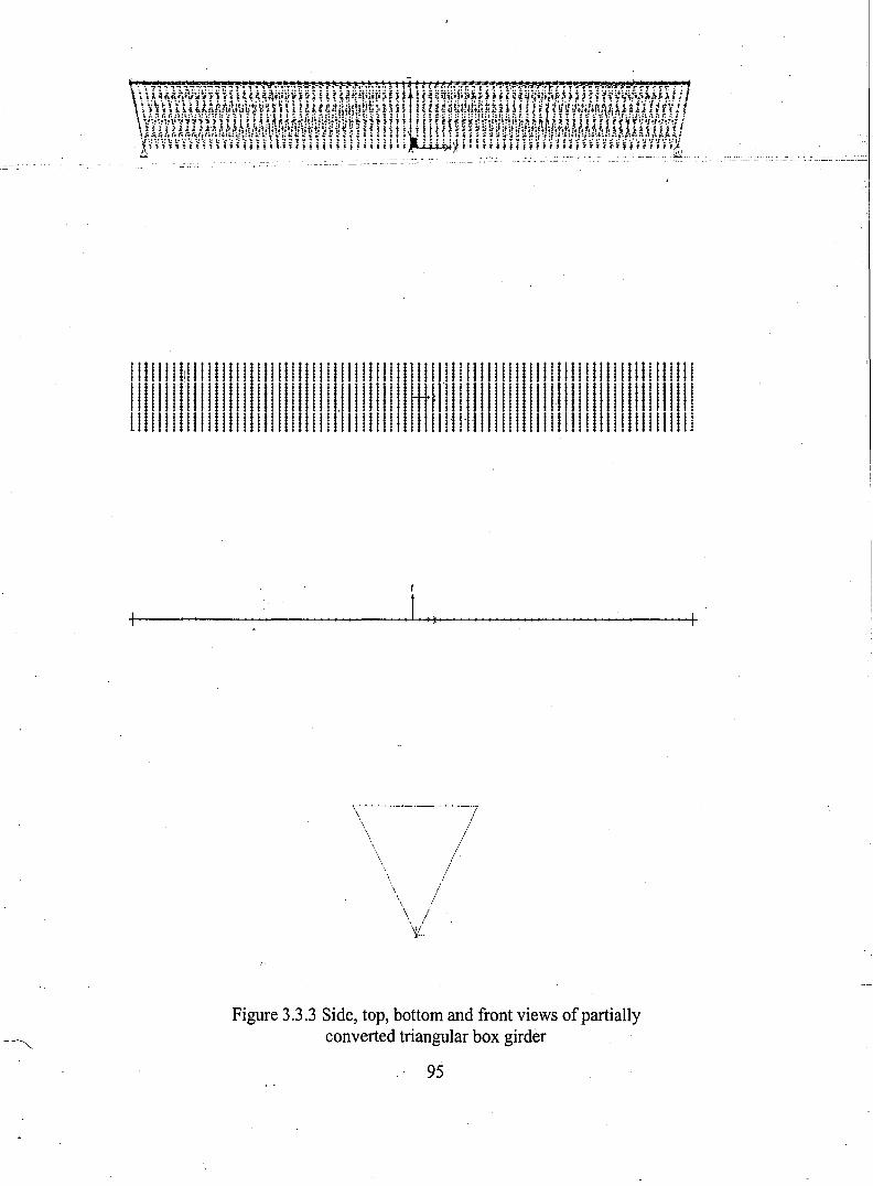
!11111 II!11111111 !III! 11111 !1IIIIIIIIIIIIj !!!11111111111111111111111I111111I1111111!1!!!IIlII!I!!!!!!lll!II!I!II.!!!!!!II!1HtIT!II!I!lll!!I!!!II!II!I!IIII!IIII!II!I111111111 !111111111 !!I!1111I1 !111111111111 !1111'11111111111111111 !III !111111111 !1
r
+-----------1.......,>+-1-----------1-
//
/'/
.. /\ ,\ /\ /''ii.
Figure 3.3.3 Side, top, bottom and front views ofpartiallyconverted triangular box girder
95
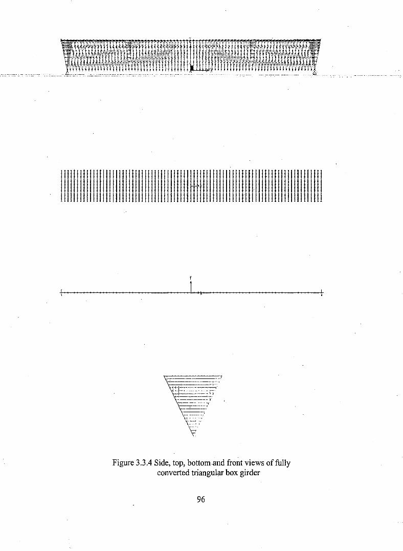
111!1111111111111111111111!IIIIIIIIIIII!l !!1!1111!1111!1!1!lllll.llllllllllllll!11II111111 IIII111111 I111111 IIIIIIII IIIII II Httill IIIIIIII IIII 1·11111 IIIIIIIII III IIIIIIIIIIIIIIIIIIIIIIIIII!IIIIIIIIIIIIIIIIIIIIIIIIIIIIIIIIHlllllllllllllllllllllll
r+- I_,*'~ --+
:_~...:..~~:.:=:~~=::-'.p::::.:=-:::::==p;
----·":'"7
Figure 3.3.4 Side, top, bottom and front views of fullyconverted triangular box girder
96
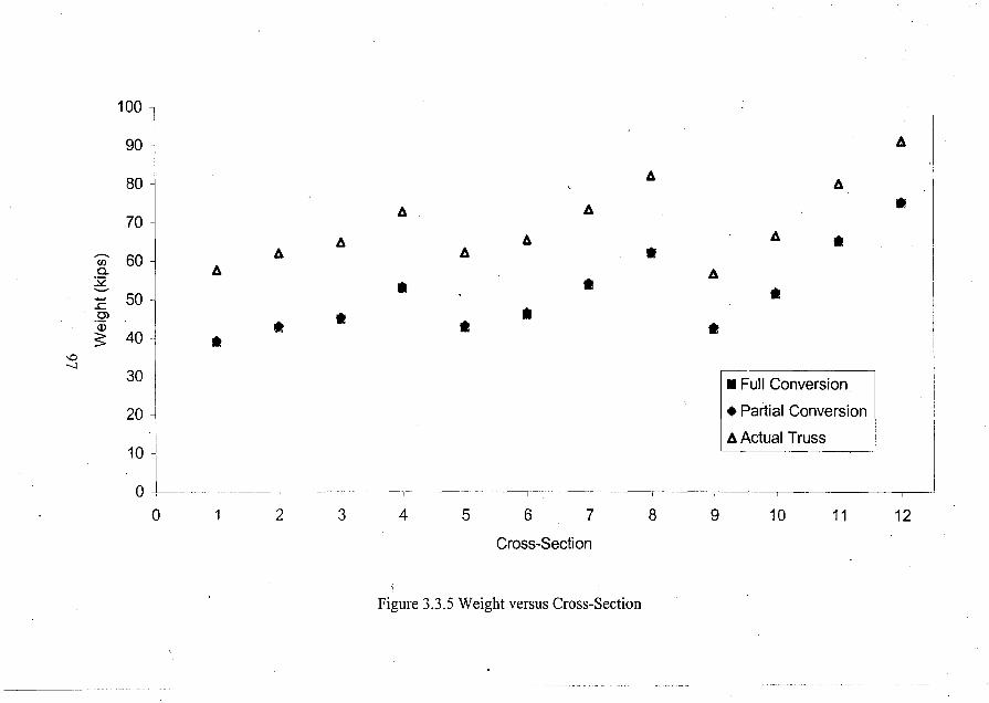
'"--..l
100
90
80
70
(j) 60.9-..:.::.........
. :c 50
..2>Q)
S 40-
30
::L-
A
Ill!
A
Ill!
A
Ill!
A
AA
A •A
A A Ill!A •
AIll! Ill!
Ill!Ill!
Ill! Ill!
• Full Conversion
• Partial Conversion
A Actual Truss
o 2 3 4 5 6 7 8 9 10 11 12
Cross-Section
Figure 3.3.5 Weight versus Cross-Section
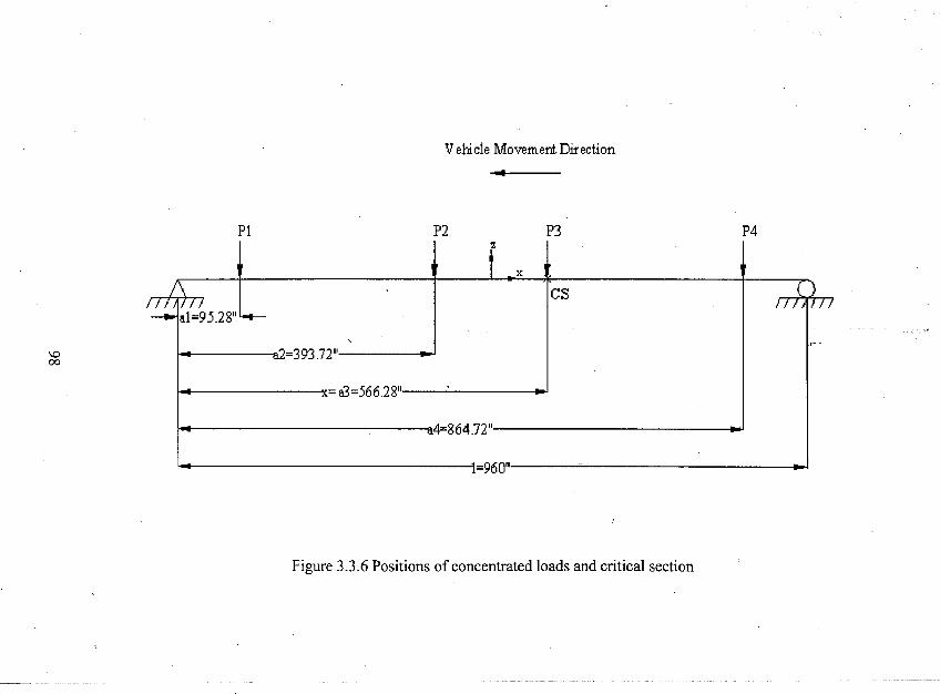
Vehic1e Movement Direction
Pi P2 P3 P4
\000
'" f/\
•r II V77
x •
-ai 95.28"L.t-
CS l)
,
I C I rm
=393.72" ---
,- -
-x 83=566.28" ---l..- -a4=864.72" ---
i=9I"in"
Figure 3.3.6 Positions of concentrated loads and critical section
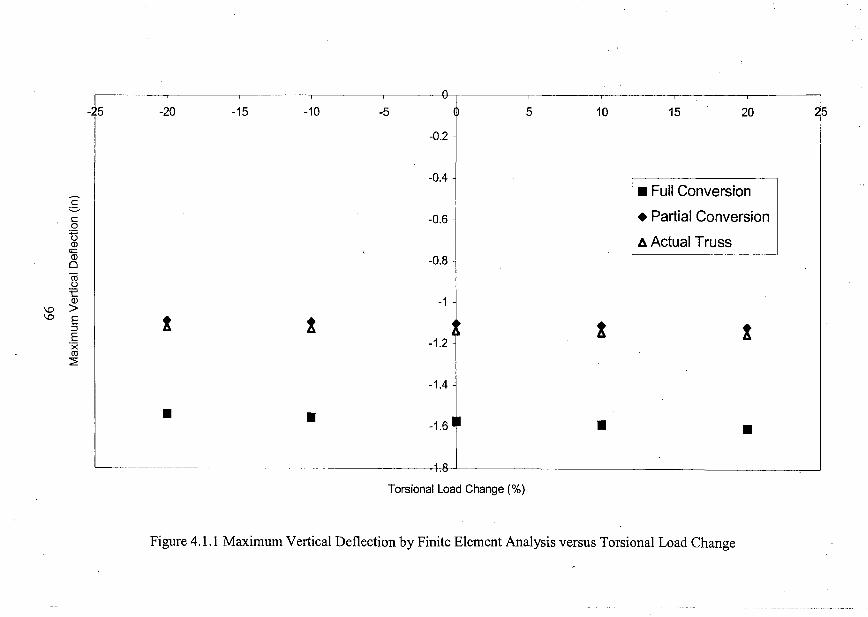
-A5 -20 -15 -10 -5 Of 5 10 15 20
-0.2
-0.4• Full Conversion
c= • Partial Conversionc -0.60
UJj, Actual TrussQl
'a3 -0.80rou:e
-1Ql
\0 >\0 E I I
-1.2 ,:::l I tE'xro~
I-1.4
• • -1.6 • • •
Torsional Load Change (%)
Figure 4.1.1 Maximum Vertical Deflection by Finite Element Analysis versus Torsional Load Change
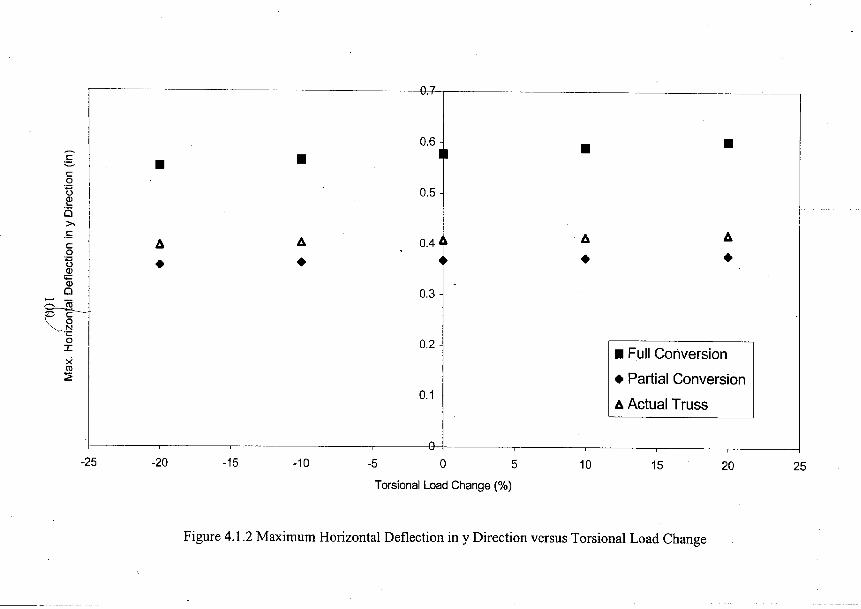
CL2
0.6. • •c I •:.=.. •can I 0.5OJ....is>.
.!:;
I1:1. 0.4t .1:1. 1:1.
c 1:1..2 • • •'0 •OJ<i=OJ0 I 0.3
tt-....a 0.2I • Full Conversionxro
• Partial Conversion:2
0.11:1. Actual Truss
--G--25 -20 -15 -10 -5 0 5 10 15 20 25
Torsional Load Change (%)
Figure 4.1.2 Maximum Horizontal Deflection in y Direction versus Torsional Load Change

~~A A A A-I
cI 0.14 I I-=- Ic
0:;::;t) I 0.12Q)L..
0>< I 0.1s:c0
:;::;0.08t)
Q);;:Q)
0o - 0.06...... co-c
OM 1• Full Conversion0
N'C
• Partial Conversion0Ix A Actual Trussco 0.02~
---9--25 -20 -15 -10 -5 0 5 10 15 20 25
Torsional Load Change (%)
Figure 4.1.3 Maximum Horizontal Deflection in x Direction versus Torsional Load Change
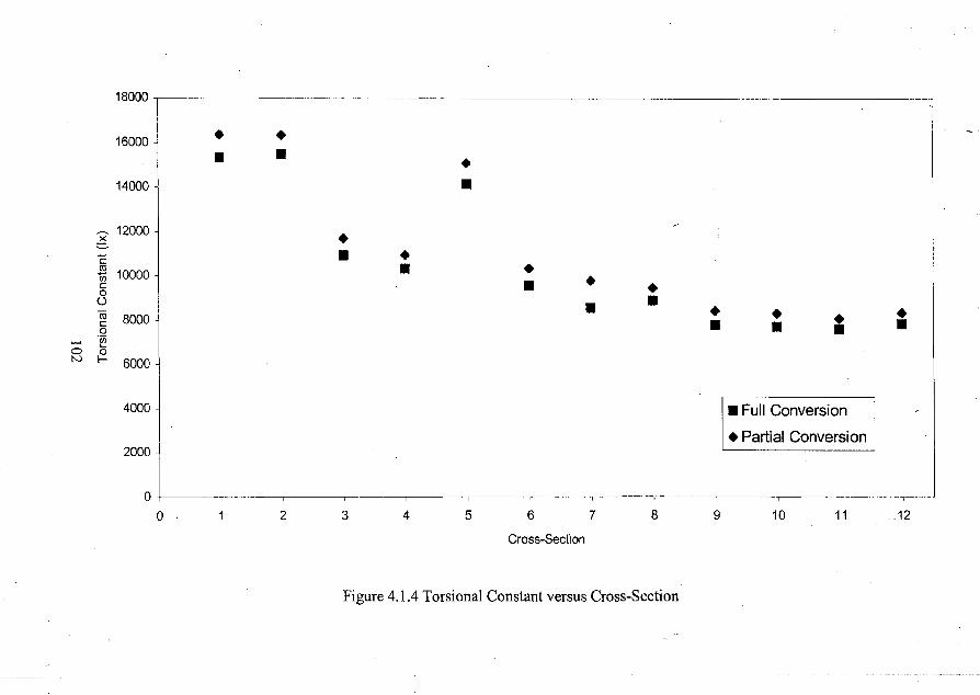
18000
16000 • •• • •
14000 ~ •~ 12000 •~c • •-£l 10000 • •c • • •0 •0 •ro • •
=•c 8000 • • •0
...... ·iiiL-a 0
N I- 6000
4000 ~ I • Full Conversion
• Partial Conversion2000
00 1 2 3 4 5 6 7 8 9 10 11 12
Cross-Section
Figure 4.1.4 Torsional Constant versus Cross-Section
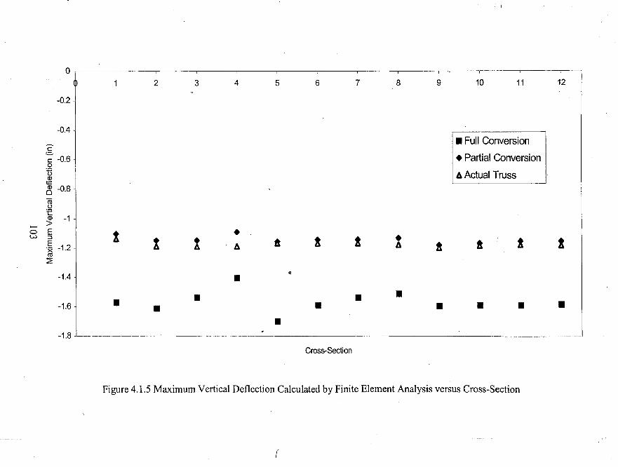
_I' i
OrI I I
1 2 3 4 5 6 7 8 9 10 11 12
-0.2
-0.4
i ~61• Full Conversion
• Partial Conversion
6 Actual Trusst;::
~ -0.8
iiiu'E(]) -1>
0
.; -1.2 j t •w
! ! ! ! •6 a 6 ! ! ! !ro:2
-1.4 J ~•• • •
-1.6 ~ • • • • • • ••I
-1.8
Cross-Section
Figure 4.1.5 Maximum Vertical Deflection Calculated by Finite Element Analysis versus Cross-Section
r
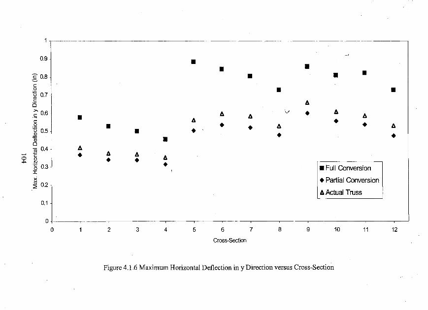
0.9, • • •~ 0.8 ~ • • •c.Q I • •~ 0.7I- 6.0>. V • 6..S 0.6 • 6. 6. 6.c 6. •a • • • 6. • 6.~ 0.5 • •«= • • •OJ0
6.rn 0.4C • 6. 6. 6.0 a • •.j:>. N.§ 0.3 • • Full ConversionI I
X • Partral Conversion~ 0.2
6. Actual Truss0.1
0
0 1 2 3 4 5 6 7 8 9 10 11 12
Cross-Section
Figure 4.1.6 Maximum Horizontal Deflection in y Direction versus Cross-Section
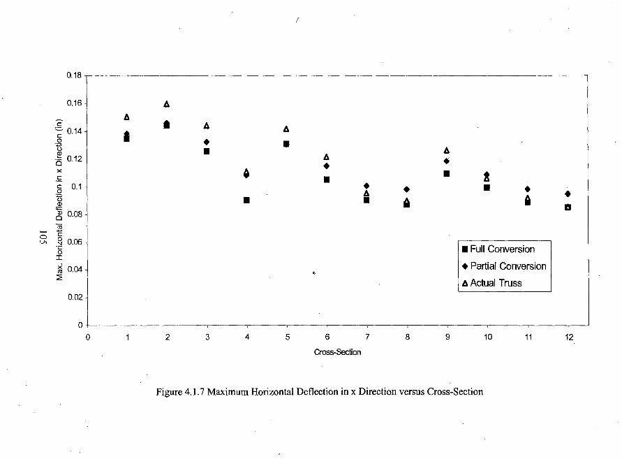
(
0.18
0.16 ~ AA
c • A= 0.14 IA
c.2 • •t5Q) • A
Ais 0.12 ..x 0 •£ • • !c 0.1 • • • •0 An A •Q) • • Il1l<;::: a~ 0.08rn
0 cVI ~ 0.06
'C • Full Conversion0I
~ 0.04 • Partial Conversion:.:E "
A Actual Truss0.02
0
0 1 2 3 4 5 6 7 8 9 10 11 12
Cross-Section
Figure 4.1.7 Maximum Horizontal Deflection in x Direction versus Cross-Section
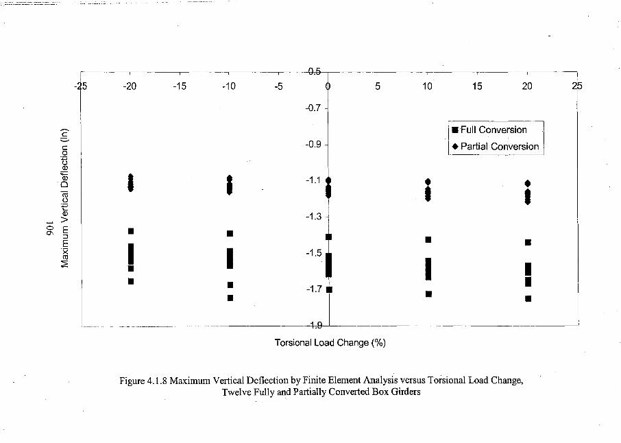
~I --r-
-15 -20 -15 -10 -5 5 10 15 20 2p
-0.7
-0.9 Jc
I• Full Conversion
c-c • Partial Conversion0
UQl
'+=
I IQl-1.1 ~ • •0
m I Il.)
tQl -1.3>
o E • •0\ ::l •E
I •'x Iro
I2 • I• • •• • •
Torsional Load Change (%)
Figure 4.1.8 Maximum Vertical Deflection by Finite Element Analysis versus Torsional Load Change,Twelve Fully and Partially Converted Box Girders
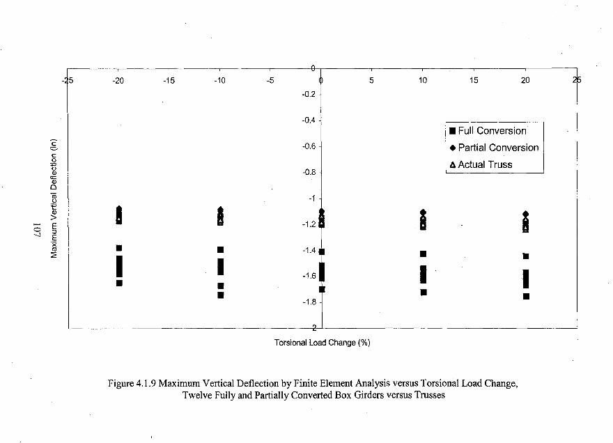
-A5 -20 -15 -10 -5 (!) 5 10 15 20
-0.2
-0.4• Full Conversion
c -0.6 I • Partial Conversion=c.2 A Actual Truss"0(1) -0.8
<;::(1)
0iii -1u:e I I -1.2 , I(1)
i>E0 ::J-.J E'x
I • •co .,4! •~
I •I -1.6 I I• •• • •-1.8
Torsional Load Change (%)
Figure 4.1.9 Maximum Vertical Deflection by Finite Element Analysis versus Torsional Load Change,Twelve Fully and Partially Converted Box Girders versus Trusses
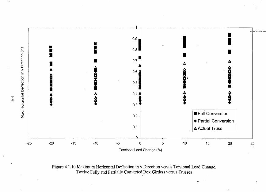
0.9 I •I-~ - Is - 0.8 •c • •0
~ • 0.7 AQJ • AL-
is
I I>. A 0.6 I,.£
Ic.Qtl 0.5QJ -;0:QJ •0
A A"iii A A 0.4
0 C i i ! !00 0N'C 0.30:r:X
I 0.2 ~ I_ Full ConversionOJ:2
• Partial Conversion
o:J I A Actual Truss
I
-25 -20 -15 -10 -5 0 5 10 15 20 25
Torsional Load Change (%)
Figure 4.1.10 Maximum Horizontal Deflection in y Direction versus Torsional Load Change,Twelve Fully and Partially Converted Box Girders versus Trusses
J
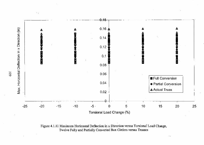
-GAS
- A 0.161 A Ac A'-'
c
I0 I 0.14:;::;<.:lQ)L-a i 0.12x!::
Ic
I 0.1 I I I0:;::;<.:lQ)
;;:: 0.08Q)
0co
0.060 .....\0 C
0
0041• Full ConversionN
'i::0
• Partial ConversionIx A Actual Trussco~ 0.02
-{}
-25 -20 -15 -10 -5 ' 0 5 10 15 20 25
Torsional Load Change (%)
Figure 4.1.11 Maximum Horizontal Deflection in x Direction versus Torsional Load Change,Twelve Fully and Partially Converted Box Girders versus Trusses
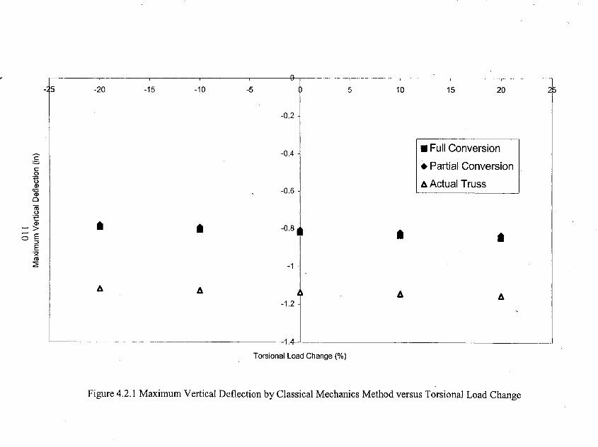
-':15 -20 -15 -10 -5 5 10 15 20 i-0.2
-0.4 • Full Conversion:§.
• Partial Conversionc:0~ 6 Actual TrussQ)<;:: -0.6Q)
0'iiiu'E
IQ) • • -0.8,~> •~ E •o :::l
E'xro~ I -1
6 A , A 6-1.2
.Torsional Load Change (%)
Figure 4.2.1 Maximum Vertical Deflection by Classical Mechanics Method versus Torsional Load Change
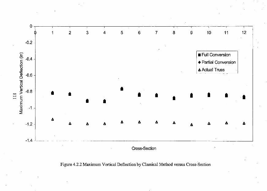
o-,------ I I I
1 2 3 4 5 6 7 8 9 10 11 12I
-0.2
I~.41• Full Conversion
• Partial Conversion
Ii Actual Truss-~ -0.6ro<.:l
_ ~ ~.8 j •• • I • • • I::: E • I:::J • •E'x -1co::E
IIi
A Ii Ii-1.2 ~ Ii Ii Ii A Ii A A A
-1.4 --L-_~_ I
Cross-Section
Figure 4.2.2 Maximum Vertical Deflection by Classical Method versus Cross-Section
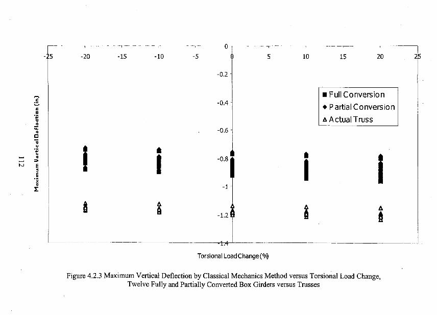
iT-,5 -20 -15 -10 -5 5 10 15 20 r
-0.2
..... • Full Conversionc -0.4..... • Partial Conversionca..
A Actual TrussuQ
"- -0.6Qcvu
I •..-O.8~ •..
I i...... Q...... ::>
IN E:::J
Ex
" -1I:
a 2 -1.23 I A
ft
-.L.
Torsional LoadChange(°1q
Figure 4.2.3 Maximum Vertical Deflection by Classical Mechanics Method versus Torsional Load Change,Twelve Fully and Partially Converted Box Girders versus Trusses
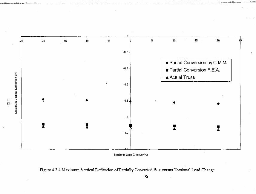
-A5 -20 -15 -10 -5 ill 5 10 15 20
-0.2
I• Partial Conversion by C.M.M.
-OAI • Partial Conversion F.E.A.
~I 6 Actual Truss0
nQ) I -0.6<;::Q)
0
~t:Q) •> • -0.8 TE • •W ::J
E'xl\l2
-1
I I , • •6 6-1.2
Torsional Load Change (%)
Figure 4.2.4 Maximum Vertical Deflection of Partially Converted Box versus Torsional Load Change
t:\
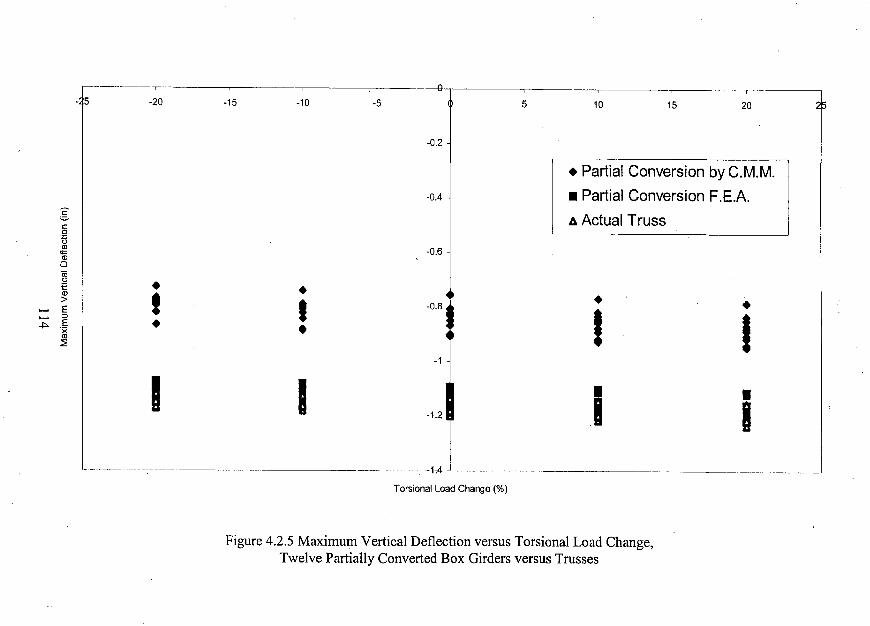
-A5 -20 -15 -10 -5
.021
5 10 15 20
T• Partial Conversion by C.M.M.
-0.4
1 I• Partial Conversion F.E.A.
~I A Actual Trussc:0
UCD I -0.6""CD0
1!i •:e •CD
I ~a, •>
I •...... E
I I:::>...... E •~ 'x •I1l~
-1
I I • •-1.2 I I
Torsional Load Change (%)
Figure 4.2.5 Maximum Vertical Deflection versus Torsional Load Change,Twelve Partially Converted Box Girders versus Trusses

J REFERENCES
t[1] AASHTO. (1998). "Lro:D Bridge Design Specifications for Highway
Bridges." (2nd ed.). American Association of State and Highway
Transportation Officials. Washington, DC.
[2] AISC. (1998). "Load & Resistance Factor Design, Volume I." (2nd ed.).
American Institute of Steel Construction, Inc.
[3] Bresler B., Lin T. Y., Scalzi J. B. (1968). "Design of Steel Structures." (2nd
ed.). John Wiley & Sons, Inc. New York, NY.
[4] Chen W., Lian D. (2000). "Bridge Engineering Handbook." CRC Press LLC,
Boca Raton, FL.
[5] Cohen E., Birdsall B. (1980). "Long-Span Bridges." O.H. Ammann Centennial
Conference. Annals of the New York Academy of Sciences, Volume 352. The
New York Academy of Sciences, New York, NY.
[6] Gelisen G. (2000). "Innovative StructuraJ Guideway System Summer 2000
Pro~edings. "
.[7] HDR. (2000). "Innovative Guideway Design Criteria." HDR Engineering.
Pittsburgh, PA.
[8] Heins C. P. (1975). "Bending and Torsional Design in Structural
Members." Lexington Books, D.C. Heath and Company.
[9] Heins C. P., Snyder J.M., Blank D. (1974). "Lattice Bracing of Box Beams:"
Civil Engineering Report.
115
[10] Johnston B. G. (1976). "Guide to Stability Design Criteria for Metal
Structures." (yd ed.). John Wiley & Sons, Inc. New York, NY..
[11] Kollbrunner C. F., Basler K. (1969). "Torsion in Structures." Springer-
Verlag, Berlin/Heidelberg.
[12] Li G. (1987). "Analysis ofBox Girder and Truss Bridges." China
Academic Publishers, Beij ing and Springer-Verlag, BerlinlHeidelberg.
[13] McDonald R. E. (1973). "Analysis of Open Steel Box Sections with
Bracing." M.S. Thesis, Department of Civil Engineering, Lehigh University,
Bethlehem, PA.
[14] Roik K., Carl 1., Lindner 1. (1972). "Biegetorsionprobleme Gerader
Diinnwandiger Stlibe." Verlag von Wilhelm Ernst & Sohn, Berlin.
[15] SAP2000 Analysis Reference, Volume I. (1997). "Integrated Finite Element
Analysis and Design of Structures." (for version 6.1). Computers and
Structures, Inc. Berkeley, CA.
[16] Shermer, C. L. (1980). "Torsional Strength and Stiffness of Steel Structures."
AISC Engineering Journal, Vol. 17 No.1 / 2nd quarter, Chicago, IL.
116
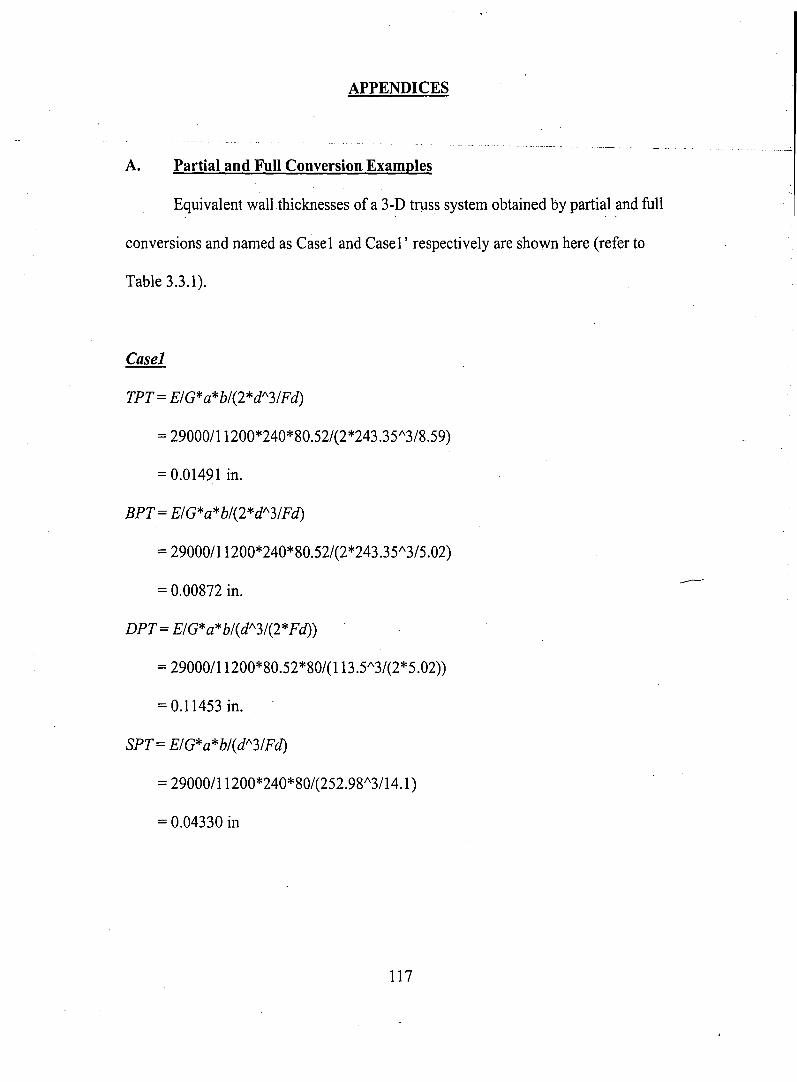
APPENDICES
A. Partial and Full Conversion Examples
Equivalent wall thicknesses of a 3-D truss system obtained by partial and full
conversions and named as Case1 and Casel' respectively are shown here (refer to
Table 3.3.1).
Casel
TPT= E/G*a*b/(2*d/\3/Fd)
= 29000/11200*240*80.52/(2*243.35/\3/8.59)
=0.01491 in.
BPT= E/G*a*b/(2*d/\3/Fd)
=29000/11200*240*80.52/(2*243.35/\3/5.02)
= 0.00872 in.
DPT= E/G*a*b/(d/\3/(2*Fd»)
= 29000/11200*80.52*80/(113.51'3/(2*5.02))
= 0.11453 in.
SPT= E/G*a*b/(d/\3/Fd)
= 29000/11200*240*80/(252.98/\3/14.1)
= 0.04330 in
117
-----
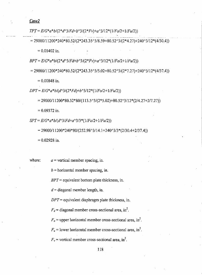
TPT= E/G*a*b/(2*d/\3/Fd+b/\3/(2*Fv)+a/\3/12*(1/Fo/2+ l/Fu/2))
= 29000/11200*240*80.52/(2*243035/\3/8.59+80.52/\3/(2*4.27)+240/\3/12*(4/30.4))
= 0.01402 in.
BPT = E/G*a*b/(2*d/\3/Fd+b/\3/(2*Fv)+a/\3/12*(l/Fo/2+l/Fu/2))
=29000/11200*240*80.52/(2*243.35/\3/5.02+80.52/\3/(2*7.27)+240/\3/12*(4/37.4))
= 0.00848 in.
DPT= E/G*a*b/(d/\3/(2*Fd)+b/\3/12*(1/Fo/2+l/Fu/2))
= 29000/11200*80.52*80/(113.5/\3/(2*5.02)+80.52/\3/12*(2/4.27+2/7.27))
= 0.09372 in.
SPT= E/G*a*b/(d/\3/Fd+a/\3/3*(l/Fo/2+1/Fu/2))
= 29000/11200*240*80/(252.98/\3/14.1+240/\3/3*(2/30.4+2/37.4))
= 0.02928 in.
where: a = vertical member spacing, in.
b = horizontal member spacing, in.
BPT = equivalent bottom plate thickness, in.
d = diagonal member length, in.
DPT = equivalent diaphragm plate thickness, in.
Fd =diagonal member cross-sectional area, in2•
Fo =upper horizontal member cross-sectional area, in2•
Fu = lower horizontal member cross-sectional area, in2•
Fv = vertical member cross-sectional area, in2•
118
E =modulus of elasticity of steel, ksi.
G = shear modulii of steel, ksi .
.sPt~ equivalenfside-plate tfiicKri-ess;·iri·..
TPT = equivalent top plate thickness, in.
119
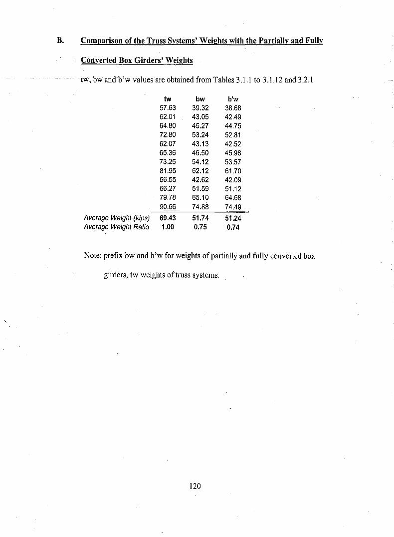
B. Comparison of the Truss Systems' Weights with the Partially and Fully
Converted Box Girders' Weights
-tw,bw andb'w values are obtained from Tables 3.1.1 to 3.1.12 and 3.2.1
tw bw b'w57.63 39.32 38.6862.01 43.05 42.4964.80 45.27 44.7572.80 53.24 52.8162.07 43.13 42.5265.36 46.50 45.9673.25 54.12 53.5781.95 62.12 61.7056.55 42.62 42.0966.27 51.59 51.1279.78 65.10 64.6890.66 74.88 74.49
Average Weight (kips) 69.43 51.74 51.24Average Weight Ratio 1.00 0.75 0.74
Note: prefix bw and b'w for weights ofpartially and fully converted box
girders, tw weights of truss systems.
120
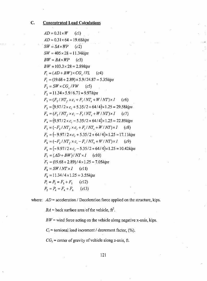
C. Concentrated Load Calculations
AD=0,31xW (e1)
AD = 0,31 x 64 = 19.68kips
SW = SA x WP (c2)
SW =405 x 28 =11.34kips
BW = BA x WP (c3)
BW = 103.3 x 28 = 2.89kips
F;=(AD+BW)xCGzIVL (c4)
F1 =(19.68 + 2.89) x 5.9/24.87 = 5,35kips
Fz =SW x CGz IVW (c5)
Fz = 11.34 x 5.9/6.71 = 9.97kips
F3=(FzINTjxc;+F,INTs+WINT)xI (c6)
F3 = (9.9712 x C; + 5.35/2 + 641 4)x 1.25 = 29.58kips.
F4 = (Fz1NTj xc; - FliNTs +WI NT) x I (c7)
F4 =(9.9712 x C; - 5.35/2 + 64/ 4)x 1.25 =22.89kips
Fs =(-FzINTjxcj+F,INTs+WINT)xI (c8)
Fs =(-9.97/2xc; +5,35/2+64/4)x1.25 =17.11kips
F6 =(-FzINTjxcj-F,INTs+WINT)xI (c9)
F6 = (- 9.97 /2 x c; - 5.3512 + 641 4)x 1.25 =10.42kips
F7 = (AD+BW)I NTxI (elO)
F7 = (19.68+ 2.89)1 4x1.25 = 7.05kips
Fg=SWINTxI (ell)
Fg=11,3414 x 1.25 =3.55kips
~=P3=F3+Fs (el2)
Pz =P4 =F4 +F6 (el3)
where: AD =acceleration 1Deceleration force applied on the structure, kips.
BA = back surface area of the vehicle, fe.
BW= wind force acting on the vehicle along negative x-axis, kips.
Ci = torsional load increment 1decrement factor, (%).
CGz =center of gravity ofvehicle along z-axis, ft.
121
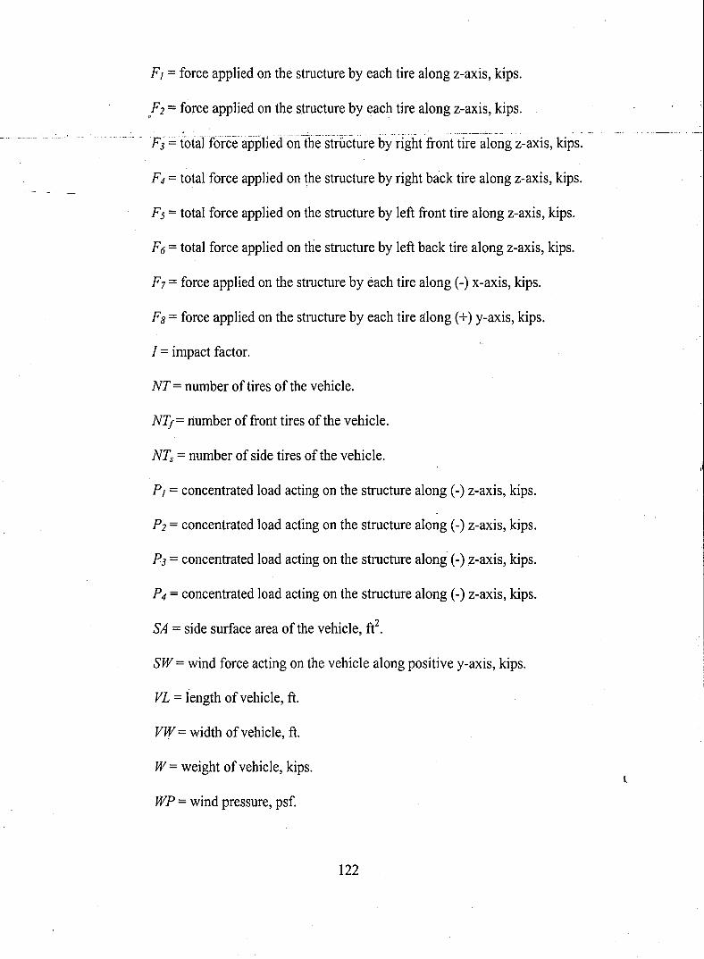
F j = force applied on the structure by each tire along z-axis, kips.
F2 = force applied on the structure by each tire along z-axis,kips., . .
F4 = total force applied on the structure by right back tire along z-axis, kips.
Fs = total force applied on the structure by left front tire along z-axis, kips.
F6 = total force applied on the structure by left back tire along z-axis, kips.
F7 = force applied on the structure by each tire along (-) x-axis, kips.
F8 = force applied on the structure by each tire along (+) y-axis, kips.
I = impact factor.
NT = number of tires of the vehicle.
NTf= number of front tires of the vehicle.
NTs = number of side tires of the vehicle.
P j = concentrated load acting on the structure along (-) z-axis, kips.
P2 = concentrated load acting on the structure along (-) z-axis, kips.
P3 = concentrated load acting on the structure along (-) ,z-axis, kips.
P4 = concentrated load acting on the structure along (-) z-axis, kips.
SA = side surface area of the vehicle, ft2.
SW = wind force acting on the vehicle along positive y-axis, kips.
VL = length ofvehicle, ft.
VW = width of vehicle, ft.
W= weight ofvehicle, kips.
WP = wind pressure, psf.
122
l
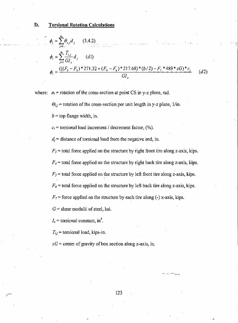
D. Torsional Rotation Calculations
m
¢Ji = ''L/Jj,jd j (3.4.2)j=I-- .
m T¢Jj = I ~dj (dl)
j=1 Glx
"'. = (((F3 -Fs)*271,32+(F4 -F6 )*217.68)*(b/2)-F7 *489*zG)*c j (d2)'1'1 GI
x
where: fJi =rotation of the cross-section at point CS in y-z plane, rad.
eij =rotation of the cross-section per unit length in y-z plane, l/in.
b =top flange width, in.
Ci = torsional load increment / decrement factor, (%).
dj = distance of torsional load from the negative end, in.
F3 =total force applied on the structure by right front tire along z-axis, kips.
F4 =total force applied on the structure by right back tire along z-axis, kips.
F5 = total force applied on the structure by left front tire along z-axis, kips.
F6 =total force applied on the structure by left back tire along z-axis, kips.
F7 = force applied on the structure by each tire along (-) x-axis, kips.
G =shear modulii of steel, ksi.
I . I . 4x =torslOna constant, m .
Tij =torsional load, kips-in.
zG = center of gravity ofbox section along z-axis, in.
123
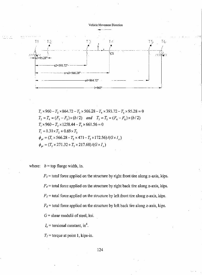
Vehicle Movement Direction
-----
T] T2 T~: Til TS TE:,
niii I ----fL.;-· .. . - (- L-r~s-- --- ~------------- --r ;7 lb---jal=95.28" -- I
i
....... - .. ·-02=393.72"' ... - -_.J I I
---x=a3=566.28"------
-------·---:a4=864.72"'----------o...,.!
'-------------1=960"'--------------'
1; X 960 - T2 X 864.72 - T3 X 566.28 - T4 X 393.72 - Ts X 95.28 = 0
T2 =T4 =(F3 -Fs)x(b/2) and T3 =Ts =(F4 -F6 )x(b/2)
1; X 960 - T2 x 1258.44 - T3 x 661.56 =0
1; =1.31xT2 +0.69xT3
tPpi =(1; X 566.28 - T2 X 471- T3 x 172.56)/(G X Ix)
tPpi = (T2 X 271.32+T3 x217.68)/(GxIJ
where: b =top flange width, in.
F3 =total-force applied on the structure by right front tire along z-axis, kips.
F4 =total force applied on the structure by right back tire along z-axis, kips.
Fs = total force applied on the structure by left front tire along z-axis, kips.
F6 =total force applied on the structure by left back tire along z-axis, kips.
G = shear modulii of steel, ksi.
1 . I . 4x =torslOna constant, III .
TI =torque at point 1, kips-in.
124
T2 =torque at point 2, kips-in.
T3 =torque at point 3, kips-in.
T4 = torque at point 4, kips-in.
T5 = torque at point 5, kips-in.
T6 =torque at point 6, kips-in.
{:}pi= partial rotation of the cross-section at point CS in y-z plane, rad.
125
\

Gokhan Gelisen, the only son of Dr. Orhan and Dt. Yasemin Gelisen, was
born February ~9, 1978 in Ankara, Turkey.
In June 1995, he graduated from TED Ankara High School. He attended
Istanbul Technical University in Istanbul from September 1995 to June 1996 and
Middle East Technical University in Ankara from September 1996 to June 1999 when
he received his Bachelor of Science degree in Civil Engineering.
In September 2000, he enrolled in the Graduate School of Lehigh University.
He worked as a Student Assistant in Council on Tall Buildings and Urban Habitat at
Fritz Engineering Laboratory from December 1999 to May 2000. From June 2000 to
August 2000 the author was involved in a Pennsylvania Infrastructure Technology
Alliance Project as a Research Assistant at Research & Development Department of
DaimlerChrysler Rail Systems Inc. - ADtranz Na, Pittsburgh in conjunction with
Lehigh University and Carnegie Mellon University, which will guide him to choose
his thesis topic. Starting in September 2000, he has been holding the Teaching
Assistant position in Lehigh University while working for his Master of Science
Degree in Civil Engineering.
126

·END.. OF
TITl:E