Embed Size (px)
Citation preview
PDF generated from XML JATS4R by RedalycProject academic non-profit, developed under the open access initiative
Revista de la Asociación Latinoamericana deControl de Calidad, Patología y Recuperación de laConstrucciónISSN: [email protected]ón Latinoamericana de Control de Calidad,Patología y Recuperación de la Construcción, A. C.México
Evaluation of pathological problemsassociated with carbonation and sulfates ina concrete tower with more than 50 yearsin service
Maldonado-Bandala, E. E.Evaluation of pathological problems associated with carbonation and sulfates in a concrete tower with more than50 years in serviceRevista de la Asociación Latinoamericana de Control de Calidad, Patología y Recuperación de la Construcción,vol. 8, no. 1, 2018Asociación Latinoamericana de Control de Calidad, Patología y Recuperación de la Construcción, A. C., MéxicoAvailable in: https://www.redalyc.org/articulo.oa?id=427654656017DOI: https://doi.org/10.21041/ra.v8i1.284
This work is licensed under Creative Commons Attribution-NonCommercial-NoDerivs 4.0 International.
Revista de la Asociación Latinoamericana de Control de Calidad, Patología y Recuperación de laConst...,2018, vol. 8, no. 1, January-April, ISSN: 2007-6835
PDF generated from XML JATS4R by RedalycProject academic non-profit, developed under the open access initiative 94
Evaluation of pathological problems associated with carbonation and sulfates in aconcrete tower with more than 50 years in serviceEvaluación de problemas patológicos asociados a carbonatación y sulfatos en una torre de concreto con más de 50años de servicioAvaliação de patologias associadas com carbonatação e sulfatos em uma torre de concreto com mais de 50 anos deserviço
E. E. Maldonado-BandalaUniversidad Veracruzana, Mé[email protected]
DOI: https://doi.org/10.21041/ra.v8i1.284Redalyc: https://www.redalyc.org/articulo.oa?
id=427654656017
Received: 14 December 2017Accepted: 22 December 2017
Published: 31 January 2018
Abstract:
is work presents and discuss the results of a corrosion inspection, as well as a repair proposal for the external walls of a reinforcedconcrete tower which is in the southern coast of the Veracruz state. e inspection included a drone guided damage surveytogether with physical, chemical, mechanical and electrochemical tests that allowed the concrete characterization and corrosiondamage. e governing deterioration mechanism of the structure was carbonation of concrete. However, the sulfate emission inthis industrial environment was reflected on the compressive resistance, cracks and delaminations. ese conditions were takeninto account on the proposed actions for repairing and extending the service life of the structure.Keywords: inspection, tower, reinforced concrete, diagnosis, service life.
Resumen:
En este trabajo se presentan y discuten los resultados de la inspección por corrosión, y una propuesta de reparación de losmuros exteriores de una torre de concreto reforzado localizada en la costa sur del estado de Veracruz. La inspección incluyó unlevantamiento de daños con un dron, y ensayos físicos, químicos, mecánicos y electroquímicos que permitieron caracterizar elconcreto y los daños por corrosión. El mecanismo gobernante de la corrosión en la estructura estudiada fue la carbonatación. Sinembargo, la emisión de sulfatos en ese ambiente industrial se reflejó en la resistencia a la compresión, grietas y delaminaciones. Lascondiciones anteriores fueron contempladas en las acciones propuestas de reparación para extender su vida de servicio.Palabras clave: inspección, torre, concreto reforzado, diagnóstico, vida de servicio.
Resumo:
Este artigo apresenta e discute os resultados da inspeção de corrosão e uma proposta para reparar as paredes exteriores de uma torrede concreto armado localizada na costa sul do estado de Veracruz. A inspeção incluiu uma pesquisa de danos com um drone e testesfísicos, químicos, mecânicos e eletroquímicos que permitiram a caracterização de danos de concreto e corrosão. O mecanismogovernante de corrosão na estrutura estudada foi a carbonatação. No entanto, a emissão de sulfatos neste ambiente industrialfoi refletida na resistência à compressão, fissuras e delaminações. As condições acima foram contempladas nas ações de reparopropostas para ampliar sua vida útil.Palavras-chave: inspecção, torre, concreto armado, taxa de corrosão, diagnóstico, vida útil.
1. INTRODUCTION
As part of a recent reform of the energy sector in Mexico, the federal government is required to purchaseunproductive properties and buildings from the private sector. Many of these have been abandoned for
Author notes
E. E. Maldonado-Bandala. Evaluation of pathological problems associated with carbonation and sulfa...
PDF generated from XML JATS4R by RedalycProject academic non-profit, developed under the open access initiative 95
decades and exhibit high degrees of degradation due in part to accelerated corrosion phenomena resultingfrom lack of maintenance and exposure to aggressive environments.
Corrosion of reinforced concrete structures is a serious problem, particularly in industrial environments.It can manifest as intense pathological signs which can lead to critical problems in function, safety, excessiverehabilitation and service costs and loss of appearance; indeed, depending on the degree of damage, it canput human life at risk (Helene, 2003; Sulaimani 1992, Andrade 1992; del Valle et al., 2006).
Many of the properties to be acquired by the federal government are petroleum industry installations.Restoring these to productive levels of functioning will require rehabilitation. e causes for corrosion-related failures will need to be investigated as well as the complex relationship between the physical, chemicaland mechanical properties of the concrete and steel reinforcement.
e present study responds to the need to rehabilitate and return to operation reinforced concrete towersin petroleum industry installations in the southern portion of the state of Veracruz, Mexico. ese are a vitalasset in this industry, which is economically significant in the region. e towers were evaluated with anemphasis on durability. is involved destructive and non-destructive assays, visual inspection using an aerialdrone, and electrochemical, chemical and mechanical tests. ese evaluations are discussed and a structuraldiagnosis presented highlighting the mechanisms that intensified corrosion. e final objective is to identifythe corrective measures needed to extend the use life of these existing assets.
2. INSPECTION PLAN
2.1 Preliminary inspection
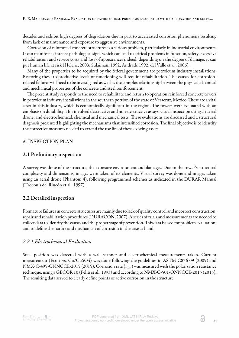
A survey was done of the structure, the exposure environment and damages. Due to the tower’s structuralcomplexity and dimensions, images were taken of its elements. Visual survey was done and images takenusing an aerial drone (Phantom 4), following programmed schemes as indicated in the DURAR Manual(Troconis del Rincón et al., 1997).
2.2 Detailed inspection
Premature failures in concrete structures are mainly due to lack of quality control and incorrect construction,repair and rehabilitation procedures (DURACON, 2007). A series of trials and measurements are needed tocollect data to identify the causes and the proper stage of prevention. is data is used for problem evaluation,and to define the nature and mechanism of corrosion in the case at hand.
2.2.1 Electrochemical Evaluation
Steel position was detected with a wall scanner and electrochemical measurements taken. Currentmeasurement (Ecorr vs. Cu/CuSO4) was done following the guidelines in ASTM C876-09 (2009) andNMX-C-495-ONNCCE-2015 (2015). Corrosion rate (icorr) was measured with the polarization resistancetechnique, using a GECOR 10 (Feliú et al., 1993) and according to NMX-C-501-ONNCCE-2015 (2015).e resulting data served to clearly define points of active corrosion in the structure.
Revista de la Asociación Latinoamericana de Control de Calidad, Patología y Recuperación de laConst...,2018, vol. 8, no. 1, January-April, ISSN: 2007-6835
PDF generated from XML JATS4R by RedalycProject academic non-profit, developed under the open access initiative 96
2.2.2 Physicochemical Evaluation
Cores were extracted from the structure to directly test concrete quality and its potential to corrode thereinforcement. Assays were done of carbonation depth (NMX-C-515-ONNCCE-2016, 2016), chlorideconcentration (ASTM C114-05, 2005), and sulfate chemical attack. Concrete resistance to simplecompression was tested with a hardened concrete core test (NMX-C-083-ONNCCE-2010, 2010).
3. RESULTS AND DISCUSSION
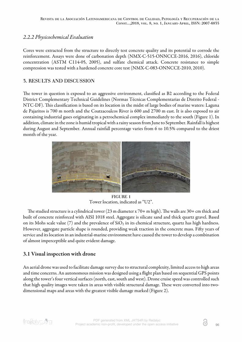
e tower in question is exposed to an aggressive environment, classified as B2 according to the FederalDistrict Complementary Technical Guidelines (Normas Técnicas Complementarias de Distrito Federal -NTC-DF). is classification is based on its location in the midst of large bodies of marine waters: Lagunade Pajaritos is 700 m north and the Coatzacoalcos River is 600 and 2700 m east. It is also exposed to aircontaining industrial gases originating in a petrochemical complex immediately to the south (Figure 1). Inaddition, climate in the zone is humid tropical with a rainy season from June to September. Rainfall is highestduring August and September. Annual rainfall percentage varies from 6 to 10.5% compared to the driestmonth of the year.
FIGURE 1Tower location, indicated as “U2”.
e studied structure is a cylindrical tower (23 m diameter x 70+ m high). e walls are 30+ cm thick andbuilt of concrete reinforced with AISI 1018 steel. Aggregate is silicate sand and thick quartz gravel. Basedon its Mohs scale value (7) and the prevalence of SiO2 in its chemical structure, quartz has high hardness.However, aggregate particle shape is rounded, providing weak traction in the concrete mass. Fiy years ofservice and its location in an industrial-marine environment have caused the tower to develop a combinationof almost imperceptible and quite evident damage.
3.1 Visual inspection with drone
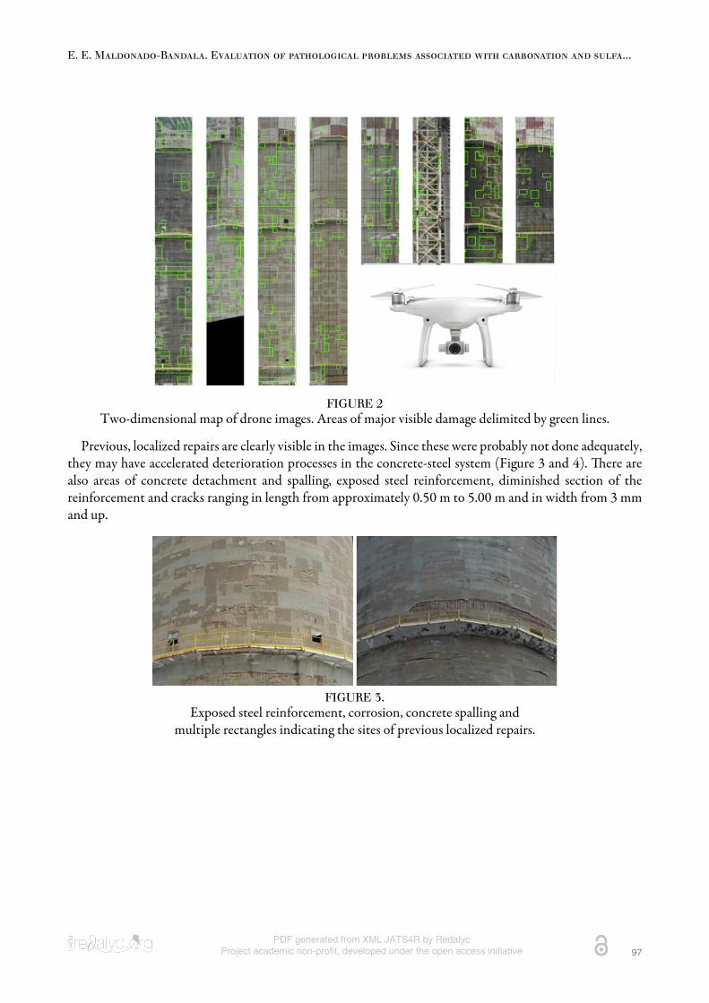
An aerial drone was used to facilitate damage survey due to structural complexity, limited access to high areasand time concerns. An autonomous mission was designed using a flight plan based on sequential GPS pointsalong the tower’s four vertical surfaces (north, east, south and west). Drone cruise speed was controlled suchthat high quality images were taken in areas with visible structural damage. ese were converted into two-dimensional maps and areas with the greatest visible damage marked (Figure 2).
E. E. Maldonado-Bandala. Evaluation of pathological problems associated with carbonation and sulfa...
PDF generated from XML JATS4R by RedalycProject academic non-profit, developed under the open access initiative 97
FIGURE 2Two-dimensional map of drone images. Areas of major visible damage delimited by green lines.
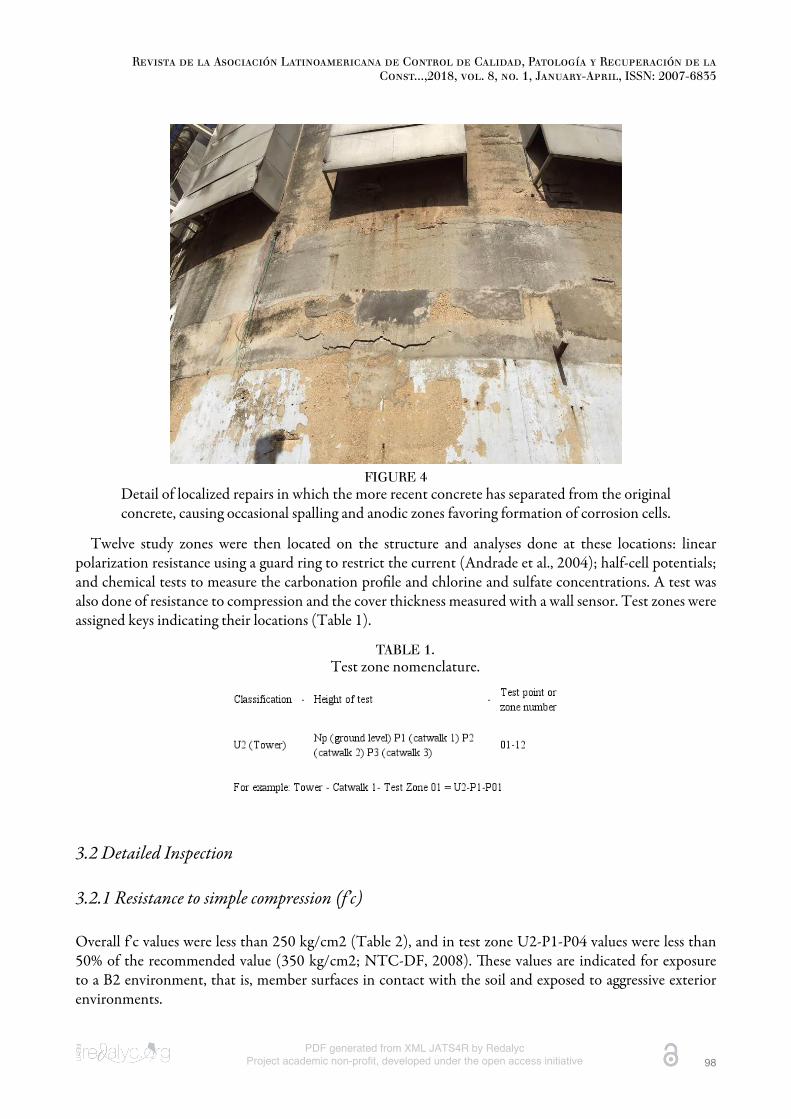
Previous, localized repairs are clearly visible in the images. Since these were probably not done adequately,they may have accelerated deterioration processes in the concrete-steel system (Figure 3 and 4). ere arealso areas of concrete detachment and spalling, exposed steel reinforcement, diminished section of thereinforcement and cracks ranging in length from approximately 0.50 m to 5.00 m and in width from 3 mmand up.
FIGURE 3.Exposed steel reinforcement, corrosion, concrete spalling and
multiple rectangles indicating the sites of previous localized repairs.
Revista de la Asociación Latinoamericana de Control de Calidad, Patología y Recuperación de laConst...,2018, vol. 8, no. 1, January-April, ISSN: 2007-6835
PDF generated from XML JATS4R by RedalycProject academic non-profit, developed under the open access initiative 98
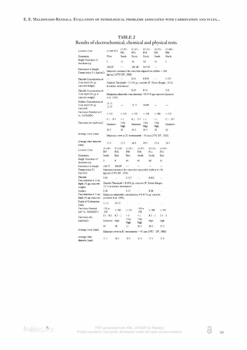
FIGURE 4Detail of localized repairs in which the more recent concrete has separated from the originalconcrete, causing occasional spalling and anodic zones favoring formation of corrosion cells.
Twelve study zones were then located on the structure and analyses done at these locations: linearpolarization resistance using a guard ring to restrict the current (Andrade et al., 2004); half-cell potentials;and chemical tests to measure the carbonation profile and chlorine and sulfate concentrations. A test wasalso done of resistance to compression and the cover thickness measured with a wall sensor. Test zones wereassigned keys indicating their locations (Table 1).
TABLE 1.Test zone nomenclature.
3.2 Detailed Inspection
3.2.1 Resistance to simple compression (f’c)
Overall f’c values were less than 250 kg/cm2 (Table 2), and in test zone U2-P1-P04 values were less than50% of the recommended value (350 kg/cm2; NTC-DF, 2008). ese values are indicated for exposureto a B2 environment, that is, member surfaces in contact with the soil and exposed to aggressive exteriorenvironments.
E. E. Maldonado-Bandala. Evaluation of pathological problems associated with carbonation and sulfa...
PDF generated from XML JATS4R by RedalycProject academic non-profit, developed under the open access initiative 99
TABLE 2Results of electrochemical, chemical and physical tests.
Revista de la Asociación Latinoamericana de Control de Calidad, Patología y Recuperación de laConst...,2018, vol. 8, no. 1, January-April, ISSN: 2007-6835
PDF generated from XML JATS4R by RedalycProject academic non-profit, developed under the open access initiative 100
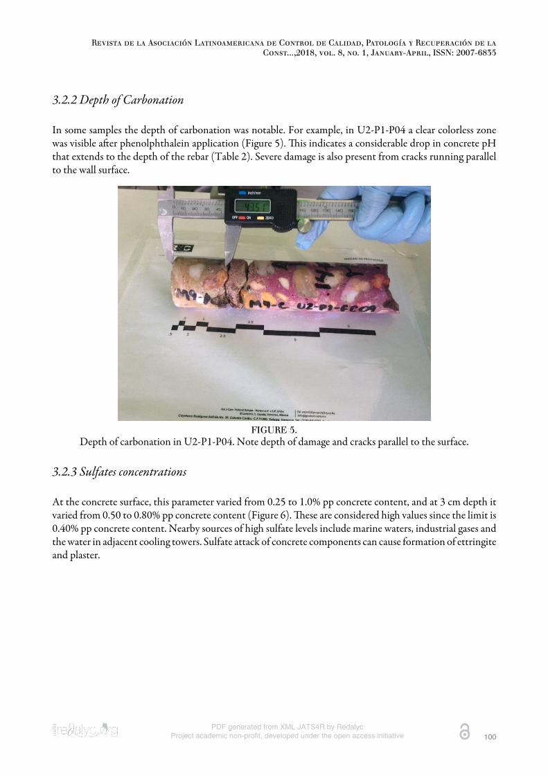
3.2.2 Depth of Carbonation
In some samples the depth of carbonation was notable. For example, in U2-P1-P04 a clear colorless zonewas visible aer phenolphthalein application (Figure 5). is indicates a considerable drop in concrete pHthat extends to the depth of the rebar (Table 2). Severe damage is also present from cracks running parallelto the wall surface.
FIGURE 5.Depth of carbonation in U2-P1-P04. Note depth of damage and cracks parallel to the surface.
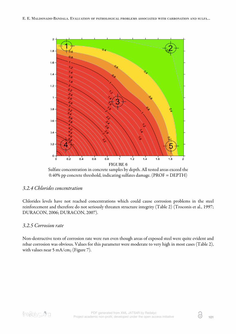
3.2.3 Sulfates concentrations
At the concrete surface, this parameter varied from 0.25 to 1.0% pp concrete content, and at 3 cm depth itvaried from 0.50 to 0.80% pp concrete content (Figure 6). ese are considered high values since the limit is0.40% pp concrete content. Nearby sources of high sulfate levels include marine waters, industrial gases andthe water in adjacent cooling towers. Sulfate attack of concrete components can cause formation of ettringiteand plaster.
E. E. Maldonado-Bandala. Evaluation of pathological problems associated with carbonation and sulfa...
PDF generated from XML JATS4R by RedalycProject academic non-profit, developed under the open access initiative 101
FIGURE 6Sulfate concentration in concrete samples by depth. All tested areas exceed the0.40% pp concrete threshold, indicating sulfates damage. (PROF = DEPTH)
3.2.4 Chlorides concentration
Chlorides levels have not reached concentrations which could cause corrosion problems in the steelreinforcement and therefore do not seriously threaten structure integrity (Table 2) (Troconis et al., 1997;DURACON, 2006; DURACON, 2007).
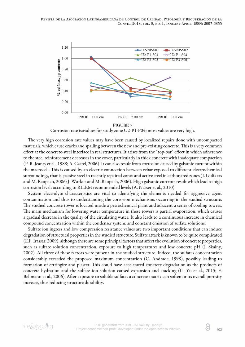
3.2.5 Corrosion rate
Non-destructive tests of corrosion rate were run even though areas of exposed steel were quite evident andrebar corrosion was obvious. Values for this parameter were moderate to very high in most cases (Table 2),with values near 5 mA/cm2 (Figure 7).
Revista de la Asociación Latinoamericana de Control de Calidad, Patología y Recuperación de laConst...,2018, vol. 8, no. 1, January-April, ISSN: 2007-6835
PDF generated from XML JATS4R by RedalycProject academic non-profit, developed under the open access initiative 102
FIGURE 7Corrosion rate isovalues for study zone U2-P1-P04; most values are very high.
e very high corrosion rate values may have been caused by localized repairs done with uncompactedmaterials, which cause cracks and spalling between the new and pre-existing concrete. is is a very commoneffect at the concrete-steel interface in real structures. It arises from the “top-bar” effect in which adherenceto the steel reinforcement decreases in the cover, particularly in thick concrete with inadequate compaction(P. R. Jeanty et al., 1988; A. Castel, 2006). It can also result from corrosion caused by galvanic current withinthe macrocell. is is caused by an electric connection between rebar exposed to different electrochemicalsurroundings, that is, passive steel in recently repaired zones and active steel in carbonated zones (J. Gulikersand M. Raupach, 2006; J. Warkus and M. Raupach, 2006). High galvanic currents result which lead to highcorrosion levels according to RILEM recommended levels (A. Nasser et al., 2010).
System electrolyte characteristics are vital to identifying the elements needed for aggressive agentcontamination and thus to understanding the corrosion mechanisms occurring in the studied structure.e studied concrete tower is located inside a petrochemical plant and adjacent a series of cooling towers.e main mechanism for lowering water temperature in these towers is partial evaporation, which causesa gradual decrease in the quality of the circulating water. It also leads to a continuous increase in chemicalcompound concentration within the condenser system, and constant emission of sulfate solutions.
Sulfate ion ingress and low compression resistance values are two important conditions that can inducedegradation of structural properties in the studied structure. Sulfate attack is known to be quite complicated(E.F. Irassar, 2009), although there are some principal factors that affect the evolution of concrete properties,such as sulfate solution concentration, exposure to high temperatures and low concrete pH (J. Skalny,2002). All three of these factors were present in the studied structure. Indeed, the sulfates concentrationconsiderably exceeded the proposed maximum concentration (C. Andrade, 1998), possibly leading toformation of ettringite and plaster. is could have accelerated concrete degradation as the products ofconcrete hydration and the sulfate ion solution caused expansion and cracking (C. Yu et al., 2015; F.Bellmann et al., 2006). Aer exposure to soluble sulfates a concrete matrix can soen or its overall porosityincrease, thus reducing structure durability.
E. E. Maldonado-Bandala. Evaluation of pathological problems associated with carbonation and sulfa...
PDF generated from XML JATS4R by RedalycProject academic non-profit, developed under the open access initiative 103
3.3 Rehabilitation-reinforcement proposal
Aer the inspection, recommendations were made to immediately begin repair, rehabilitation andreinforcement. A general description is provided below, but a full account is contained in the correspondingexecutive report. Increasing the structure’s residual use life will require that the entire tower be addressed toprevent the creation of zones vulnerable to galvanic effects.
PreliminariesDeteriorated and/or contaminated concrete should only be removed from anodic zones. Steel rebar
needs to be cleaned and the substrate prepared following official guidelines (NMX-C-518-ONNCCE-2016,2016). If deemed necessary aer evaluation, rebar should be replaced.
Stage 1e high corrosion rate results suggest the presence of zones in which loss of steel reinforcement section is
advanced. In places where the decrease in original nominal diameter exceeds 10% the structure needs to bereinforced through substitution of the damaged rebar with rebar of the original diameter and with the sameyield point (fy) to meet applicable regulations (NMX-B-457-CANACERO-2013, 2013). Repair sequenceand geometry must meet the guidelines in the Rehabilitar network manual (Helene, 2003).
Stage 2Due to the structure’s geometrical condition and the difficulty of building centering and applying
spray concrete at high altitudes, section recovery is best done using prepared structural repair mortarcontaining sulfate resistant (RS) Portland cement complying with applicable regulations (NMX-C-414-ONNCCE-2014, 2014; NMX-C-418-ONNCCE-2015, 2015). It will need to be sufficiently fluid to allowfor manual application.
Stage 3To reduce the probability of corrosion in repaired areas, calcium nitrate corrosion inhibitor will need to
be applied according to ASTM C494 / C494M-17 (2017).Stage 4Low resistance to compression in the structure’s concrete will require reinforcement of the base
with carbon fiber reinforced polymer (CFRP) up to the catwalk 1 (P1) level. is system will increaseconfinement, and resistance to shear force and external loads (e.g. winds and earthquakes), withoutcompromising structure ductility (ACI-440R-07, 2007).
Stage 5A chloride-impermeable anti-carbonation covering will need to be applied with the capacity to bridge
cracks and including chemical components complying with ASTM C494 / C494M-17 (2017). If cracksappear they should be covered since these are the primary point of contaminant ingress.
4. CONCLUSIONS
Use of an aerial drone for inspection of reinforced concrete is a powerful tool allowing visual examinationof otherwise inaccessible areas.
Carbonation is the primary mechanism of corrosion in the studied structure. e high CO2 concentrationand high relative humidity in the surrounding environment have reduced concrete pH and generateddepassivation of the steel reinforcement.
Sulfate emissions in the surrounding industrial environment and their sulfate deposition on the structure’sconcrete walls has caused a notable decrease in mechanical resistance. is is clearly visible in the form ofcracks and spalling.
Previous localized repairs accelerated corrosion damage in adjacent zones by creating galvanic cells.
Revista de la Asociación Latinoamericana de Control de Calidad, Patología y Recuperación de laConst...,2018, vol. 8, no. 1, January-April, ISSN: 2007-6835
PDF generated from XML JATS4R by RedalycProject academic non-profit, developed under the open access initiative 104
Low mechanical resistance values in the concrete and high corrosion rate values in different zones of thestructure have compromised its structural integrity. is can pose a safety risk for personnel working in thearea and therefore requires immediate rehabilitation and reinforcement.
e five-stage repair proposal presented here can be expanded into a full structural repair executive project.
REFERENCES
American Concrete Institute (2007), ACI 440R-07 Report on Fiber-Reinforced Polymer (FRP) Reinforcement forConcrete Structures. Reported by ACI Committee 440.
Andrade, C. (1992), “Vida útil de las Estructuras de Hormigón Armado: Obras Nuevas y Deterioradas” SeminarioInternacional EPUSP/FOSROC sobre patología das estructuras de concreto-Uma Visao moderna. Anis. SanPaulo.
Andrade, C. (1998), “Manual de Inspección de obras dañadas por corrosión de armaduras”, CSIC.Andrade, C., Alonso, C., Gulikers, J., Polder, R., Cigna Vennesland, R., Salta, M., Raharinaivo, A., Elsener B. (2004),
“est Metod for On-Site Corrosion rate Measurement of Steel Reinforcement in Concrete by Means of thePolarization Resistance Method”, Material and Structures/Matériaux et Constructions. Vol 37 pp. 623-643.DOI: https://doi.org/10.1007/BF02483292
ASTM International. (2005). ASTM C114-05 Standard Test Methods for Chemical Analysis of Hydraulic Cement.Retrieved from https://doi.org/10.1520/C0114-05
ASTM International. (2017). ASTM C494/C494M-17 Standard Specification for Chemical Admixtures forConcrete. Retrieved from https://doi.org/10.1520/C0494_C0494M-17
ASTM International. (2009). ASTM C876-09 Standard Test Method for Corrosion Potentials of UncoatedReinforcing Steel in Concrete. Retrieved from https://doi.org/10.1520/C0876-09
Bellmann, F., Möser, B., Stark, J. (2006), “Influence of Sulfate Solution Concentration on the Formation of Gypsumin Sulfate Resistance Test Specimen” Cement and Concrete Research, Vol. 36 (2), pp. 358-363. https://doi.org/10.1016/j.cemconres.2005.04.006.
Castel, A., Vidal, T., Viriyametanont, K., Franc#ois, R. (2006), “Effect of Reinforcing Bar Orientation and Locationon Bond with Self-Compacting Concrete”, ACI Struct. J. 3, Vol. 4 559–567.
Castro-Borges, P., Balancán-Zapata, M., López-González, A. (2013), “Analysis of tools to evaluate chloride thresholdfor corrosion onset of reinforced concrete in tropical marine environment of Yucatán, México”. Journalof Chemistry, Volume 2013, Article ID 208619, pp: 8, Hindawi Publishing Corporation, DOI: http://dx.doi.org/10.1155/2013/208616.
del Valle, A., Perez, J., Torres, A., Madrid, M., (2006), “Evaluación del Puente Pajaritos: Una Estructura de Concretode 50 Años en el Ambiente Agresivo del Golfo de México” Ingenieria de Construcción, Vol (21) 1.
Feliú, J. A., González, V., Feliú, Feliú, S. Jr., Escudero, M. L., Maribona, I. Rz., Austiín, V., Andrade, C., Bolaño, J.A., Jiménez, F. (1993), “Corrosion Detecting Probes for use with a Corrosion-Rate Meter for ElectrochemicallyDetermining the Corrosion Rate of Reinforced Concrete Structures”. U.S. Patent No. 5.259.944.
Gulikers, J., Raupach, M. (2006), “Numerical Models for the Propagation Period of Reinforcement Corrosion –Comparison of a Case Study Calculated by Different Researchers”, Materials and Corrosion, Vol. 57 (8) 618–627. https://doi.org/10.1002/maco.200603993
Helene, P., Pereira, F. (2003), Manual de Rehabilitación de Estructuras de hormigón. Reparación, Refuerzo yProtección. Rehabilitar Red Temátca XV.F CYTED. Primera edición, ISBN 85-903707-1-2.
Irassar, E. F. (2009), “Sulfate attack on cementitious materials containing limestone filler — A review”. Cementand Concrete Research. Volume 39, Issue 3, March 2009, Pages 241-254. DOI: https://doi.org/10.1016/j.cemconres.2008.11.007
Jeanty, P. R. Mitchell, D., Mirza, M. S. (1988), “Investigation of Top Bar effects in Beams”, ACI Struct. J. Vol.85 (3)251–257.
E. E. Maldonado-Bandala. Evaluation of pathological problems associated with carbonation and sulfa...
PDF generated from XML JATS4R by RedalycProject academic non-profit, developed under the open access initiative 105
Marchand, J., Odler, I., Skalny, J. P. (2002), “Sulfate Attack on Concrete”, ISBN: 0-203-30162-5, Spon Press is animprint of the Taylor & Francis, New York.
Nasser, A., Clement, A., Laurens, S., Castel, A. (2010), “Influence of Steel-Concrete Interface Condition on GalvanicCorrosion Currents in Carbonated Concrete”, Corros. Sci. Vol. 52 2878–2890, https://doi.org/10.1016/j.corsci.2010.04.037
NMX-B-457-CANACERO-2013 (2013), Industria Siderúrgica – Varilla Corrugada de Acero de Baja Aleación paraRefuerzo de Concreto – Especificaciones y Métodos de Prueba, CANACERO
NMX-C-083-ONNCCE 2010 (2010), Industria de la Construccio#n – Concreto – Determinación de la Resistenciaa la Compresión de Especímenes – Método de Ensayo, ONNCCE, México DF.
NMX-C-414-ONNCCE-2014 (2014), Industria de la Construcción – Cementantes Hidráulicos – Especificacionesy Métodos de Ensayo. ONNCCE, México DF.
NMX-C-418-ONNCCE-2015 (2015), Industria de la Construcción – Cementos Hidráulicos – Determinación delCambio de Longitud de Morteros con Cemento Hidráulico Expuestos a una Solución de Sulfato de Sodio.ONNCCE, México DF.
NMX-C-495-ONNCCE-2015 (2015), Industria de la Construcción - Durabilidad de Estructuras de ConcretoReforzado - Medición de Potenciales de Corrosión del Acero de Refuerzo sin Revestir, Embebido en Concreto- Especificaciones y Método de Ensayo. ONNCCE, México DF.
NMX-C-501-ONNCCE-2015 (2015), Industria de la Construcción - Durabilidad de Estructuras de ConcretoReforzado - Medición de Velocidad de Corrosión en Campo - Especificaciones y Método de Ensayo. ONNCCE,México DF.
NMX-C-515-ONNCCE-2016 (2016), Industria de la Construcción – Concretro Hidráulico – Durabilidad –Determinación de la Profundidad de Carbonatación en Concreto Hidráulico – Especificaciones y Método deEnsayo. ONNCCE, México DF.
NMX-C-518-ONNCCE-2016 (2016), Industria de la Construcción - Durabilidad de Estructuras de ConcretoReforzado – Procedimientos de Preparación y Limpieza de Superficies para Reparación. ONNCCE, México DF.
Normas Técnicas Complementarias (2008), Diseño y Construcción de Estructuras de Concreto, Instituto para laseguridad de las construcciones en el DF, México DF
O. Troconis de Rincón y Miembros de la Red DURAR. Red Temática XV.B. Durabilidad de la Armadura. Manual DeInspección, Evaluación y Diagnóstico de Corrosión en Estructuras de Hormigón Armado, CYTED Maracaibo.Venezuela. (1997).
Trocónis de Rincón, O., Duracon Collaboration (2006), “Durability of concrete structures: Duracon, anIberoamerican Project. Preliminary results”. Building and Environment, Volume 41, Issue 7, July 2006, Pages952-962. DOI: https://doi.org/10.1016/j.buildenv.2005.04.005
Trocónis de Rincón, O., Sánchez, M., Millano, V., Fernández, R., de Partidas, E. A., Andrade, C., Martínez,I., Castellote, M., Barboza, M., Irassar, F., Montenegro, J. C., Vera, R., Carvajal, A. M., de Gutiérrez, R.M., Maldonado, J., Guerrero, C. Saborio-Leiva, E. A., Villalobos, C., Derrégibus, M. (2007) “Effect of theMarine Environment on Reinforced Concrete Durability in Iberoamerican Countries: DURACON Project/CYTED”. Corrosion Science. Volume 49, Issue 7, July 2007, Pages 2832-2843. DOI: https://doi.org/10.1016/j.corsci.2007.02.009.
Regucki, P., Krzyzynska, R., Szeliga, Z., Jouhara, H. (2017), “Mathematical Model of Sulphate ion Concentration ina Closed Cooling System of a Power Plant” ermal Science and Engineering Progress, Volume 4, December2017, Pages 160-167. https://doi.org/10.1016/j.tsep.2017.09.012.
Sulaimani, A. L., Kaleemullah, J., Bsulbul, Rasheeduzzafar, M., A. (1992), “Infuence of Corrosion and Cracking onBond Behavior and Strength of Reinforced Concrete Members”. ACI structural Journal. pp. 220-231.
Warkus, J., Raupach, M. (2006), “Modelling of Reinforcement Corrosion – Corrosion With Extensive Cathodes”,Materials and Corrosion, Vol. 57 (12) 920–925. https://doi.org/10.1002/suco.201200003
Revista de la Asociación Latinoamericana de Control de Calidad, Patología y Recuperación de laConst...,2018, vol. 8, no. 1, January-April, ISSN: 2007-6835
PDF generated from XML JATS4R by RedalycProject academic non-profit, developed under the open access initiative 106
Yu, C., Sun, W., Scrivener K. (2015), “Degradation Mechanism of Slag Blended Mortars Immersed in SodiumSulfate Solution” Cement and Concrete Research, Vol. 72 (6), pp. 37-47. DOI: https://doi.org/10.1016/j.cemconres.2015.02.015.
Additional information
Cite as: E. E. Maldonado-Bandala, D. Nieves-Mendoza, J. L. Vela-Jiménez, P. Castro-Borges (2018),“Evaluación de problemas patológicos asociados a carbonatación y sulfatos en una torre de concreto con másde 50 años de servicio”, Revista ALCONPAT, 8 (1), pp. 94 – 107.
Legal Information: Revista ALCONPAT is a quarterly publication of the Latinamerican Associationof quality control, pathology and recovery of construction- International, A. C., Km. 6, antiguacarretera a Progreso, Mérida, Yucatán, C.P. 97310, Tel.5219997385893, [email protected] ,Website: www.alconpat.org Editor: Dr. Pedro Castro Borges. Reservation of rights to exclusive useNo.04-2013-011717330300-203, eISSN 2007-6835, both awarded by the National Institute of Copyright.Responsible for the latest update on this number, ALCONPAT Informatics Unit, Ing. Elizabeth SabidoMaldonado, Km. 6, antigua carretera a Progreso, Mérida, Yucatán, C.P. 97310. e views expressed bythe authors do not necessarily reflect the views of the publisher. e total or partial reproduction of thecontents and images of the publication without prior permission from ALCONPAT International A.C.is not allowed. Any discussion, including authors reply, will be published on the third number of 2018 ifreceived before closing the second number of 2018.