Embed Size (px)
Citation preview
HYDRODYNAMIC PROBLEMS ASSOCIATED WITH
SHIPS OPERATING IN RESTRICTED WATERWAYS
(2)
Effect of blockage on ship resistance
• When a ship model is tested in a towing tank of incompatible size the measured resistance is somewhat higher than that at the same speed in water of unrestricted width and depth.
• This case is the same when a ship moves in shallow and restricted waters. This increase in resistance is due to the back flow and wave retardation effect as explained previously.
• The back flow effect is usually named the blockage effect and is referred to as the corrections to the model results of towing tanks.
• There are two approaches needed to correct the boundary effect; the first is to correct the total resistance and the second to correct the speed.
Mean flow theory
The mean flow theory is used to calculate the back flow velocity (blockage correction) and it is based on the one-dimensional consideration of the conservation of energy, Bernoulli’s equation and the continuity equation.
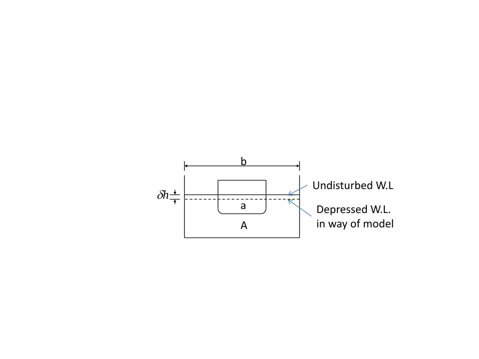
b
a
A
hUndisturbed W.L
Depressed W.L. in way of model
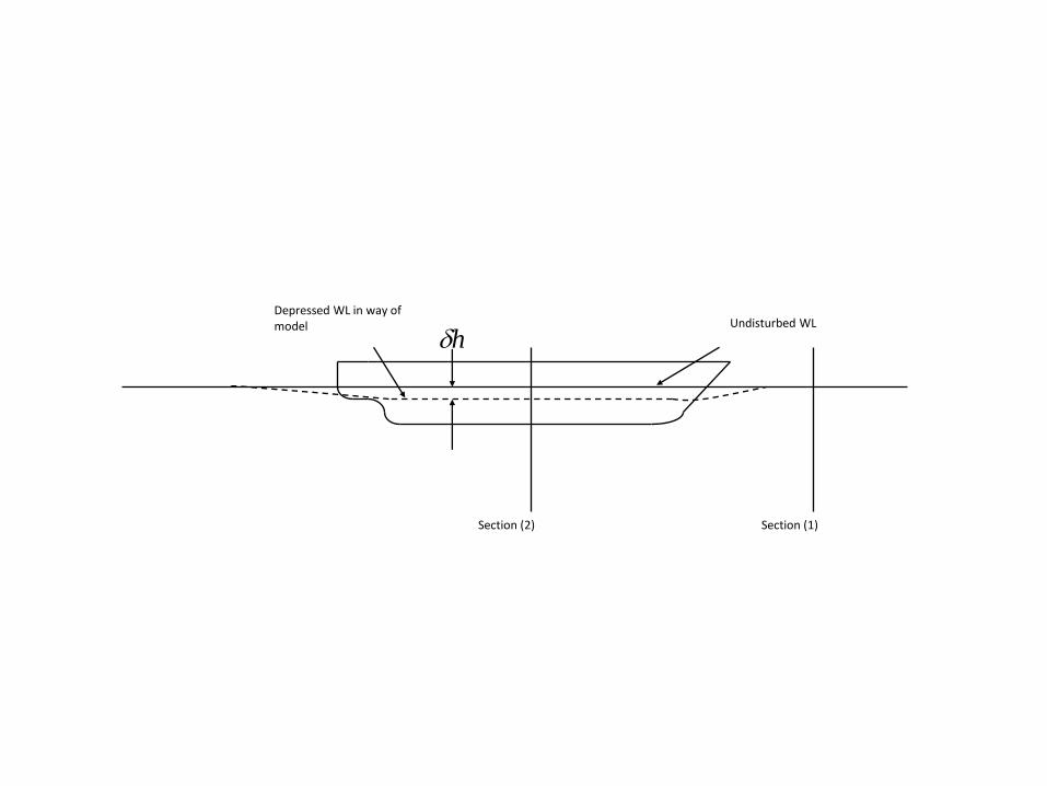
Depressed WL in way of model
Section (1)Section (2)
Undisturbed WL
h
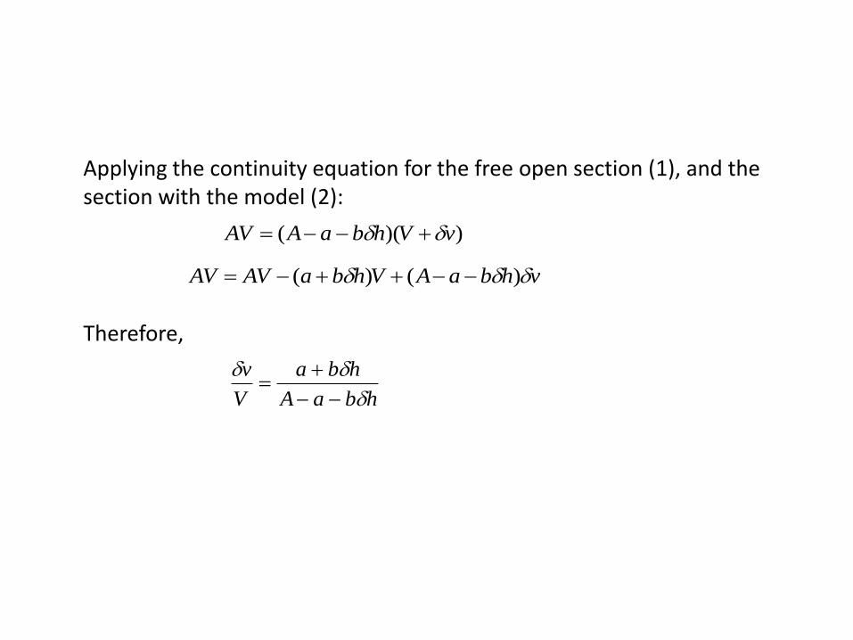
Applying the continuity equation for the free open section (1), and the section with the model (2):
Therefore,
))(( vVhbaAAV
vhbaAVhbaAVAV )()(
hbaA
hba
V
v
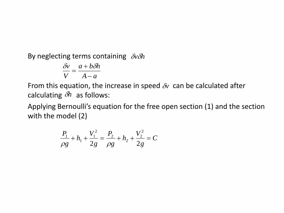
By neglecting terms containing
From this equation, the increase in speed can be calculated after calculating as follows:
Applying Bernoulli’s equation for the free open section (1) and the section with the model (2)
hv
aA
hba
V
v
vh
Cg
Vh
g
P
g
Vh
g
P
22
2
22
2
2
11
1
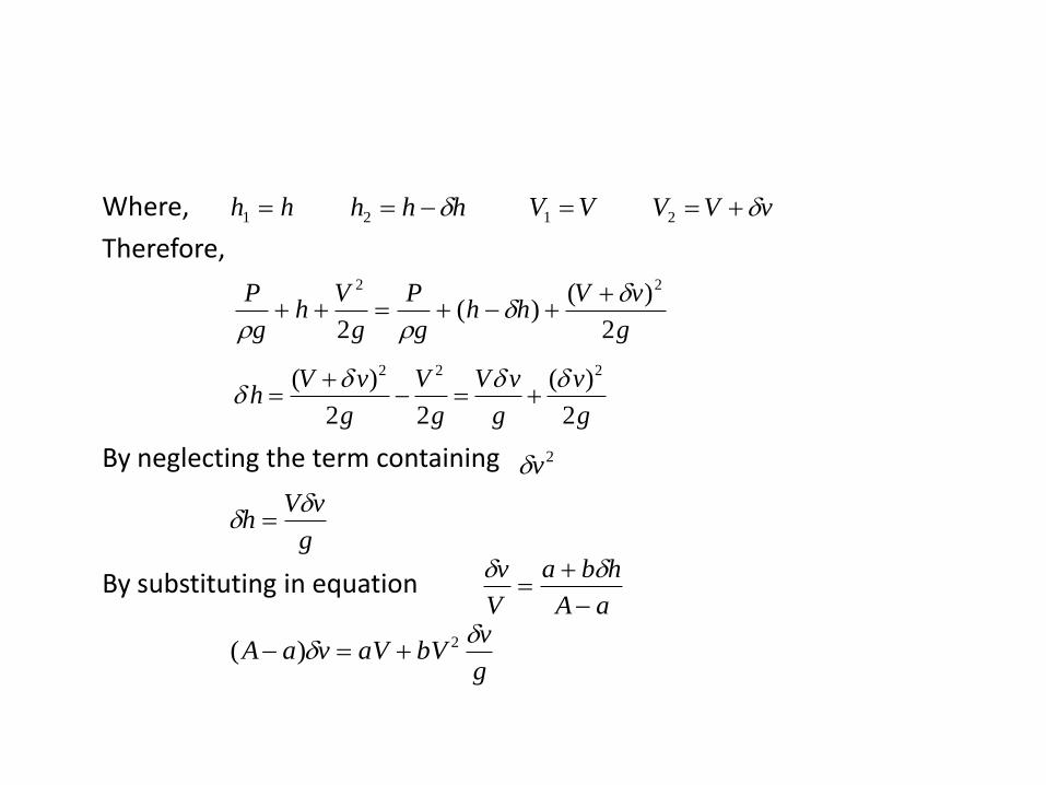
Where,
Therefore,
By neglecting the term containing
By substituting in equation
hh 1 hhh 2 VV 1 vVV 2
g
vVhh
g
P
g
Vh
g
P
2
)()(
2
22
2 2 2( ) ( )
2 2 2
V v V V v vh
g g g g
2v
g
vVh
g
vbVaVvaA
2)(
aA
hba
V
v
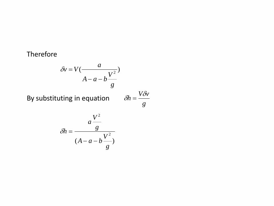
Therefore
By substituting in equation
)(2
g
VbaA
aVv
g
vVh
)(2
2
g
VbaA
g
Va
h
Determination of the ship resistance in shallow waterSchlichting method
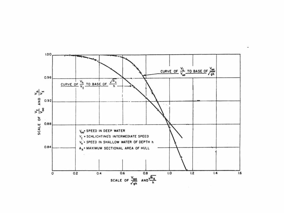
Schlichting performed an analysis on the effects of shallow water on ship resistance. The analysis covered the increase in resistance in shallow water at subcritical speeds, and was for shallow water of unlimited lateral extent.
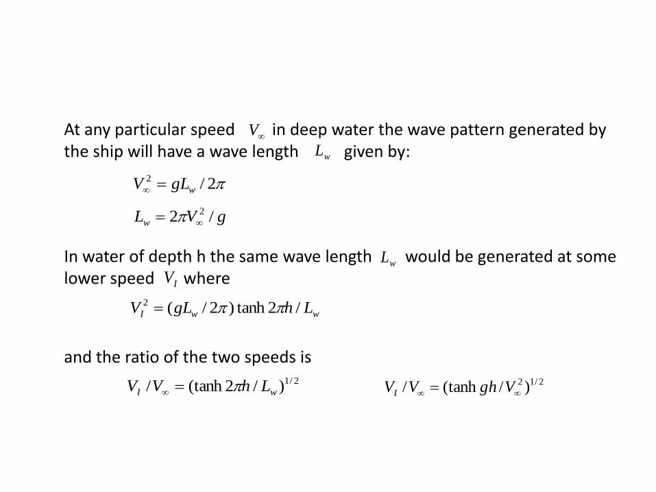
At any particular speed in deep water the wave pattern generated by the ship will have a wave length given by:
In water of depth h the same wave length would be generated at some lower speed where
and the ratio of the two speeds is
V
wL
2/2
wgLV
gVLw /2 2
wL
IV
wwI LhgLV /2tanh)2/(2
2/1)/2(tanh/ wI LhVV 2/12 )/(tanh/ VghVVI
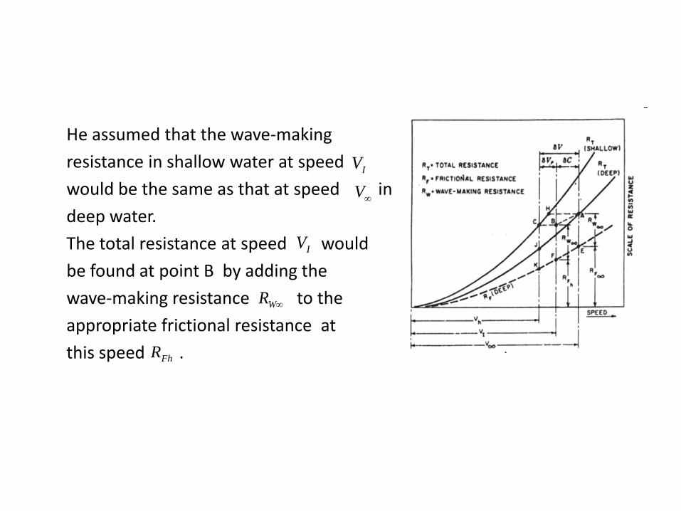
He assumed that the wave-making
resistance in shallow water at speed
would be the same as that at speed in
deep water.
The total resistance at speed would
be found at point B by adding the
wave-making resistance to the
appropriate frictional resistance at
this speed .
IV
V
IV
WR
FhR
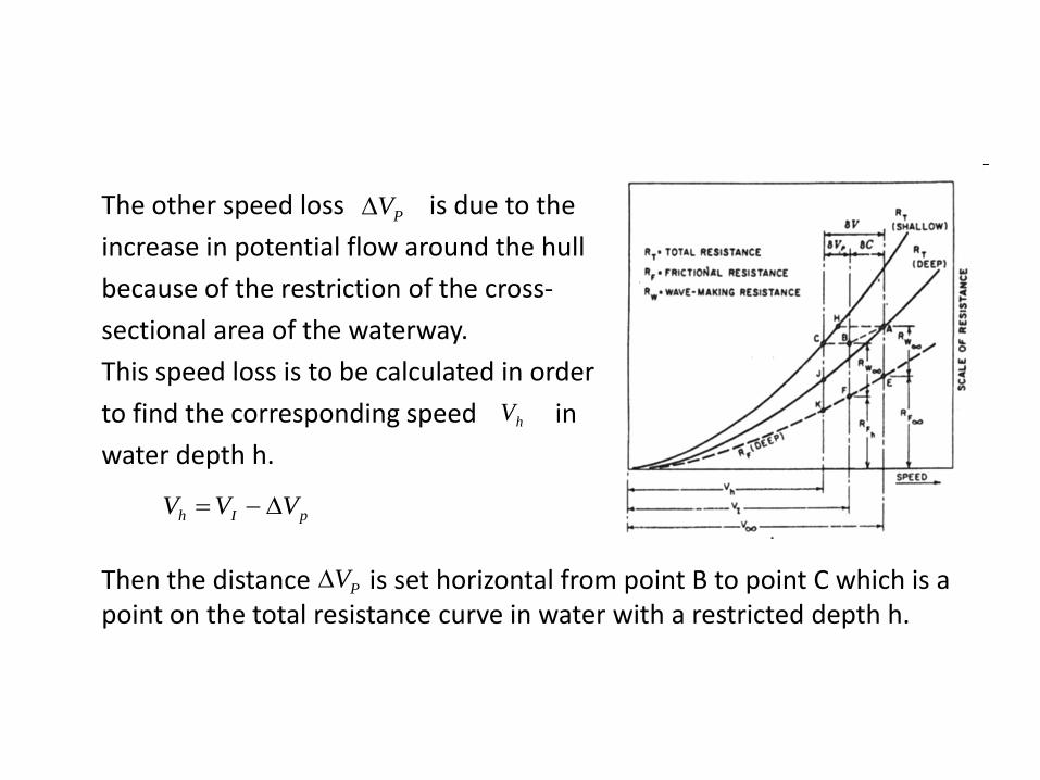
The other speed loss is due to the
increase in potential flow around the hull
because of the restriction of the cross-
sectional area of the waterway.
This speed loss is to be calculated in order
to find the corresponding speed in
water depth h.
Then the distance is set horizontal from point B to point C which is a point on the total resistance curve in water with a restricted depth h.
PV
hV
pIh VVV
PV

Scott method
In this method, Scott estimated the speed of a ship that would have the same resistance in deep water as it would at in water of a restricted depth h
V
hV
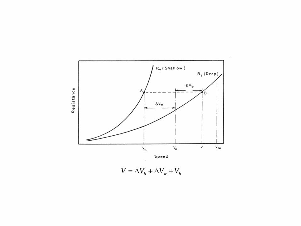
hwb VVVV

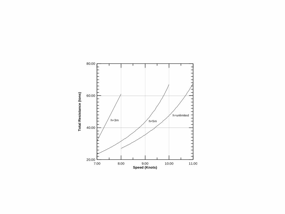
In order to appreciate the increase in resistance in shallow water, the following are the results of some tank testing done on the hull forms for particular Nile floating hotels:
i- Resistance data in tons for LWL = 68.0 m
B = 12.0 m
T = 1.30 m
∆ = 910 tons
7.00 8.00 9.00 10.00 11.00
Speed (Knots)
20.00
40.00
60.00
80.00
To
tal
Re
sis
tan
ce
(to
ns
)
h=3m h=5m
h=unlimited
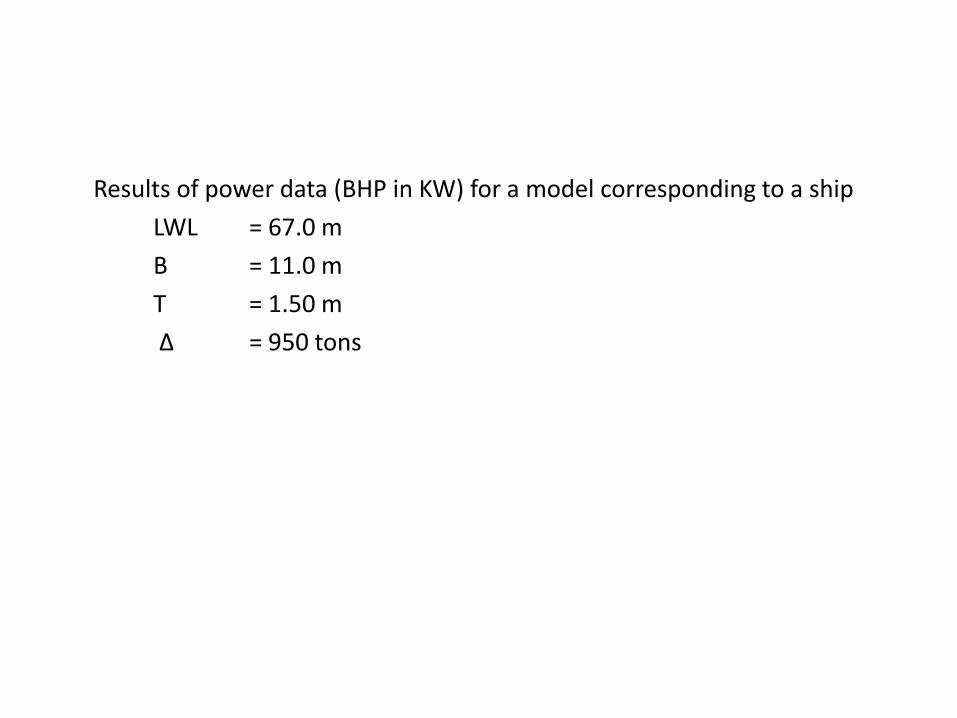
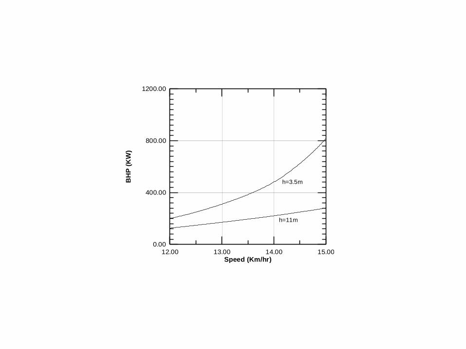
Results of power data (BHP in KW) for a model corresponding to a ship
LWL = 67.0 m
B = 11.0 m
T = 1.50 m
∆ = 950 tons
12.00 13.00 14.00 15.00
Speed (Km/hr)
0.00
400.00
800.00
1200.00
BH
P (
KW
)
h=3.5m
h=11m
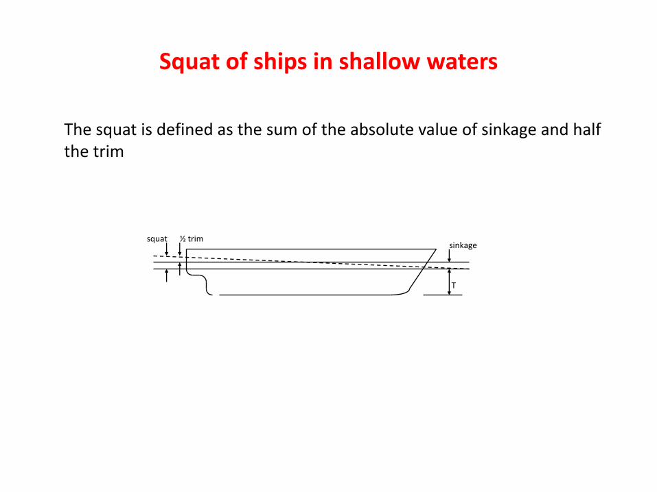
Squat of ships in shallow waters
The squat is defined as the sum of the absolute value of sinkage and half the trim
sinkage
T
½ trimsquat
In shallow water, when the static under-keel clearance is very small, and if a ship moves forward at relatively higher speeds, then grounding could occur at the bow or stern. It may be noted that grounding due to the squat of a ship could be avoided simply by reducing the speed in shallow water
The factors governing ship squat are as follows:
• The speed of the ship, which is considered to be the main factor, as the squat varies approximately with the square of the speed.
• Block coefficient, where squat varies directly with CB.
• The blockage factor, the higher the blockage factor the greater the squat.
• Water depth/ship draft ratio, the smaller the ratio the greater the squat.
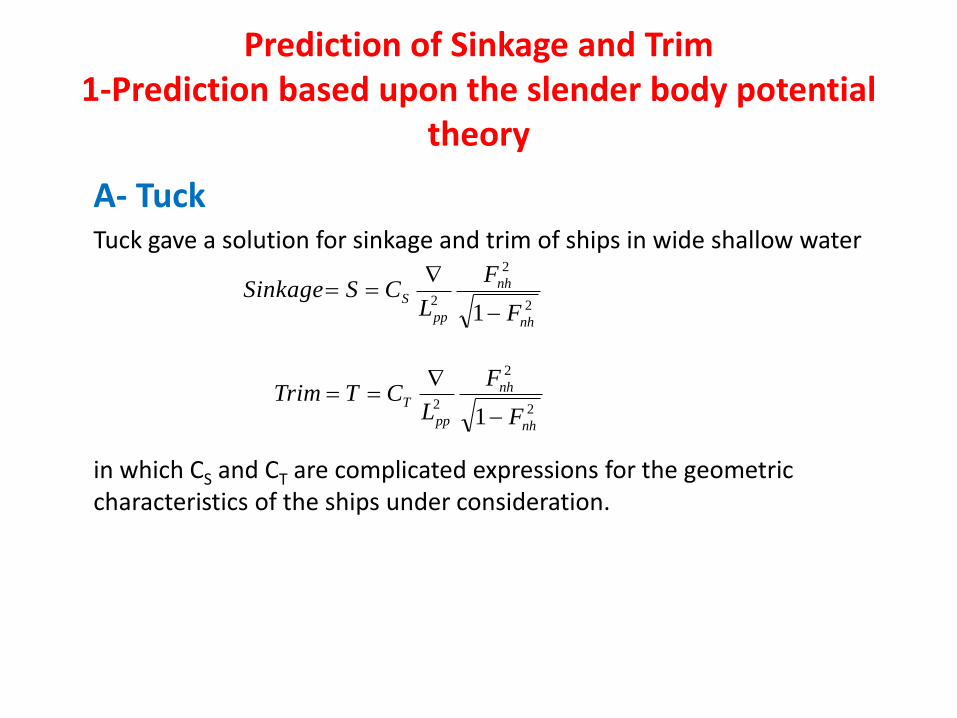
Prediction of Sinkage and Trim1-Prediction based upon the slender body potential
theory
A- TuckTuck gave a solution for sinkage and trim of ships in wide shallow water
in which CS and CT are complicated expressions for the geometric characteristics of the ships under consideration.
2
2
21 nh
nh
pp
S
F
F
LCSSinkage
2
2
21 nh
nh
pp
T
F
F
LCTTrim
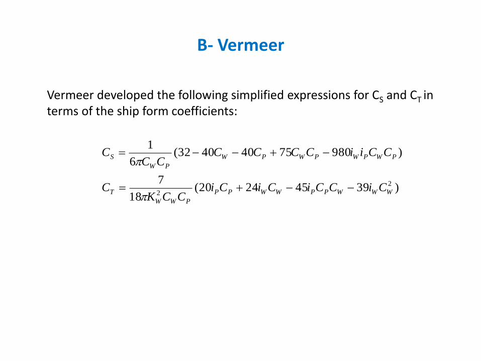
B- Vermeer
Vermeer developed the following simplified expressions for CS and CT in terms of the ship form coefficients:
)39452420(18
7
)98075404032(6
1
2
2 WWWPPWWPP
PWW
T
PWPWPWPW
PW
S
CiCCiCiCiCCK
C
CCiiCCCCCC
C
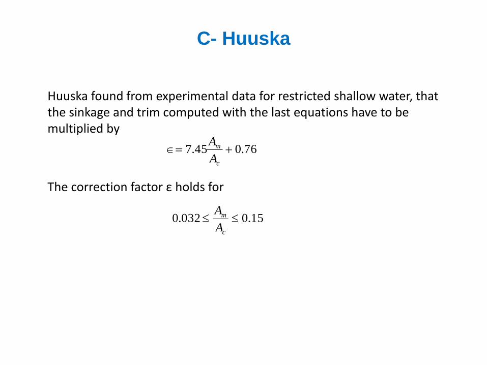
C- Huuska
Huuska found from experimental data for restricted shallow water, that the sinkage and trim computed with the last equations have to be multiplied by
The correction factor ε holds for
76.045.7 c
m
A
A
15.0032.0 c
m
A
A

He also developed another formula for the squat given by
Where, and are shape factors of the ship hull, and the approximate values of these factors are:
2
2
21
)5.0(
nh
nhZ
F
F
LCCSquat
ZCC
0.1
5.1
C
CZ
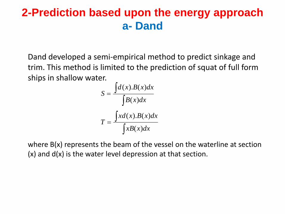
2-Prediction based upon the energy approach
a- Dand
Dand developed a semi-empirical method to predict sinkage and trim. This method is limited to the prediction of squat of full form ships in shallow water.
where B(x) represents the beam of the vessel on the waterline at section (x) and d(x) is the water level depression at that section.
dxxB
dxxBxdS
)(
)().(
dxxxB
dxxBxxdT
)(
)().(
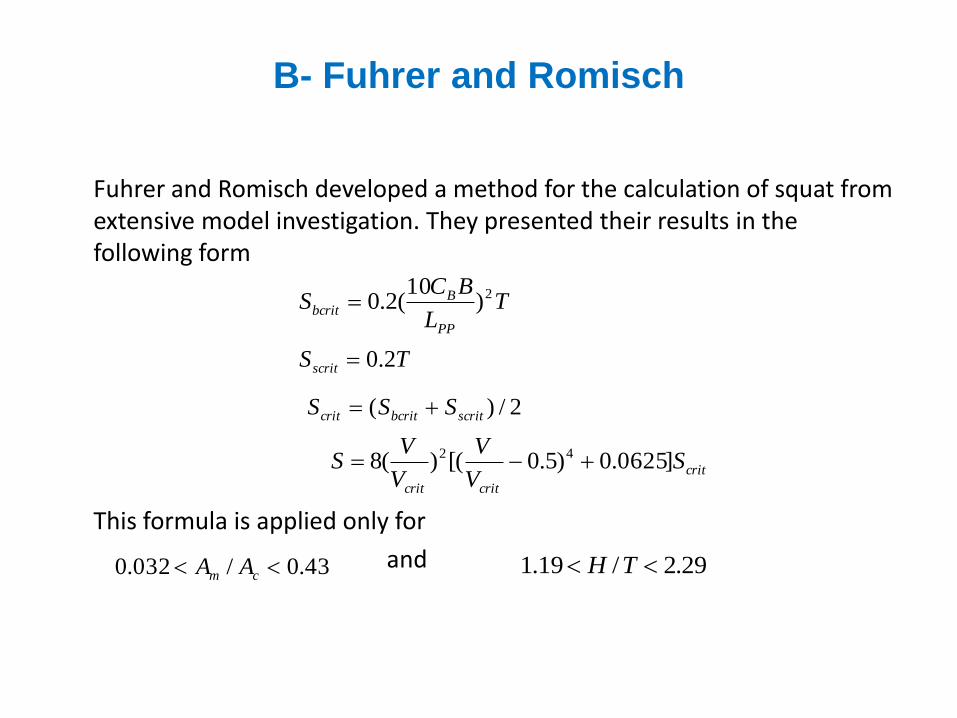
B- Fuhrer and Romisch
Fuhrer and Romisch developed a method for the calculation of squat from extensive model investigation. They presented their results in the following form
This formula is applied only for
and
TL
BCS
PP
Bbcrit
2)10
(2.0
TSscrit 2.0
2/)( scritbcritcrit SSS
crit
critcrit
SV
V
V
VS ]0625.0)5.0[()(8 42
43.0/032.0 cm AA 29.2/19.1 TH
3- Prediction based upon some experimental
methods
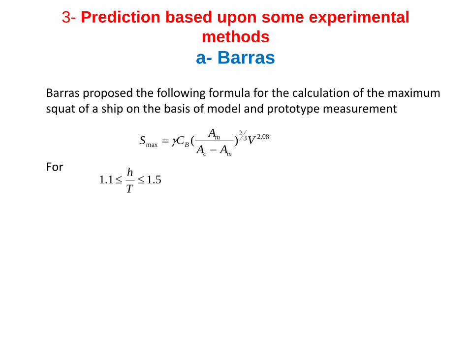
a- Barras
Barras proposed the following formula for the calculation of the maximum squat of a ship on the basis of model and prototype measurement
For
08.232
max )( VAA
ACS
mc
mB
5.11.1 T
h
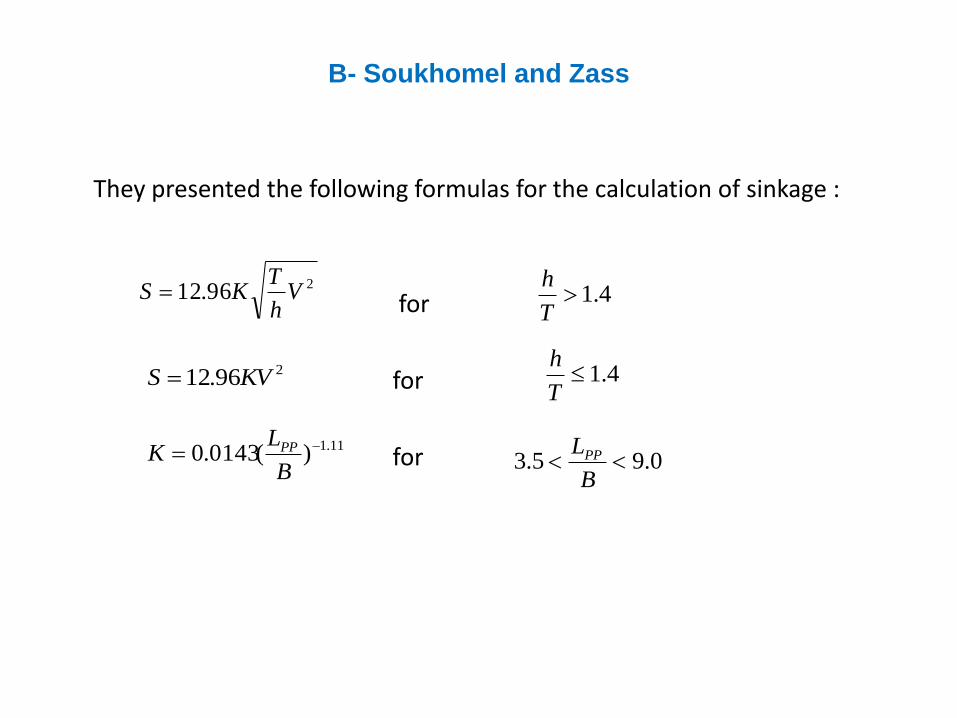
B- Soukhomel and Zass
They presented the following formulas for the calculation of sinkage :
for
for
for
296.12 Vh
TKS 4.1
T
h
296.12 KVS 4.1T
h
11.1)(0143.0 B
LK PP
0.95.3 B
LPP
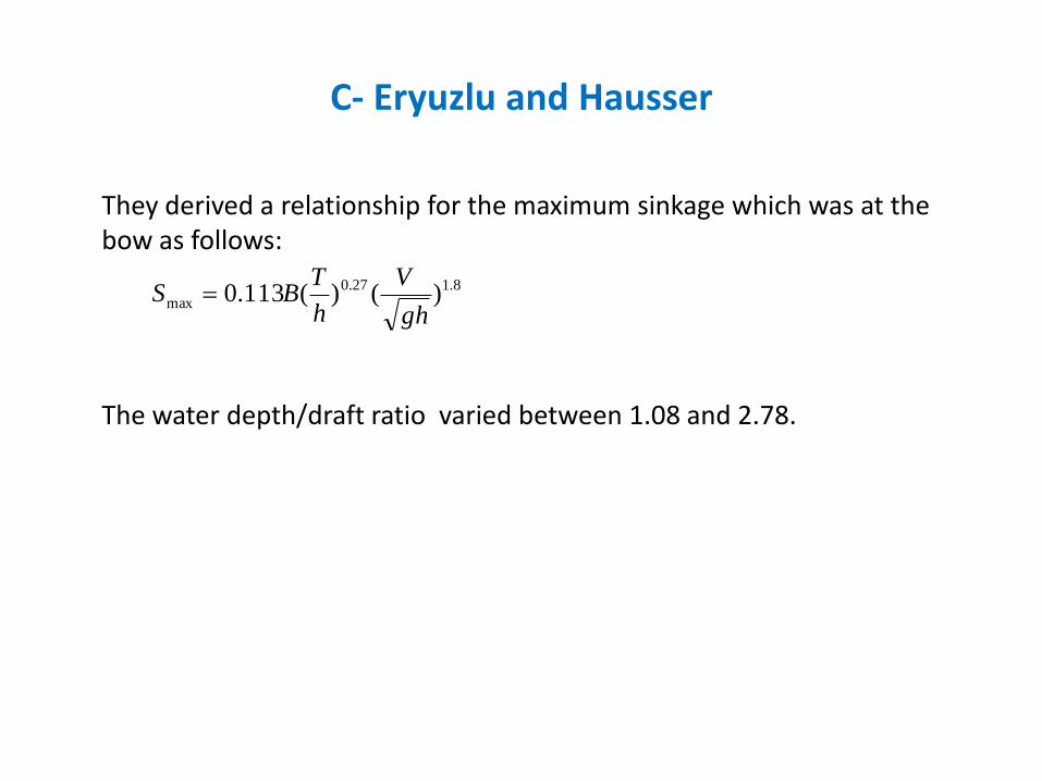
C- Eryuzlu and Hausser
They derived a relationship for the maximum sinkage which was at the bow as follows:
The water depth/draft ratio varied between 1.08 and 2.78.
8.127.0
max )()(113.0gh
V
h
TBS
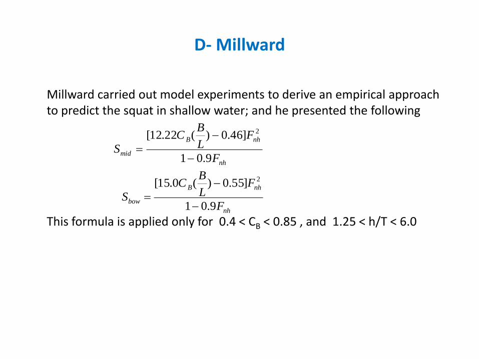
D- Millward
Millward carried out model experiments to derive an empirical approach to predict the squat in shallow water; and he presented the following
This formula is applied only for 0.4 < CB < 0.85 , and 1.25 < h/T < 6.0
nh
nhB
midF
FL
BC
S9.01
]46.0)(22.12[ 2
nh
nhB
bowF
FL
BC
S9.01
]55.0)(0.15[ 2
Estimation of the Limiting Speed in Shallow
Water
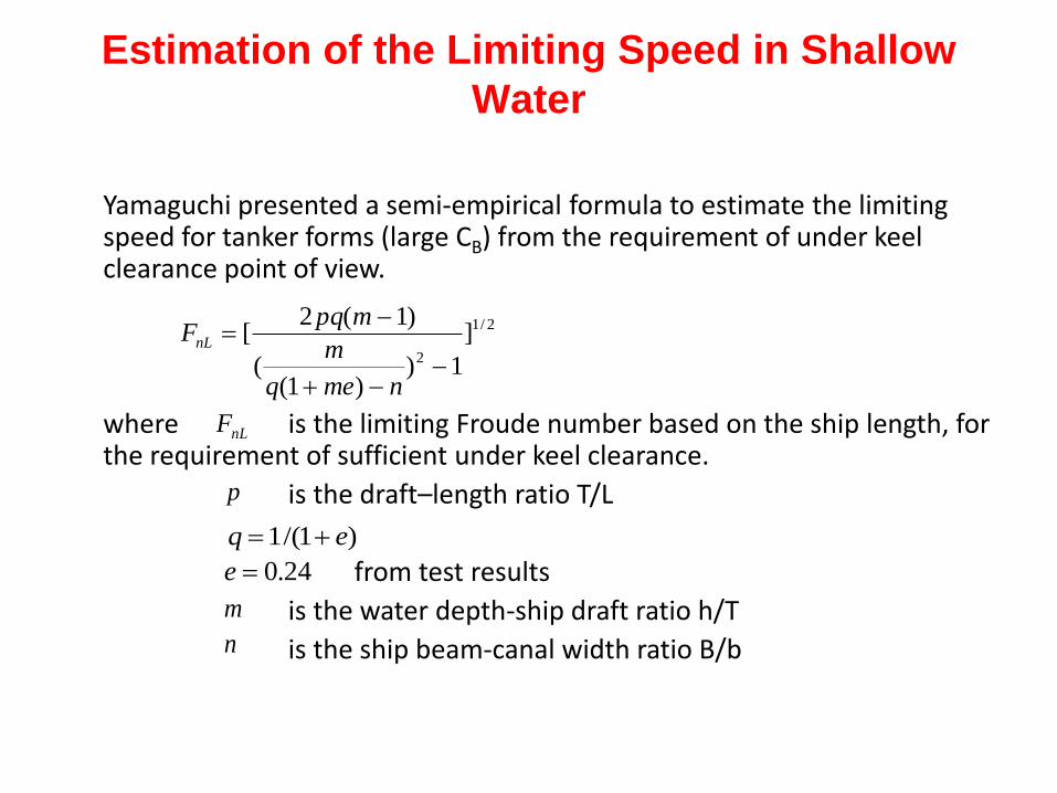
Yamaguchi presented a semi-empirical formula to estimate the limiting speed for tanker forms (large CB) from the requirement of under keel clearance point of view.
where is the limiting Froude number based on the ship length, for the requirement of sufficient under keel clearance.
is the draft–length ratio T/L
from test results
is the water depth-ship draft ratio h/T
is the ship beam-canal width ratio B/b
2/1
2
]
1))1(
(
)1(2[
nmeq
m
mpqFnL
nLF
p
)1/(1 eq
24.0e
m
n