Embed Size (px)
Citation preview

Systemwdesign
1
VehicleMode
2
DaytimeRunningLights
DippedBeam
VehicleMode
AutoHeadlightSwitching
1
2
DippedBeamAutoHeadlightSwitching
DaytimeRunningLights
Verificationwsubsystem
Model-Based Testing with Simulink Design Verifier
A case study on property proving and automatic test casegeneration for automotive embedded systems
Master’s thesis
Marcus Liliegard
Viktor Nilsson
Department of Signals and SystemsCHALMERS UNIVERSITY OF TECHNOLOGYGoteborg, Sweden 2014

REPORT NO. EX02b/2014
Model-Based Testing with SimulinkDesign Verifier
A case study on property proving and automatic test case generationfor automotive embedded systems
MARCUS LILIEGARDVIKTOR NILSSON
Department of Signals and SystemsChalmers University of Technology
Goteborg, Sweden 2014

Model-Based Testing with Simulink Design VerifierA case study on property proving and automatic test case generation for automotiveembedded systemsMARCUS LILIEGARDVIKTOR NILSSON
©MARCUS LILIEGARD, VIKTOR NILSSON, 2014.
Technical report no EX02b/2014Department of Signals and SystemsChalmers University of TechnologySE-412 96 GoteborgSweden
Cover:A Simulinkr model with a system design model and a verification subsystem.
Chalmers University of TechnologyGoteborg, Sweden 2014

“Testing is the process of systematically experimenting with an object in order todetect failures, measure its quality, or create confidence in its correctness.”- Stephan Weileder and Holger Schlingloff

Abstract
The amount of features in vehicles is rapidly increasing. Today the self-driving car isno longer a futuristic vision, but instead a highly tangible reality. To achieve a highproduct quality without errors, for a complex system, efficient testing methods areneeded. The purpose of this thesis is to investigate how the Model-Based Testing(MBT) tool Simulinkr Design Verifier� can be applied to solve problems regardingerror detection, automation and possibilities for earlier testing. Three methods formodeling requirements and applying MBT are considered: property proving withproof objectives; automatic test case generation with cause-effect graphs and testobjectives.
The research questions of the thesis covers: (i) the types of software requirements foran embedded system, (ii) how to model these according to the three MBT methods,(iii) which method that is most appropriate to use for each type.
To answer these questions a case study was performed. The case covered the exteriorlights of a truck, where focus was put on Automatic Headlight Switching. The casewas selected mainly due to its appropriate complexity level. However, no automaticcontrol was part of the system, which limits the applicability of the results.
Based on the case study answers to the research questions are provided. First re-quirements are grouped into three main types and a classification of the functionalrequirements, based on temporal properties and modeling similarities, is introduced.Secondly, models of each requirement type, based on the three methods , are de-scribed in detail. Lastly, an appropriate method for each requirement type is pre-sented, based on an analysis regarding model complexity, applicability for differenttest systems and error detectability.
The analysis regarding appropriate methods puts emphasis on the functional re-quirements, since these were the only main type where MBT could be applied. Forthe case study it was found that requirements describing undesired behavior aresuitable to verify with property proving. Test objectives were only useful for onesmall type of functional requirements that describes when a function shall be pos-sible to activate. For the other functional requirements, test case generation withcause-effect graphs is recommended, due to the possible application on different testsystems.
MBT can help find requirement errors since requirements are modeled in a formalmanner. Testing can also start early since the models can be created during therequirement writing. When selecting an appropriate MBT method it is useful toanalyze the requirements and behavior of the System Under Test.
i

ii
Keywords: Model-Based Testing, Simulink, Simulink Design Verifier, propertyproving, automatic test case generation, cause-effect graphs.

Preface
This thesis was conducted as the completion of the Masters Program Systems Con-trol and Mechatronics at Chalmers University of Technology. The thesis work wasintended for and supervised by the Test and Development department at InfotivAB. The actual case study was carried out at Volvo Group Trucks Technology.
Author contributions
Marcus Liliegard has contributed to the following chapters: Model Based Testing,Simulink Design Verifier, Modeling requirements for use with Model-Based Testingand Conclusions.
Viktor Nilsson has contributed to the following chapters: Introduction, Testing atVolvo GTT, The case study, Requirement types of an automotive embedded systemand Evaluation of Model-Based Testing methods.
Acknowledgments
We would like to thank our examiner Knut Akesson for his support in developingour idea about the thesis and also for his feedback and opinions on the content ofthis report.
We would like to acknowledge Dan Olsson, our supervisor at Infotiv, for his supportand guidance. We also thank Peter Thorngren, our supervisor at Volvo, for hiscontribution in enabling this thesis project and his enthusiasm during our work.
We also appreciate the help from others at Infotiv, especially Tomas Sjogren, PeterHaglund, Tariq Khalaili and Kristoffer Abrahamsson. The support from variouspeople of the Integration and Verification section and especially Pierre Lange, wasalso highly appreciated.
Finally we thank the people at The MathWorks and especially Fredrik Olsson forenabling this thesis by providing the necessary software.
Goteborg, July 1, 2014
Marcus Liliegard, Viktor Nilsson
iii


Contents
Abbreviations 1
1 INTRODUCTION 3
1.1 Background . . . . . . . . . . . . . . . . . . . . . . . . . . . . . . . . . . . . . . . . . . . . . . . . . . 3
1.2 Research questions . . . . . . . . . . . . . . . . . . . . . . . . . . . . . . . . . . . . . . . . . . . . 4
1.3 Scope and Limitations . . . . . . . . . . . . . . . . . . . . . . . . . . . . . . . . . . . . . . . . . . 6
1.4 Outline . . . . . . . . . . . . . . . . . . . . . . . . . . . . . . . . . . . . . . . . . . . . . . . . . . . . . . 6
2 TESTING AT VOLVO GTT 9
2.1 Testing process . . . . . . . . . . . . . . . . . . . . . . . . . . . . . . . . . . . . . . . . . . . . . . . 9
2.2 Test systems . . . . . . . . . . . . . . . . . . . . . . . . . . . . . . . . . . . . . . . . . . . . . . . . . 11
2.3 Problem areas . . . . . . . . . . . . . . . . . . . . . . . . . . . . . . . . . . . . . . . . . . . . . . . . 13
2.4 Summary . . . . . . . . . . . . . . . . . . . . . . . . . . . . . . . . . . . . . . . . . . . . . . . . . . . . 13
3 MODEL-BASED TESTING 15
3.1 The Fundamentals of Model-Based Testing . . . . . . . . . . . . . . . . . . . . . . . . 15
3.2 Possibilities for improvements . . . . . . . . . . . . . . . . . . . . . . . . . . . . . . . . . . . . 16
3.3 Tools for Model-Based Testing . . . . . . . . . . . . . . . . . . . . . . . . . . . . . . . . . . . 16
3.4 Related work . . . . . . . . . . . . . . . . . . . . . . . . . . . . . . . . . . . . . . . . . . . . . . . . . 17
3.5 Requirement specifications . . . . . . . . . . . . . . . . . . . . . . . . . . . . . . . . . . . . . . 18
3.6 Summary . . . . . . . . . . . . . . . . . . . . . . . . . . . . . . . . . . . . . . . . . . . . . . . . . . . . 19
4 SIMULINK DESIGN VERIFIER 21
4.1 Features and Fundamentals . . . . . . . . . . . . . . . . . . . . . . . . . . . . . . . . . . . . . 21
4.2 Modeling requirements . . . . . . . . . . . . . . . . . . . . . . . . . . . . . . . . . . . . . . . . . 25
4.2.1 Proof objective models . . . . . . . . . . . . . . . . . . . . . . . . . . . . . . . . . . . 25
v

4.2.2 Test objective models . . . . . . . . . . . . . . . . . . . . . . . . . . . . . . . . . . . . 26
4.2.3 Cause-effect graphs . . . . . . . . . . . . . . . . . . . . . . . . . . . . . . . . . . . . . . 27
4.3 Summary . . . . . . . . . . . . . . . . . . . . . . . . . . . . . . . . . . . . . . . . . . . . . . . . . . . . 29
5 THE CASE STUDY 31
5.1 Case selection . . . . . . . . . . . . . . . . . . . . . . . . . . . . . . . . . . . . . . . . . . . . . . . . 31
5.2 The system for Automatic Headlight Switching . . . . . . . . . . . . . . . . . . . . . 31
5.3 Specification of the system . . . . . . . . . . . . . . . . . . . . . . . . . . . . . . . . . . . . . . 33
5.4 Existing Simulink model . . . . . . . . . . . . . . . . . . . . . . . . . . . . . . . . . . . . . . . . 34
5.5 Limitations . . . . . . . . . . . . . . . . . . . . . . . . . . . . . . . . . . . . . . . . . . . . . . . . . . . 35
5.6 Summary . . . . . . . . . . . . . . . . . . . . . . . . . . . . . . . . . . . . . . . . . . . . . . . . . . . . 36
6 REQUIREMENT TYPES OF AN AUTOMOTIVE EMBEDDED SYS-TEM 37
6.1 Identified requirement types . . . . . . . . . . . . . . . . . . . . . . . . . . . . . . . . . . . . . 37
6.2 Description of requirement types . . . . . . . . . . . . . . . . . . . . . . . . . . . . . . . . . 38
6.3 Common requirements . . . . . . . . . . . . . . . . . . . . . . . . . . . . . . . . . . . . . . . . . 41
6.4 Discussion . . . . . . . . . . . . . . . . . . . . . . . . . . . . . . . . . . . . . . . . . . . . . . . . . . . 42
6.5 Summary . . . . . . . . . . . . . . . . . . . . . . . . . . . . . . . . . . . . . . . . . . . . . . . . . . . . 42
7 MODELING REQUIREMENTS FOR USEWITHMODEL-BASED TEST-ING 43
7.1 Proof objective models . . . . . . . . . . . . . . . . . . . . . . . . . . . . . . . . . . . . . . . . . 43
7.2 Test objective models . . . . . . . . . . . . . . . . . . . . . . . . . . . . . . . . . . . . . . . . . . 48
7.3 Cause-effect graphs . . . . . . . . . . . . . . . . . . . . . . . . . . . . . . . . . . . . . . . . . . . . 50
7.4 Discussion . . . . . . . . . . . . . . . . . . . . . . . . . . . . . . . . . . . . . . . . . . . . . . . . . . . 55
7.5 Summary . . . . . . . . . . . . . . . . . . . . . . . . . . . . . . . . . . . . . . . . . . . . . . . . . . . . 56
8 EVALUATION OF MODEL-BASED TESTING METHODS 57
8.1 Applicability . . . . . . . . . . . . . . . . . . . . . . . . . . . . . . . . . . . . . . . . . . . . . . . . . . 58
vi

8.2 Model complexity and scalability . . . . . . . . . . . . . . . . . . . . . . . . . . . . . . . . . 60
8.3 Error detectability . . . . . . . . . . . . . . . . . . . . . . . . . . . . . . . . . . . . . . . . . . . . . 61
8.4 Evaluation . . . . . . . . . . . . . . . . . . . . . . . . . . . . . . . . . . . . . . . . . . . . . . . . . . . 63
8.5 Discussion . . . . . . . . . . . . . . . . . . . . . . . . . . . . . . . . . . . . . . . . . . . . . . . . . . . 64
8.6 Summary . . . . . . . . . . . . . . . . . . . . . . . . . . . . . . . . . . . . . . . . . . . . . . . . . . . . 65
9 CONCLUSION 67
9.1 Improving the development process with Model-Based Testing . . . . . . . . . 67
9.2 Raised questions . . . . . . . . . . . . . . . . . . . . . . . . . . . . . . . . . . . . . . . . . . . . . . 68
Bibliography 71
APPENDIX 75
A Modeling guidelines 75
B Systematic test case generation 77
vii
List of Abbreviations
AHS Automatic Headlight Switching
DRL Daytime Running Lights
E2E End-to-End
E2EF End-to-End Function
ECU Electronic Control unit
FRS Functional Requirement Specification
HiL Hardware-In-the-Loop
HMI Human-Machine Interface
I/O Input/Output
LCP Light Control Panel
LDC Logical Design Component
MBD Model-Based Design
MBT Model-Based Testing
MCDC Modified Condition/Decision Coverage
MiL Model-In-the-Loop
SiL Software-In-the-Loop
SLDV Simulinkr Design Verifier�
SUT System Under Test
VMCU Vehicle Master Control Unit
Volvo GTT Volvo Group Trucks Technology
1

2
1 INTRODUCTION
Vehicles are becoming increasingly automated and complex to meet the require-ments of everything from customer needs to environmental laws. Due to thisthe automotive industry is integrating more and more software into its products(Hanselmann 2008). The cost for developing an electric and electronic system canbecome one-third of the total development costs (Weber and Weisbrod 2003). It isdesired that the final product contains little or no software errors, especially with ad-vanced safety critical functionality, such as self-driving cars (Volvo Car Group 2013),(Gibbs 2014).
1.1 Background
With the increasing software complexity the number of requirement specificationsincreases. A problem will arise when specifications are not clear enough and the de-velopers, who might be separated in many ways from the requirement writer, haveto make guesses about how the system shall function. These guesses can lead to un-intended behavior and errors, which can result in problems later in the developmentprocess. These issues especially occur when the software is being integrated in thecomplete system and tested with parts from other developers.
Finding and fixing a requirement error at the design phase can cost three to eighttimes more than correcting it at the requirement writing phase (Stecklein et al. 2004).Instead finding the error as late as the system test and integration phase can costaround 20 to 70 times more than it would cost to fix it at the writing phase (Steckleinet al. 2004). Thus to be able to develop complex products and maintain the controlover costs, it is necessary to find errors as early as possible in the development process(Zander et al. 2011, p. 551). When requirements are correct it is also desired to verifythese at an early stage to be able to correct design errors. To reduce costs anddevelopment time further it is desirable to perform the verification in an efficientmanner. The methods and processes used must also be able to handle productchanges during the development.
To help solving these problems of the development process the concepts of Model-Based Testing (MBT) (Apfelbaum and Doyle 1997), (Zander et al. 2011, p. 549),(The MathWorks Inc 2014) and Model-Based Design (MBD) (Friedman 2006) canbe used. MBD involves creating a system design model and using this for simula-tions, early testing and code generation. A feature of MBT is automatic generationof test cases based on a model of the system behavior. This can help finding contra-dictory specifications to a higher extent than manual tests (Pretschner et al. 2005).Automatic test case generation is also cost efficient, compared to manual test writing(Utting et al. 2007, ch. 2).
3

4 Chapter 1 Introduction
Another MBT feature is property proving, where a model of requirements is usedtogether with a system design model to prove that the requirements are alwaysfulfilled (The MathWorks Inc 2014).
By combining MBD and MBT the verification of an embedded system can startearly during the development, since no hardware is required. The combination ofMBD with extensive early testing increases the number of errors found compared toonly using models for design purposes (Broy et al. 2012). To summarize, MBT is atopic that shows possibilities for improving the development process and thereforemake it possible to maintain control over costs and time consumption when creatingan automotive embedded system.
1.2 Research questions
The purpose of this thesis is to investigate how MBT can be used to improve thedevelopment process for an automotive embedded system, and that this can benefitfrom making connections to the types of system behavior and requirements.
The objectives of the thesis are to evaluate possibilities for improvement concerning:
1. Finding errors such as:
(a) Requirement errors such as unclear, incomplete or contradictory require-ments.
(b) Implementation errors resulting in violation of requirements.
2. Automation of the processes regarding:
(a) Creation of test cases that covers a group of requirements, a single re-quirement or specified part of a requirement.
(b) Creation of executable test scripts.
3. Initiating the testing earlier in the development process, regarding:
(a) Creation of both abstract and detailed low level tests.
(b) Testing on multiple test systems used in different phases of the develop-ment process.
(c) Reusing information from a previous development process

1.2 Research questions 5
The purpose and objectives form the basis for the following research questions whichthis thesis will answer:
� What types of software requirements exist for an automotive embedded systemand which are most common?
� How can these requirements be modeled for use with different MBT methodsin the MBT tool Simulinkr Design Verifier� (SLDV)?
� Which MBT method is the most appropriate for each requirement type?
– At which system levels and test systems can the different methods beapplied?
– How well does the requirement models scale with respect to increasednumber of input signals and requirement complexity?
– What types of errors can be detected with the different methods?
The MBT methods considered are: property proving with proof objective models;automatic test case generation with test objective models and cause-effect graphs.These will be described in detail in Chapter 4.
To answer these questions and gather the necessary data a case study together withan initial literature review was chosen as method. This enabled acquiring data froma real project and therefore take different anomalies, such as unclear requirements,into account. The case study, presented in Chapter 5, was performed at the Integra-tion and Verification section of the Electronics and Electrics department at VolvoGroup Trucks Technology (Volvo GTT). The specific case was chosen due to an al-ready existing system model that enabled focus on MBT. It also consisted of severalsubsystems which allowed a more industrial workflow consisting of both componentand system verification.
The approach in this thesis is as follows:
1. Analyze the requirements of an automotive embedded system and group theseinto types that are relevant for modeling with the considered MBT methods.
2. Model requirements of each identified type, for each of the MBT methods andidentify factors in the requirement formulation that simplifies the modelingprocess.
3. Apply the corresponding SLDV feature to the modeled requirements and ex-plore the tool.
4. Analyze the modeling and application by addressing factors relevant to prob-lems that exist in an industrial context.

6 Chapter 1 Introduction
1.3 Scope and Limitations
The scope of the thesis is the MBT tool SLDV and its features property provingand automatic test case generation. The selection of this one tool was made forpractical reasons. A relation with the supplier of SLDV (The MathWorks Inc) wasalready established thus making it possible to use the software necessary for theinvestigation of MBT. The existing system model was built in Simulinkr and bychoosing SLDV as the MBT tool no translation of the system model was needed.
Including software configuration parameters when applying property proving andgenerating test cases was also considered within the scope, due to its relevancy forthe studied case. A limitation has still been made to only consider one vehiclevariant configuration during the case study. The reason for this was to cope withthe limited time and be able to produce reliable results about modeling differenttypes of requirements. However, since there exists support for handling variants inSimulinkr future research could possibly cover this gap.
There also exists limitations about in which types of test systems the generatedtest cases can be applied. Since only Model-In-the-Loop (MiL) tests are performedno data about executing the tests in other environments, such as Software-In-the-Loop (SiL) or Hardware-In-the-Loop (HiL), could be obtained. This area couldbe covered by constructing an algorithm to create executable test scripts from thegenerated test cases or by running a model containing the test cases inside a testingenvironment.
Simulinkr blocks incompatible with SLDV is not considered within the scope. Thisimplies limitations about continuous time behavior, since this is an unsupportedfeature. By not considering more modeling methods there exists further limitations.This only affects the results regarding the evaluation of MBT methods, the types ofrequirements and how to model those are still valuable results.
1.4 Outline
The proper background for the case is presented in Chapter 2. Here the currenttesting process at Volvo GTT is described, together with the different existing testsystems. Current problem areas are also indicated. After this, the methodologyfor Model-Based Testing is described in Chapter 3. Connections are made to MBDwhich is a necessary part for two of the MBT methods.
When the current testing process and the basics of MBT are explained, possibilitiesfor conquering the problem areas by using MBT are presented in Section 3.2. Thefollowing section introduces other available MBT tools and briefly compares thoseto SLDV. Related work is then presented to position the thesis and explain thecontributions it will make. Lastly, theory about requirements is introduced to forma foundation for answering the research question about requirement types.

1.4 Outline 7
Chapter 4 describes the tool Simulinkr Design Verifier� and its available featuresto understand how it is used. In the last section general modeling techniques forthe methods are explained and illustrated.
After the theoretical foundation is established Chapter 5 introduces the case andexplains how it was selected. To later understand the results about requirementtypes the main functionality is described. The system specifications at differentlevels are also introduced. The components that implement the functionality areexplained and connected to the system specification. The limitations of the caseare also presented in this chapter, to give an indication of where the results areapplicable or might be inaccurate.
For each of the research questions a result is presented and discussed. Startingwith Chapter 6: Requirement types of an automotive embedded system, where theidentified types are presented together with how they are distributed. The effectof requirement formulation is discussed together with how well the analyzed systemrepresents the average embedded system.
Chapter 7: Modeling requirements for use with Model-Based Testing, explains howeach requirement type is modeled as proof objective, test objective and cause-effectgraph respectively. Lastly Chapter 8 evaluates the three MBT methods and anappropriate method for each requirement type are presented and motivated.
Finally conclusions are made about the usefulness of the selected approach and MBTin general. Connections are also made to the conclusions of related research. Raisedquestions which could be the base for future work are also presented.

8 Chapter 1 Introduction

2 TESTING AT VOLVO GTT
At the Integration and Verification section of the Electronics and Electrics depart-ment complete system test are designed and executed. Here the software of thevehicle is the focus for the tests. Testing is also carried out at other groups, e.g. thePowertrain group, and at other levels, e.g. testing of individual software componentsor Electronic Control units (ECUs). Due to the case study being carried out at theIntegration and Verification group this thesis and chapter will consider the testingperformed there. This chapter only provides the details necessary for the thesis, inreality the process is far more complex.
2.1 Testing process
The tests are performed at two phases, integration and verification. The main goalfor the integration phase is to make sure that the test system is operable for theverification phase, which tests the different system level functions. Both phasesincludes planning, development and execution of tests. An overview of the processis shown in Figure 2.1.
Figure 2.1. Overview of the system level testing at Volvo GTT, showing the twophases, integration and verification, together with the information inputs.
The integration phase includes checking that it is possible to download softwareto the ECUs and that the communication is working properly. The main vehiclefunctionality is also tested, for example engine start and braking.
9

10 Chapter 2 Testing at Volvo GTT
Based on the changes in the tested software, which can be new functionality, bugfixes or changed hardware, strategic test cases are selected to address these mattersspecifically. The tests are also adapted based on the test system and also the vehiclevariant, which can be for example different equipment levels.
When the test system is considered operable the verification phase starts. The goalof this phase is to verify end user functionality, which consists of the whole chainfrom user input to system output. For example, to verify part of the main beamheadlights a test is executed where the vehicle is put in a running state, lights areactivated and the main beam stalk is pulled to check that the lights are activated.
To create a functional test case information from use cases and scenarios, whichhave a high abstraction level, are used. To determine which actual signals thatshall be part of the test a sequence diagram is used. The sequence diagram connectsscenarios and use cases to signals that are present in the system. All this informationis stored in a database and accessed via a SystemWeaver platform called SETool1.
If extra details are needed for the test case, lower level specifications, describing theunderlying software components, are used as the source of information. The testcases are also adapted based on the test system which it will execute on.
All gathered information is used to manually create a test script using the softwarePNTool2. The script describes which input signals that shall be set and whichoutput signals that shall be read. The outputs are also compared to the expectedvalues. Timing can be checked at this stage, by including a waiting time for thecomparison. A test script for verifying a part of the main beam headlight’s behaviorcan be seen in Figure 2.2.
Figure 2.2. Example of a test script in PNTool. The script first sets the vehiclein a state where the engine is about to start. Then the signal for the main beamstalk is set to neutral. A check is performed to verify that the signal for the mainbeam is set to off. Finally the output from the corresponding ECU is checked.
The tests in both the integration and verification phases are executed on several testsystems that are described in the following section.
1http://systemite.se/content/products-services/systemweaver-platform2PNTool is developed by Volvo

2.2 Test systems 11
2.2 Test systems
There are three types of test systems for the system level tests, Hardware-In-the-Loop (HiL) rigs, Box trucks and Complete vehicle rigs. Many of the tests are carriedout at HiL rigs, which contain most of the real hardware but simulates the physicalvehicle movement and sensor inputs.
The hardware included in a HiL rig are: the complete Human-Machine Interface(HMI) consisting of buttons, stalks, dashboard, indicator lamps and various displays;the lights, both interior and exterior; selected parts of the pneumatic system; allECUs that are not part of the powertrain.
A CANoe3 testing environment, running on a PC, is connected to the rig. Thisenvironment can observe signals in the system via a CAN-bus interface4. The in-puts from the hardware can also be sent via this interface instead of applying theinputs manually (with stalks and buttons, etc.). The testing environment allowsautomatic execution of tests by applying inputs and monitoring outputs accordingto the written test script. Figure 2.35 shows a HiL test rig where system tests areperformed.
Figure 2.3. Photo of a HiL test system at Volvo GTT. The HMI is shown tothe left, monitors displaying the testing environment to the right. The rigs forsimulation and signal monitoring are located in the background to the right.
3http://vector.com/vi_canoe_en.html4http://www.bosch-semiconductors.de/media/pdf_1/canliteratur/can_fd_spec.pdf5Source: Volvo Group Trucks Technology

12 Chapter 2 Testing at Volvo GTT
Simulating parts of the vehicle allows efficient testing of different vehicle variantsin terms of models, equipment, number of axles, etc. It is also possible to testfailure handling behavior and robustness, since errors such as short circuits anddisconnection of components can easily be introduced. Since the truck body issimulated dynamic and safety critical tests can be executed in the HiL test rig aswell. For example, running a test that disconnects the ECU responsible for brakingwhile the vehicle is running 90 km/h and making an evasive maneuver, is easilydone in the test rig but is unsafe to test with a real vehicle. All the features forsimulation and fault injection can be part of a test script to allow for automation.
The goal is to automatically execute most of the HiL tests, but currently semi-automated and manual tests are also used. When running manual tests, test en-gineers will perform input actions and evaluate all outputs. The semi-automatedones contains automated sequences but can also ask the test engineer to perform anaction, e.g. push a button or check that a light is activated.
The second type of test system, Box trucks, also consists of the real vehicle hardware,including the complete wiring harness. But in comparison to a HiL rig, it has nosimulation possibilities. This type of test system also lack connection to a testingenvironment thus automated testing is not possible. Instead box trucks are used forvarious integration tests. Since the wiring harness is identical to the one in the realvehicle, box trucks are highly suitable for testing voltage and current levels. Softwaredownload and diagnostic tests are also performed on this type of test system. Figure2.4a6 shows a photo of a box truck used at Volvo GTT.
(a) Box truck. (b) Complete vehicle.
Figure 2.4. Test systems for system level tests at Volvo GTT
Complete vehicle rigs, as seen Figure 2.4b7, are used by the Integration and Verifi-cation section to prepare the rigs for final tests, called complete vehicle tests. Thesetests are mainly performed to validate that the right kind of functionality is includedin the vehicle and that it behaves as the user would expect. For this test systemthe integration team initially focuses on the most important parts that make thevehicle drivable and safe to operate.
6Source: Volvo Group Trucks Technology7Source: Volvo Trucks Image Gallery

2.3 Problem areas 13
2.3 Problem areas
During the functional verification implementation errors are sometimes found. Theseare related to the software not following the requirements, or requirement issues,such as ambiguities and contradictions, which has caused an incorrect interpretation.Incomplete requirements, which can be for example missing error handling, are alsosometimes found.
There exists no requirements stating the behavior of an ECU in terms of its In-put/Output (I/O) signals. Requirements are only specified at lower levels (softwarecomponents) and higher levels (end user functionality). This creates a problem whendesigning functional test cases. Since test cases can only include signals that arepresent at ECU I/O, this lack of specification increases the time consumed by a testengineer to create the test. This also introduces possibilities for errors when tryingto understand the combined behavior of different software components, since theseinclude details that might not be considered at the functional test.
There is a need for more time and cost efficient creation of test cases. The currentprocess requires one test script to be created for each input signal permutation,which is highly time consuming. Since the test scripts are created manually it isalso time consuming to update them when a requirement is changed.
To decrease the time consumed by the complete development process there is alsoa need for a more efficient reuse of information from previous development. Thisincludes possibilities for adapting old test cases together with reuse of scenarios anduse cases for creating tests for the new system.
2.4 Summary
This chapter has put testing and the problems that can arise during system devel-opment, in a specific context to provide more detailed background information forthe topic covered by this thesis.
The problem areas at Volvo GTT connects to the objectives presented in Section 1.2and will be used as a foundation when connecting to related research and introducinghow Model-Based Testing (MBT) can be used to improve the development process,presented in Chapter 3.

14 Chapter 2 Testing at Volvo GTT
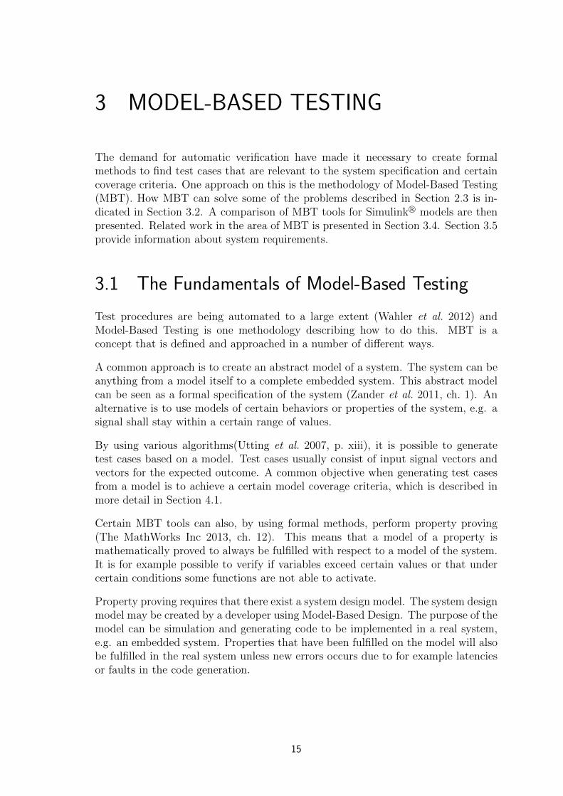
3 MODEL-BASED TESTING
The demand for automatic verification have made it necessary to create formalmethods to find test cases that are relevant to the system specification and certaincoverage criteria. One approach on this is the methodology of Model-Based Testing(MBT). How MBT can solve some of the problems described in Section 2.3 is in-dicated in Section 3.2. A comparison of MBT tools for Simulinkr models are thenpresented. Related work in the area of MBT is presented in Section 3.4. Section 3.5provide information about system requirements.
3.1 The Fundamentals of Model-Based Testing
Test procedures are being automated to a large extent (Wahler et al. 2012) andModel-Based Testing is one methodology describing how to do this. MBT is aconcept that is defined and approached in a number of different ways.
A common approach is to create an abstract model of a system. The system can beanything from a model itself to a complete embedded system. This abstract modelcan be seen as a formal specification of the system (Zander et al. 2011, ch. 1). Analternative is to use models of certain behaviors or properties of the system, e.g. asignal shall stay within a certain range of values.
By using various algorithms(Utting et al. 2007, p. xiii), it is possible to generatetest cases based on a model. Test cases usually consist of input signal vectors andvectors for the expected outcome. A common objective when generating test casesfrom a model is to achieve a certain model coverage criteria, which is described inmore detail in Section 4.1.
Certain MBT tools can also, by using formal methods, perform property proving(The MathWorks Inc 2013, ch. 12). This means that a model of a property ismathematically proved to always be fulfilled with respect to a model of the system.It is for example possible to verify if variables exceed certain values or that undercertain conditions some functions are not able to activate.
Property proving requires that there exist a system design model. The system designmodel may be created by a developer using Model-Based Design. The purpose of themodel can be simulation and generating code to be implemented in a real system,e.g. an embedded system. Properties that have been fulfilled on the model will alsobe fulfilled in the real system unless new errors occurs due to for example latenciesor faults in the code generation.
15

16 Chapter 3 Model-Based Testing
The most important differences between property proving and test cases are wherethey are applicable and how extensive they are. Property proving is a much morethorough verification method since it actually proves that a property is fulfilled atall times. Property proving is however limited to Model-In-the-Loop (MiL) testingwhile test cases can be used anywhere from MiL to Hardware-In-the-Loop (HiL)environments by the use of an adaptor model for creating executable test scripts(Utting et al. 2007, ch. 2.2).
3.2 Possibilities for improvements
MBT can help finding requirement errors in an early phase, since a formal and precisemodel has to be created based on the system requirements (Utting et al. 2007,ch. 2.7). When creating a model of a requirement it is reviewed from a differentperspective, which can help find ambiguities. Model-based tests can also find morerequirement errors than manually created tests, when executing the test cases in alater phase (Pretschner et al. 2005). This indicates that MBT could be part of thesolution for finding ambiguous, contradictory or incomplete requirements.
A model of the system behavior can be created based on a test scope, thereforebecoming more abstract than the System Under Test (SUT) (Utting et al. 2007,ch. 3.1),(Broy et al. 2005, ch. 10). The model could then act as a specification atthe Electronic Control unit (ECU) level which could solve the problem concern-ing specifications at this level. The behavior model can also be created at higherabstraction levels such as combining ECUs to subnets or considering the completevehicle as the SUT. An adaptor for the generated test can then be used to concretizethe test cases for execution on the test system (Utting et al. 2007, ch. 2.2),(Broy etal. 2005, ch. 15).
Different case studies have shown that MBT can lead to savings by reducing devel-opment costs by 20-30% (Zander et al. 2011, ch. 1.4). MBT also has possibilities fortime saving when the requirements change. Instead of updating all tests manually,the test model, which is much smaller, is updated and the new tests are automati-cally generated (Zander et al. 2011, ch. 6.1). By using a system design model as theSUT and applying MBT the verification can start early in the development, beforeany hardware exists.
3.3 Tools for Model-Based Testing
The tool used in this study is Simulinkr Design Verifier� (SLDV), which is a toolboxfor Simulinkr and is presented in detail in Chapter 4. There do however existalternative software for applying MBT on Simulinkr models. Some will be presentedin this section. A more in-depth analysis of different tools have been done by Zander-Nowicka (2009, ch. 3).

3.4 Related work 17
Reactis from Reactive Systems1 allows for automatic test case generation and prop-erty proving. Test cases can be generated from state machines that are modeled inthe tool. For property proving it is possible to model properties using Simulinkr oras c-code like syntax of Reactis.
TPT (Time Partition Testing) from PikeTec GmbH2 have support for test casegeneration. Test cases are specified as automata. TPT can automatically generatea test harness in Simulinkr and simulate the test cases on a system design model.
T-VEC from T-VEC Technologies3 analyze Simulinkr models and identify modelingfaults such as dead logic. Test cases that achieve a certain coverage objective canbe generated from the system design model.
SLDV is capable of both automatic generation of test cases and proving properties.The advantage of using SLDV is that both property and system modeling can occurin the same environment. Properties and models used for test case generation canbe created in a wide verity of ways. It can be done in either Simulinkr, Stateflowr
or as MATLABr code.
3.4 Related work
How to work with MBT and the process from requirement all the way to test exe-cution is covered by several books and papers (Utting et al. 2007, ch. 2), (Broy etal. 2005, ch. 10). These cover a general approach to software testing using MBT butthere also exist material with more focus on Simulinkr and the automotive industry(Bringmann and Kramer 2008), (Zander et al. 2011, ch. 19).
The generation of test cases is also a well researched area. Test cases from Simulinkr
and Stateflowr models can be generated by translating the model to an extendedfinite automaton and analyzing its paths (Li and Kumar 2012). Another way togenerate test cases which have been proven useful, is the use of a model checkingtool (Micskei and Majzik 2006), (Mohalik et al. 2014).
The common factor for these studies are that the actual system is not the mainfocus. This thesis aims to contribute by making further connections to the actualSUT and instead focus on different types of specifications and behavior. By doingthis the usefulness of MBT in an industrial context can be further evaluated.
Using a model checker for Stateflowr models, a model can be verified by definingsystem properties in a model checker (Chen et al. 2012). This method can alsofind design errors and provide counterexamples for debugging. Similar to (Chen etal. 2012), the work in this thesis also cover verification of properties (with propertyproving) but instead has an approach that reduces the number of tools needed.
1http://www.reactive-systems.com/products.msp2http://www.piketec.com/products/tpt/matlab-simulink.php3http://www.t-vec.com/solutions/simulink.php

18 Chapter 3 Model-Based Testing
This is achieved by using Simulinkr and Stateflowr for both system and propertymodeling together with SLDV for verification of the properties.
A case study used SLDV on a train tracking function for an automated train pro-tection system (Etienne et al. 2010). Different proof strategies were presented suchas proof by induction. A property is proven to hold in the first time step and whenproving that it holds in the next time step it is assumed that it holds for all theprevious time steps. The case study showed that property proving on a varietyof behavior is possible, including safety properties. This is closely related to thepresented case in terms of procedure and tool selection. The train tracking func-tion have a somewhat different specification which is more mathematically complexcompared to the presented case, which has a more event based specification.
To summarize, the processes and techniques behind Model-Based Testing are rel-atively widely researched. Different tools have been created and studied, but thepractical use of Simulinkr models together with MBT in Simulinkr Design Verifier�has not gained much attention. The topic of this thesis is chosen for this reason.
3.5 Requirement specifications
Requirements can exist in two domains; the problem and the solution domain (Hullet al. 2011, ch. 1.9). The first of these focuses on the stakeholder’s (owner’s, cus-tomer’s, etc.) view, therefore the requirements in this domain explains what prob-lems the stakeholders want to solve. The requirements of the solution domain insteadputs focus on what the system will do, hence they are often referred to as systemrequirements (Hull et al. 2011, ch. 1.9). All requirements for lower level parts, e.g.subsystems and components, belong to this domain.
It is common to separate the system requirements into functional and non-functionalrequirements (Glinz 2007). Since the definition of a non-functional requirement isunclear (Chung and Prado Leite 2009),(Glinz 2007), a different separation will beused. This separation, created by Glinz, is based on a more detailed taxonomy thatsplits up the non-functional requirements into more clearly defined types based onconcerns (Glinz 2007). These types are shown in Figure 3.1.
Figure 3.1. Separation of system requirements into different types based onconcerns.

3.6 Summary 19
A functional requirement concerns the behavior of the system and the expectedoutput for some input. Performance requirements concerns timing, speed, volumeand throughput. A specific quality requirement concerns the qualities described inISO/IEC 9126-1 (ISO/IEC 2001), which describes for example system security andusability. Constraints limits the possible solutions further than what is required tomeet the functional, performance and quality requirements. This can be for examplephysical, legal or interface constraints.
Since the standard ISO/IEC 9126-1 has been superseded by ISO/IEC 25010, Glinz’s(2007) taxonomy will be used with the exception of quality requirements insteadconcerning the qualities described in ISO/IEC 25010 (ISO/IEC 2011).
3.6 Summary
This chapter presented different tools and related work to give a broader pictureon the subject of MBT. To form a foundation for answering the research questionabout requirement types, Section 3.5 explains different aspects of this topic. Sec-tion 3.1 explained the fundamentals of MBT which provides necessary backgroundinformation for Chapter 4.

20 Chapter 3 Model-Based Testing

4 SIMULINK DESIGN VERIFIER
This chapter will cover Simulinkr Design Verifier� (SLDV), which is a toolboxfor Simulinkr that is meant for finding design errors and formal verification. Thefirst version of SLDV was released in 2007 by The MathWorks. Simulinkr DesignVerifier� is capable of both property proving and automatic test case generation(explained in Section 3.1). To perform property proving and test case generationSLDV uses Prover Plug-In1 from Prover Technology (The MathWorks Inc 2013,ch. 1). Another feature in SLDV is design error detection which can identify designerrors such as dead logic and division by zero. This feature will however not befurther mentioned since this thesis focus on formal verification against requirements.
Section 4.1 will explain some of the features of SLDV that are necessary as back-ground information for coming sections. Three methods of modeling requirementsthat utilizes different features in SLDV are introduced in Section 4.2. These are:the proof objective model, test objective model and cause-effect graph.
Not all Simulinkr models are compatible with SLDV. One of the limitations isthat a fixed step solver must be used. Certain blocks are not supported, e.g. theblocks in the continuous library. Some blocks that are not supported can howeverbe replaced using automatic block replacement (The MathWorks Inc 2013, ch. 3).A consequence of block not being supported is that a lot of work might be necessaryto redesign the model to get it compatible, e.g. in control systems the controllerhave to be replaced with a discrete controller.
4.1 Features and Fundamentals
SLDV comes with special blocks such as the proof objective block and the testobjective block to instruct that a property shall be proved or a test case shall begenerated. It is also possible to generate test cases by specifying a model coverageobjective that shall be obtained by the test cases. Coverage criteria describes howwell a test suite covers different parts of a model. In SLDV the following control-flowbased coverage criteria (The MathWworks Inc 2013, ch. 15), (Zander et al. 2011,p. 87) (Utting et al. 2007, ch. 4.1.1) is used:
Decision coverage - The percentage of the possible decision paths through a model.For a test suite of a state chart to achieve full decision coverage all entry and exitpaths through a state must be evaluated by test cases. In Simulinkr decision pathscan be for example Switch-blocks. The model in Figure 4.1 has two decision paths.To achieve full decision coverage both these paths need to be taken by test cases.
1http://www.prover.com/products/prover_plugin/
21

22 Chapter 4 Simulink Design Verifier
Condition coverage - The percentage of the total number of logical inputs andtransitions that are covered. All guards in a state chart must be evaluated to bothtrue and false by different test cases to achieve full condition coverage. In Simulinkr
the parts affected by condition coverage are for example Stateflowr transitions andblocks with logical functions. In the model in Figure 4.1 there are two guards, In1and In2. To achieve full condition coverage both In1 and In2 have to be as trueand false.
Modified Condition/Decision Coverage (MCDC) - Extends decision and con-dition coverage by showing the independence of logical input and transitions. Fora test suite to achieve full MCDC every input to a logical function or a transitionmust be changed independently while the other inputs remain fixed. To achieve fullMCDC In1 and In2 have to be as evaluated as true and false independently.
There are three alternatives when choosing coverage criteria objective: decision,decision and condition or MCDC. Decision coverage gives the least extensive testcases while MCDC gives the most extensive. Using decision coverage objective onthe state chart in Figure 4.1 gives the test case in Table 4.1. If MCDC objective isused then the test case in Table 4.2 is given.
[In1 || In2]1
{Out1 = false;}2
{Out1 = true;}
Figure 4.1. An small Stateflowr model used to explain coverage criteria. Deci-sion path 1 is taken when In1 or In2 is true and path 2 is taken when both In1
and In2 are false.
Table 4.1. Generated test case from the model in Figure 4.1 using full decisioncoverage objective.
Step 1 2
Generated Input Data In1 0 0In2 1 0
Expected Output Out1 1 0
Generated test cases can be simulated in a test harness, as seen in Figure 4.2.After test cases have been generated this harness can be automatically generated.Simulating the test cases will provide a report containing how much of the systemwas covered.
4.1 Features and Fundamentals 23
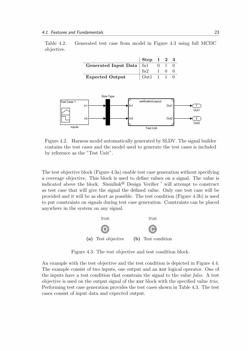
Table 4.2. Generated test case from model in Figure 4.3 using full MCDCobjective.
Step 1 2 3
Generated Input Data In1 0 1 0In2 1 0 0
Expected Output Out1 1 1 0
verificationLayout
In1
In2
Out1
Out2
Test Unit
In1
In2
Test Case 1
Inputs
In1
In2
Out1
Out2
Size-Type
1
Out1
2
Out2
Figure 4.2. Harness model automatically generated by SLDV. The signal buildercontains the test cases and the model used to generate the test cases is includedby reference as the ”Test Unit”.
The test objective block (Figure 4.3a) enable test case generation without specifyinga coverage objective. This block is used to define values on a signal. The value isindicated above the block. Simulinkr Design Verifier� will attempt to constructas test case that will give the signal the defined value. Only one test case will beprovided and it will be as short as possible. The test condition (Figure 4.3b) is usedto put constraints on signals during test case generation. Constraints can be placedanywhere in the system on any signal.
true
(a) Test objective
true
(b) Test condition
Figure 4.3. The test objective and test condition block.
An example with the test objective and the test condition is depicted in Figure 4.4.The example consist of two inputs, one output and an xor logical operator. One ofthe inputs have a test condition that constrain the signal to the value false. A testobjective is used on the output signal of the xor block with the specified value true.Performing test case generation provides the test cases shown in Table 4.3. The testcases consist of input data and expected output.

24 Chapter 4 Simulink Design Verifier
XOR
Logical Operator
truefalse
1
In1
2
In2
1
Out1
Figure 4.4. A small example with the test objective and the test condition. Theobjective is to generate a test case where the output from the xor block is truewith one of the inputs constrained to false.
Table 4.3. Generated test case from model in Figure 4.4.
Step 1
Generated Input Data In1 0In2 1
Expected Output Out1 1
The proof objective block (Figure 4.5a) is used to prove that a signal always have thevalues that are specified. No simulations are made to perform this task, instead amathematical proof is constructed to verify that the objective is fulfilled at all times.If the objective can not be proven valid a counterexample is generated, containinga test case as short as possible that moves the system to a state where the objectiveis not fulfilled. The assumption block (Figure 4.5b) is used to constrain signals justas the test condition block. The difference is that the assumption block is ignoredwhen performing test case generation and the test condition block is ignored whenperforming property proving.
true
(a) Proof objective
true
(b) Assumption
Figure 4.5. The proof objective and assumption block.
In Figure 4.6 a model with a proof objective and assumption is shown. The assump-tion block constrains one of the inputs to true. In this example Simulinkr DesignVerifier� will attempt to prove that the output from the xor block always is true.Performing property proving will prove the objective unsatisfiable and provide acounterexample. The counterexample can be seen in Table 4.4. The counterexam-ple is an input vector where both input signals are true. This makes the output ofthe xor block false which is a violation of the proof objective.

4.2 Modeling requirements 25
XOR
Logical Operator
true
1
In1
2
In2
1
Out1
true
Figure 4.6. A small example with the proof objective and the proof assumption.The objective is to prove that the output from the xor block always is true whenone of the inputs are constrained to be false.
Table 4.4. Counterexample from model in Figure 4.6.
Step 1
Counterexample In1 1In2 1
Expected Output Out1 0
4.2 Modeling requirements
This section will present three methods of modeling requirements in Simulinkr
for use with formal verification such as property proving and automatic test casegeneration. The three methods use different features of Simulinkr Design Verifier�.The proof objective model is meant for property proving. The test objective modelis meant for test case generation using a test objective block and the cause-effectgraphs are also meant for test case generation but uses a coverage objective to doso.
The layout used for performing some of the Model-Based Testing (MBT) featuresoften contain a system design model and a verification subsystem, as shown inFigure 4.7. Inside the verification subsystem proof and test objectives are modeledin terms of the Input/Output (I/O) signals of the system model. Cause-effect graphsare separate models where the generated test cases are independent of the systemdesign model.
4.2.1 Proof objective models
The proof objective model is a formal representation of a requirement that is usedto perform property proving on a system model. A requirement is modeled insidea verification subsystem (Figure 4.7) using the inputs and outputs of the system.The requirement can be modeled in Simulinkr directly or as Stateflowr charts orMatlab-functions. (The MathWorks Inc 2013, ch. 12)

26 Chapter 4 Simulink Design Verifier
1
In1
1
Out1
2
Out2
2
In2
System model
Out1
Out2
In1
In2
Verification Subsystem
Figure 4.7. Common model layout for Model-Based Testing tasks usingSimulinkr Design Verifier�.
A generic model of a requirement can be seen Figure 4.8. The condition and theexpected result are modeled using the signals of the system and logic operators.With the generic proof objective model the task for Simulinkr Design Verifier� isto prove that
Condition ⇒ Expected result (4.1)
always is true.
1
Condition signals
2
Outcome signals
Condition
Expected result
A
BA ==> B
true
Figure 4.8. Generic proof objective model.
If the condition cannot be fulfilled by the system model then the proof objective willnever be violated. To make sure that the condition can be fulfilled a test objectiveblock can be placed after the condition with the specified value true. If a test casecan be generated then the condition can be fulfilled.
4.2.2 Test objective models
The concept behind this method is to use the system model and the test objectiveblock. The layout when working with test objective models are similar to the onefor proof objective models. The signals from the system model are used to createthe conditions and expected results. In Figure 4.9 an example of a test objectivemodel is depicted.

4.2 Modeling requirements 27
1
Condition signals
2
Outcome signals
Condition
Expected result
AND
true
Figure 4.9. Example of a test objective model. The test objective model isplaced beside the system model and is connected with its signals.
A test case will be generated that fulfills the condition and expected result. Atest case generated from the system design model and a test objective model willcontain input signals and expected output for all inputs and outputs of the system.Since other signals are involved in the test case it can not be said for sure thatthe condition caused the expected result to occur. One way of handling this is toconstrain input signals that shall not be involved in the test case.
Unlike the proof objective model that proves that a property cannot be violated,the test objective model will only test if the property can be fulfilled.
4.2.3 Cause-effect graphs
Cause-effect graphs (Figure 4.10) is a common approach in software testing. Theconcept is to use graphs to connect different causes to different effects. The cause-effect graphs are based directly on a requirement and provides a formal way ofverification. It is suitable for requirements that state the relationship between inputand output signals. In this thesis the basis for applying cause-effect graphs arethe approach presented by Lee and Friedman (2013). With SLDV it is possible togenerate test cases based on the cause-effect graphs by selecting a coverage objective,e.g. decision, decision/condition or MCDC (see Section 4.1).
Reference model Test oracle
Input1
Input2
Condition1
Condition2
Condition3
Condition1
Condition2
Condition3
Output1
Output2
true
1
Input1
2
Inpu2
1
Output1_oracle
2
Output2_oracle
true
true
Figure 4.10. A cause-effect graph. The input signals causes conditions to befulfilled. The oracle determine the expected output based on active conditions(effects).

28 Chapter 4 Simulink Design Verifier
The model contains two directed tree graphs; the test reference and the test ora-cle. Both of these are modeled in Stateflowr. The reference model(Figure 4.11a)determine if a condition (effect) is fulfilled based on input signals (causes). Theoracle (Figure 4.11b) decides the system output, based on fulfilled conditions. Therequirement in Figure 4.11 states that:
� If Input1 and Input2 are true then
Output1 and Output2 shall be true.
� Else if Input2 is true then
Output1 shall be true and Output2 shall be false.
� Else
Output1 shall be false and Output2 shall be true.
[Input2]
1
2
{Condition1 = true;}
{...Condition1 = false; ...Condition2 = false; ...Condition3 = false,}
{Condition2 = true;}
[Input1 && Input2]
1
{Condition3 = true;}2
(a) Chart in Reference model
2 {Output1 = true;}
{...Output1 = false; ...Output2 = false; ...}
2
[Condition2]1
[Condition1]1
{Output1 = true; ...Output2 = true;}
{Output2 = true;}
[Condition3]
(b) Chart in Test oracle
Figure 4.11. Details of the different parts in a cause-effect graph.
There are three different outcomes specified in this requirement. This determineshow many effects (conditions) there are. The different decision paths in the referencemodel are directly related to the three statements in the written requirements.
A benefit of separating the requirement between the reference model and test oracleis to give more control over the test case generation. With the separation it is forexample possible to only generate test cases for when only one condition is activeor when one condition is always false. All of this is done by using test conditionblocks on the signals between the reference model and test oracle. To generate testcases where any of the conditions is fulfilled an or block and test condition blockwith the signals can be used.

4.3 Summary 29
Unlike the test objective models, only the signals that are specified in the require-ment are included in the generated test cases. This assures that it is the desiredinputs that causes the expected outcome. With the test objective model only onetest case are generated per model. With a cause-effect graphs it is possible to gen-erate either a long test case or several test cases that cover the whole requirement.
To do Model-In-the-Loop (MiL) verification a test harness is created. A harnesscan be created with a command after test case generation has been performed. Thetest harness contain the cause-effect graph along with the test cases that are placedinside a signal builder. A copy of the system design model is also included andsimulated side by side with the cause effect graph that functions as a test oracle.The setup is depicted in Figure 4.12. If the output from the system model differ fromthe oracle then the test case is not fulfilled and thus the corresponding requirementis not fulfilled.
Signald1
Signald2
Testdcased1
Testdcases
In1
In2
Out1
Out2
Size-Type
Signald1
Signald2
Oracle_out
Oracle(Cause-Effectdgraph)
System_model
Signald1
Signald2
System_out
Model
1
Oracle_out
2
System_out
Figure 4.12. Test harness for executing test cases on system model and testoracle.
4.3 Summary
The purpose of this chapter was to present the SLDV toolbox and introduce thethree different modeling methods. These methods will be used in Chapter 7 wherethe research question about how requirements are modeled to be used for MBT isanswered.

30 Chapter 4 Simulink Design Verifier

5 THE CASE STUDY
To answer the research questions a case study that contained both modeling andtesting of a vehicle was conducted. The basis for the case was an existing Simulinkr
model that implemented some of the functionality for the exterior lights system ofa truck. Focus was put on Automatic Headlight Switching (AHS), a system thatautomatically activates the headlights during nighttime.
5.1 Case selection
The case was selected since it allowed an investigation of the problems described inSection 2.3. These concerned incorrect requirements, test case creation, non-existingrequirements on the Electronic Control unit (ECU) level and the need for earliertesting.
Another factor in choosing the case was the system’s complexity regarding func-tionality. It was complex enough to contain different types of behavior and a highamount of requirements, but not so complex that low-level details had to be disre-garded. The available information and its efficient structure was also crucial whenselecting the case. This information consisted of requirements on both low and highlevel together with test cases on system level. All this allowed to easier understandthe system structure and its behavior.
The functionality for AHS was under development at the time when the case studywas conducted. Due to this there existed possibilities to find more errors, whichmight not have been the case for a highly matured functionality. This correspondedwell with the research question concerning error detection.
The previously made Simulinkr model allowed to focus on modeling the systemfunctionality and requirements instead of its framework and interfaces. Since themodel also contained some functionality, the requirement modeling for the differ-ent methods and the exploration of Simulinkr Design Verifier� (SLDV) could beinitiated early in the study.
5.2 The system for Automatic Headlight Switching
The functionality for AHS is a distributed system where several ECUs and compo-nents are included. Multiple light sources also have a connection to AHS. The mostimportant parts are visualized in Figure 5.11.
1Sources, component images: Volvo Trucks Image Gallery and Volvo Group Truck Technology
31

32 Chapter 5 The case study
Figure 5.1. Connection between the main parts of the AHS. The ECUs alsohave connections to other parts contributing to different functionality than theAHS, but these are not shown here.
The twilight sensor measures the ambient light and uses this to request activationof dipped beam or Daytime Running Lights (DRL). The Light Control Panel (LCP)is a freewheel switch used to select light mode, where different modes activates anddeactivates certain functionality of the exterior lights. The main beam stalk is usedto toggle between main and dipped beam. It can also be used to activate the mainbeam temporarily, called Flash-to-pass. The ECUs connected to these componentscontains basic functionality and forwards commands to the Vehicle Master ControlUnit (VMCU). The VMCU makes decisions about which light sources to activatebased on the twilight sensor, LCP and main beam stalk. The light sources whichhave a connection to AHS are briefly described in Table 5.1.
Table 5.1. Light sources affected by the AHS
Component Description
Position lightsCreates basic conspicuousness for the vehicle. Alsoindicates width and height.
Daytime Running LightsIncreases the conspicuousness for the vehicle dur-ing daytime driving.
Dipped beam headlightsUsed when meeting oncoming traffic during night-time driving.
Main beam headlightsCreates better visibility for the driver at nighttimedriving.

5.3 Specification of the system 33
5.3 Specification of the system
The system is specified using End-to-End (E2E) functions, describing the func-tionality from the users point of view, and several Logical Design Components(LDCs), which represents different software components. The LDC specifies whichInput/Output (I/O) signals that are present, both in terms of signal names andencoded values, and the behavior based on these signals. Combinations of LDCsrealizes an E2E function and the combination of End-to-End Functions (E2EFs)and LDCs realizes a Collaboration, which represents the complete functionality.
The AHS function is mainly distributed over four LDCs, one for the Twilight sensorand the LCP respectively as well as two LDCs which are both part of the VMCU:
� ExteriorLightsCtrl - Sends commands to control the different light sources andcorresponding dashboard indicators. These commands are based on requestsfrom TwilightSensor and ExteriorLightsHMICtrl and the Main Beam Stalk.
� ExteriorLightsHMICtrl - Uses information from the LCP together with statusfrom ExteriorLightsCtrl to request changes in light mode and activate indica-tors corresponding to the currently selected mode.
The connections between these LDCs, the relevant E2EFs and Collaboration arevisualized in Figure 5.2.
Figure 5.2. Connections between Collaboration (top level), E2E functions (mid-dle level) and LDCs (bottom level)
A key part in specifying the LDC behaviors is the use of vehicle modes to representthe different overall states, that are described in Table 5.2. Another important partof the specification is the light mode (controlled by the LCP) which is described inTable 5.3.

34 Chapter 5 The case study
Table 5.2. The different vehicle modes available. These are closely related tothe position of the ignition key.
Vehicle mode Description
Hibernate The vehicle is in production or being delivered to end customer.
LivingThe vehicle is parked and the driver is inside. Only some func-tionality is available, to reduce electrical energy consumption.
Accessory Same as for Living but more functionality available.
PrerunningThe driver is about to start the engine. Functionality needed forthe powertrain is available.
CrankingThe engine is starting. This mode is only active for a short timewhen moving between Prerunning and Running.
RunningThe engine is running and the vehicle is in motion or performingstandstill operations.
Table 5.3. The different light modes that can be active.
Light mode Description
Park Activates the parking lights.
OFF/DRL Deactivates main and dipped beam headlights. Activates AHS.
Drive Activates the dipped beam and allows activation of main beam.
Drive+Activates the dipped beam and allows activation of main beamtogether with extra main beam.
5.4 Existing Simulink model
To perform the Model-Based Testing tasks a previously made Simulinkr modelwas used. This model mapped all LDCs (which are part of the Collaboration) tocorresponding subsystems and connected them with the specified signals. The partof the model relevant for AHS is shown in Figure 5.3.
The subsystems included the main behavior for Vehicle modes Running or Prerun-ning, but these modes were assumed and a way of alternating between modes wasnot modeled.

5.5 Limitations 35
FogLightRearCtrlStatus
FogLightFrontCtrlStatus
HeadLightToggleCtrlStatus
LCP_Status
MainBeam_StalkStatus_7
MainBeam_StalkStatus_8
LightMode_Status_Ctr_7
LightMode_Status_Ctr_8
DRL_ButtonStatus
ExtraMainbeam_SwitchStatus
AutoHeadlightSwitching_rqst
ParkingLight_Indication
DrivingLight_Indication
DaytimeRunningLight_Indication
DrivingLightPlus_Indication
DirectionIndicatorLights_rqst
HeadLightsMainBeamToggleRqst
LightSwitch_rqst
ExtraMainbeam_Mode
ExtLightFreewheel_Ind
ExteriorLights_HMICtrl
LightMode_Status_7
LightMode_Status_8
LightMode_Status_Ctr_7
LightMode_Status_Ctr_8
ExteriorLightPanels_Freewheel_Gw
HeadLightsMainBeamToggleRqst
LightSwitch_rqst
ExtraMainbeam_Mode
AutoHeadlightSwitching_rqst
AmbientLight_stat
ExtraLDRLInhibition_rqst
ExtraLMainbeamInhibit_rqst
FogLightRearCtrlStatus
FogLightFrontCtrlStatus
HeadLightToggleCtrlStatus
LCP_Status
DippedBeam_cmd
MainBeam_cmd
PositionLight_cmd
DRL_cmd
MainBeam_InRoofSign_cmd
ExtraMainBeam_cmd
DippedBeamIndication_cmd
MainBeamIndication_cmd
PosLight_Indication_Cmd
PosLightWarning_rqst
DRLRequest_status
ExteriorLights_Ctrl
AmbientLight_Lux
LIN_AutoHeadlightSwitch_rqst
LIN_AmbientLight_stat
TwilightSensor_Mgr
8
AmbientLight_Lux
3
LightMode_Status_7
7
MainBeam_StalkStatus_7
4
ExtraLDRLInhibition_rqst
5
ExtraLMainbeamInhibit_rqst
7
LCP_Status
8
DippedBeam_cmd
6
DippedBeamIndication_cmd7
MainBeamIndication_cmd
4
PositionLight_cmd5
DRL_cmd
3
MainBeam_cmd
8
DRLRequest_status
Figure 5.3. Part of the previously made Simulinkr model, where the subsystemsfor AHS are shown.
5.5 Limitations
There exists limitations both regarding system behavior and specification. Since nodynamical behavior, such as filtering or automatic control, is part of the system noresults can be obtained regarding Model-Based Testing of this area. An automotivefunctionality that would cover this could be for example cruise control or filteringof radar measurements for an active safety system.
There is also no data processing, in terms of mathematical calculations, in thesystem. This further limits the applicability of the results. All behaviors are possibleto model with the standard Simulinkr blocks supported by SLDV. For this reasonto data could be obtained about requirement modeling and applying SLDV featuresto user defined functions.
Even though the specification covers higher level behavior, the number of require-ments on this level limited the amount of data that could be obtained, thus makingthe results less reliable. There are also no specifications considering decision mak-ing at an abstract level which limits the results regarding the different method’sapplicability for system level testing.

36 Chapter 5 The case study
5.6 Summary
This chapter has provided a motivation for selecting the case as well as the case’slimitations. This information is necessary when putting the answers to the researchquestions in a wider context and discussing how well the case represents other em-bedded systems.
The explanation of the system structure, its components and its specification pro-vides a foundation for understanding the answers to the research questions makesit easier to connect the details of these answers.
Chapter 6, 7 and 8 will now cover the research questions presented in Section 1.2,which regards: the types of requirements for an embedded system, how they aremodeled and what Model-Based Testing (MBT) method that is appropriate foreach type.

6 REQUIREMENT TYPES OF AN AUTO-MOTIVE EMBEDDED SYSTEM
This chapter covers the research question:
� What types of software requirements exists for an automotive embedded sys-tem and which are most common?
The requirements for the Collaboration, End-to-End Functions (E2EFs) and LogicalDesign Components (LDCs) described in Chapter 5 have been manually read andanalyzed. They have then been grouped according to the theory described in Section3.5. For the most common type different subtypes are identified, based on definitionsprovided in this thesis.
The answer to the question about what types of requirements exist is presentedin Section 6.1 and in the following sections the types are described and the mostcommon types are mentioned. The answer is summarized in Section 6.5.
For confidentiality reasons, the complete data for the analysis can not be presentedin this thesis. However, the examples for the requirement types are real data, toprovide a hint of how the requirements of the system are formulated.
6.1 Identified requirement types
The requirements for each the three system levels are specified at different abstrac-tion levels. LDC requirements are detailed and relates to the system implementation.At this level explicit signal names and encoded values are used. Behavior for differ-ent truck variants are also specified. The requirements on End-to-End (E2E) levelare written on a higher level in such way that they do not use explicit signal namesand do not relate to a specific truck configuration. Requirements on Collaborationlevel are based on use cases and scenarios, explaining some expected outcome forcertain system level conditions.
Of the main requirement types, based on Glinz’s (2007) taxonomy explained inSection 3.5, all types exists in the specifications for the Exterior lights system. Forthe first three main requirement types only one subtype is present for each one. Forthe functional type the requirements are formulated in a number of different ways,therefore this main type is split into new subtypes which are defined in this thesis.Figure 6.1 shows the identified and created requirement types connected to the maintypes.
37

38 Chapter 6 Requirement types of an automotive embedded system
Figure 6.1. Connection between the main requirement types and the identifiedsubtypes. Types defined by others have dashed outline and the types definedin this thesis (which are based on requirements from the case study) have solidoutline.
The separation of functional requirements relates closely to modeling similarities interms of block types. Both the textual requirement statements and the block typeshas differences in how time takes part which makes this a useful separation whenanswering questions about modeling in later chapters.
6.2 Description of requirement types
The identified subtypes of the four main requirement types are described in detailbelow. For each type of functional requirement the created definition of the identifiedtype is also presented.
ConstraintsOnly one constraint was present in the specification, this was a legal constraint pro-hibiting certain combinations of light sources being active. Due to the low quantity,this type will not be further analyzed. The outcome of the constraint will still bepresent through a undesired behavior-requirement (stated as an example below).
Example:The vehicle shall conform to ”United Nations Regulation ECE48-3 - Lighting andlight signalling devices”.
Performance requirementsThis main type only consisted of latency requirements stating a required maximumresponse time from input condition to output action.
Example:The delay from driver requesting activation of Daytime Running Lights (DRL) toswitching on the DRL lights shall be maximum 250ms.

6.2 Description of requirement types 39
Specific quality requirementsOf this main type only adaptability requirements existed, based on the definitionsof ISO/IEC 25010 (ISO/IEC 2011). These requirements are stating that it shall bepossible to control a certain behavior with a configuration parameter.
Example:It shall be configurable whether the DRL is enabled or disabled.
OperationalSpecifies that it shall be possible to activate a signal or function at some conditions,often in which Vehicle mode(s) and without specifying a complete condition basedon all input signals that can affect the behavior.
Definition: A requirement stating output signal values for a condition which is notnarrow enough to consider the requirement fully tested if the condition is fulfilled.
Example:Daytime Running Lights shall be operational in VehicleMode Running.
StaticFor the collaboration level this type specifies an expected output for some specificconditions and a change in system input. At E2E level this requirement type ex-plains when a functionality shall become activated, but at a higher abstraction levelwithout details about specific signals or values. At LDC level these requirementsare often formulated as a nested if-statement, where a certain combination of inputsignals and vehicle modes shall lead to a certain combination of output signals.
Definition: A requirement stating output signal values for a condition purely basedon the current input signal(s).
Example:If MainbeamCmd or DippedBeamCmd is ON,HeadLampStat shall be set to ON
TemporalSpecifies a condition for when an output shall become activated, based on bothsignal values and time. This type mostly consists of failure handling requirementsstated as the example.
Definition: A requirement stating output signal values for a condition being fulfilled:for, after or before some time interval or value.
Example:If Input signal is received with the value Error, then the previous value shall beassumed during the first Delay seconds. If no previous value exists, the value Defaultshall be used. If the signal still has value Error after this timeout, the value Defaultshall be used.

40 Chapter 6 Requirement types of an automotive embedded system
TransitionSpecifies a behavior when input signals change or changes between specific values.
Definition: A requirement stating output signal values for a condition based on thetime instant when a signal changes value.
Example:When VehicleMode transitions from Running to Cranking the Main beam shall bedeactivated.
SequentialThis type is used to specify sequences for a Human-Machine Interface (HMI) con-sisting of various buttons and stalks. Requirements if this type are formulated asstate machines, where different values for an output signal is set for different states.Conditions on signals specifies the transitions.
Definition: A requirement stating output signal values for a condition specifying acertain sequence of input signal values.
Example: Figure 6.2 shows an example of a sequential requirement. This representtoggling between main and dipped beam by pushing the main beam stalk and thenreleasing it back no its neutral position.
Figure 6.2. Example of a sequential requirement. In addition to the statemachine output signals for each state is specified.
Undesired behaviorThis type contains requirements stating that something shall not happen. This canbe both a purely undesired behavior, e.g. stating a safety property or a prohib-ited behavior as a cause from a legal requirement, but also a part of some wantedbehavior, e.g that a signal shall not change at certain conditions.
Definition: A requirement stating that output signals that shall not attain somevalue(s) for a certain condition that is not narrow enough to consider the requirementfully tested if the condition is fulfilled.
Example:Dipped beam or main beam shall not be activated when the position lights are notactivated.

6.3 Common requirements 41
6.3 Common requirements
The manual analysis resulted in a total of 420 requirement statements being groupedinto the explained types. The simpler requirements which could be combined withone or-statement were counted as one requirement statement. The more complexrequirements, e.g. nested if-statements of the static type, were counted as severalstatements based on the number output signal combinations and grouping in thetextual specification. The number of requirement statements for each requirementlevel and type are presented in Figure 6.3.
Operational Static Temporal Transition SequentialUndesired
behaviorLatency Adaptability
Legal
constraint
LDC 0 241 39 11 8 7 1 23 0
E2E 10 15 1 5 0 20 11 7 1
Collaboration 0 12 9 0 0 0 0 0 0
0
50
100
150
200
250
300
Nu
mb
er
of
req
uir
em
en
ts
Requirement types
Figure 6.3. Number of requirements for each requirement type for the threespecification levels.
The most common requirement types for the Automatic Headlight Switching (AHS)are the static functional requirements which represents 64 % of the total amountwhen combining requirements at all levels. This is also the most common require-ment type at LDC level.
At E2E level the number of requirements are more evenly distributed over the dif-ferent types than the other levels. Most of the undesired behavior is specified here,due to the signals in this type often being scattered over multiple LDCs. The re-quirement: The main beam headlights shall not be deactivated as long as the drivermakes a request for temporary activation (flash-to-pass) with the main beam stalk,contains signals present in ExteriorLightsCtrl (main beam headlights) and Exteri-orLightsHMICtrl (main beam stalk).

42 Chapter 6 Requirement types of an automotive embedded system
6.4 Discussion
If a requirement belongs to a certain type can be a matter depending on the sur-rounding requirements. For example, ”Signal X shall not be false when signal Y istrue” could be considered both a static and an undesired behavior requirement. Thelast part of the definition for the operational and undesired type (”...for a certaincondition that is not narrow enough to consider the requirement fully tested if thecondition is fulfilled”) aims to take into account how many other signals that canchange X (the output signal) while Y remains true (the condition). If Y is the onlysignal that is expected to change X, the requirement is to be considered belongingto the static type. However, if there exists a significant amount of other signals thatmight affect X while Y remains true this would then be considered belonging tothe type undesired behavior. This because, when the requirement is to be tested itwould be appropriate to also include the other signals.
The system is probably representative for most discrete-event systems based oncombinational logic. Even though the amount of undesired behavior requirementsmost likely is higher for a supervisory control system. It is possible to have more re-quirements of this type in the Exterior lights-system as well, either by reformulatingexisting requirements or introducing new ones. An example can be: No indicatorlight shall be activated unless the corresponding light source is active.
A system more oriented to dynamical control probably has more temporal and alsodynamical requirements, for example requirements regarding control signal activity.A higher amount of performance requirement also comes naturally for this type ofsystem since the controlled variable(s) will change with respect to time.
A more safety critical system most likely has more undesired behavior in termsof safety properties as well as more performance requirements in terms of timing.This is the case for aircraft control systems, where systematic approaches to safetyrequirements are taken (Allenby and Kelly 2001).
6.5 Summary
Six different type of functional requirements have been defined and identified: oper-ational, static, temporal, transition, sequential and undesired behavior. For each ofthe other three main types, one subtype was identified. These subtypes were: legalconstraint, performance requirement regarding latency and specific quality require-ment regarding adaptability. The most common type is the functional static one,which makes up 64% of the total number of requirement statements for the studiedsystem.
The identified types will be used to provide a clear presentation of models andappropriate Model-Based Testing methods in the coming chapters.

7 MODELING REQUIREMENTS FOR USEWITH MODEL-BASED TESTING
This chapter covers the research question:
� How can these requirements be modeled for use with different Model-BasedTesting (MBT) methods in Simulinkr Design Verifier� (SLDV)?
This question will be answered by using the three different types of models presentedin Section 4.2 and the identified requirement types listed in Section 6.1. For eachrequirement type an attempt to model at least a few with each modeling methodwill be made. This is done to determine which types of requirements that arepossible to model in Simulinkr. Some practical tips and guidelines about modelingrequirements can be found in Appendix A.
For the identified requirement type the first thing was to determine which typeswere suitable for verification with MBT. Requirements of the type adaptability wasdetermined to not be suitable. The reason for this is that these requirements statethe existence of a configuration variable and this is not a property that is appropriateto model or to verify with test cases. The requirements can however easily be verifiedby manual inspection.
Latency requirements are used when verifying the hardware and the delays whentransmitting signals between multiple Electronic Control units (ECUs). Since onlythe model of the system is verified, and no communication delays are modeled,these requirements were disregarded. This means only requirements types underthe category functional will be presented in this chapter.
The answer to the research about how to model requirements will be presentedin Section 7.1, 7.2 and 7.3. The three sections cover one of the three modelingmethod each. These are the proof objective model, the test objective model andthe cause-effect graph. In each section it will be answered if and how the differentfunctional requirements can be modeled. Examples of each requirement type thatwas modeled is presented. Discussion about the result and work with the modelingis held in Section 7.4. In Section 7.5 the chapter is concluded and the answer willbe summarized.
7.1 Proof objective models
Almost all identified functional requirement are possible to formulate as a proofobjective model. The wide range of logic operators and the ability to use customfunctions allow for complex properties to be specified.
43

44 Chapter 7 Modeling requirements for use with Model-Based Testing
OperationalThis requirement was not formulated in a way that was suitable for property proving.It basically states that under a certain mode a function can be active or not active.This can be formulated as in Eq 7.1.
mode1 ⇒ (function ∨ notfunction) (7.1)
When modeled like this the requirement can never be violated since the expectedresult will always be fulfilled.
Since this requirement is not applicable as a proof objective model directly an alter-native formulation was attempted. The alternative formulation (seen in Eq 7.2) isto have the condition be that the function is active and the expected result is thatone of the allowed modes is active.
function ⇒ (mode1 ∨mode2 ∨ ...) (7.2)
This formulation only works when there are one mode that the function can be activein, for example: DRL shall only be operational in VehicleMode Running. If morethan one mode exists then this model can not verify that the function is operationalin an individual mode.
StaticThese requirements can be modeled in the same way as the generic proof objectivemodel shown in Section 4.2. An example of a static output activation requirementis shown in Figure 7.1.
1
MainBeam_cmd2
DippedBeam_cmd
3
HeadLamp_stat
A
BA ==> B
OR
== MainBeam_cmd_On
== DippedBeam_cmd_Activetrue
== HeadLamp_Stat_ON
Figure 7.1. Example model of a static requirement. If the main beam or dippedbeam is active then the signal HeadLamp Stat have to be on.
Static requirements are common on both Logical Design Component (LDC) andEnd-to-End (E2E) level. LDC requirements are usually written as if-statementsand as a result they are precise and easy to translate into a proof objective model.On E2E level requirements are in general more ambiguous and therefore harder toformalize with logic expressions. Without actual signal names it takes more effortto figure out what the condition and expected result are.

7.1 Proof objective models 45
TemporalConditions that describe temporal properties are modeled using temporal operatorsfrom the SLDV block library. The detector block is used to model a condition wheresignals shall have certain values for a required amount of time.
Some temporal requirements can describe a complex behavior that can be decom-posed to simpler behaviors. For example ”If condition x is fulfilled the function yshall activate after at least 1 second and at most 2 seconds”. This can be decomposedinto two properties:
(a) Function y shall be inactive before condition x has been fulfilled for 1 second.
(b) Function y shall activate before condition x has been fulfilled for 2 seconds.
Property (a) can be modeled as in Figure 7.2. The Detect Increase block outputstrue for one time step when condition x is fulfilled. The signal is then extended to 1second with the Extender block. During this time the signal shall not be active. Ifcondition x becomes unfulfilled then the Extender is reset and outputs false sincethe requirement does not say what shall happen when the condition is not fulfilled.
UN>NU/z
DetectNIncrease In
ResetOut
Extender
1
condition_x
2
function_y
==Nfunction_y_inactive
trueA
BAN==>NB
NOT
Figure 7.2. A property that states that a certain time after condition x havebeen fulfilled function y shall be deactivated.
Property (b) can be modeled as in Figure 7.3. The Detector block will outputtrue when the condition x has been fulfilled for at least 2 seconds. If the Detector
outputs true then function y shall be active.
true
1
condition_x
2
function_y
In Out
Detector A
BA ==> B
== function_y_active
Figure 7.3. A property that states that if condition x have been fulfilled for acertain time function y shall be active.

46 Chapter 7 Modeling requirements for use with Model-Based Testing
TransitionThe condition in this requirement is that a signal change to or from a specific value.This change is detected using a relational operator and a detect change block.Depending on if the condition is a change to or from a value the detect increase
or detect decrease block is used respectively. In Figure 7.4 and example of antransition requirement can be seen.
1
VehicleMode
2
MainBeam_cmd
trueA
BAz==>zB
==zMainBeam_cmd_Off
OR==zVehicleMode_Running
==zVehicleMode_PreRunning Uz<zU/z
Uz<zU/z
Figure 7.4. A requirement stating that the Main-Beam shall be off when tran-sitioning out of vehicle mode running or pre-running.
SequentialA state machine is a formal way of representing a requirement. Instead of usinga standard proof objective model the state machine is remade in Stateflowr. Theobjective is then to prove that the system model will always follow the state chart,as seen in Figure 7.5. Sequences that are written in text can be reinterpreted as astate machine.
MainBeam_StalkStatus HeadLightsMainBeamToggleRqst
HeadLightToggleSwitchHMICtrl
1
VehicleMode
2
MainBeam_StalkStatus A
BAA==>AB
true
==AVehicleMode_Running
3
HeadLightsMainBeamToggleRqst
==
Figure 7.5. A sequential requirement specified as a state chart. The requirementis only valid when the vehicle mode is running. The expected result is the outputfrom the state machine and the signal from the system (HeadLightMainBeam-ToggleRqst) are the same.

7.1 Proof objective models 47
Undesired behaviorFor requirements of the type undesired behavior the generic proof objective modelwith the implies block was not used. Instead an alternative formulation was used.The objective for Simulinkr Design Verifier� is to prove that
Condition ∧ Undesired behavior (7.3)
always is false. The reason for using an alternative proof objective model was tomake it more similar to the written requirement which states that something isforbidden. The alternative formulation also reduces the number of logical operators.
1
PositionLight_cmd
2
DippedBeam_cmd
3
MainBeam_cmd
== DippedBeam_cmd_On
== MainBeam_cmd_On
false
ANDNOT== PositionLight_cmd_On
OR
Figure 7.6. Proof objective model of an undesired behavior. The requirementstates that dipped beam or main beam shall not be activated when the positionlights are not activated.
Some properties that describe an undesired behavior require extra care when model-ing. For example ”If condition x is fulfilled then function y shall not change value”.This requirement have three things that have to be regarded when modeling:
(a) Function y is allowed to change value the same moment as condition x is ful-filled.
(b) If function y changes value then the detect change logic operator will output truefor one time step.
(c) The standard detect change block will output true the first time step if the initialvalue of function y is non-zero.
To solve problem (a) and (b) a custom detector block that detects if the conditionhas been fulfilled for one time step is used. To solve problem (c) a custom detectchange block was created that will always output false when the simulation time isequal to zero. The result can be seen in Figure 7.7.
false
1
condition_x
2
function_y
Detector10timestep,0sync.
U0~=0U/z0&0t>0AND
Figure 7.7. Model of a requirement where a signal shall not change when somecondition is fulfilled

48 Chapter 7 Modeling requirements for use with Model-Based Testing
7.2 Test objective models
With the test objective model it is possible to model and generate test cases fromproperties. The models presented in this section did successfully generate a testcase. No constraints on any input signals were used unless specified otherwise.
OperationalRequirements of this type where modeled by having the objective be that the func-tion shall be active and the system shall be in a specific mode. An example of acomplete test objective model for a requirement of type operational can be seen inFigure 7.8.
true1
VehicleMode2
DRL_cmd
AND
== VehicleMode_Running
== DRL_cmd_Active
Figure 7.8. A test objective model for an operational requirement. The functionis the daytime running lights and the operating mode is vehicle mode running.
StaticRequirements with a static condition are modeled as described in section 4.2.2.This model only cover one specific condition that is specified in a requirement. Anexample of a static requirement can be seen in Figure 7.9.
AND
true1
MainBeam_cmd
3
HeadLamp_stat
== MainBeam_cmd_Off
== HeadLamp_Stat_ON
2
DippedBeam_cmd
== DippedBeam_cmd_Active
Figure 7.9. A static requirement as a test objective model. The condition isthat the dipped beam is active and the expected result is that HeadLamp Stat ison.
The HeadLamp Stat will be on in main beam or dipped beam is active. To verifythat the dipped beam is the cause for the HeadLamp Stat to be on then the mainbeam must be off.

7.2 Test objective models 49
TemporalAn example of a temporal test objective can be seen in figure 7.10. The requirementis that ”function y shall be active before condition x has been fulfilled for 1 second”.
1
condition_x
2
function_y
In Out
Detector
== function_y_active
NOT
AND
true
Figure 7.10. A temporal property as test objective model.
The test objective is constructed so that function y and condition x shall be truebut condition x shall not have been true for more than 1 second.
TransitionA test objective model of a transition requirement can be seen in Figure 7.11. Therequirement states that ”when transitioning out from vehicle mode running the mainbeam shall deactivate”.
1
VehicleMode
==zVehicleMode_Running
AND
true
2
MainBeam_cmd
==zMainBeam_cmd_Off
Uz<zU/z
Figure 7.11. A test objective model for a transition requirement.
When using this test objective model it will provide one test case with a transitionfrom vehicle mode running to an other vehicle mode. Individual models have to becreated if test cases for transitioning to every other vehicle mode is wanted. If atransition from a specific vehicle mode to another then this can be modeled as seenis Figure 7.12. The objective is to transition from vehicle mode running into vehiclemode living.
1
VehicleMode
==zVehicleMode_Running
AND
true
2
MainBeam_cmd
==zMainBeam_cmd_Off
Uz<zU/z
==zVehicleMode_Living
Figure 7.12. A transition from one mode to a specific other.

50 Chapter 7 Modeling requirements for use with Model-Based Testing
SequentialModeling sequences with the test objective model was done by chaining test objec-tives after each other. This was made possible with the infinite extender block. Theinfinite extender block is a custom block that outputs true endlessly after true isreceived on the input. In Figure 7.13 a sequence property is modeled. The propertydescribe the effect when toggling the main beam stalk and how it effects the mainbeam.
AND
[VehicleMode_Running]
InfiniteExtender
AND
ANDInfiniteExtender
AND
true
InfiniteExtender
[LCP_Status_Drive]
[LIN_MainBeam_StalkStatus_1_ToggleMainBeam]
[MainBeam_cmd_On]
[VehicleMode_Running]
[LCP_Status_Drive]
[LIN_MainBeam_StalkStatus_1_NeutralRestingPosition]
[VehicleMode_Running]
[LCP_Status_Drive]
[HeadLightsMainBeamToggleRqst_MainBeamRequest]
[MainBeam_cmd_Off]
[VehicleMode_Running]
[LCP_Status_Drive]
[LIN_MainBeam_StalkStatus_1_NeutralRestingPosition]
[DippedBeam_cmd_Active]
Figure 7.13. A test objective model of a requirement describing the toggling ofthe main beam stalk.
Undesired behaviorUsing test cases to verify that an undesired behavior does not occur requires a largeamount of test cases. Since only one test case is generated per test objective modelthis would require a lot of models. This means that the requirement is not useful asa test objective model.
7.3 Cause-effect graphs
This section covers the modeling of cause-effect graphs. The focus in this section ismainly the models and not the actual test case generation. For each of the modeledrequirement it have however been confirmed that the models generate working testcases when using a coverage objective. More results about the test case generationis found in Chapter 8.
OperationalThis requirement does not have a specific enough cause. Since specifying the causeis a main part of this method it was determined that this requirement type is notsuitable as cause-effect graphs.

7.3 Cause-effect graphs 51
StaticStatic requirements can be modeled as described in Section 4.2.3 without any modi-fications. No issues were identified for this requirement type. Requirements writtenas if-statements were easily adapted to cause-effect graphs. One branch in the cause-effect graph corresponds to one if-statement. Cause-effect graphs for requirementson E2E level become much like a simplified model of the system with fewer inputsand outputs.
In Figure 7.14 the reference model of a static requirement is depicted. The inputs tothe graph is the vehicle mode, mean beam stalk position and the light mode status.Different combinations of inputs leads to decision paths that activate different effects.
{MainBeamDeactivationREQ.=.true;}
[VehicleMode.==.VehicleMode_Hibernate..||.SSS.VehicleMode.==.VehicleMode_Parked..||.SSS.VehicleMode.==.VehicleMode_Cranking] {FlashToPassActivationREQ.=.true;}
ZZ
[.VehicleMode.==.VehicleMode_Living.||.SSS.VehicleMode.==.VehicleMode_Accessory.||.SSS.VehicleMode.==.VehicleMode_PreRunning.||.SSS.VehicleMode.==.VehicleMode_Running.]
f
[.MainBeam_StalkStatus_f.==.SSSMainBeam_StalkStatus_f_Flash_to_pass]
f
{MainBeamDeactivationREQ.=.true;}
{MainBeamDeactivationREQ.=.true;}
Z
[VehicleMode.==.VehicleMode_Hibernate..||.SSS.VehicleMode.==.VehicleMode_Parked..||.SSS.VehicleMode.==.VehicleMode_Living..||.SSS.VehicleMode.==.VehicleMode_Accessory.||.SSS.VehicleMode.==.VehicleMode_Cranking]
[.VehicleMode.==.VehicleMode_Hibernate..||.SSS.VehicleMode.==.VehicleMode_Parked..||.SSS.VehicleMode.==.VehicleMode_Living..||.SSS.VehicleMode.==.VehicleMode_Accessory.||.SSS.VehicleMode.==.VehicleMode_PreRunning.||.SSS.VehicleMode.==.VehicleMode_Cranking.||.SSS.VehicleMode.==.VehicleMode_Running.]
[.MainBeam_StalkStatus_f.==.SSSMainBeam_StalkStatus_f_Neutral.]
f
{.MainBeamActivationREQ.=.false;.SSS.FlashToPassActivationREQ.=.false;.SSS.MainBeamDeactivationREQ.=.false;.}
{MainBeamDeactivationREQ.=.true;}
[.LCP_Status.==.LCP_Status_ZeroDRL.||.SSS.LCP_Status.==.LCP_Status_Park]
{MainBeamActivationREQ.=.true;}
ZZ
[.LCP_Status.==.LCP_Status_Drive.||.SSS.LCP_Status.==.LCP_Status_DrivePlus]
f
[VehicleMode.==.VehicleMode_PreRunning.||.SSSVehicleMode.==.VehicleMode_Running.]
f
[MainBeam_StalkStatus_f.==.SSSMainBeam_StalkStatus_f_Toggle]
Figure 7.14. Example reference model of a static requirement.

52 Chapter 7 Modeling requirements for use with Model-Based Testing
TemporalThe main issues with modeling temporal requirements as a cause-effect graphs are:
(a) The test reference model need to be augmented with states and timed events.
(b) Adding states will result in that the test reference model has a different structurethan graphs for other requirements.
The solution to this to model the temporal properties in separate graphs outsidethe main test reference model.
Example: ”If signal y has been true for n seconds and signal w is true the function xshall be active”
The temporal behavior of signal y can be modeled in a separate state chart, as seenin Figure 7.15.
True
False
after(n,sec){condition1=1true;}2
[~signal_y]...{condition1=1false;}
1
[signal_y]
Figure 7.15. Temporal behavior modeled separately. The output condition willbe true when signal y has been true for n seconds
The output (signal named condition) from the chart is a signal that can be used asan event in the main cause graph, as seen in Figure 7.16.
signal_y condition
temporal_propertycondition
signal_w
req
TestRef
req out
TestOracle
1
signal_y
1
out2
signal_w
Figure 7.16. Cause-effect graph with temporal property modeled separately.

7.3 Cause-effect graphs 53
TransitionModeling the transition property is done as in the proof objective model. Thetransition can be modeled using standard logic operators or with state charts. Anexample with logic operators can be seen in Figure 7.17.
VehicleMode_Values
Fall req
TestRef
req MainBeam_cmd
Oracle
1
VehicleMode1
MainBeam_cmd
OR==/VehicleMode_Running
==/VehicleMode_PreRunning
U/</U/z
U/</U/z
Figure 7.17. Cause-effect graph with logic operators to detect a transition.
The main issues with transition requirements as cause-effect graphs are:
(a) The condition can not be fulfilled at the first time step.
(b) The requirement does not state what the output signal is before the conditionis fulfilled.
(c) When generating test cases the output must be known at all times.
A solution to the problem described above is to combine the transition requirementwith other requirements regard the same output. It can, for example, be combinedwith a static requirement, as seen in Figure 7.18.
Cause Effect
VehicleMode_Values
Fall
VehicleMode
LIN_MainBeam_StalkStatus_z
LCP_Status
fallREQ
FlashToPassActivationREQ
MainBeamActivationREQ
DippedBeamActivationREQ
RefModelHeadLightCombined
fallREQ
FlashToPassActivationREQ
MainBeamActivationREQ
DippedBeamActivationREQ
DippedBeam_cmd
MainBeam_cmd
TestOracleHeadLightCombined
LIN_MainBeam_StalkStatus_z_Values
LCP_Status_Values
XOR
true
z
VehicleMode
2
LIN_MainBeam_StalkStatus_z
3
LCP_Status
z
DippedBeam_cmd_oracle
2
MainBeam_cmd_oracle
OR==AVehicleMode_Running
==AVehicleMode_PreRunning
UA<AU<z
UA<AU<z
Figure 7.18. Transition requirement combined with a static requirement thatdescribes the behavior of the same output.
The transition event is an input to the test reference graph. The branches fromthe transition cause graph is added to the static cause graph. When using a modelcoverage objective to generate test cases it will give some test cases where one ofthe static requirements will be active first and then the transition requirement willbe active.

54 Chapter 7 Modeling requirements for use with Model-Based Testing
SequentialWhen modeling sequences in Stateflowr states are used to allow the different stepsin the sequence to occur. If the requirement is specified as a state machine then it ispossible to extract sequences from it. To keep the structure of the reference modelintact the sequence is modeled in a separate state chart. The steps in the sequenceis modeled using states. The sequence chart output a boolean that is used as anevent in the reference model. In Figure 7.19 a requirement that states the effectwhen toggling the main beam stalk is depicted. It describes the sequence of pushingthe main beam stalk to toggle position and then back to neutral position. A stateis required between these two events since the main beam stalk can not be in bothpositions at once.
s2
s1
{sequence_eventg=gfalse;}
[MainBeam_StalkStatus_1_Neutral]
{sequence_eventg=gtrue;}
[MainBeam_StalkStatus_1_Toggle]
Figure 7.19. A state chart that will output an event when a sequence is com-pleted.
Undesired behaviorTo verify that something shall not occur with ordinary test cases can be very hardsince a lot of test cases would be required to gain confidence that it will not occur.It could be possible to generate test cases that cover all static input combinations.But all sequences and temporal behavior are not feasible to cover with test cases. InFigure 7.20 the test reference model for a requirement of type undesired behavior.
{DRL_deactiver=rfalse;}
[VehicleModer~=r...VehicleMode_Running]
1
{DRL_deactiver=rtrue;}2
(a) Test reference
{DRL_cmd = ...DRL_cmd_Deactive;}
[DRL_deactive]1
2
(b) Test oracle
Figure 7.20. Test reference model and test oracle for an undesired behavior.

7.4 Discussion 55
7.4 Discussion
The difference in time spent working with the three modeling methods is of signifi-cance. The largest portion of the time was spent working with the proof objectivemodels. The test objective model was deprioritized in favor for the cause-effectgraphs which looked more promising. Because of this some of the results regardingtest objective models are not as developed as for the other modeling methods. Forexample the part about temporal properties was only briefly investigated. For othermethods enough requirements were modeled of each type to get an assessment ofhow it should be modeled. An exception to this is that only one sequential require-ment was used for property proving. The reason for this is the infrequency of thisrequirement type. The requirement that was modeled covered a local behavior inthe system model. For this it does work and it can be assumed to work for sim-ilar situations. If more requirements of each type had been modeled then maybesome exceptions to the modeling suggestions made in this chapter could have beenidentified.
The proof objective models were almost exclusively modeled with Simulinkr blocks.Using state charts or MATLABr code could perhaps have been an improvement insome cases.
The time it takes to model and generate one test case with the test objective modelcompared to the cause-effect graphs is significantly longer. With the cause-effectgraph generating a test case takes less then a minute and with the test objectivemodel it can take up to an hour and sometimes more. The time it takes to generatethe test cases is related to the size of the model. In a cause-effect graph the model isrelatively small compared to the test objective model which also include the systemdesign model when generating test cases.
An issue with many requirements on LDC level is that properties for a output signalis spread out in different requirements. In many cases there are a main requirementthat describe conditions and expected results. And in some cases there are separaterequirements that describe exceptions to these conditions. This causes problem whenonly one requirement is taken into account since that conditions is incomplete. Ifeverything is not taken into account in the condition then false violations can appearwhen performing property proving.
An alternative method to use when verifying undesired behavior is to use the testobjective model. The objective is to generate a counterexample by stating that thecondition and the undesired behavior shall be true simultaneously. If a test case issuccessfully generated then the requirement is violated. No benefits of using thismethod over the proof objective model have been found however.

56 Chapter 7 Modeling requirements for use with Model-Based Testing
7.5 Summary
The proof objective model is applicable on all functional requirement types exceptoperational. The generic proof objective model with the implies block and proofobjective is used for almost all requirement types except for undesired behaviorwhere an alternative modeling strategy closer to the written formulation were used.Some custom blocks were created to be able to model certain properties.
The test objective model is applicable on all functional requirements except unde-sired behavior. This method is the only one that can test operational requirementsin an easy way. The infinite extender block is used to link test objectives togetherand create sequences.
The cause-effect graphs is applicable on all functional requirements excepts opera-tional and undesired behavior. To give better readability and lower complexity someproperties can be modeled outside the test reference graph. For example transitionproperties are best modeled with logic operators and temporal properties are bestmodeled in separate state charts and using timed events.
In Chapter 8 the different modeling methods are evaluated in depth and an appro-priate method for each requirement type in purposed.

8 EVALUATION OF MODEL-BASED TEST-ING METHODS
This chapter cover the research question:
� What Model-Based Testing (MBT) methods are appropriate to use for eachrequirement type?
– At which system levels and test systems can the different methods beapplied?
– How well does the requirement models scale with respect to increasednumber of input signals and requirement complexity?
– What types of errors can be detected with the different methods?
The answer is presented in Section 8.4. Motivations to the answer is given in the sec-tions about the different criteria, i.e. applicability, scalability and error detectability.The answer is summarized in Section 8.6.
Data regarding scalability was obtained by modeling requirements and visually com-pare the models. For the question regarding error detection, both requirementmodeling and application of Simulinkr Design Verifier� (SLDV) features servedas methods for gathering data. As to the question regarding application at differentsystem levels and test systems, data was gathered by experimenting with SLDV aswell as analyzing models of requirements.
A relative comparison of the methods, based on a general analysis for each criterion,is presented in Table 8.1. Details of the analysis will be presented in the followingsections. For each criteria the analysis combines data from all requirement types,but when a specific type deviates from the common analysis it will be handledseparately.
A test objective model can only cover one branch in a static requirement, thereforethis model type increases fast in complexity when the number of signals in therequirement increases. Since every branch has to be modeled independently thecomplete model will increase significantly in complexity for an increasing number ofrequirements, resulting in bad scalability.
With the test objective models all signals of the system is included in the generatedtest cases which makes it harder to identify the purpose of a test case. The testcases generated from cause-effect graphs only include the input and output signalsthat are relevant to the requirement. Input signals disregarded in the test objectivemodel has to be constrained and therefore the model complexity is high for allrequirements except the operational type. Since the method only has acceptable
57

58 Chapter 8 Evaluation of Model-Based Testing methods
Table 8.1. Relative ranking of the different methods based on the three eval-uation criteria. Lower number indicates higher ranking. Details describing eachcriterion are presented in the following sections.
Method
CriterionProof objective
models
Cause effectgraphs
Test objectivemodels
Applicability 2 1Complexity &Scalability
2 1 3
Error detectability 1 2
performance for this type, which represents a small amount of the total, it is notconsidered further when going in to details of the different criteria.
8.1 Applicability
By creating a cause-effect graph based on abstract events, test design can be per-formed on a higher more abstract level. No system signals are then included, insteadthe abstract events will be translated into system signals by blocks outside the graph.These translations can be included when the details of the system are created andthe graph can then be used to generate a useful test case. Figure 8.1 shows anexample of a cause-effect graph with abstract events.
[MeetingTrafifc]
1
2
{AManA=Atrue;A}
/*ACreateAnighttimeAvisibilityA*/
[Automatic]1
2[Manual]
[Nighttime] [MeetingTrafifc]
1[Driving]
2
{AMeetingManA=Atrue;A}
{AAutoA=Atrue;A}
{AAutoA=Atrue;A}
Figure 8.1. Example of a cause graph with abstract events. The events aretranslated into system signals with blocks outside the graph.
The test cases generated from a cause-effect graph are possible to use for both modeland Hardware-In-the-Loop (HiL) tests. The proof objective models are efficientwhen working in a model environment but does not provide the opportunity togenerate stimuli to a test rig. This grants a higher applicability for cause-effectgraphs and is a main advantage of this method.

8.1 Applicability 59
Both proof objective models and a cause-effect graphs are also possible to use asobservers when running tests. They can then trigger assertions when requirementsare violated or expected result does not match the actual one. This makes bothmethods applicable for verification on different system levels. Both model types caneasily be connected to a system model in Simulinkr and they can also run inside atesting environment for HiL tests, such as CANoe.
Only generating test cases based on coverage criteria is not considered sufficient at alltimes. The reason for this can be that the selected criteria does not result in a highenough coverage of the intended behavior of the system. Figure 8.2 shows an examplewhere this is the case. Generating a test case based on Modified Condition/DecisionCoverage (MCDC) coverage will not result in VehicleMode being Running at thesame time as LCP Status is either Drive or DrivePlus hence it will miss a main partof the intended behavior.
{r...rMainBeamActivationREQr=rfalse;r...rMainBeamDeactivationREQr=rfalse;r...}
[VehicleModer==rVehicleMode_PreRunningr||r...VehicleModer==rVehicleMode_Runningr]
[rLCP_Statusr==rLCP_Status_Driver||r...rLCP_Statusr==rLCP_Status_DrivePlus]
{MainBeamActivationREQr=rtrue;}
Figure 8.2. Example of a cause graph where MCDC coverage might not beconsidered sufficient. The resulting test case will never activate main beam dueto VehicleMode being Running and LCP Status being Drive or DrivePlus.
Another reason the selected coverage criteria might not be sufficient is that thegenerated test case is hard to follow. This can lead to not understanding the causeof an error if the System Under Test (SUT) fails the test case. Figure 8.3 shows theresult of generating a test case based on MCDC coverage for a cause-effect graphmodeling main beam activation.
By instead combining a coverage criteria and test conditions on the input signals,test cases with specific combinations of these signals can be generated. To generatetest cases in a systematic way a MATLABr function has been created (see AppendixB for the code). It loops through levels of test conditions, here called a test strategy,and generates test cases for each combination. For a combination that is not coveredby the cause-effect graph (it might not be within the test scope) the model will becontradictory and no test case will be generated. The test cases for each inputcombination can then be combined into a long test case.
The result of a systematic test case generation can be seen in Figure 8.4. The reasonwhy some combinations of inputs that are missing is because these combinations areprohibited by the cause-effect graph.
Cause-effect graphs for static requirements are easy to read and give a good overviewof the different decision paths, which makes them easier to understand for someone

60 Chapter 8 Evaluation of Model-Based Testing methods
0
2
4
6 VehicleMode
TestmcasembasedmonmMCDCmCoverage
0
1
2
3 LightMode
0 0.2 0.4 0.6 0.8 1 1.2 1.4 1.6
0
1
2 MainBeamStalkPosition
Timem(sec)
Figure 8.3. A test case generated from MCDC coverage criteria.
0
2
4
6 VehicleMode
SystematicTestCase/Inputsg:gTestgCaseg1
0
1
2
3 LightMode
0 1 2 3 4 5 6
0
1
2 MainBeamStalkPosition
Timeg(sec)
Figure 8.4. The resulting input vectors after a systematic test case generation.The strategy aims to cover three values for MainBeamStalkPosition for each valueof LightMode, for each value of VehicleMode.
not familiar with Simulinkr. This makes them useful as an alternative represen-tation for a textual requirement or for communication purposes. Proof objectivemodels are more difficult to understand since they require more experience withlogics and are less readable than the cause-effect graphs.
8.2 Model complexity and scalability
Here model complexity has two parts, the amount of blocks, subsystems and Stateflowr
states together with the amount of necessary custom defined functions and morecomplex Simulinkr blocks such as temporal operators. The model complexity isalso used as a measure of scalability by analyzing how it changes for increasing re-quirement complexity, such as increasing number of signals or signal values. Thetime consumption for modeling is also briefly analyzed.

8.3 Error detectability 61
The cause effect graph can be separated into three parts: complex conditions (tem-poral, transition and sequential), reference model and test oracle. This decreasesmodel complexity but since the complex conditions also have to be included in thegraph at the correct place these will increase time consumption. For proof objectivemodels the complex conditions will consume less time for modeling since they canbe separated from the other requirements.
The efficient way of modeling decision paths in cause effect graphs help reduce com-plexity and improve scalability. It also has a positive effect on the time consumptionfor modeling since the graphical structure can be created automatically for manycases. Creating a test strategy for systematic generation of test cases increasesmodeling time and complexity as well as lowering scalability.
For the proof objective models the complexity is high for the static requirementsdue to the way if-statements are modeled. Since the expected result has to bemodeled nearby the conditions this has a negative effect on scalability. For the leastcomplex requirements, based on only a few signal values, the model instead has lowcomplexity.
8.3 Error detectability
This section presents the possibilities to detect different errors for each of the meth-ods. When errors related to a specific requirement are detectable for a certainmethod, this is also indicated.
Property proving has good error detectability for violations to undesired behaviorrequirements since any counterexample can be provided. The main advantage ofproperty proving is that the absence of an error can be shown, where test cases onlycan show the presence of an error. Applying property proving also helps findingsignals missing from the implementation but part of the requirement. From thecounterexample the missing signal can often be identified as the one that is changingwhen other signals remain constant.
Since the proof objective models have to be very specific (and also cover all ex-ceptions when a modeled behavior shall not be active) it requires a review of therequirements from a different perspective than a purely textual review. This canhelp find incomplete, unclear and contradictory requirements. During the case study19 requirement issues was identified. The different types of issues and number ofissues found, are shown in Table 8.2.
Five of the conflicting requirements were else-statements describing normal behav-ior, that covered the signal values being subject of failure handling. This lead tothe normal behavior stating one output for the system and the failure handling an-other. The last conflicting issue was an End-to-End (E2E) requirement describinga behavior not included in an Logical Design Component (LDC).
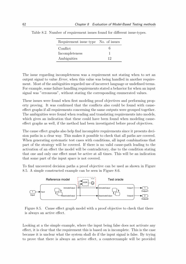
62 Chapter 8 Evaluation of Model-Based Testing methods
Table 8.2. Number of requirement issues found for different issue-types.
Requirement issue type No. of issues
Conflict 6
Incompleteness 1
Ambiguities 12
The issue regarding incompleteness was a requirement not stating when to set anoutput signal to value Error, when this value was being handled in another require-ment. Most of the ambiguities regarded use of incorrect language or undefined terms.For example, some failure handling requirements stated a behavior for when an inputsignal was ”erroneous”, without stating the corresponding enumerated values.
These issues were found when first modeling proof objectives and performing prop-erty proving. It was confirmed that the conflicts also could be found with cause-effect graphs if all requirements concerning the same outputs were grouped together.The ambiguities were found when reading and translating requirements into models,which gives an indication that these could have been found when modeling cause-effect graphs as well, if the method had been investigated before proof objectives.
The cause effect graphs also help find incomplete requirements since it presents deci-sion paths in a clear way. This makes it possible to check that all paths are covered.When generating systematic test cases with conditions, all input combinations thatpart of the strategy will be covered. If there is no valid cause-path leading to theactivation of an effect the model will be contradictory, due to the condition statingthat one and only one effect must be active at all times. This will be an indicationthat some part of the input space is not covered.
To find uncovered decision paths a proof objective can be used as shown in Figure8.5. A simple constructed example can be seen in Figure 8.6.
Reference model Test oracle
1
Output1Input
ActivateOutput
DeactivateOutput
ActivateOutput
DeactivateOutput
Output1
Output2
1
Input 2
Output2
XOR
true
Figure 8.5. Cause effect graph model with a proof objective to check that thereis always an active effect.
Looking at a the simple example, where the input being false does not activate anyeffect, it is clear that the requirement this is based on is incomplete. This is the casebecause it is unclear what the system shall do if the input signal is false. By tryingto prove that there is always an active effect, a counterexample will be provided

8.4 Evaluation 63
{ActivateOutput = true;}
[Input]
1
2
/* Activate output if input is true */
{ ... ActivateOutput = false; ... DeactivateOutput = false; ...}
(a) A simple reference model with anif-statement. It indicates that the ef-fect ActivateOutputs shall become activewhen the input is active. Note that thereis no effect active when the input is notactive.
2
[ActivateOutput]1
{Output1 = true; ...Output2 = true;}
[DeactivateOutput]
{ ...Output1 = false;Output2 = false;}
{Output1 = false; ...Output2 = false;}
(b) The corresponding test oracle. Itactivates and deactivates two output sig-nals based on the cause graph.
Figure 8.6. Reference model and test oracle that exemplifies an incompleterequirement.
stating that the input being false will violate the property. If the model can thenbe verified to match the requirement, the requirement is incomplete (assuming thatthere are no constraints on the input signal).
8.4 Evaluation
For each requirement type an appropriate MBT are proposed, based on the evalua-tion criteria. The result is presented in Table 8.3.
For the operational requirement type a test objective model is most suitable sinceit is the only method that can fully handle this type. It also provides a low modelcomplexity for this specific type.
The proof objective model is most suitable to use for the undesired behavior sinceit provides superior error detectability. The error detection is an advantage whenapplying property proving to other types of requirements as well, but since no testcases can be generated to serve as stimuli for other test systems it fails due to thelower applicability.
As discussed in Section 7.4 no method was used to model latency requirements,instead this could be verified by using a cause-effect graph as an oracle. The re-quirement is verified by allowing a maximum time gap between the oracle and theSUT. However, the model must contain the corresponding requirement(s) statingoutput signal activation and must be used as an test oracle. Since a configurabilityrequirement was not possible to model with any of the methods, none of them werefound to be appropriate.

64 Chapter 8 Evaluation of Model-Based Testing methods
Table 8.3. The proposed choice of MBT method for each requirement type.For latency requirements the cause effect graph is to be used as an observer.None of the MBT methods were found appropriate to use for the configurabilityrequirements.
Method
Requirement typeProof objective
model
Cause effectgraph
Test objectivemodel
Operational XStatic XTemporal XTransition XSequential XUndesired behavior XLatency XConfigurability
The other requirement types, static, temporal, transition and sequential were foundappropriate for use with cause effect graphs. For all these types the method performswell regarding complexity, scalability, modeling time and required skill level. Themethod provides good applicability due to the possibilities for testing in multipleenvironments. It also allows for finding incomplete requirements.
8.5 Discussion
Even though the test objective models are not useful for most of the identified re-quirement types, the test objective block can be a valuable tool when doing propertyproving. This block can be applied to the condition at an implies block to test thatthe implication is not proven valid due to the condition being permanently false.
When error detection is crucial property proving might be more appropriate thancause effect graphs when working in an model environment. An alternative is to havea detailed cause effect graph and use proof objectives to verify equality betweenoracle and model output. For any of these alternatives to be useful for a safetycritical system, target code must be generated from the system model. This is toensure that the code running on the real system is as similar to the model as possibleto create assurance that the property is fulfilled also by the real system.
For a system relying on discrete events, states and sequences the proposed choice ofMBT methods are most likely applicable, with the previously mentioned exceptionfor safety critical behavior.
A system involving more dynamic behavior, such as control systems, the property

8.6 Summary 65
proving is probably the most useful method, due to requirements stating signalproperties instead of values. For example, the requirement ”The output signal shallbe in the range 0-20V”, is more suitable for property proving due to being moreeasily modeled with this method.
Even though some unclear and contradictory requirements were found during thecase study these might also be possible to find by a textual review. However, theywere not found during the textual review thus MBT provides possibilities to findunclear and incomplete requirements.
Blocks incompatible with SLDV analysis was not within the scope, but this wouldmost likely not affect the proposed methods. This since the cause effect graphs werepossible to model with compatible blocks and no system model (that might containincompatible blocks) is used when generating the test cases.
The aspect of system variants was not covered but since Simulinkr provides pos-sibilities for variant handling by selecting a variant subsystem based on a variable,and SLDV can treat this variable as a configuration variable, it is probably possibleto include variants when proving properties and generating test cases.
The proposed requirement types has the benefit of giving rise to similarities whengenerating test cases. This can be useful for further investigations regarding at-tributes and usefulness of automatically generated test cases.
It would also be possible to group the requirements based on their complexity interms of number of signals in the condition and expected outcome. This can bemore useful if investigating computing time for test generation or property proving.
8.6 Summary
Cause-effect graphs were found to be the most appropriate MBT method for allfunctional requirement except the ones regarding undesired behavior. This is mostlybecause of the possibility to apply generated test cases on different test systems andmodel both abstract and concrete requirements.
Test objective models were found to only be appropriate for the operational type,but was also the only method that could handle it properly.
For undesired behavior, property proving with proof objective models was foundmost appropriate due to the excellent error detectability.
The last chapter will present conclusion based on the answers to all research ques-tions and connect to the purpose and objectives presented in Section 1.2.

66 Chapter 8 Evaluation of Model-Based Testing methods

9 CONCLUSION
This thesis have differed from related work by focusing on the actual System UnderTest (SUT) and its requirements. With the selected approach it has been possible toevaluate the usefulness of Model-Based Testing (MBT) and in an industrial contextand give an answer to when and how it is appropriate to use.
Dividing requirements into categories was a decisive factor for the work with theremaining research questions. With the different requirement types it was possibleto present coherent and practical modeling results. With a classification of justfunctional and non-functional requirements this would not have been possible.
The result of modeling requirements was the basis for the evaluation of which model-ing method was the most suitable for each requirement type. Including applicabilityas a criteria elevated the evaluation and gave benefit to test case generation since itapplicability spans the whole development process.
9.1 Improving the development process with Model-Based Testing
The case study confirmed the conclusions made in related works: that MBT canhelp find unclear and ambiguous requirements. When working with proof objectivemodels or cause-effect graphs incomplete, unclear and contradictory requirementswere found, which fulfills Objective 1a. Ambiguous requirements are not only aproblem in the verification process. Formal and concise requirements give the de-velopers a clear target and reduce the risk of unintended behavior occurring in thesystem. This is especially important since implementation errors due to ambiguousrequirements have been shown to be a main problem area. Using a model as a formalspecification is one way of solving this problem.
Creating cause-effect graphs of system behavior and generating test cases can be amore efficient alternative to writing test scripts manually and can help automatethe development process as stated in Objective 2a. Since the test cases are presentin a general form (as vectors with signal values) this introduces opportunities forautomated creation of test scripts. Even though the complete process of movingfrom a generated test case to an executable script was not covered, the area hasbeen investigated and therefore Objective 2b is considered fulfilled.
Modeling of requirements can be initiated at the same time as the first requirementis written. Test design can also be performed at a higher more abstract level by usingcause-effect graphs with abstract events. This allows for starting the design of testsbefore the actual system is designed. It can be concluded that the MBT methods
67

68 Chapter 9 Conclusion
covered by this thesis grants opportunities for testing earlier in the developmentprocess, therefore fulfilling Objective 3a.
Applying MBT together with Model-Based Design (MBD) and Simulinkr can savetime and streamline the verification process. This is partially thanks to the extensiveverification that can be done early in the development process with property provingon software components created in Simulinkr. According to Objective 3b it has beenshown that MBT is possible to apply on multiple test systems in different phases ofthe development, for example proof objectives as observers in a Hardware-In-the-Loop (HiL) rig or with property proving in a model environment.
Requirement models are more abstract than an executable test scripts and are easierto update and modify, therefore models provide possibilities for reuse in comingdevelopment processes, especially for cause-effect graphs with abstract events. Basedon this Objective 3c is considered fulfilled.
Previous research has shown that MBT is useful for generating test cases based oncoverage criteria. However, this thesis can conclude that when generating test casesfor a more complex system these become hard to understand and connect to theintended behavior. Thus automatic test case generation is not useful on its own.Without manually composed test cases or a human that can inspect and verify thecorrectness of the generated test case the connection between the human and theproduct can be lost. This reduces the possibilities for early validation during thedevelopment process.
9.2 Raised questions
This section lists of new problem formulations that where found and not solvedduring the work.
How well implementation errors can be detected by using MBT has only been brieflycovered (finding missing signals with property proving) which is why Objective 1b isnot considered fulfilled. By applying property proving on a larger amount of modelsor running generated test on both models and other test systems, future researchhas the opportunity to fully cover this topic.
Future research could also further cover automatic test case generation accordingto a more functional coverage criteria, as proposed by ”systematic test case genera-tion”. Alternative methods for generating test cases, such as using state charts, andcomparing those to cause-effect graphs is also an interesting topic for future work.
Another raised question is if cause-effect graphs for software components can becombined to model a complete Electronic Control unit (ECU) and how the combinedbehavior then can be limited.

9.2 Raised questions 69
How to execute a test generated by Simulinkr Design Verifier� (SLDV) in a HiLtesting environment is also a raised question. Possibilities that have been stumbledupon are: generating an executable test script from the SLDV test case or runningthe test case in a Simulinkr environment connected to a HiL environment.
Finally it can be concluded that when selecting an appropriate MBT method it isvaluable to analyze the types of requirements and behavior of the SUT.

70 Chapter 9 Conclusion

Bibliography
Allenby, K. and Kelly, T. (2001). Deriving safety requirements using scenarios. In:Requirements Engineering, 2001. Proceedings. Fifth IEEE International Sym-posium on. pp 228–235.
Apfelbaum, Larry and Doyle, John (1997). Model based testing. In: Software QualityWeek Conference. pp 296–300.
Bringmann, E. and Kramer, A. (2008). Model-based testing of automotive systems.In: Software Testing, Verification, and Validation, 2008 1st International Con-ference on. pp 485–493.
Broy, M., notes in computer science (e-book collection), Lecture and (e-book collec-tion), SpringerLink (2005). Model-based testing of reactive systems: advancedlectures. vol. 3472. Springer. Berlin.
Broy, Manfred, Sascha, Kirstan, Helmut, Krcmar and Bernhard, Schtz (2012). Whatis the benefit of a model-based design of embedded software systems in the carindustry?. In: Emerging Technologies for the Evolution and Maintenance ofSoftware Models. pp 343–369. IGI Global.
Chen, Chunqing, Sun, Jun, Liu, Yang, Dong, Jin S. and Zheng, Manchun (2012).Formal modeling and validation of stateflow diagrams. International Journalon Software Tools for Technology Transfer, 14(6), 653–671.
Chung, Lawrence and Prado Leite, Julio Cesar (2009). Conceptual modeling: Foun-dations and applications. Chap. On Non-Functional Requirements in SoftwareEngineering, pp 363–379. Springer-Verlag. Berlin, Heidelberg.
Etienne, J.-F., Fechter, S. and Juppeaux, E. (2010). Using simulink design verifierfor proving behavioral properties on a complex safety critical system in theground transportation domain. In: Complex Systems Design & Management,Marc Aiguier, Francis Bretaudeau and Daniel Krob (Eds.). pp 61–72. SpringerBerlin Heidelberg.
Friedman, J. (2006). Matlab/simulink for automotive systems design. In: Design,Automation and Test in Europe, 2006. DATE ’06. Proceedings. vol. 1. pp 1–2.
Gibbs, Samuel (2014). Google’s self-driving car: How doeas it work and when canwe drive one?. The Guardian29 May 2014 Available: http://gu.com/p/3ptht[Accessed: 2014-05-30].
Glinz, M. (2007). On non-functional requirements. In: Requirements EngineeringConference, 2007. RE ’07. 15th IEEE International. pp 21–26.
71

Hanselmann, Herbert (2008). Challenges in automotive software engineering. In:28th International Conference on Software Engineering : proceedings : 20-28May 2006, Shanghai, China. ACM. pp 888–888.
Hull, Elizabeth, Jackson, Ken, Dick, Jeremy and (e-book collection), SpringerLink(2011). Requirements engineering. Springer. London.
ISO/IEC (2001). Software engineering – product quality – part 1: Quality model.ISO/IEC 9126-1:2001. International Organization for Standardization. Geneva,Switzerland.
ISO/IEC (2011). Systems and software engineering – systems and software qualityrequirements and evaluation (square) – system and software quality models.ISO/IEC 25010:2011. International Organization for Standardization. Geneva,Switzerland.
Lee, Chien-Chang and Friedman, Jon (2013). Requirements modeling and au-tomated requirements-based test generation. SAE International Journal ofAerospace, 6(2), 607–615.
Li, Meng and Kumar, R. (2012). Model-based automatic test generation forsimulink/stateflow using extended finite automaton. In: Automation Scienceand Engineering (CASE), 2012 IEEE International Conference on. pp 857–862.
Micskei, Z. and Majzik, I. (2006). Model-based automatic test generation for event-driven embedded systems using model checkers. In: Dependability of Com-puter Systems, 2006. DepCos-RELCOMEX ’06. International Conference on.pp 191–198.
Mohalik, Swarup, Gadkari, Ambar A., Yeolekar, Anand, Shashidhar, K.C. andRamesh, S. (2014). Automatic test case generation from simulink/stateflowmodels using model checking. Software Testing, Verification and Reliability,24(2), 155–180.
Pretschner, A., Prenninger, W., Wagner, S., Khnel, C., Baumgartner, M., Sostawa,B., Zlch, R. and Stauner, T. (2005). One evaluation of model-based testing andits automation. In: Proceedings of the 27th international conference on softwareengineering. ACM. pp 392–401.
Stecklein, Jonette M., Dabney, Jim, Dick, Brandon, Haskins, Bill, Lovell, Randyand Moroney, Gregory (2004). Error cost escalation through the project lifecycle. Technical report.
The MathWorks Inc (2013). Simulink Design Verifier 2 User’s Guide.
The MathWorks Inc (2014). Model-based testing. http://www.mathworks.se/
discovery/model-based-testing.html [Accessed: 2014-01-20].
The MathWworks Inc (2013). Simulink Verification and Validation User’s Guide.
72

Utting, Mark, Legeard, Bruno and (e-book collection), ScienceDirect (2007). Prac-tical model-based testing: a tools approach. Morgan Kaufmann Publishers. Am-sterdam.
Volvo Car Group (2013). Volvo car group initiates world unique swedish pilot projectwith self-driving cars on public roads. Press Release. https://www.media.
volvocars.com/global/en-gb/download/136182/pdf/pdf.
Wahler, M., Ferranti, E., Steiger, R., Jain, R. and Nagy, K. (2012). Cast: Automat-ing software tests for embedded systems. In: Software Testing, Verification andValidation (ICST), 2012 IEEE Fifth International Conference on. pp 457–466.
Weber, M. and Weisbrod, J. (2003). Requirements engineering in automotive devel-opment: experiences and challenges. Software, IEEE, 20(1), 16–24.
Zander, Justyna, Schieferdecker, Ina, Mosterman, Pieter J. and (e-book collection),CRCnetBASE (2011). Model-based testing for embedded systems. CRC Press.Boca Raton, Fla.
Zander-Nowicka, J (2009). Model-based Testing of Real-Time Embedded Systems inthe Automotive Domain. Fraunhofer IRB Verlag. Berlin.
73

74

Appendix A
Modeling guidelines
This appendix presents some guidelines regarding modeling when using Simulinkr
Design Verifier�. Where statements about the impact on computing time are made,the corresponding actions are not thoroughly investigated and might not be benefi-cial for other cases than the one presented in this thesis.
Matlab 2012b with the following toolboxes were used:
� Simulinkr version 8.0
� Stateflowr version 8.0
� Simulinkr Design Verifier� version 2.3
� Simulinkr Verification and Validation� version 3.4
General tips
When using extenders and detectors, be sure to provide external reset to avoidoutput being held true even when conditions are not met.
The detector in the SLDV library supplies the number of time steps from the maskto the underlying MATLABr function as an int8. This significantly reduces thepossible number of time steps that are detectable. Since the underlying MATLABr
function instead uses an int16 this can be fixed my making a copy if the block andchanging the variable type in the mask. This problem was reported to MathWorksand might be corrected in later versions of SLDV.
A property stating that an integer signal shall be zero, which is a common value forOff, or that a boolean signal shall be false for some condition, can lead to a propertybeing proven valid if this signal is not connected. For example, the properties shownin Figure A.1 can be proven satisfied if the two output signals are not connected.
75

1
Output_Int
true
== Signal_Off
A
BA ==> B
2
InputSignal
3
Output_Bool
trueA
BA ==> B
4
InputSignal1
NOT
Figure A.1. Example properties which can be proven satisfied if the signalsOutput Int or Output Bool are not connected
Computing time
When computing times are long and objectives still are undecided, try the methodpresented in:http://www.mathworks.se/help/sldv/ug/prove-properties-in-large-models.
html
Use integers instead of doubles as far as possible to significantly reduce computingtime for property proving.
Avoid using the clock block to reduce computing time.
Removing dead logic before property proving can reduce computing time.
Increasing the sampling time based on the lowest used timing parameter (e.g. usedin a detector block) can reduce computing time significantly. The sampling timeshould be set as long as the shortest timing parameter but short enough so that noextender or detector block gets an output duration of zero.
Decoupling an input signal where only specific values shall be used in a Stateflowr
chart can reduce computing time. E.g. if the chart only uses VehicleModeRunning,it can be more efficient to check the value of VehicleMode outside the chart and onlyhave a boolean input, as exemplified in Figure A.2.
VehicleModeRunning Out
Stateflow Chart
1
VehicleMode
1
Out
== VehicleModeRunning
Figure A.2. Creating a boolean input to a Stateflow chart instead of makingthe check inside of the chart. This can reduce computing time when performingproperty proving
Using a MATLABr chart instead of the standard Stateflowr chart often leads tosignificant increases in computing time performing property proving.
76

Appendix B
Systematic test case generation
The following type of structure was used when generating systematic test cases:
1
VehicleMode
VehicleMode_Hibernate
VehicleMode_Parked
VehicleMode_Living
VehicleMode_Accessory
VehicleMode_PreRunning
VehicleMode_Cranking
VehicleMode_Running
3
MainBeamStalkPosition
2
LightMode
LCP_Status
MainBeamStalkPosition
TestStrategy
1
LCP_Status LCP_Status_Park
LCP_Status_Drive
LCP_Status_DrivePlus
LCP_Status_ZeroDRL
LCP_Status_ZeroDRL
LCP_Status_Park
LCP_Status_Drive
LCP_Status_DrivePlus
MainBeamStalkPosition
TestStrategy
2
MainBeamStalkPosition
LIN_MainBeam_StalkStatus_1_NeutralRestingPosition
LIN_MainBeam_StalkStatus_1_FlashToPass1
MainBeamStalkPosition
LIN_MainBeam_StalkStatus_1_ToggleMainBeam
Figure B.1. Test strategy for generation of a systematic test case.
The following MATLABr code was created to generate systematic test cases.
AutoHarness Strategy.m
function [status, fileList] = ...AutoHarness Strategy( path , init, separateTestCases)
%Inputs: Path to a TestStrategy subsystem
%Filesfilename = [bdroot(gcb) 'AutoHarness.slx'];filename temp = [bdroot(gcb) 'AutoHarness temp.slx'];file = [pwd '\' filename];
%SLDV Options
77

opts = sldvoptions;opts.Mode = 'TestGeneration';opts.ModelCoverageObjectives = 'mcdc';%opts.ModelCoverageObjectives = 'ConditionDecision';opts.TestSuiteOptimization = 'CombinedObjectives';opts.OutputDir = ['autoharness' bdroot(gcb)];if(separateTestCases)
opts.SaveHarnessModel = 'on';opts.SaveDataFile = 'off';
elseopts.SaveHarnessModel = 'off';opts.SaveDataFile = 'on';opts.SaveExpectedOutput = 'on';longTestFile = [pwd '\' 'autoharness' bdroot(gcb) '\'...
bdroot(gcb) ' LongTestCase.mat'];%Used when creating harness from sldvDataharnessopts = sldvharnessopts;harnessopts.harnessFilePath = file;harnessopts.modelRefHarness = false;
end
opts.DisplayReport = 'off';opts.HarnessModelFileName = filename temp;%get(opts)
fileList={};
constraintBlockName = 'req';strategyBlockName = 'TestStrategy';
%Remove the final Harness file if this is the first function callif(init)
if exist(file, 'file')delete(file);
endend
SysList = find system(path,'SearchDepth',1,'BlockType','SubSystem');
%Find systems at current level (not at higher levels)SysListCurrentDepth = strrep(SysList,path,'');constraintIndex = ~cellfun(@isempty,strfind...
(SysListCurrentDepth,constraintBlockName));constraintPath = SysList(constraintIndex);constraintNum = length(constraintPath);
%Deactivate all constraints (precaution)for i = 1:constraintNum
set param(constraintPath{i},'enabled','off')end
% activate one by onefor i = 1:constraintNum
set param(constraintPath{i},'enabled','on')
78

%Find next level of TestStrategy subsystem(s) at current levelstrategyIndex = ~cellfun(@isempty,...
strfind(SysListCurrentDepth,strategyBlockName));strategyPath = SysList(strategyIndex);
%Loop through all strategy subsystems, if length(strategyPath) is zero,%we are at the bottom level of the branch
if(isempty(strategyPath))%Generate test cases[status,filenames] = sldvrun(bdroot(gcb), opts, true);
%Check that a test case was generated%(since status, is not zero for contradictory model)%load(filenames.DataFile)%if (status) %If constraints are not contradictory
delete(filenames.LogFile)
%Save file name (for merge at last return)if(separateTestCases)
close system([opts.HarnessModelFileName '/Inputs'], 0)close system(filenames.HarnessModel, 1)fileList = [fileList ; filenames.HarnessModel];
elsefileList = [fileList ; filenames.DataFile];
end%end
elsefor j=1:length(strategyPath)
%Recursive call to activate next TestStrategy subsystem[status, List] = AutoHarness Strategy(strategyPath{j},...
false,separateTestCases);if(~status)
returnendfileList = [fileList ; List];
endend
set param(constraintPath{i},'enabled','off')end
disp(['TestStrategy completed: ' path])
if(init)%If about to exit first function call
if(separateTestCases)sldvmergeharness(file, fileList);
close system([file '/Inputs'], 0)close system(file, 1)
elseMakeLongTestCase(fileList, longTestFile);
79

sldvmakeharness(bdroot(gcb),longTestFile,harnessopts);end
delete([opts.OutputDir '/' bdroot(gcb) 'AutoHarness temp*'])endstatus = true;end
MakeLongtestCase.m
function MakeLongTestCase(sldvDataFileList, fileName)
load(sldvDataFileList{1})
%Copy sldvData to obtain correct structsldvDataLong = sldvData;sldvDataLong.TestCases = sldvDataLong.TestCases(1,1);%Clear testcasesldvDataLong.TestCases(1,1).timeValues = [];sldvDataLong.TestCases(1,1).dataValues = ...
cell(size(sldvDataLong.TestCases(1,1).dataValues));sldvDataLong.TestCases(1,1).expectedOutput = ...
cell(size(sldvDataLong.TestCases(1,1).expectedOutput));
Ts = sldvData.AnalysisInformation.SampleTimes;
%Combine test casesfor i=1:length(sldvDataFileList)
load(sldvDataFileList{i})%Check if a testcase exists (no test case if e.g. contradictory model)if(isfield(sldvData,'TestCases'))
for j=1:length(sldvData.TestCases)%Extend existing timeValues with new that are moved forward in timeif(i==1 && j==1) %If this is the first tc, just copey timeValues
sldvDataLong.TestCases(1,1).timeValues = ...sldvData.TestCases(1,j).timeValues;
elsesldvDataLong.TestCases(1,1).timeValues = ...
[sldvDataLong.TestCases(1,1).timeValues ...sldvData.TestCases(1,j).timeValues + ...sldvDataLong.TestCases(1,1).timeValues(end)+Ts];
end
%Extend dataValuesfor k=1:length(sldvData.TestCases(1,j).dataValues)sldvDataLong.TestCases(1,1).dataValues{k} = ...
[sldvDataLong.TestCases(1,1).dataValues{k} ...sldvData.TestCases(1,j).dataValues{k}];
end
%Extend expectedOutputfor k=1:length(sldvData.TestCases(1,j).expectedOutput)sldvDataLong.TestCases(1,1).expectedOutput{k} = ...
80

[sldvDataLong.TestCases(1,1).expectedOutput{k} ...sldvData.TestCases(1,j).expectedOutput{k}];
endend
end
endsave(fileName,'sldvDataLong')
end
81


![Filmstripping and Unrolling: A Comparison of Veri cation ... · model [14], i.e. an equivalent UML/OCL description in which all behavioral model elements and the veri cation task](https://img.pdfslide.us/doc/110x75/5d50380088c993f62d8b72cf/filmstripping-and-unrolling-a-comparison-of-veri-cation-model-14-ie.jpg)