Embed Size (px)
Citation preview
Evaluation of a prototype MinifiedAugmented-View device for patientswith impaired night vision*
Alex R. Bowers1, Gang Luo1, Noa M. Rensing2 and Eli Peli1
1The Schepens Eye Research Institute and Harvard Medical School, Boston, MA, and 2MicroOptical
Engineering Corporation, Westwood, MA, USA
Abstract
An evaluation was carried out of the first prototype (LV-3) of a new night vision device, which
incorporates visual field expansion through minification (Minified Augmented-View), to provide
feedback for continuing development. Six subjects with night blindness completed visual function
measurements and indoor mobility assessments without a device, with the LV-3 and with a
commercially available comparison device (the Multi-Vision) at light levels representative of well lit
and poorly lit streets. Device performance and potential benefits in real-world situations were
evaluated at four outdoor locations (well lit to very dark). Results indicate that the see-through nature
and spectacle-frame mounting of the LV-3 address some of the cosmetic and ergonomic
disadvantages of currently available devices; however insufficient light sensitivity of the prototype
camera limited LV-3 performance. With improved camera sensitivity and full implementation of the
Minified-Contours Augmented-View concept in the next prototype, patients might be able to make
better use of the novel field expansion and vision multiplexing features to aid outdoor night mobility.
Keywords: augmented reality, field expander, head mounted device, mobility performance, night
blindness, retinitis pigmentosa
Introduction
Night blindness (impaired vision at low light levels) isthe hallmark of any disease that affects rod photore-ceptor function, for example retinitis pigmentosa, cho-roideraemia and congenital stationary night blindness(Kanski, 2003). Typically the impairment is first noticedoutdoors at night or in very dark indoor areas, evenwhen vision under photopic conditions may still berelatively unaffected. Mobility performance of patientswith night blindness is adversely affected by reducedillumination (Black et al., 1996; Geruschat et al., 1998),
causing major difficulties with independent night mobil-ity (Turano et al., 1999) and limiting participation inactivities requiring outdoor night travel.
Since the early 1970s, various night vision enhance-ment devices have been proposed as aids for patientswith night blindness. At first devices were based onmilitary light-intensifier technology and were large, handheld (although a canvas head mount was developed),monocular and heavy (Berson et al., 1973a). Althoughlighter, more compact, versions were developed (Bersonet al., 1973b, 1974; Hoover, 1983; Morrissette et al.,1983), they were still monocular with a monochromaticgreen display, and met with poor user acceptance(Morrissette et al., 1983). More recently there has beenrenewed interest in the development of lightweight,binocular, head mounted, goggle-type devices usinglow-light sensitive video cameras (Friedburg et al.,1999; Rohrschneider et al., 2000; Spandau et al., 2002).However these newer binocular devices are conspicuous,cosmetically unattractive, prevent eye contact, and havea relatively limited field of view (about 30–40�), althoughthey do improve night mobility in outdoor environments(Rohrschneider et al., 2000; Spandau et al., 2002).
Received: 26 January 2004
Revised form: 30 April 2004
Accepted: 6 May 2004
*This paper was presented at the UK Multi-disciplinary Low Vision
Rehabilitation and Research Conference held at Aston University,
December 2003.
Correspondence and reprint requests to: Alex Bowers, The Schepens Eye
Research Institute, 20 Staniford Street, Boston, MA 02114, USA.
Tel.: 1 617 912 2512; Fax: 1 617 912 0111.
E-mail address: [email protected]
Ophthal. Physiol. Opt. 2004 24: 296–312
ª 2004 The College of Optometrists296
MicroOptical Engineering Corporation and the Sche-pens Eye Research Institute are collaborating in thedevelopment of an innovative night vision device forpatients with night blindness. The long-term aim is toimplement Peli’s Minified-Contours Augmented-Viewconcept (Peli, 2001; Vargas-Martin and Peli, 2002),using a novel display technology developed by Micro-Optical. New display technology allows embedding of amicro-display and its optical viewing system in aspectacle frame and lens (Spitzer et al., 1998), thusenabling the development of a spectacle-mounted devicewhich has the potential to be cosmetically moreattractive and less conspicuous than other currentlyavailable night vision devices. If the display is turnedoff, the glasses will function as ordinary eyewear with noobscuration of the visual field (except for a smallreduction in light transmission in the display area). Asthe display is see-through and monocular, the user willhave a natural view of the scene at all times (in additionto the display image), whereas in existing commerciallyavailable devices, users see only the image-intensifiedview of the scene presented on a opaque display withinthe goggles. The spectacle-mounted design will alsopermit normal eye contact, an important part of socialinteraction, if the user encounters other people whilewearing the device.Many patients with night blindness also have restric-
ted peripheral visual fields. Their mobility difficulties arenot only because of reduced sensitivity at night, but alsothe field restriction. Even in daylight, a patient with 20�(diameter) or less of residual visual field will encountermobility difficulties (Black et al., 1996; Haymes et al.,1996; Geruschat et al., 1998). Visual field expansion canbe achieved through minification; although the minifi-cation reduces resolution, the field expansion providesvisual information about objects that would otherwisebe outside the patient’s visual field. Berson et al. (1974)reported an improvement in mobility performanceunder scotopic conditions for two subjects with nightblindness and visual fields of <10� when a wide-angle(fish-eye) lens was attached to the objective of aGeneration II night vision pocketscope, providing fieldexpansion of 4–5·. However, to the best of ourknowledge, visual field expansion has not been imple-mented in any commercial products.The Augmented-View concept to be implemented in
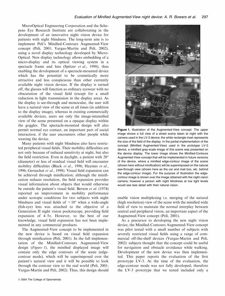
the new device is based on visual field expansionthrough minification (Peli, 2001). In the full implemen-tation of the Minified-Contours Augmented-Viewdesign (Figure 1), the minified displayed image willcontain only the edge contours of the scene (edge-contour mode), which will be superimposed over thepatient’s natural view and it will be possible to lookthrough the contour view to the real world (Peli, 2001;Vargas-Martin and Peli, 2002). Thus, this design should
enable vision multiplexing i.e. merging of the natural(high resolution) view of the scene with the minified widefield of view to maintain the normal interplay betweencentral and peripheral vision, an important aspect of theAugmented-View concept (Peli, 2001).
As a precursor to developing the new night visiondevice, the Minified-Contours Augmented-View conceptwas pilot tested with a small number of subjects withseverely restricted visual fields using a range of com-mercial off-the-shelf devices (Vargas-Martin and Peli,2002): subjects thought that the concept could be usefulfor navigation and obstacle avoidance while walking.Development of the new device was then implemen-ted. This paper reports the evaluation of the firstprototype LV-3. At the time of the evaluation, theedge-contour mode was not fully developed; thereforethe LV-3 prototype that we tested included only a
Figure 1. Illustration of the Augmented-View concept. The upper
image shows a full view of a street scene taken at night with the
camera used in the LV-3 device; the white rectangle inset represents
the size of the field of the display. In the partial implementation of the
concept (Minified Augmented-View) used in the prototype LV-3
device, a minified gray-scale image of this scene was presented on
the device display. The lower image shows the Minified-Contours
Augmented-View concept that will be implemented in future versions
of the device, where a minified edge-contour image of the scene
(shown here without minification) will be superimposed on the natural
see-through view (shown here as the car and mail box, etc. behind
the edge-contour image). For the purpose of illustration the edge-
contour image is shown over the image obtained with the night vision
camera; however a person with night blindness at low light levels
would see less detail with their natural vision.
Evaluation of Minified Augmented-View night device: A. R. Bowers et al. 297
ª 2004 The College of Optometrists

partial implementation of the Augmented-View concept,displaying a gray-scale minified image rather than anedge-contour image (i.e. a Minified Augmented-View,rather than a Minified-Contours Augmented-View).Although we were unable to evaluate the edge-contourmode, it was nevertheless important to obtain feedbackon cosmetic, ergonomic, and functional aspects of thedevice in order to guide further development of the finalprototype LV-4. Furthermore, in the LV-4 prototypethe option of using either the edge-contour mode or thegray-scale image mode is planned; therefore it was usefulto obtain preliminary feedback on the utility of the gray-scale image.
The gray-scale mode provides a complete minifiedimage superimposed on the natural view of the scene,whereas the edge-contour mode superimposes only aminified outline on the natural view (Figure 1). Thus invery dark areas, where natural vision of patients withnight-blindness is non-functional, the gray-scale imagemight be preferred as it provides more informationthan the edge-contour image. Also, under these con-ditions, the LV-4 in gray-scale mode could operate asa conventional night vision device using digital zoom-ing to achieve a 1:1 image. While the gray-scale imageis not totally opaque, it might be difficult to seethrough this type of image at low light levels.Therefore, in the LV-3 prototype, vision multiplexingmay be achieved by alternating attention between thetwo eyes, or by using slight head movement to shiftthe display eye out of the field of the gray-scale image(temporal multiplexing, as in the use of bioptic lowvision telescopes).
In order to provide a meaningful assessment of theLV-3 prototype, the evaluation was carried out atfunctionally relevant illumination levels using subjectswith night blindness. The evaluation included assessmentof visual function, mobility on an indoor obstacle course,and outdoor observations with and without the device.To provide valid comparison data, subjects also com-pleted all evaluations using a commercially available,binocular goggle-type night vision device (Multi-Vision,Trivisio, Switzerland). Early versions of this device(Rohrschneider et al., 2000; Spandau et al., 2002) andrecent versions, similar to that used in this study
(Pierrottet et al., 2003; Hartong et al., 2004), werefound to improve night mobility in patients with nightblindness.
Methods
The evaluation included clinical vision tests performedunder different illumination levels with and without adevice, an indoor obstacle course under two lowillumination levels, and an outdoor stationary deviceevaluation at night. The indoor and outdoor assess-ments were carried out on separate days (with theexception of one subject) and the order of assessmentsvaried between subjects.
Subjects
Six patients with night blindness participated in thisstudy (Table 1). All subjects were in good generalhealth, with no physical or mobility restrictions thatwould impair their ability to participate in the study.Subjects 1–5 first became aware of night blindness morethan 20 years ago, used long canes for day and nightmobility and all engaged in independent night mobility.Subject 6 became aware of night blindness more recently(6 years ago), and neither used a long cane nor engagedin independent night mobility. Before the study com-menced, subjects read and signed an informed consentform approved by the Institutional Review Board(IRB).
Night vision devices
Two night vision devices were evaluated: the firstgeneration prototype LV-3 of the new night visiondevice (MicroOptical Engineering Corp, MA, USA),and a commercially available comparison device, theMulti-Vision (M-V).
The prototype LV-3 system implemented the MinifiedAugmented-View concept (as described in the introduc-tion), by presenting a minified view of the ambient sceneobtained with a wide-angle camera. The system consis-ted of a pair of glasses integrated with an opticalsee-through monocular display (90 g) and a control unit
Table 1. Subject details. Vision data are baseline measures at standard illumination levels
Subject Age Gender Diagnosisa
Corrected visual
acuity (logMAR)
Contrast sensitivity
(log unit)
Visual field horizontal
diameter (degree)
Independent night
mobility
1 50 M RP 0.32 1.35 7.5 Yes
2 62 M RP 0.02 1.65 10.5 Yes
3 40 M Choroideraemia 0.16 1.60 9.9 Yes
4 46 F RP 0.04 1.85 19.8 Yes
5 68 M RP 0.22 1.35 11.3 Yes
6 26 F RP 0.24 1.60 18.3 No
aRP, retinitis pigmentosa.
298 Ophthal. Physiol. Opt. 2004 24: No. 4
ª 2004 The College of Optometrists
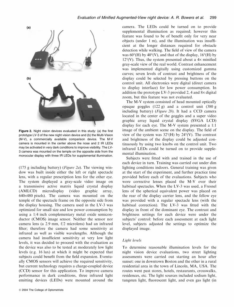
(175 g including battery) (Figure 2a). The viewing win-dow was built inside either the left or right spectaclelens, with a regular prescription lens for the other eye.The system displayed a gray-scale video image ona transmissive active matrix liquid crystal display(AMLCD) microdisplay (video graphic array,640·480 pixels). The camera was mounted on thetemple of the spectacle frame on the opposite side fromthe display housing. The camera used in the LV-3 wasoptimized for small size and low power consumption byusing a 1/4 inch complementary metal oxide semicon-ductor (CMOS) image sensor. Neither the sensor norcamera lens (a 2.9 mm, f/2 microlens) had an infraredfilter; therefore the camera had some sensitivity atinfrared as well as visible wavelengths. Although thecamera had insufficient sensitivity at very low lightlevels, it was decided to proceed with the evaluation asthe device was also to be tested at moderately low lightlevels (e.g. 16 lux) at which it might be expected thatsubjects could benefit from the field expansion. Eventu-ally CMOS sensors will achieve the required sensitivity,but current technology requires a charge-coupled device(CCD) sensor for this application. To improve cameraperformance in dark conditions, three infrared lightemitting devices (LEDs) were mounted around the
camera. The LEDs could be turned on to providesupplemental illumination as required; however thisfeature was found to be of benefit only for very nearobjects (under 1 m), and the illumination was insuffi-cient at the longer distances required for obstacledetection while walking. The field of view of the camerawas 60�(H) by 40�(V), and that of the display, 16�(H) by12�(V). Thus, the system presented about a 4· minifiedgray-scale view of the real world. Contrast enhancementwas implemented digitally using customized gammacurves; seven levels of contrast and brightness of thedisplay could be selected by pressing buttons on thecontrol unit. All electronics were digital (direct camerato display interface) for low power consumption. Inaddition the prototype LV-3 provided 2, 4 and 8· digitalzoom, but this feature was not evaluated.
The M-V system consisted of head mounted opticallyopaque goggles (122 g) and a control unit (380 gincluding battery) (Figure 2b). It had a CCD cameralocated in the center of the goggles and a super videographic array liquid crystal display (SVGA LCD)display for each eye. The M-V system presented a 1:1image of the ambient scene on the display. The field ofview of the system was 32�(H) by 24�(V). The contrastand brightness of the display could be adjusted con-tinuously by using two knobs on the control unit. Twoinfrared LEDs could be turned on to provide supple-mental illumination.
Subjects were fitted with and trained in the use ofeach device in turn. Training was carried out under dimlighting conditions indoors. General training was givenat the start of the experiment, and further practice timeprovided before each of the evaluations. Subjects whowore corrective lenses placed the M-V over theirhabitual spectacles. When the LV-3 was used, a Fresnellens of the spherical equivalent power was placed onthe rear of the display carrier lens, and the fellow eyewas provided with a regular spectacle lens (with thehabitual correction). The LV-3 was fitted with thedisplay in front of the dominant eye. The contrast andbrightness settings for each device were under thesubjects� control: before each assessment at each lightlevel, subjects adjusted the settings to optimize thedisplayed image.
Light levels
To determine reasonable illumination levels for thenight vision device evaluations, two street lightingassessments were carried out starting an hour aftersunset: one in downtown Boston and the other in a ruralresidential area in the town of Lincoln, MA, USA. Theroutes went past stores, hotels, restaurants, crosswalks,residences, etc. The light sources included sodium light,tungsten light, fluorescent light, and even gas light (in
(a)
(b)
Figure 2. Night vision devices evaluated in this study: (a) the first
prototype LV-3 of the new night vision device and (b) the Multi-Vision
(M-V), a commercially available comparison device. The M-V
camera is mounted in the center above the nose and 2 IR LEDs
may be activated in very dark conditions to improve visibility. The LV-
3 camera was mounted on the temple on the opposite side from the
monocular display with three IR LEDs for supplemental illumination.
Evaluation of Minified Augmented-View night device: A. R. Bowers et al. 299
ª 2004 The College of Optometrists
the historic Beacon Hill area of Boston). An illuminancemeter (Minolta TL-1, Minolta Corp., Ramsey, NJ,USA) was used to measure the lighting conditions.Measurements were taken about every 15 m with theilluminance meter held face up 1 m above the ground. Intotal, 342 points were measured in the two locations.
The illuminance level data were analysed by dividingthe surveyed areas into three categories: busy well-litshopping streets (downtown), quiet poorly-lit residentialstreets (downtown), and rural residential areas. Table 2summarizes the results. Based on these results, 16 and2 lux were selected as the two main low light levels forconducting the vision tests and the indoor mobilityassessments. These light levels were chosen to be repre-sentative of those typically found on the well lit andpoorly lit streets at night in the Boston area (highand mid/low mesopic respectively); they were alsoincluded in the four light levels used in the outdoorassessment (described below). Lower light levels will alsobe encountered during outdoor night travel, especially inrural areas (Table 2); therefore one location with illu-mination below 1 lux was included in the outdoorassessment and indoor mobility was also assessed invery dark conditions (<0.1 lux; scotopic), wherepatients with night blindness have virtually no vision.
Vision tests
The visual acuity, contrast sensitivity, and visual field ofthe subjects were measured under three light levels.Baseline measurements were conducted without nightvision devices at standard illumination levels (EarlyTreatment for Diabetic Retinopathy Study (ETDRS)lighting cabinet illumination for visual acuity andcontrast sensitivity, and office overhead fluorescentillumination for visual field measurements). All visionmeasurements were also taken under the two low lightlevels (16 and 2 lux) with and without each night visiondevice. Measurements with the LV-3 were taken formonocular viewing of the gray-scale display image. Acover was placed over the front of the display lens toensure that only information from the display image(and not the see-through carrier lens) was available,while the fellow eye was occluded. Measurements withthe M-V device were taken under binocular viewingconditions.
Visual acuity was measured with ETDRS visual acuitycharts from 4 m, except when subjects were wearing theLV-3, when they were at 1 m so that several lines on thechart could be read on the minified display image. Lettercontrast sensitivity was measured with Pelli-Robsoncharts at 1 m. Three different acuity charts and twoPelli–Robson charts were used to prevent memorization.Visual acuity charts and Pelli–Robson charts were hungin an ETDRS cabinet. They were illuminated either bythe original fluorescent light for standard ETDRS lightlevel (750 lux), or by four additional tubular incandes-cent lights, which were controlled by a dimmer, toprovide the low light levels tested.
Visual field extent was measured at 1 m on a blacktangent screen. A 10 mm white target was used forstandard tests (without night vision device understandard office illuminance) and M-V tests, but ahomemade 40 mm target was used for LV-3 tests tocompensate for the 4·-minified display. The standardoffice light level was provided by ceiling recessedfluorescent room lights (375 lux) and low light levelswere achieved by adjusting dimmer-controlled ceilingrecessed incandescent lights.
Indoor mobility assessment
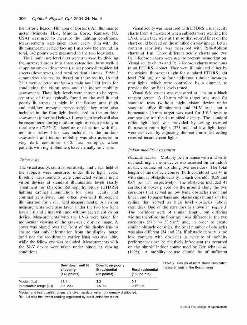
Obstacle course. Mobility performance with and with-out each night vision device was assessed on an indoorobstacle course set up along two corridors. The totallength of the obstacle course (both corridors) was 44 mwith similar obstacle density in each corridor (0.59 and0.69 per m2, respectively). The obstacles included 41cardboard boxes placed on the ground along the twocorridors that served as low lying obstacles (foot andknee), and 16 paper bags and plastic cups hung from theceiling that served as high level obstacles (aboveshoulder). One of the corridors is shown in Figure 3.The corridors were of similar length, but differingwidths; therefore the floor area was different in the twocorridors (57.6 vs 33.5 m2) and, in order to createsimilar obstacle densities, the total number of obstacleswas also different (34 and 23). If obstacle density is toolow, contacts with obstacles (a measure of mobilityperformance) can be relatively infrequent (as occurredon the �simple� indoor course used by Geruschat et al.(1998)). A mobility course should be of sufficient
Table 2. Results of night street illumination
measurements in the Boston areaDowntown well lit
shopping
(145 points)
Downtown poorly
lit residential
(52 points)
Rural residential
(162 points)
Median (lux) 13.1 3.3 0.3
Interquartile range (lux) 6.5–22.4 1.5–6.9 0.1a–0.5
Median and interquartile ranges are given as data were not normally distributed.a0.1 lux was the lowest reading registered by our illuminance meter.
300 Ophthal. Physiol. Opt. 2004 24: No. 4
ª 2004 The College of Optometrists
complexity to challenge performance such that differ-ences between subjects and conditions are discernible(Haymes et al., 1996). An obstacle density that washigher than anything that might be encountered in anatural environment was therefore chosen, but this wassimilar to that used in a previous indoor mobility studyof subjects with retinitis pigmentosa, in which there weresignificant differences in contact numbers at high(360 lux) and low (25 lux) illumination levels (Blacket al., 1996), and was similar to the density used in otherindoor studies where vision variables affected mobilityperformance (Pelli, 1986; Lovie-Kitchin et al., 1990;Kuyk et al., 1998). The illumination levels in bothcorridors could be adjusted by using a group of dimmercontrolled incandescent lights. For each walk along thecourse, the lighting was set with the median illuminanceat 16 lux in one corridor and 2 lux in the other.Each subject walked the complete course three times
(once without and once with each of the devices) inalternate directions (to reduce the effect of memoriza-tion). Device condition (without device, with M-V orLV-3 device), illumination level in each corridor (16 or
2 lux) and direction of walking were counterbalanced(as far as possible) across subjects. Subjects completedthe mobility assessments without long canes. Beforewalking the obstacle course with a device, subjectswere given limited practice (5–15 min) walking aroundseveral similar obstacles laid out in a separate roomunder dimly lit conditions. At the start point of eachcorridor, subjects were given sufficient time to adjust thecontrols of the night vision device (when with device) orto adapt to the ambient illumination (when withoutdevice). Subjects were instructed to walk to the far endof each corridor (until told to stop) avoiding contactwith all obstacles and with the corridor walls. Aninvestigator followed close behind a subject at all timesto ensure safety.
Mobility performance was assessed by recording timeto walk along each corridor and the number of contactswith obstacles. Touching the walls was also recorded asa contact. At the end of each walk, subjects were askedto rate on a 5-point scale perceived difficulty withrecognizing objects, determining obstacle distance,determining obstacle position (left or right), and avoid-ing obstacles in each corridor.
Walking times, measured with a stopwatch, wereconverted to walking speeds and expressed as a per-centage of the subject’s preferred walking speed(PPWS). Preferred walking speed was measured sepa-rately at the start of the experimental session as thesubject walked (independently, without sighted guide)along a 20 m, unobstructed, well illuminated, andstraight path without a night vision device (Clark-Carteret al., 1986; Soong et al., 2000). PPWS is an objectivemeasure of functional mobility performance that hasbeen used in a number of studies (Haymes et al., 1994;Black et al., 1996; Haymes et al., 1996; Soong et al.,2001; Hassan et al., 2002) as it enables normalization ofwalking speed that controls for variations in age, height,weight and physical fitness of subjects that mightotherwise affect walking speed (Haymes et al., 1994).
To account for the difference in obstacle numbers inthe two corridors, the number of contacts was normal-ized with respect to the number of obstacles andobstacle density in each corridor. As both corridorswere long and narrow, there was about an equalprobability, in such a highly restricted space, of subjectsencountering every obstacle in each corridor as theywalked from one end to the other. Therefore, it washypothesized that the greater the number of obstaclesthe greater the chance of contacts occurring. Therefore,the data were normalized using the following equation:
cmp con 2 ¼ con 2� obs num 1� obs dens 1
obs num 2� obs dens 2; ð1Þ
where cmp_con_2 is the compensated number of con-tacts in corridor 2, con_2 is the original number of
Dimmer-controlledincandescent lights
High-levelobstacles
Low-levelobstacles
Figure 3. One of the two corridors on the indoor obstacle course.
The illumination level was adjusted by dimmer controlled incandes-
cent lights. The bright fluorescent lights seen in the picture were only
used to take this picture.
Evaluation of Minified Augmented-View night device: A. R. Bowers et al. 301
ª 2004 The College of Optometrists
contacts in corridor 2, obs_num_1 and obs_num_2 areobstacle numbers in the two corridors respectively, andobs_dens_1 and obs_dens_2 are obstacle densities in thetwo corridors respectively.
Dark obstacle-free course. Subjects also walked anobstacle-free route under very dark conditions througha conference lecture hall adjacent to the obstaclecourse. All lights, except a few emergency exit signs,were turned off so that the illumination was no morethan 0.1 lux. The route included an up and a downramp (with a railing on one side) respectively at theentrance and exit to the hall, an up and a down flightof highly uneven width stairs (with railings on oneside) leading to/from the conference hall, and a flatopen space across the front of the hall between thetwo flights of stairs. The total route was 32 m long.Subjects were given an opportunity to refuse to walkany section of the route, but all subjects completedthe whole route without using a long cane. They wereallowed to use railings for going up and down stairs.In some cases to give a sense of travel direction, oneof the investigators stood at the end of the segment tobe walked or subjects used other naturally occurringfeatures of the environment, such as the exit signs.Again an investigator followed close behind to ensuresafety. Each subject walked the route three times (inalternate directions) without a night vision device andwith each device. For each condition, the conferencehall walk was included at the end of the obstacle-course walk. Walking time to complete each segment(ramp, stairs, and flat space) of the route wasrecorded and then PPWS was calculated. After walk-ing the route, subjects rated on a 5-point scale thelevel of difficulty encountered while walking eachsegment.
Outdoor stationary evaluation
A limited stationary outdoor assessment was conduc-ted with and without the night vision devices toevaluate device performance and potential benefits ofdevice use in real-world situations. Subjects did notwalk outdoors with the night vision devices; insteadthey were guided to four outdoor sites (at least 1 hafter sunset) where they were asked to make obser-vations of the surrounding environment. The outdoorsites included a small park (location 1), a parking lot(location 2), a quiet residential street (location 3) anda busy shopping street (location 4) in downtownBoston, with median illuminances of <1, 2, 6, and16 lux respectively.
At each location, subjects rated on a 5-point scalethe perceived difficulty of seeing each of six pre-selected objects without a night vision device and the
amount of help in seeing provided by each device. Theobjects were obstacles that would typically have to bedetected and avoided during normal outdoor nighttravel, including buildings, pedestrians, cars, trashcans, trees, low railings and steps projecting ontothe sidewalk. Three of the objects were within 4 mand the other three were beyond 4 m from the pointat which the subject stood. Subjects were also askedto rate their confidence to undertake independentmobility in each location without a device (but withlong cane, if used) and how much each device wouldincrease their confidence (when used in addition tolong cane). Before rating, subjects were given time tolook around and become familiar with each location,ensuring sufficient dark adaptation for the evaluationswithout device, and correct adjustment of controls forthe evaluations with device. The without deviceassessment was always performed first, while theorder of the with-device conditions was alternatedacross subjects and experiment sites. The order ofexperiment sites was also counter balanced acrosssubjects.
Questionnaires
After having used the two devices during the indoorand outdoor assessments, subjects completed a shortquestionnaire rating (on a 5-point scale) comfort,weight, cosmetic appearance, ease of use, imagequality, and field of view, etc for each device. Theyalso made a side-by-side comparison of the twodevices, and were asked which device they wouldchose (or neither) as a nighttime mobility aid if theywere allowed to take one of the devices home.Subjects were given the opportunity to comment freelyon each device and how they thought it could beimproved.
Statistical analysis
Statistical analyses were performed using the StatisticalPackage for the Social Sciences (SPSS) version 11.5.For the continuous variables (PPWS, number ofcontacts and vision measures), because of limitedsample size, differences between devices (withoutdevice, LV-3, M-V) and illumination levels wereanalysed using both parametric tests (repeated meas-ures ANOVAANOVAs, paired t-tests) and non-parametric tests(Friedman, Wilcoxon signed-ranks). The results weresimilar for the parametric and non-parametric analy-ses. The results of the parametric analyses are there-fore presented, as they enable a simultaneousassessment of the two main variables (device andillumination level) as well as an assessment of inter-actions between them.
302 Ophthal. Physiol. Opt. 2004 24: No. 4
ª 2004 The College of Optometrists
For the ordinal data from the 5-point ratingscales, differences between devices and illuminationlevels were analysed using non-parametric tests (Fried-man, Wilcoxon signed-ranks). A probability value of<0.05 was used to indicate a significant effect for alltests.
Results
Visual function
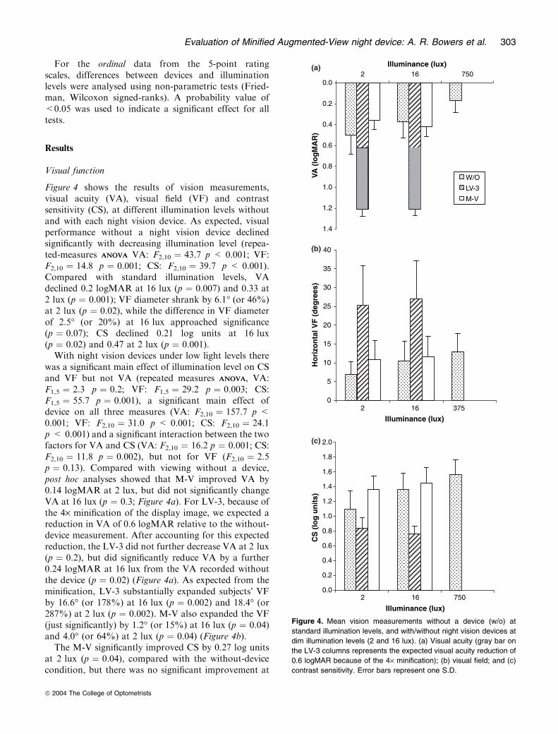
Figure 4 shows the results of vision measurements,visual acuity (VA), visual field (VF) and contrastsensitivity (CS), at different illumination levels withoutand with each night vision device. As expected, visualperformance without a night vision device declinedsignificantly with decreasing illumination level (repea-ted-measures ANOVAANOVA VA: F2,10 ¼ 43.7 p < 0.001; VF:F2,10 ¼ 14.8 p ¼ 0.001; CS: F2,10 ¼ 39.7 p < 0.001).Compared with standard illumination levels, VAdeclined 0.2 logMAR at 16 lux (p ¼ 0.007) and 0.33 at2 lux (p ¼ 0.001); VF diameter shrank by 6.1� (or 46%)at 2 lux (p ¼ 0.02), while the difference in VF diameterof 2.5� (or 20%) at 16 lux approached significance(p ¼ 0.07); CS declined 0.21 log units at 16 lux(p ¼ 0.02) and 0.47 at 2 lux (p ¼ 0.001).With night vision devices under low light levels there
was a significant main effect of illumination level on CSand VF but not VA (repeated measures ANOVAANOVA, VA:F1,5 ¼ 2.3 p ¼ 0.2; VF: F1,5 ¼ 29.2 p ¼ 0.003; CS:F1,5 ¼ 55.7 p ¼ 0.001), a significant main effect ofdevice on all three measures (VA: F2,10 ¼ 157.7 p <0.001; VF: F2,10 ¼ 31.0 p < 0.001; CS: F2,10 ¼ 24.1p < 0.001) and a significant interaction between the twofactors for VA and CS (VA: F2,10 ¼ 16.2 p ¼ 0.001; CS:F2,10 ¼ 11.8 p ¼ 0.002), but not for VF (F2,10 ¼ 2.5p ¼ 0.13). Compared with viewing without a device,post hoc analyses showed that M-V improved VA by0.14 logMAR at 2 lux, but did not significantly changeVA at 16 lux (p ¼ 0.3; Figure 4a). For LV-3, because ofthe 4· minification of the display image, we expected areduction in VA of 0.6 logMAR relative to the without-device measurement. After accounting for this expectedreduction, the LV-3 did not further decrease VA at 2 lux(p ¼ 0.2), but did significantly reduce VA by a further0.24 logMAR at 16 lux from the VA recorded withoutthe device (p ¼ 0.02) (Figure 4a). As expected from theminification, LV-3 substantially expanded subjects� VFby 16.6� (or 178%) at 16 lux (p ¼ 0.002) and 18.4� (or287%) at 2 lux (p ¼ 0.002). M-V also expanded the VF(just significantly) by 1.2� (or 15%) at 16 lux (p ¼ 0.04)and 4.0� (or 64%) at 2 lux (p ¼ 0.04) (Figure 4b).The M-V significantly improved CS by 0.27 log units
at 2 lux (p ¼ 0.04), compared with the without-devicecondition, but there was no significant improvement at
0.0
0.2
0.4
0.6
0.8
1.0
1.2
1.4
2 16 750Illuminance (lux)
2 16 375
VA (
log
MA
R)
W/O
LV-3
M-V
0
5
10
15
20
25
30
35
40
Illuminance (lux)
Ho
rizo
nta
l VF
(d
egre
es)
0.0
0.2
0.4
0.6
0.8
1.0
1.2
1.4
1.6
1.8
2.0
2 16 750
Illuminance (lux)
CS
(lo
g u
nit
s)
(a)
(b)
(c)
Figure 4. Mean vision measurements without a device (w/o) at
standard illumination levels, and with/without night vision devices at
dim illumination levels (2 and 16 lux). (a) Visual acuity (gray bar on
the LV-3 columns represents the expected visual acuity reduction of
0.6 logMAR because of the 4· minification); (b) visual field; and (c)
contrast sensitivity. Error bars represent one S.D.
Evaluation of Minified Augmented-View night device: A. R. Bowers et al. 303
ª 2004 The College of Optometrists
16 lux (p ¼ 0.21; Figure 4c). However the LV-3 signi-ficantly reduced CS by 0.6 log units (p ¼ 0.004) at16 lux (relative to without device), while the reductionof 0.27 log units at 2 lux approached significance(p ¼ 0.07). The CS measurements were taken at thesame distance without and with each device; thus thespatial frequencies of the letters on the Pelli–Robsonchart would be shifted towards higher frequencieswhen displayed as a minified image on the LV-3display. For four normal observers viewing without theLV-3, when viewing distance was increased from 1 to4 m, contrast sensitivity reduced by 0.1–0.15 log units.Therefore the reduction in CS with the LV-3 wasgreater than would be expected because of the mini-fication alone.
Indoor obstacle course
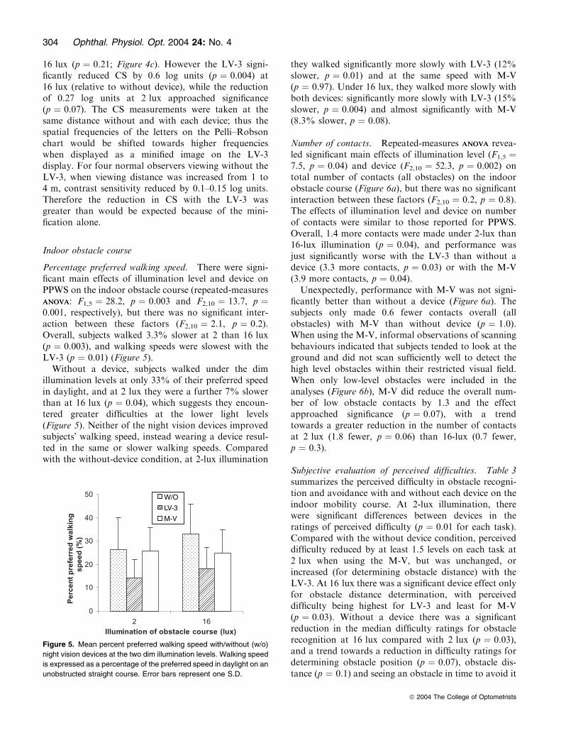
Percentage preferred walking speed. There were signi-ficant main effects of illumination level and device onPPWS on the indoor obstacle course (repeated-measuresANOVAANOVA: F1,5 ¼ 28.2, p ¼ 0.003 and F2,10 ¼ 13.7, p ¼0.001, respectively), but there was no significant inter-action between these factors (F2,10 ¼ 2.1, p ¼ 0.2).Overall, subjects walked 3.3% slower at 2 than 16 lux(p ¼ 0.003), and walking speeds were slowest with theLV-3 (p ¼ 0.01) (Figure 5).
Without a device, subjects walked under the dimillumination levels at only 33% of their preferred speedin daylight, and at 2 lux they were a further 7% slowerthan at 16 lux (p ¼ 0.04), which suggests they encoun-tered greater difficulties at the lower light levels(Figure 5). Neither of the night vision devices improvedsubjects� walking speed, instead wearing a device resul-ted in the same or slower walking speeds. Comparedwith the without-device condition, at 2-lux illumination
they walked significantly more slowly with LV-3 (12%slower, p ¼ 0.01) and at the same speed with M-V(p ¼ 0.97). Under 16 lux, they walked more slowly withboth devices: significantly more slowly with LV-3 (15%slower, p ¼ 0.004) and almost significantly with M-V(8.3% slower, p ¼ 0.08).
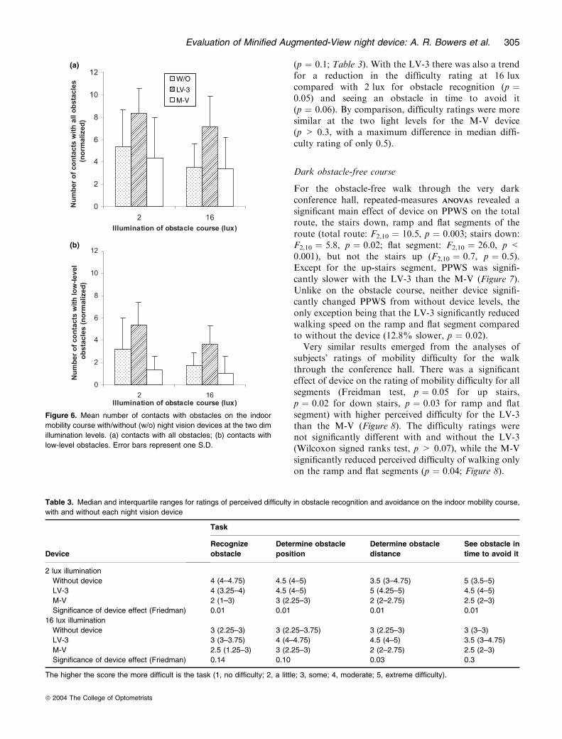
Number of contacts. Repeated-measures ANOVAANOVA revea-led significant main effects of illumination level (F1,5 ¼7.5, p ¼ 0.04) and device (F2,10 ¼ 52.3, p ¼ 0.002) ontotal number of contacts (all obstacles) on the indoorobstacle course (Figure 6a), but there was no significantinteraction between these factors (F2,10 ¼ 0.2, p ¼ 0.8).The effects of illumination level and device on numberof contacts were similar to those reported for PPWS.Overall, 1.4 more contacts were made under 2-lux than16-lux illumination (p ¼ 0.04), and performance wasjust significantly worse with the LV-3 than without adevice (3.3 more contacts, p ¼ 0.03) or with the M-V(3.9 more contacts, p ¼ 0.04).
Unexpectedly, performance with M-V was not signi-ficantly better than without a device (Figure 6a). Thesubjects only made 0.6 fewer contacts overall (allobstacles) with M-V than without device (p ¼ 1.0).When using the M-V, informal observations of scanningbehaviours indicated that subjects tended to look at theground and did not scan sufficiently well to detect thehigh level obstacles within their restricted visual field.When only low-level obstacles were included in theanalyses (Figure 6b), M-V did reduce the overall num-ber of low obstacle contacts by 1.3 and the effectapproached significance (p ¼ 0.07), with a trendtowards a greater reduction in the number of contactsat 2 lux (1.8 fewer, p ¼ 0.06) than 16-lux (0.7 fewer,p ¼ 0.3).
Subjective evaluation of perceived difficulties. Table 3summarizes the perceived difficulty in obstacle recogni-tion and avoidance with and without each device on theindoor mobility course. At 2-lux illumination, therewere significant differences between devices in theratings of perceived difficulty (p ¼ 0.01 for each task).Compared with the without device condition, perceiveddifficulty reduced by at least 1.5 levels on each task at2 lux when using the M-V, but was unchanged, orincreased (for determining obstacle distance) with theLV-3. At 16 lux there was a significant device effect onlyfor obstacle distance determination, with perceiveddifficulty being highest for LV-3 and least for M-V(p ¼ 0.03). Without a device there was a significantreduction in the median difficulty ratings for obstaclerecognition at 16 lux compared with 2 lux (p ¼ 0.03),and a trend towards a reduction in difficulty ratings fordetermining obstacle position (p ¼ 0.07), obstacle dis-tance (p ¼ 0.1) and seeing an obstacle in time to avoid it
W/O
LV-3
M-V
Figure 5. Mean percent preferred walking speed with/without (w/o)
night vision devices at the two dim illumination levels. Walking speed
is expressed as a percentage of the preferred speed in daylight on an
unobstructed straight course. Error bars represent one S.D.
304 Ophthal. Physiol. Opt. 2004 24: No. 4
ª 2004 The College of Optometrists
(p ¼ 0.1; Table 3). With the LV-3 there was also a trendfor a reduction in the difficulty rating at 16 luxcompared with 2 lux for obstacle recognition (p ¼0.05) and seeing an obstacle in time to avoid it(p ¼ 0.06). By comparison, difficulty ratings were moresimilar at the two light levels for the M-V device(p > 0.3, with a maximum difference in median diffi-culty rating of only 0.5).
Dark obstacle-free course
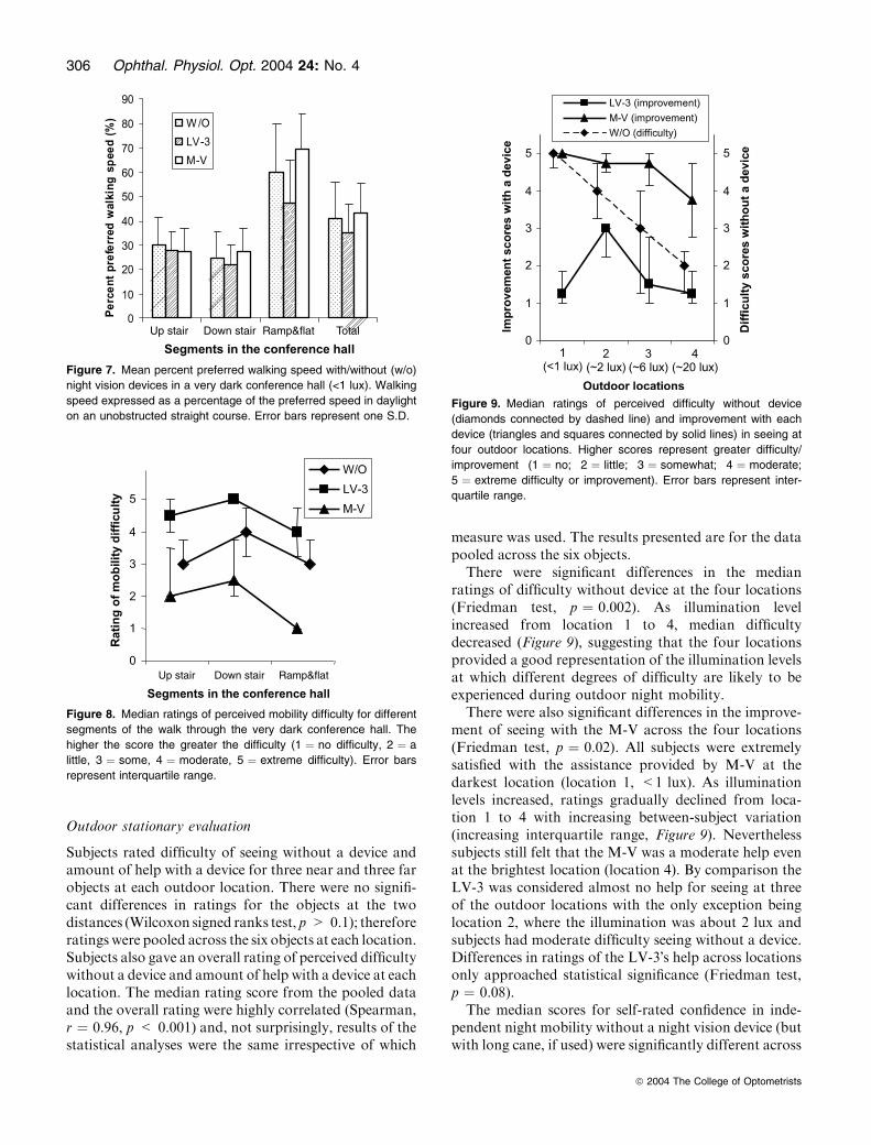
For the obstacle-free walk through the very darkconference hall, repeated-measures ANOVAANOVAs revealed asignificant main effect of device on PPWS on the totalroute, the stairs down, ramp and flat segments of theroute (total route: F2,10 ¼ 10.5, p ¼ 0.003; stairs down:F2,10 ¼ 5.8, p ¼ 0.02; flat segment: F2,10 ¼ 26.0, p <0.001), but not the stairs up (F2,10 ¼ 0.7, p ¼ 0.5).Except for the up-stairs segment, PPWS was signifi-cantly slower with the LV-3 than the M-V (Figure 7).Unlike on the obstacle course, neither device signifi-cantly changed PPWS from without device levels, theonly exception being that the LV-3 significantly reducedwalking speed on the ramp and flat segment comparedto without the device (12.8% slower, p ¼ 0.02).
Very similar results emerged from the analyses ofsubjects� ratings of mobility difficulty for the walkthrough the conference hall. There was a significanteffect of device on the rating of mobility difficulty for allsegments (Freidman test, p ¼ 0.05 for up stairs,p ¼ 0.02 for down stairs, p ¼ 0.03 for ramp and flatsegment) with higher perceived difficulty for the LV-3than the M-V (Figure 8). The difficulty ratings werenot significantly different with and without the LV-3(Wilcoxon signed ranks test, p > 0.07), while the M-Vsignificantly reduced perceived difficulty of walking onlyon the ramp and flat segments (p ¼ 0.04; Figure 8).
(a)
(b)
W/O
LV-3
M-V
Figure 6. Mean number of contacts with obstacles on the indoor
mobility course with/without (w/o) night vision devices at the two dim
illumination levels. (a) contacts with all obstacles; (b) contacts with
low-level obstacles. Error bars represent one S.D.
Table 3. Median and interquartile ranges for ratings of perceived difficulty in obstacle recognition and avoidance on the indoor mobility course,
with and without each night vision device
Device
Task
Recognize
obstacle
Determine obstacle
position
Determine obstacle
distance
See obstacle in
time to avoid it
2 lux illumination
Without device 4 (4–4.75) 4.5 (4–5) 3.5 (3–4.75) 5 (3.5–5)
LV-3 4 (3.25–4) 4.5 (4–5) 5 (4.25–5) 4.5 (4–5)
M-V 2 (1–3) 3 (2.25–3) 2 (2–2.75) 2.5 (2–3)
Significance of device effect (Friedman) 0.01 0.01 0.01 0.01
16 lux illumination
Without device 3 (2.25–3) 3 (2.25–3.75) 3 (2.25–3) 3 (3–3)
LV-3 3 (3–3.75) 4 (4–4.75) 4.5 (4–5) 3.5 (3–4.75)
M-V 2.5 (1.25–3) 3 (2.25–3) 2 (2–2.75) 2.5 (2–3)
Significance of device effect (Friedman) 0.14 0.10 0.03 0.3
The higher the score the more difficult is the task (1, no difficulty; 2, a little; 3, some; 4, moderate; 5, extreme difficulty).
Evaluation of Minified Augmented-View night device: A. R. Bowers et al. 305
ª 2004 The College of Optometrists
Outdoor stationary evaluation
Subjects rated difficulty of seeing without a device andamount of help with a device for three near and three farobjects at each outdoor location. There were no signifi-cant differences in ratings for the objects at the twodistances (Wilcoxon signed ranks test, p > 0.1); thereforeratings were pooled across the six objects at each location.Subjects also gave an overall rating of perceived difficultywithout a device and amount of help with a device at eachlocation. The median rating score from the pooled dataand the overall rating were highly correlated (Spearman,r ¼ 0.96, p < 0.001) and, not surprisingly, results of thestatistical analyses were the same irrespective of which
measure was used. The results presented are for the datapooled across the six objects.
There were significant differences in the medianratings of difficulty without device at the four locations(Friedman test, p ¼ 0.002). As illumination levelincreased from location 1 to 4, median difficultydecreased (Figure 9), suggesting that the four locationsprovided a good representation of the illumination levelsat which different degrees of difficulty are likely to beexperienced during outdoor night mobility.
There were also significant differences in the improve-ment of seeing with the M-V across the four locations(Friedman test, p ¼ 0.02). All subjects were extremelysatisfied with the assistance provided by M-V at thedarkest location (location 1, <1 lux). As illuminationlevels increased, ratings gradually declined from loca-tion 1 to 4 with increasing between-subject variation(increasing interquartile range, Figure 9). Neverthelesssubjects still felt that the M-V was a moderate help evenat the brightest location (location 4). By comparison theLV-3 was considered almost no help for seeing at threeof the outdoor locations with the only exception beinglocation 2, where the illumination was about 2 lux andsubjects had moderate difficulty seeing without a device.Differences in ratings of the LV-3�s help across locationsonly approached statistical significance (Friedman test,p ¼ 0.08).
The median scores for self-rated confidence in inde-pendent night mobility without a night vision device (butwith long cane, if used) were significantly different across
Up stair Down stair Ramp&flat Total
Figure 7. Mean percent preferred walking speed with/without (w/o)
night vision devices in a very dark conference hall (<1 lux). Walking
speed expressed as a percentage of the preferred speed in daylight
on an unobstructed straight course. Error bars represent one S.D.
Up stair Down stair Ramp&flat
Figure 8. Median ratings of perceived mobility difficulty for different
segments of the walk through the very dark conference hall. The
higher the score the greater the difficulty (1 ¼ no difficulty, 2 ¼ a
little, 3 ¼ some, 4 ¼ moderate, 5 ¼ extreme difficulty). Error bars
represent interquartile range.
Figure 9. Median ratings of perceived difficulty without device
(diamonds connected by dashed line) and improvement with each
device (triangles and squares connected by solid lines) in seeing at
four outdoor locations. Higher scores represent greater difficulty/
improvement (1 ¼ no; 2 ¼ little; 3 ¼ somewhat; 4 ¼ moderate;
5 ¼ extreme difficulty or improvement). Error bars represent inter-
quartile range.
306 Ophthal. Physiol. Opt. 2004 24: No. 4
ª 2004 The College of Optometrists
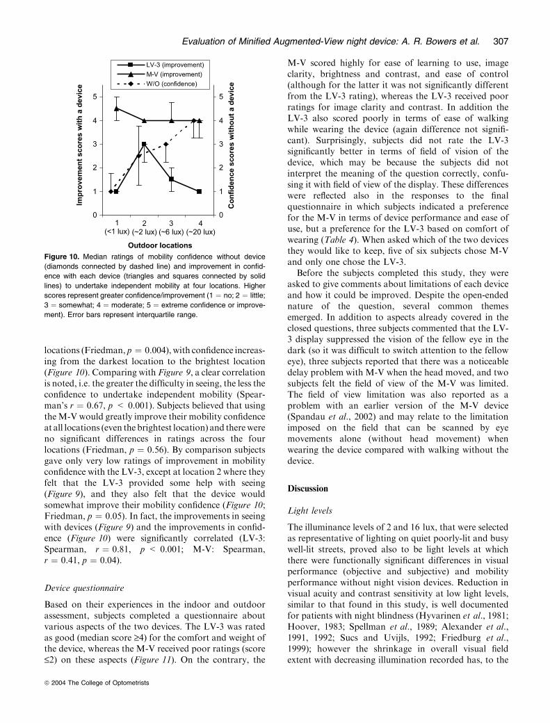
locations (Friedman, p ¼ 0.004), with confidence increas-ing from the darkest location to the brightest location(Figure 10). Comparing with Figure 9, a clear correlationis noted, i.e. the greater the difficulty in seeing, the less theconfidence to undertake independent mobility (Spear-man’s r ¼ 0.67, p < 0.001). Subjects believed that usingtheM-V would greatly improve their mobility confidenceat all locations (even thebrightest location) and therewereno significant differences in ratings across the fourlocations (Friedman, p ¼ 0.56). By comparison subjectsgave only very low ratings of improvement in mobilityconfidence with the LV-3, except at location 2 where theyfelt that the LV-3 provided some help with seeing(Figure 9), and they also felt that the device wouldsomewhat improve their mobility confidence (Figure 10;Friedman, p ¼ 0.05). In fact, the improvements in seeingwith devices (Figure 9) and the improvements in confid-ence (Figure 10) were significantly correlated (LV-3:Spearman, r ¼ 0.81, p < 0.001; M-V: Spearman,r ¼ 0.41, p ¼ 0.04).
Device questionnaire
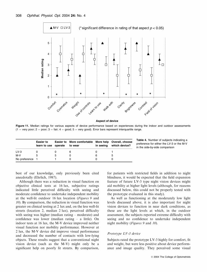
Based on their experiences in the indoor and outdoorassessment, subjects completed a questionnaire aboutvarious aspects of the two devices. The LV-3 was ratedas good (median score ‡4) for the comfort and weight ofthe device, whereas the M-V received poor ratings (score£2) on these aspects (Figure 11). On the contrary, the
M-V scored highly for ease of learning to use, imageclarity, brightness and contrast, and ease of control(although for the latter it was not significantly differentfrom the LV-3 rating), whereas the LV-3 received poorratings for image clarity and contrast. In addition theLV-3 also scored poorly in terms of ease of walkingwhile wearing the device (again difference not signifi-cant). Surprisingly, subjects did not rate the LV-3significantly better in terms of field of vision of thedevice, which may be because the subjects did notinterpret the meaning of the question correctly, confu-sing it with field of view of the display. These differenceswere reflected also in the responses to the finalquestionnaire in which subjects indicated a preferencefor the M-V in terms of device performance and ease ofuse, but a preference for the LV-3 based on comfort ofwearing (Table 4). When asked which of the two devicesthey would like to keep, five of six subjects chose M-Vand only one chose the LV-3.
Before the subjects completed this study, they wereasked to give comments about limitations of each deviceand how it could be improved. Despite the open-endednature of the question, several common themesemerged. In addition to aspects already covered in theclosed questions, three subjects commented that the LV-3 display suppressed the vision of the fellow eye in thedark (so it was difficult to switch attention to the felloweye), three subjects reported that there was a noticeabledelay problem with M-V when the head moved, and twosubjects felt the field of view of the M-V was limited.The field of view limitation was also reported as aproblem with an earlier version of the M-V device(Spandau et al., 2002) and may relate to the limitationimposed on the field that can be scanned by eyemovements alone (without head movement) whenwearing the device compared with walking without thedevice.
Discussion
Light levels
The illuminance levels of 2 and 16 lux, that were selectedas representative of lighting on quiet poorly-lit and busywell-lit streets, proved also to be light levels at whichthere were functionally significant differences in visualperformance (objective and subjective) and mobilityperformance without night vision devices. Reduction invisual acuity and contrast sensitivity at low light levels,similar to that found in this study, is well documentedfor patients with night blindness (Hyvarinen et al., 1981;Hoover, 1983; Spellman et al., 1989; Alexander et al.,1991, 1992; Sucs and Uvijls, 1992; Friedburg et al.,1999); however the shrinkage in overall visual fieldextent with decreasing illumination recorded has, to the
Figure 10. Median ratings of mobility confidence without device
(diamonds connected by dashed line) and improvement in confid-
ence with each device (triangles and squares connected by solid
lines) to undertake independent mobility at four locations. Higher
scores represent greater confidence/improvement (1 ¼ no; 2 ¼ little;
3 ¼ somewhat; 4 ¼ moderate; 5 ¼ extreme confidence or improve-
ment). Error bars represent interquartile range.
Evaluation of Minified Augmented-View night device: A. R. Bowers et al. 307
ª 2004 The College of Optometrists
best of our knowledge, only previously been citedanecdotally (Ehrlich, 1987).
Although there was a reduction in visual function onobjective clinical tests at 16 lux, subjective ratingsindicated little perceived difficulty with seeing andmoderate confidence to undertake independent mobilityat the well-lit outdoor 16 lux location (Figures 9 and10). By comparison, the reduction in visual function wasgreater on clinical testing at 2 lux and, on the less well-litstreets (location 2, median 2 lux), perceived difficultywith seeing was higher (median rating – moderate) andconfidence was lower (median rating – a little). Onindoor tests at 16 lux, the M-V device improved neithervisual function nor mobility performance. However at2 lux, the M-V device did improve visual performanceand decreased the number of contacts with low-lyingobjects. These results suggest that a conventional nightvision device (such as the M-V) might only be asignificant help on poorly lit streets. By comparison,
for patients with restricted fields in addition to nightblindness, it would be expected that the field expansionfeature of future LV-3 type night vision devices mightaid mobility at higher light levels (although, for reasonsdiscussed below, this could not be properly tested withthe prototype evaluated in this study).
As well as functioning at the moderately low lightlevels discussed above, it is also important for nightvision devices to function in near dark conditions, asthese are the light levels at which, in the outdoorassessment, the subjects reported extreme difficulty withseeing and no confidence to undertake independentnight mobility (Figures 9 and 10).
Prototype LV-3 device
Subjects rated the prototype LV-3 highly for comfort, fitand weight, but were less positive about device perform-ance and image quality. They perceived some visual
Table 4. Number of subjects indicating a
preference for either the LV-3 or the M-V
in the side-by-side comparison
Easier to
learn to use
Easier to
operate
More comfortable
to wear
More help
in seeing
Overall, choose
which device?
LV-3 0 0 6 0 1
M-V 5 5 0 6 5
No preference 1 1 0 0 0
Aspect of device
p < 0.05)
Figure 11. Median ratings for various aspects of device performance based on experiences during the indoor and outdoor assessments
(1 ¼ very poor; 2 ¼ poor; 3 ¼ fair; 4 ¼ good; 5 ¼ very good). Error bars represent interquartile range.
308 Ophthal. Physiol. Opt. 2004 24: No. 4
ª 2004 The College of Optometrists
benefit of the device outdoors at the location where thelighting was in the 2-lux range, but no benefit at thedarkest locationwhere the prototype camera did not haveenough sensitivity to capture an image, and no benefit atthe better-illuminated locations where device perform-ancewas unable tomatchnatural vision.Nevertheless onesubject indicated that he would choose the LV-3 ratherthan theM-Vdevice, as he liked the option of being able touse whatever natural vision he retained at the reducedlight levels (by looking through the display, moving hiseye out of the field of the display or switching attention tothe other eye), which was not possible with the M-V as itblocked the natural view. Furthermore, our outdoor illu-mination measurements indicated that there are manysituations in which outdoor lighting levels within a citycenter are likely to be sufficient for the patient’s naturalvision to be useful: 30% of illuminance measurementswere higher than 16 lux in downtown Boston. Underthese conditions, an occluding display such as the M-Vmay hinder patients� mobility.The LV-3 device expanded the visual field of all
subjects, but generally the expansion was less than thetheoretically predicted 4·. Visual acuity and contrastsensitivity with the device were reduced more thanwould be expected from the minification alone. Themain factors limiting visual performance and fieldexpansion with the LV-3 were: poor camera sensitivityat low light levels (<2 lux), insufficient range on thecontrast enhancement and limited resolution of both thecamera and the display. These aspects of deviceperformance are being addressed in the next stage ofdevelopment.Mobility performance on the indoor obstacle course
was very poor when wearing the LV-3 (slow walkingspeeds, high number of obstacle contacts and difficul-ties with determining object positions). Furthermore,on the obstacle-free walk along the flat section in thedark conference hall, walking speed was significantlyslower with the LV-3 than without. Apart from thecamera’s poor low-light sensitivity, which limiteddevice performance on some parts of the obstaclecourse (and on the entire conference hall walk), a bigfactor impacting mobility performance was the spatialdistortion of obstacle position resulting from theminification. Although subjects understood the conceptof the minification, had practiced reaching out toobjects seen on the minified display and had practicedwalking around obstacles in a dark room whilewearing the device before starting the indoor mobilitycourse, this training period may have been too brief tosufficiently habituate the user to the challenge of usinga minified image for obstacle avoidance.At the low light levels on the indoor course, subjects
found it very difficult to vision multiplex (alternateattention) between the gray-scale minified video image
and their natural vision. If they had been able tomultiplex, their natural view of the scene might havehelped with adaptation to the device and determiningthe true position of obstacles. The gray-scale imageaffected the entire visual field of our subjects: theycommented that the light emitted by the displayinterfered with dark adaptation and they were usuallyunable to swap their attention to use the low-lightnatural view from the other eye. Furthermore, the LV-3display was fitted in front of the dominant eye, whichmay also have contributed to difficulties in alternatingattention to the non-dominant eye. In daylight condi-tions one subject found it impossible to alternateattention to the fellow eye when the display wasmounted in front of the dominant eye, but had noproblems when it was in front of the non-dominant eye.The next generation of the prototype device will offerusers the option to use the edge-contour image, whichwill enable vision multiplexing by looking through thecontour view to the real world. We anticipate that it willbe easier to apply vision multiplexing with the edge-contour mode than with the gray-scale image mode asthe illuminated pixels of the contours occupy only asmall portion of the display area, rarely obscure anydetail of the real-world view for any length of time anddo not significantly affect the level of (dark) adaptationof the eye. The light adaptation and eye dominancedifficulties encountered with vision multiplexing bet-ween the two eyes when using the LV-3 should beeliminated by the use of the edge-contour image in thenext prototype.
Due to the minimal level of training and problemswith vision multiplexing with the gray-scale image, theresults of the LV-3 evaluation might have underestima-ted the full benefit of the novel field expansion featurethat is believed to be fundamental to the Minified-Contours Augmented-View concept (see Introduction)of the new night vision device (Peli, 2001; Vargas-Martin and Peli, 2002). More extensive training, as wellas full implementation of the edge-contour image tofacilitate vision multiplexing, may be necessary to usethe field expansion feature more effectively. If visionmultiplexing is easier, then the field-expansion featurecould be used in a more dynamic fashion enabling betterinterplay between the field-expanded view and thenatural view than with the gray-scale image (i.e.attention could be swapped rapidly and intermittentlyfrom the natural view to the minified, field-expandedview to gain advance warning about obstacles ororientation information from outside of the field ofvision). Preliminary testing within a virtual environmentindicates that subjects with restricted visual fields areable to successfully use the minified edge-contour imageto aid visual search for objects outside of the habitualvisual field, and that they quickly learn the relationship
Evaluation of Minified Augmented-View night device: A. R. Bowers et al. 309
ª 2004 The College of Optometrists
between the apparent position of an object on theminified display and its true position (Luo and Peli,2004). Furthermore, since carrying out the LV-3 eval-uation, we have demonstrated that inclusion of a centermark on the device display facilitates adaptation forpeople with a visual field extent less than that of thedisplay (Luo and Peli, 2004); this feature will beincorporated in the next generation prototype LV-4device. It is suggested that the field expansion aspect ofthe Minified-Contours Augmented-View concept meritsfurther investigation in a longer-term study of the LV-4device.
Multi-Vision (M-V) device
Subjects were very enthusiastic about the way the M-Vdevice made �night look like day� and gave highpositive ratings for device performance, but they didnot like the heavy weight and poor fit of the device.They also noticed that lack of colour information wasa problem at pedestrian crossings with signal lightswhere both the red (do not walk) and white (safe tocross) signals appeared white on the display and werenot distinguishable by shape. On the clinical tests ofvisual function used in this study, visual performanceimproved significantly with the M-V (compared towithout) at 2 lux, but not at 16 lux. Although theranges of contrast and brightness adjustments weresufficiently wide on the M-V, visual acuity wasrestricted by the limited resolutions of display andcamera. Low contrast letters on the Pelli–Robson chartmay have been washed out by the automatic exposurecontrol of the camera and the contrast enhancement ofthe control box. Nevertheless our findings suggest thatthe performance of the M-V device tested is superior tothat of an earlier version where visual acuity with thedevice was better than without only up to 0.01 cd m)2
(0.03 lux) and contrast sensitivity up to 0.1 cd m)2
(0.3 lux) (Friedburg et al., 1999); however visual per-formance at light levels above 0.1 cd m)2 was notevaluated in that study.
Subjective ratings of the potential of the M-V deviceto improve confidence to undertake independent mobil-ity were high for all outdoor locations and littleperceived difficulty was reported for obstacle detectionand avoidance on the indoor course. However thesehighly positive subjective ratings did not appear to bereflected in the modest improvement in mobility per-formance on the indoor course when using the device.The density of obstacles on the indoor course was muchhigher than would be experienced outdoors and subjectswere asked to walk the course without using their longcane. Therefore they were presented with an artificialsituation and had to utilize different mobility strategiesthan they normally would. Factors related to device
usage while mobile, such as problems with parallax(from the monocular camera view) and judging obstacledistance, system delay during head movement whichdegrades image quality, and the need to adjust habitualscanning patterns (make greater use of head move-ments) probably were not taken into account by thesubjects in the stationary outdoor ratings, but werenevertheless reported after the indoor mobility assess-ment. Instead it appears that subjects� ratings mighthave been influenced by their initial enthusiasm for theperceived improvement in vision with the device, whilemobility performance was limited by the lack ofexperience of using the device and course complexity.The mismatch between subjective and objective findingsreinforces the importance of training and adaptation inorder to fully evaluate the effects of a device on mobilityperformance. Mobility performance is likely to improvefollowing a period of training and use of the device inrealistic outdoor settings; however, with the exception ofone investigation (Hartong et al., 2004), those nightvision device studies that have included an outdoormobility assessment (Morrissette et al., 1983; Rohrschn-eider et al., 2000; Spandau et al., 2002) have notincluded a period of home-use of the device prior tothe evaluation.
For the walk through the dark conference hall, theM-V provided much better levels of visual function thansubjects could possibly achieve with their natural visionat the scotopic light levels. Perceived difficulty withmobility was significantly lower with than without thedevice on the ramp and flat sections, yet walking speedwas not significantly faster with the device. This suggeststhat for the ramp and flat segments, although the extravisual information provided by the M-V improvedconfidence to walk (which is important from the user’sperspective), it was not required for mobility. The rampand flat sections were relatively short and subjects knewthat they were obstacle-free, so having determined thedirection of travel, little visual information was neces-sary for mobility; thus walking speed with and withoutthe M-V was about 60% of the preferred walking speedin good lighting (Figure 7), as compared with <30% onthe indoor obstacle course where visual information wasessential to mobility (Figure 5). After sufficient trainingand adaptation to using a night vision device, the extentto which the device is likely to improve mobility willdepend on the visual requirements of the mobility taskas well as the extent to which non-visual information isused to aid mobility, such as tactile information fromuse of stair railings or long cane.
Conclusions
Although the results of this study were limited bysmall sample size and the lack of training and time for
310 Ophthal. Physiol. Opt. 2004 24: No. 4
ª 2004 The College of Optometrists
adaptation to the use of the night vision devices, theaims of the study are fulfilled in that the informationnecessary to direct future development of the nextprototype LV-4 is provided. Subjects� preference forthe better comfort, fit and lighter weight of the LV-3device in comparison to the M-V device confirms thatsome of the cosmetic and ergonomic disadvantages ofother currently available devices have been successfullyaddressed. The next stage of development will focuson improving camera sensitivity, and the imagequality and contrast. The Minified-Contours Augmen-ted-View concept will be fully implemented by inclu-ding the edge-contour image and will also use acustom-designed spectacle frame with a wider range offitting adjustments to provide an even better ergo-nomic design. With improved camera sensitivity andthe edge-contour image, patients should be able tomake better use of the field expansion and visionmultiplexing features to aid outdoor night mobilitythan was possible with the prototype LV-3. The nextprototype LV-4 will provide flexibility for patients touse their natural vision when light levels are sufficientand when they are not, the edge-contour or fullgray-scale image modes. Additionally they will havethe option of viewing a minified image or using digitalzoom to reduce the minification and display a 1:1image. A more extensive evaluation of the nextgeneration device is planned, which will include devicetraining, a period of home use of the device and amobility evaluation on an outdoor course at night.
Acknowledgements
Supported in part by NIH grants No. EY12912 and No.EY12890.MicroOptical Engineering Corp provided the proto-
type LV-3 device. Visys, Germany (now Trivisio,Switzerland) provided the Multi-Vision device.
Disclosures
Dr Rensing is an employee of MicroOptical EngineeringCorp., which has a financial interest in the LV-3technology. Dr Peli has a financial interest in themultiplexing technology through a patent and is aconsultant to MicroOptical. Dr Bowers and Dr Luohave no financial interests in the devices evaluated inthis study.
References
Alexander, K. R., Derlacki, D. J., Fishman, G. A. andPeachey, N. S. (1991) Acuity-luminance and foveal incre-
ment threshold functions in retinitis-pigmentosa. Invest.Ophthalmol. Vis. Sci. 32, 1446–1454.
Alexander, K. R., Derlacki, D. J. and Fishman, G. A. (1992)
Contrast thresholds for letter identification in retinitis-pigmentosa. Invest. Ophthalmol. Vis. Sci. 33, 1846–1852.
Berson, E. L., Mehaffey, L., III and Rabin, A. R. (1973a) A
night vision device as an aid for patients with retinitispigmentosa. Arch. Ophthalmol. 90, 112–116.
Berson, E. L., Rabin, A. R. and Mehaffey, L., III (1973b)
Advances in night vision technology. A pocketscope forpatients with retinitis pigmentosa. Arch. Ophthalmol. 90,
427–431.Berson, E. L., Mehaffey, L., III and Rabin, A. R. (1974) A
night vision pocketscope for patients with retinitis pig-mentosa. Design considerations. Arch. Ophthalmol. 91,
495–500.
Black, A., Lovie-Kitchin, J. E., Woods, R. L., Arnold, N.,Byrnes, J. and Murrish, J. (1996) Mobility performance withretinitis pigmentosa. Clin. Exp. Optom. 80, 1–12.
Clark-Carter, D. D., Heyes, A. D. and Howarth, C. I. (1986)The efficiency and walking speed of visually impairedpeople. Ergonomics 29, 779–789.
Ehrlich, D. A. (1987) A comparative study in the use of closed-
circuit television reading machines and optical aidsby patients with retinitis pigmentosa and maculopathy.Ophthal. Physiol. Opt. 7, 293–302.
Friedburg, C., Serey, L., Sharpe, L. T., Trauzettel-Klosinski,S. and Zrenner, E. (1999) Evaluation of the night visionspectacles on patients with impaired night vision. Graefes
Arch. Clin. Exp. Ophthalmol. 237, 125–136.Geruschat, D. R., Turano, K. A. and Stahl, J. W. (1998)Traditional measures of mobility performance and retinitis
pigmentosa. Optom. Vision Sci. 75, 525–537.Hartong, D. T., Jorritsma, F. F., Neve, J. J., Melis-Dankers,B. J. M. and Kooijman, A. C. (2004) Improved mobility andindependence of night-blind people using night-vision
goggles. Invest. Ophthalmol. Vis. Sci. 45, 1725–1731.Hassan, S. E., Lovie-Kitchin, J. E. and Woods, R. L. (2002)Vision and mobility performance of subjects with age-
related macular degeneration. Optom. Vision Sci. 79, 697–707.
Haymes, S., Guest, D., Heyes, A. and Johnston, A. (1994)
Comparison of functional mobility performance with clin-ical vision measures in simulated retinitis pigmentosa.Optom. Vision Sci. 71, 442–453.
Haymes, S., Guest, D., Heyes, A. and Johnston, A. (1996)
Mobility of people with retinitis pigmentosa as a function ofvision and psychological variables. Optom. Vision Sci. 73,621–637.
Hoover, K. L. (1983) Visual acuity with the ITT Night VisionAid for patients with night blindness. Am. J. Optom.Physiol. Opt. 60, 762–768.
Hyvarinen, L., Rovamo, J., Laurinen, P. and Peltomaa, A.(1981) Contrast sensitivity function in evaluation of visualimpairment due to retinitis pigmentosa. Acta Ophthalmol.
59, 763–773.Kanski, J. J. (2003) Clinical Ophthalmology, 5th edn. Butter-worth-Heinemann, Oxford.
Kuyk, T., Elliott, J. L. and Fuhr, P. S. (1998) Visual correlates
of mobility in real world settings in older adults with lowvision. Optom. Vision Sci. 75, 538–547.
Evaluation of Minified Augmented-View night device: A. R. Bowers et al. 311
ª 2004 The College of Optometrists
Lovie-Kitchin, J., Mainstone, J., Robinson, J. and Brown, B.
(1990) What areas of the visual field are important formobility in low vision patients? Clin. Vision Sci. 5, 249–263.
Luo, G. and Peli, E. (2004) Kinematics of visual search bytunnel vision patients with augmented vision see-throughHMD. SID 2004, Digest of Technical Papers, Society for
Information Display, 35, 1578–1581.Morrissette, D. L., Marmor, M. F. and Goodrich, G. L. (1983)An evaluation of night vision mobility aids. Ophthalmol. 90,1226–1230.
Peli, E. (2001) Vision multiplexing – an engineering approachto vision rehabilitation device development. Optom. VisionSci. 78, 304–315.
Pelli, D. G. (1986) The visual requirements of mobility. In:Low Vision. Principles and Applications (ed. G. C. Woo),Springer-Verlag, New York, pp. 134–146.
Pierrottet, C. O., Savaresi, G., Romano, S., Sportelli, V. andOrzalesi, N. (2003) Evaluation of the 3 MAX device fornight vision in retinitis pigmentosa patients. Invest. Oph-thalmol. Vis. Sci. 44, Abstract 1281.
Rohrschneider, K., Spandau, U., Wechsler, S. and Blankena-gel, A. (2000) Utilization of a new night vision enhancementdevice (DAVIS). Klinische Monatsblat. Augenheilkunde 217,
88–93.Soong, G., Lovie-Kitchin, J. E. and Brown, B. (2000)Preferred walking speed for assessment of mobility
performance: sighted guide vs non-sighted guide techniques.
Clin. Exp. Optom. 83, 279–282.Soong, G. P., Lovie-Kitchin, J. E. and Brown, B. (2001) Does
mobility performance of visually impaired adults improve
immediately after orientation and mobility training? Optom.Vision Sci. 78, 657–666.
Spandau, U. H., Wechsler, S. and Blankenagel, A. (2002)
Testing night vision goggles in a dark outside environment.Optom. Vision. Sci. 79, 39–45.
Spellman, D. C., Alexander, K. R., Fishman, G. A. andDerlacki,D. J. (1989)Letter contrast sensitivity in retinitis pig-
mentosa patients assessed byRegan charts.Retina 9, 287–291.Spitzer, M. B., Aquilino, P. D., McClelland, R. W., Olson, M.
H., Rensing, N. M., DiMarzio, C. A., Zavracky, P. M.,
Lemoncelli, A. and Hilliar, J. (1998) Optical approaches toincorporation of displays within glasses. J. Soc. InformationDisplay 6, 211–212.
Sucs, F. E. and Uvijls, A. (1992) Contrast sensitivity inretinitis-pigmentosa at different luminance levels. Clin.Vision Sci. 7, 147–151.
Turano, K. A., Geruschat, D. R., Stahl, J. W. and Massof, R.
W. (1999) Perceived visual ability for independent mobilityin persons with retinitis pigmentosa. Invest. Ophthalmol. Vis.Sci. 40, 865–877.
Vargas-Martin, F. and Peli, E. (2002) Augmented view forrestricted visual field: multiple device implementations.Optom. Vision Sci. 79, 715–723.
312 Ophthal. Physiol. Opt. 2004 24: No. 4
ª 2004 The College of Optometrists