Embed Size (px)
Citation preview
1
Rev. 0.1
BeRex ●website: www.berex.com ●email: [email protected]
Specifications and information are subject to change and products may be discontinued without notice. BeRex is a trademark of BeRex.
All other trademarks are the property of their respective owners. © 2012 BeRex
Pre
limin
ary
Man
ual
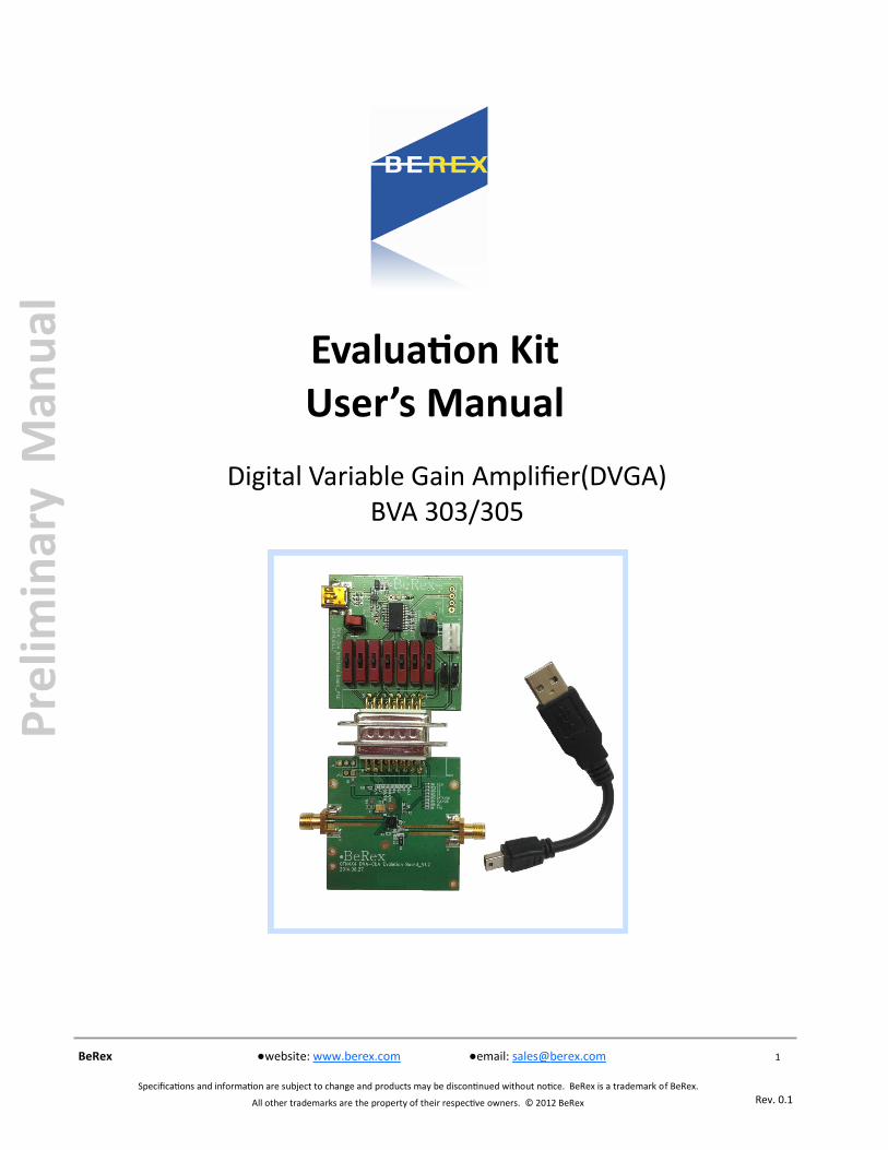
Evaluation Kit User’s Manual
Digital Variable Gain Amplifier(DVGA) BVA 303/305

2
Rev. 0.1
BeRex ●website: www.berex.com ●email: [email protected]
Specifications and information are subject to change and products may be discontinued without notice. BeRex is a trademark of BeRex.
All other trademarks are the property of their respective owners. © 2012 BeRex
Pre
limin
ary
Man
ual
Evaluation Kit User’s manual
BVA303/305
Table of contents
Introduction ……………………………..………………………………………………….…………….….. 3
Applications Support ………………………………………………………………………….….……. 3
Evaluation Kit Contents and Requirements …………………………………….……… 3
Kit Contents …………………………………………….………………………………………………...…. 3
Software Requirements …………………………………………………………………………….……… 3
Hardware Requirements………………………………………………………………………...………… 4
MCM BVA303/305 Evaluation Board Assembly …………..……………………..… 5
Overview ………………………………………………………………………………………………...…… 5
Outline showing functional overview...…………………………………………………………...…… 6
Hardware Operation …………………………………………………………………….……………... 7
USB Interface Board ………………………………………………………………….……………….... 9
USB Interface Board Overview ……………………………………………………………………………. 9
Connection of the USB Interface Board to the Evaluation Board …………………………..……… 9
USB Driver Installation ………………………………………………………….………………………….. 9
EVK Software Installation ………………………………………………………….……………..… 10
Using the Application Software Graphical User Interface ………….…….... 13
Evaluation Board Overview….…………………………………………………….……………….. 16
Technical Resources …..………………………………………………………………………………... 17
3
Rev. 0.1
BeRex ●website: www.berex.com ●email: [email protected]
Specifications and information are subject to change and products may be discontinued without notice. BeRex is a trademark of BeRex.
All other trademarks are the property of their respective owners. © 2012 BeRex
Pre
limin
ary
Man
ual
Evaluation Kit User’s manual
BVA303/305
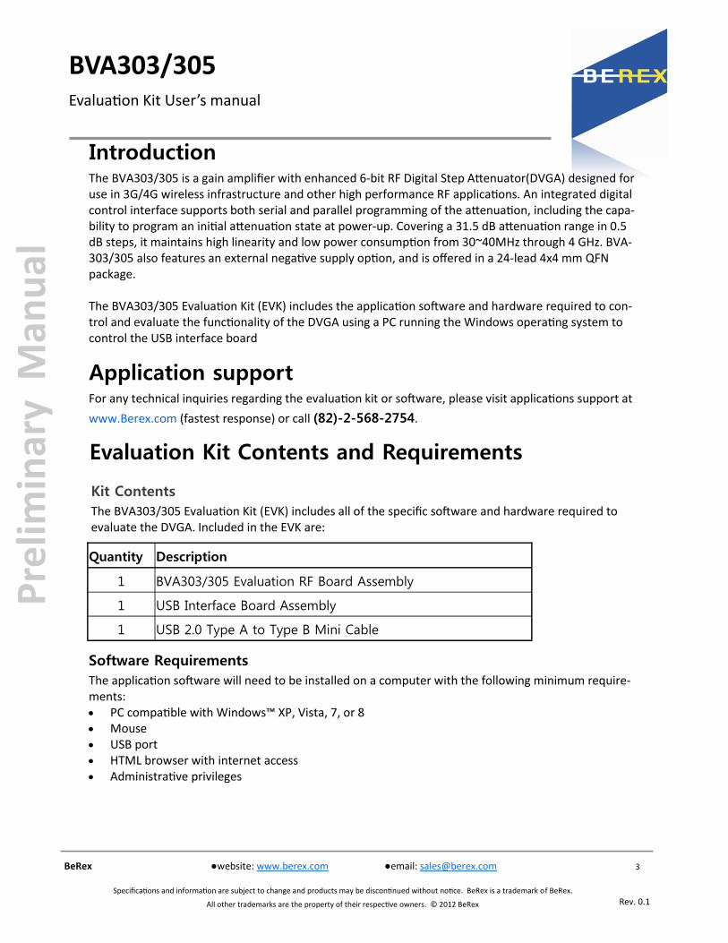
Introduction
The BVA303/305 is a gain amplifier with enhanced 6-bit RF Digital Step Attenuator(DVGA) designed for use in 3G/4G wireless infrastructure and other high performance RF applications. An integrated digital control interface supports both serial and parallel programming of the attenuation, including the capa-bility to program an initial attenuation state at power-up. Covering a 31.5 dB attenuation range in 0.5 dB steps, it maintains high linearity and low power consumption from 30~40MHz through 4 GHz. BVA-303/305 also features an external negative supply option, and is offered in a 24-lead 4x4 mm QFN package. The BVA303/305 Evaluation Kit (EVK) includes the application software and hardware required to con-trol and evaluate the functionality of the DVGA using a PC running the Windows operating system to control the USB interface board
Application support
For any technical inquiries regarding the evaluation kit or software, please visit applications support at
www.Berex.com (fastest response) or call (82)-2-568-2754.
Evaluation Kit Contents and Requirements
Kit Contents
The BVA303/305 Evaluation Kit (EVK) includes all of the specific software and hardware required to evaluate the DVGA. Included in the EVK are:
Quantity Description
1 BVA303/305 Evaluation RF Board Assembly
1 USB Interface Board Assembly
1 USB 2.0 Type A to Type B Mini Cable
Software Requirements
The application software will need to be installed on a computer with the following minimum require-ments: PC compatible with Windows™ XP, Vista, 7, or 8 Mouse USB port HTML browser with internet access Administrative privileges
4
Rev. 0.1
BeRex ●website: www.berex.com ●email: [email protected]
Specifications and information are subject to change and products may be discontinued without notice. BeRex is a trademark of BeRex.
All other trademarks are the property of their respective owners. © 2012 BeRex
Pre
limin
ary
Man
ual
Evaluation Kit User’s manual
BVA303/305
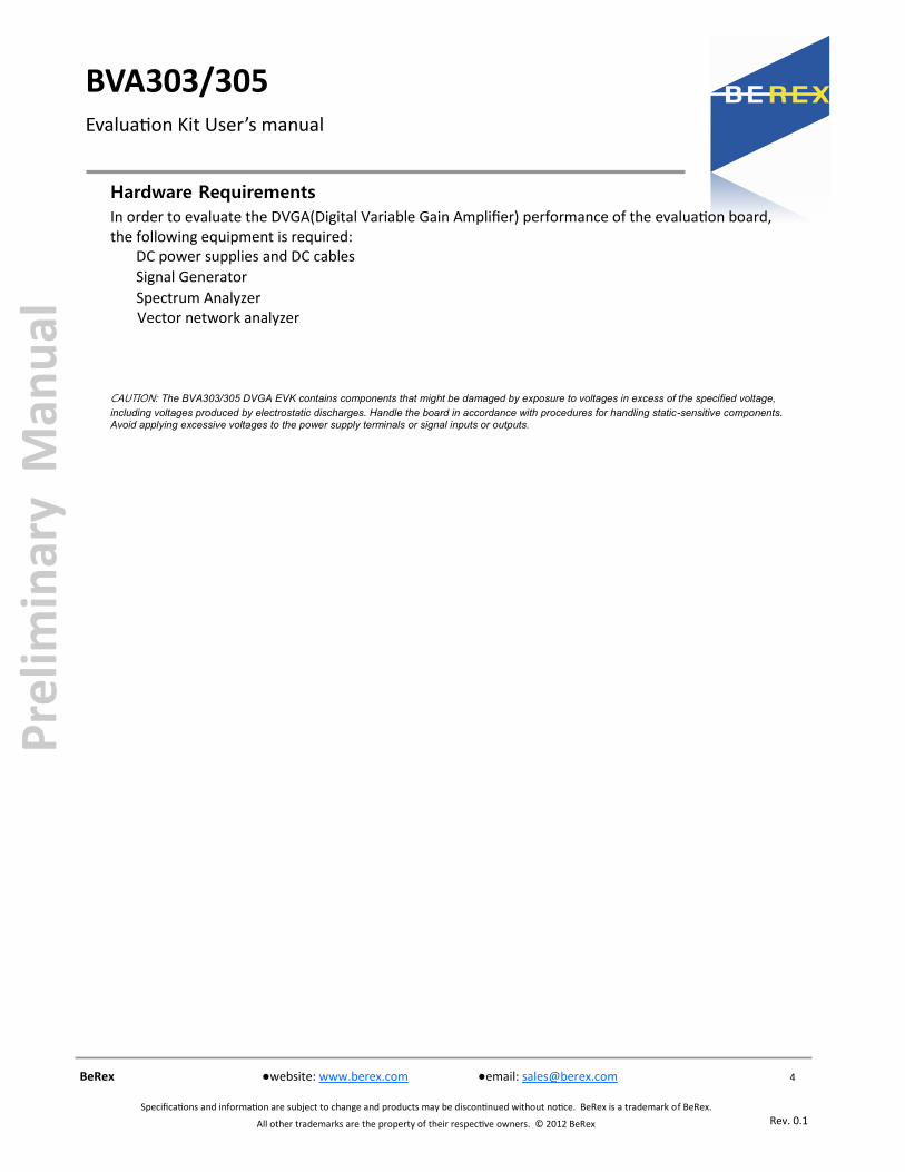
Hardware Requirements
In order to evaluate the DVGA(Digital Variable Gain Amplifier) performance of the evaluation board, the following equipment is required:
DC power supplies and DC cables
Signal Generator
Spectrum Analyzer Vector network analyzer
CAUTION: The BVA303/305 DVGA EVK contains components that might be damaged by exposure to voltages in excess of the specified voltage,
including voltages produced by electrostatic discharges. Handle the board in accordance with procedures for handling static-sensitive components. Avoid applying excessive voltages to the power supply terminals or signal inputs or outputs.

5
Rev. 0.1
BeRex ●website: www.berex.com ●email: [email protected]
Specifications and information are subject to change and products may be discontinued without notice. BeRex is a trademark of BeRex.
All other trademarks are the property of their respective owners. © 2012 BeRex
Pre
limin
ary
Man
ual
Evaluation Kit User’s manual
BVA303/305
MCM BVA303/305 Evaluation Board Assembly
Overview
The Evaluation Board is assembled with a BVA303/305 DVGA, SP2T mechanical switch (P/S), Parallel Programming switches (D1~D6,LE), several headers, and SMA connectors. The P/S switch is used for Parallel or Serial mode selection. The D1~D6,LE switches are used for setting the control bits in Direct Parallel programming mode.
Figure 1. MCM BVA303/305 Evaluation Board Assembly

6
Rev. 0.1
BeRex ●website: www.berex.com ●email: [email protected]
Specifications and information are subject to change and products may be discontinued without notice. BeRex is a trademark of BeRex.
All other trademarks are the property of their respective owners. © 2012 BeRex
Pre
limin
ary
Man
ual
Evaluation Kit User’s manual
BVA303/305
Figure 2. MCM BVA303/305 Evaluation Board Outline Showing Functional Overview
“High” in Direct Parallel Mode
Set for Latched Parallel/Serial Mode
“Low” in Direct Parallel Mode
Mini USB Connector port
Power supply Connector
Power-up Selector Jumper
VDD and VDD_DIG Jumper
Together
VSS Jumper to GND
Parallel/Serial Mode Selection
RF In(DSA Input)
RF out(Amp output)
Programming Switches(D1~D6, LE)
Set for PUP “High”
Set for PUP “Low”
1.2.3.4.
1. VDD (DSA+AMP VDD)2. VDD_DIG (INTERFACE BOARD VDD)3. GND4. GND

7
Rev. 0.1
BeRex ●website: www.berex.com ●email: [email protected]
Specifications and information are subject to change and products may be discontinued without notice. BeRex is a trademark of BeRex.
All other trademarks are the property of their respective owners. © 2012 BeRex
Pre
limin
ary
Man
ual
Evaluation Kit User’s manual
BVA303/305
Hardware Operation
1. Verify that all DC power supplies are turned off before proceeding
2. Connect the jumper on JP1, JP2
3. Position the P/S switch to Parallel or Serial mode
4. Set jumpers of PUP1 (J7) and PUP2 (J8) to be “HIGH” at upper position and “LOW” at down position
5. Set the D1~D6 and LE mechanical programming switches on board to support Direct Parallel, Latched Parallel, or Serial mode
a. Place D1~D6 and LE at the middle position to support Latched Parallel and Serial modes with
GUI application software and proper position of P/S switch
b. In Direct Parallel mode, D1~D6 can be set to “HIGH” or “LOW” to manually program the attenuation state while LE is
connected to “HIGH” without using the Mini USB Interface and GUI application software
Table 1. SP3T Switch Descriptions
6. Provide external power supply to the J4 connector (refer to the Operating Ranges table in the datasheet for the voltage range)
a. VDD is the positive power supply with 3.0V typical
b. VDD_DIG is the positive power supply for control signals with 1.8V typical, and it can be connected to VDD with jumper
on JP1 to simplify the test set-up
c. VSS is the external negative power supply with –3.3V typical. To simplify the test set-up, it can also be shorted to GND with
jumper on JP2 to enable using the internal negative voltage generator
Remark : In order to evaluate the DVGA of the evaluation board on parallel or serial mode, You should
connect the USB cable to a PC. And then to supply an External power VDD or VDD_DIG to the evalua-
tion board.
D1 0.5dB
D2 1dB
D3 2dB
D4 4dB
D5 8dB
D6 16dB
LE Latch enable

8
Rev. 0.1
BeRex ●website: www.berex.com ●email: [email protected]
Specifications and information are subject to change and products may be discontinued without notice. BeRex is a trademark of BeRex.
All other trademarks are the property of their respective owners. © 2012 BeRex
Pre
limin
ary
Man
ual
Evaluation Kit User’s manual
BVA303/305
HOW to set the PUP 1. Position the Parallel/Serial switch to Parallel mode
2. Set the “LE” Switch to “Low”
3. Set jumpers of PUP1 (J7) and PUP2 (J8) to be “HIGH” at upper position and “LOW” at down position as you need
(refer to Table 2)
Table 2. Parallel PUP Truth Table
4. Provide external power supply(3.0V)
P/S LE PUP2 PUP1 Attenuation state
0 0 0 0 Reference Loss
0 0 1 0 8 dB
0 0 0 1 16 dB
0 0 1 1 31.5 dB
0 1 X X Defined by C0.5-C16

9
Rev. 0.1
BeRex ●website: www.berex.com ●email: [email protected]
Specifications and information are subject to change and products may be discontinued without notice. BeRex is a trademark of BeRex.
All other trademarks are the property of their respective owners. © 2012 BeRex
Pre
limin
ary
Man
ual
Evaluation Kit User’s manual
BVA303/305
USB Interface Board Overview
A USB interface board (Figure 3) is included in
the Evaluation Kit. This board allows the user to send SPI commands to the device under test by using a PC running the Windows™ operating system. To install the software, extract the zip file to a temporary directory and follow the installation procedure included.
USB Interface Board
Connection of the USB Interface
Board to the Evaluation Board The Evaluation Board and the USB interface board contain the 15 pin D-sub connector. This feature allows the USB interface board (socket) to connect directly to the Evaluation Board (pin) on the front-side as shown in Figure 4.
Figure 3. USB interface board
Figure 4. DVGA USB Interface Board
Connected to the BVA303/305 Evaluation
Board for Latched Parallel and Serial
Programming
USB Driver Installation The latest USB interface board drivers are available via Microsoft Windows update. Internet connectivity is required to download the drivers. Connect the USB interface board to the PC and select the Windows Update option to obtain and install the drivers. If the USB board drivers are not installed, it will not be possible to run the program correctly.
A USB interface board (Figure 5) is included in the
Evaluation Kit. This software is available directly from FTDI’s website at http://www.ftdichip.com/Drivers/VCP.htm
Figure 5. USB Driver Installation

10
Rev. 0.1
BeRex ●website: www.berex.com ●email: [email protected]
Specifications and information are subject to change and products may be discontinued without notice. BeRex is a trademark of BeRex.
All other trademarks are the property of their respective owners. © 2012 BeRex
Pre
limin
ary
Man
ual
Evaluation Kit User’s manual
BVA303/305
EVK Software Installation
To install the DVGA evaluation software, unzip the
archive and execute the “setup.exe.”
Figures 6(a-c). Application Software
Installation Procedure
In order to evaluate the BVA303/305 performance, the Application Software has to be installed on your
computer.
The USB interface and DVGA application software is compatible with computers running Windows™ XP,
Vista, 7, or 8. This software is available directly from Berex’s website at
http://www.berex.com/Products/Documents/Installers/DVGA%20Evaluation%20Software%
20Installer%20R2.3.1.zip
After the setup.exe file has been executed, a
welcome screen will appear. It is strongly
recommended that all programs be closed prior to
running the install program. Click the “Next>”
button to proceed

11
Rev. 0.1
BeRex ●website: www.berex.com ●email: [email protected]
Specifications and information are subject to change and products may be discontinued without notice. BeRex is a trademark of BeRex.
All other trademarks are the property of their respective owners. © 2012 BeRex
Pre
limin
ary
Man
ual
Evaluation Kit User’s manual
BVA303/305
For most users the default install location for the
program files is sufficient. If a different location is
desired, the install program can be directed to
place the program files in an alternate location.
The software is installed for “Everyone” by
default. Once the desired location is selected
click “Next >.”
Figures 7(d-f). Application Software
Installation Procedure
As the software files are installed, a progress
indicator will be displayed. On slower computers,
installation of the software may proceed for a
few moments.
The Confirm Installation is ready to install the
DVGA evaluation software on your computer, then
click “Next>” to proceed with the software
installation.

12
Rev. 0.1
BeRex ●website: www.berex.com ●email: [email protected]
Specifications and information are subject to change and products may be discontinued without notice. BeRex is a trademark of BeRex.
All other trademarks are the property of their respective owners. © 2012 BeRex
Pre
limin
ary
Man
ual
Evaluation Kit User’s manual
BVA303/305
Once the evaluation software is installed, click
“Close” to exit.
A new Start Menu item under Peregrine
Semiconductor will appear in the start menu of
your computer. Select “DVGA Evaluation
Software” to launch the GUI.
Figures 8(g). Application Software
Installation Procedure

13
Rev. 0.1
BeRex ●website: www.berex.com ●email: [email protected]
Specifications and information are subject to change and products may be discontinued without notice. BeRex is a trademark of BeRex.
All other trademarks are the property of their respective owners. © 2012 BeRex
Pre
limin
ary
Man
ual
Evaluation Kit User’s manual
BVA303/305
Figure 9 displays the DVGA application software graphical user interface (GUI), which has the USB in-
terface board plugged into the computer. If the USB interface board is not connected when the appli-
cation software is launched, the message “No interface board connected! Please connect USB
-SPI Interface #101-0695.” will appear at the bottom of the screen.
In the upper left corner, under the Peregrine Logo there is a drop down menu item to select the part
for evaluation and the part description is right below the part number box.
Using the Application Software Graphical User Interface
Figure 9. DVGA Application Software Graphical User Interface (GUI)

14
Rev. 0.1
BeRex ●website: www.berex.com ●email: [email protected]
Specifications and information are subject to change and products may be discontinued without notice. BeRex is a trademark of BeRex.
All other trademarks are the property of their respective owners. © 2012 BeRex
Pre
limin
ary
Man
ual
Evaluation Kit User’s manual
BVA303/305
The DVGA application software GUI supports Latched Parallel and Serial modes, and shows the control
bit waveform at the right side of the GUI when the mode is selected.
The Send button changes functionality based on the control interface mode. Send Latch in Latched Par-
allel mode and Send Signal in Serial mode is provided to resend the programming bits to the device at
the same attenuation state.
Figure 10. Latched Parallel or Serial Mode
Continuous Pattern Loop can be selected to automatically step through each of the attenuation states.
The Attenuation Value box displays the attenuation value the DVGA is currently programmed. The user
can enter the desired attenuation value followed by the “Enter” key to program the DVGA.

15
Rev. 0.1
BeRex ●website: www.berex.com ●email: [email protected]
Specifications and information are subject to change and products may be discontinued without notice. BeRex is a trademark of BeRex.
All other trademarks are the property of their respective owners. © 2012 BeRex
Pre
limin
ary
Man
ual
Evaluation Kit User’s manual
BVA303/305
The center of the GUI is the attenuation slide bar that allows the user to quickly select the desired
attenuation. The arrows at the top and bottom can be clicked to increase or decrease attenuation state
at the minimum step size.

16
Rev. 0.1
BeRex ●website: www.berex.com ●email: [email protected]
Specifications and information are subject to change and products may be discontinued without notice. BeRex is a trademark of BeRex.
All other trademarks are the property of their respective owners. © 2012 BeRex
Pre
limin
ary
Man
ual
Evaluation Kit User’s manual
BVA303/305
Figure 11. BVA303/305 Evaluation Board Schematic
Evaluation Board Overview

17
Rev. 0.1
BeRex ●website: www.berex.com ●email: [email protected]
Specifications and information are subject to change and products may be discontinued without notice. BeRex is a trademark of BeRex.
All other trademarks are the property of their respective owners. © 2012 BeRex
Pre
limin
ary
Man
ual
Evaluation Kit User’s manual
BVA303/305
Additional technical resources are available for download in the Products section at www.berex.com. These include the Product Specification datasheet, Evaluation Kit schematic and Bill of Materials, Mate-rial Declaration form, and PC-compatible software file. Trademarks are subject to trademark claims.
Technical Resources