Embed Size (px)
Citation preview
___
1 - I
I I I I I
SUMMARY REPORT
on
I I I I I I I I 1 I 1 I I I I I I
EVALUATION CAPABILITIES FOR TRANSIENT PRESSURE TRANSDUCERS
t o
NATIONAL AERONAUTICS AND SPACE ADMINISTRATION OFFICE OF ADVANCED RESEARCH AND TECHNOLOGY
WASHINGTON, D . C .
February 15, 1966
by
John M. Allen
C o n t r a c t No . NASr- lOO(06)
BATTELLE MEMORIAL INSTITUTE C o l u m b u s L a b o r a t o r i e s
505 King A v e n u e C o l u m b u s , Ohio 43201
https://ntrs.nasa.gov/search.jsp?R=19660010845 2018-08-09T14:28:17+00:00Z
ACKNOWLEDGMENT
This program of es tab l i sh ing a t ransducer eva lua t ion c a p a b i l i t y a t
B a t t e l l e Memorial I n s t i t u t e w a s i n i t i a t e d under the monitorship of M r . Henry
Burlage of t he NASA Off ice of Advanced Research and Technology.
midpoint i n the program, M r . Burlage was succeeded by M r . Jack Suddreth, and
under h i s guidance, Dr. Marshall Burrows of the L e w i s Research Center w a s
appointed technica l monitor of t he program.
these t h r e e have been g r e a t l y appreciated.
A t roughly
The cooperat ion and guidance of
During the course of t h e program severa l B a t t e l l e profess iona l s t a f f
members have taken p a r t , including R. E . Robinson, J . L. Harp, K. 0. S te in ,
R. E. Mesloh, and Dr. C. Y . Liu. The background, s k i l l s , and cont r ibu t ions of
each are g r a t e f u l l y acknowledged.
Page
INTRODUCTION AND BACKGROUND . . . . . . . . . . . . . . . . . . . . . . . 1
TRANSDUCER EVALUATION SKILLS. . . . . . . . . . . . . . . . . . . . . . . 2
TRANSDUCER EVALUATION FACILITIES AVAILABLE. . . . . . . . . . . . . . . . 2
S t a t i c Pressure Calibration. . . . . . . . . . . . . . . . . . . . . 4 Coolant Flow Calibration . . . . . . . . . . . . . . . . . . . . . . 4 Sinusoidal Pressure Generator. . . . . . . . . . . . . . . . . . . . 6
S h o c k T u b e . . . . . . . . . . . . . . . . . . . . . . . . . . . . . 6
Other F a c i l i t i e s Available . . . . . . . . . . . . . . . . . . . . . 8
IMPROVEMENTS NEEDED IN EVALUATION CAPABILITIES. . . . . . . . . . . . . . 12
Externally A p p l i e d Vibrations. . . . . . . . . . . . . . . . . . . . 12
Osci l lat ing Pressure Generators. . . . . . . . . . . . . . . . . . . 13
Extended Steady-State Heat F l u x . . . . . . . . . . . . . . . . . . . 13
Osci l lat ing Rocket F a c i l i t y . . . . . . . . . . . . . . . . . . . . . 14
S u M . M A R Y . . . . . . . . . . . . . . . . . . . . . . . . . . . . . . . . . 15
L I S T OF FIGURES
Page
FIGURE I. TRANSDUCER EVALUATION LABORATORY . . . . . . . . . . . . . 3
FIGURE 11. STATIC PRESSURE AND COOLANT FLOW CALIBRATION BENCH . . . . 5
FIGURE 111. SINUSOIDAL PRESSURE GENERATOR. . . . . . . . . . . . . . . 7
FIGURE IV. SHOCK TUBE . . . . . . . . . . . . . . . . . . . . . . . 9
FIGURE V . HIGH HEAT-FLUX EXPOSURE ASSEMBLY ON ROCKET MOTOR . . . . . 11

EVALUATION CAPABILITIES FOR TRANSIENT PRESSURE TRANSDUCERS
John M. Allen B a t t e l l e Memorial I n s t i t u t e
Battelle has recent ly conducted a program f o r NASA aimed a t making
a v a i l a b l e t o t h e s c i e n t i f i c community t h e transducer eva lua t ion f a c i l i t i e s and
techniques developed over the past severa l years by Pr ince ton Universi ty under
NASA sponsorship. It i s of p a r t i c u l a r concern t o NASA tha t these s k i l l s and
labora tory c a p a b i l i t i e s be used e f f e c t i v e l y i n the various research and develop-
ment programs under Government sponsorship.
The Pr ince ton work i s w e l l sumnarized i n a recent paper by
J. P. Layton, et al,") which descr ibes both the test equipment used and some
of t h e r e s u l t s of recent t ransducer evaluat ions.
The Pr ince ton equipment has now been moved t o B a t t e l l e and placed i n
a s p e c i a l l abora tory with o ther instrumentation usefu l f o r p re s su re measurement
i n rocket combustion chambers. Although measurements of t h i s type a r e of
p a r t i c u l a r i n t e r e s t t o NASA, t h e s k i l l s t h a t have been developed, a s w e l l as
t h e laboratory f a c i l i t i e s , a r e appl icable t o many t ransducers developed f o r
o ther app l i ca t ions where dynamic pressures of appreciable a m p l i t u d e must be
measured.
The demands imposed on pressure t ransducers are becoming con t inua l ly
more s t r ingen t . This i s p a r t i c u l a r l y t r u e i n the measurement of combustion
pressures i n rocket motors during severe pressure t r a n s i e n t s such as those
(1) Jones, H. B., Jr., R. C. Knauer, J . P . Layton, and J . P . Thomas, "Transient Pressure Measurements i n Liquid Propel lan t Rocket Thrust Chambers", Instrument Society of America Transactions, Vol. 4, No. 2, pp 116-132 ( A p r i l 1965).
-2-
encountered i n s t a r tup , uns tab le burning, and shutdown. Accurate observat ion
and a n a l y s i s of these combustion pressure t r a n s i e n t s requires:
0 That t h e pressure transducers withstand t h e complex and
severe environmental exposure a t l e a s t long enough t o
ob ta in a s u i t a b l e record.
0 That they generate a s i g n a l responsive t o t h e pressure
t r a n s i e n t s of concern t o the inves t iga to r .
0 That t h e r e be a pre-established c o r r e l a t i o n between the
pressure imposed on the transducer system and t h e s igna l
generated by the system.
TRANSDUCER EVALUATION SKILLS
A concerted attempt was made by Battelle personnel t o assimilate the
c a p a b i l i t i e s of t h e Pr ince ton s t a f f f o r evaluat ing t ransducers . Severa l s t a f f
members spent t i m e a t t h e F o r r e s t a l Research Center of Pr ince ton Universi ty t o
observe t h e i r techniques i n using, handling, and eva lua t ing t ransducers . The
observations covered phys ica l t e s t i n g i n t h e laboratory, t h e use of genera l
instrumentat ion and special devices as needed, and t h e i n t e r p r e t a t i o n of r a w
test r e s u l t s . This study was considered e s s e n t i a l f o r e s t a b l i s h i n g the capa-
b i l i t i e s a t Battelle. The Pr ince ton s t a f f had developed these unique s k i l l s
over t h e pas t four years while working c l o s e l y both with seve ra l t ransducer
manufacturers and with rocket motor operators who use t ransducers i n t h e
measurement of t r a n s i e n t combustion pressures.
TRANSDUCER EVALUATION FACILITIES AVAILABLE
The complete eva lua t ion of dynamic pressure t ransducers requi res the
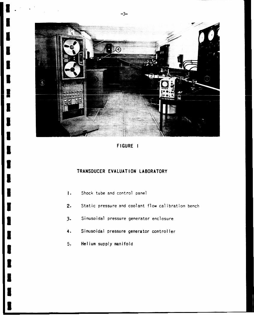
use of spec ia l i zed equipment. A s a par t of t h i s program, Battelle has es tab l i shed
a sepa ra t e laboratory f o r t ransducer eva lua t ion as shown i n Figure I. The NASA-
suppl ied equipment i n t h i s laboratory includes a s t a t i c pressure c a l i b r a t i o n
bench, a coolant flow test bench, a s inusoida l pressure generator, a shock tube,
-3-
FIGURE I
TRANSDUCER EVALUATION LABORATORY
1 .
2,
3. Sinusoidal pressure generator enclosure
4.
5. Helium supply manifold
Shock tube and control panel
S t a t i c pressure and coolant f low cal i b ra t i on bench
Sinusoidal pressure generator control l e r
8
-4-
and some accessory equipment such as constant-voltage suppl ies , charge ampl i f ie rs ,
f low meter, and gas-supply systems.
S t a t i c Pressure Ca l ib ra t ion
The s ta t ic pressure c a l i b r a t i o n bench setup i s s u i t a b l e f o r accurate
determinat ion of pressure response including hys t e re s i s , l i n e a r i t y , repro-
d u c i b i l i t y , and response t o changes i n equi l ibr ium temperature. Many t r ans -
ducers have dynamic cooling systems, e i t h e r open cyc le i n which a l i q u i d o r gas
coolan t is exhausted i n t o the pressure-source chamber or closed cyc le i n which
a l i q u i d coolant is c i r cu la t ed through t h e t ransducer . The s t a t i c c a l i b r a t i o n
bench i s s u i t a b l e f o r determining t h e e f f e c t s of temperature, pressure, and flow
rate of t h e coolant on the pressure response of t h e transducer.
I' The s ta t ic pressure c a l i b r a t i o n range extends t o 2000 p s i , a H e i s e
tes t gage being used as a working c a l i b r a t i o n s tandard.
p re s su re r egu la to r permits small incremental changes i n pressure without over-
shoot. Although t h e laboratory gage is assumed t o have an accuracy of only
0.25 percent, supporting c a l i b r a t i o n equipment ( R u s h dead-weight testers) i s
accura te t o 0.04 percent with t r a c e a b i l i t y t o t h e National Bureau of Standards
maintained.
A Grove pushbutton gas-
Coolant Flow Cal ib ra t ion
I n many t ransducers t h e dynamic cool ing system i s c r i t i ca l t o the
performance of t h e instrument.
d i s t i l l e d water can be forced through a t ransducer a t var ious pressure leve ls .
Working pressures t o 1600 p s i can be provided.
t o measure l i q u i d flow rates i n t h e range 0 . 1 t o 1 .0 gal/min (0.014 t o 0.14
lb / sec) .
A closed water-supply system i s so assembled t h a t
A turbine- type flowmeter i s used
This coolant flow system i s normally used i n conjunct ion with a s t a t i c
pressure ca l ib ra t ion , a s t h e e f f e c t s of coolant system operat ing parameters on
t h e pressure readout are o f t e n s ign i f i can t .
c a l i b r a t i o n equipment i s shown i n Figure 11.
The s t a t i c pressure and coolant flow

-5-
I I 1 I I
I I I I E I I 1
I I 1 1 I I
I B
FIGURE I 1
S T A T I C PRESSURE AND COOLANT FLOW CALIBRATION BENCH
I.
2. Static pressure panel
3. Nitrogen supply
4. High-pressure water supply
5.
Flow cal i brat ion panel
Distil l e d water storage and receiver
-6-
S inusoida 1 Pressure Generator
Driving a transducer with s inusoidal pressure pulses covering a range
of f requencies permits d i r e c t comparison of t he amplitude and phase of i t s output --:cL +L- -.+.... t ..G 2 ~n--.- n t c t i n a s v a t + a n s A r r r P y - A r;rnallma+ir ninl lnoidal " & b r a L.1- vubru' YL -*--"..-* -- -------_ - _ _ - - _ __.
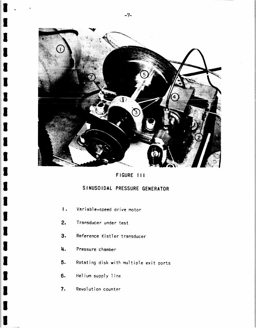
pressure generator (SPG) has been developed as shown i n F igure 111.
opera tes by feeding high-pressure helium i n t o a small chamber, t he o u t l e t of
which is through a choked o r i f i c e tha t i s i n t e r m i t t e n t l y opened and closed.
As can be seen i n Figure 111, t h i s pulsing i s provided by a r o t a t i n g d i sk with
a series of ho les near t h e r i m . A variable-speed motor d r i v e for t h i s d i sk
c o n t r o l s t he frequency.
This device
The usua l chamber p r e s s u r e averages 250 p s i with peak-to-peak pressure
The out- o s c i l l a t i o n s varying from 150 p s i a t 1000 cps t o 12 p s i a t 10,000 cps.
put of a monitor transducer ( K i s t l e r 601) known t o have l i n e a r dynamic response
i n t h i s frequency range i s compared on a dual-beam osc i l loscope with t h e test
t ransducer and t h e two t r a c e s are photographed.
and phase can be made from such photographs.
Direct comparison of amplitude
Although t h e equipment i s normally operated between 1000 and 10,000 cps,
t h e operat ing frequency can be extended t o 30 c p s a t t he low end and t o 18,000 cps
a t t h e high end with some reduct ion i n r ep roduc ib i l i t y and accuracy of s inusoida l
wave form. This device is a b l e t o accommodate t ransducers which i n j e c t a coolant
a s wel l as t ransducers which are connected t o the pressurized chamber with a
r e s t r i c t i n g flow passage. I n e i t h e r case, the e f f e c t s of t h e t ransducer on t he
pressure-time p a t t e r n generated within the SPG must be considered. Fortunately,
the re ference t ransducer i n t h e SPG chamber does respond t o the a l t e r e d pressure
pulse so t h a t a t r u e r ep resen ta t ion of t h e a c t u a l pressure pulse i s provided.
Shock Tube
A shock tube technique has been developed a t Pr ince ton and elsewhere
f o r dynamic response ana lys i s of transducers.
l eve ls , gases, and geometry, a d i sc re t e pressure rise of 1000 p s i can be imposed
on the t ransducer wi th in one microsecond, followed by a constant-pressure period
With s u i t a b l e choice of pressure
8 - I 1 8 I II
I I I I 8 I 1 I I I I I 1 II I
t 0
1 .
2.
3.
4.
5.
6.
7.
-7-
FIGURE I l l
SINUSOIDAL PRESSURE GENERATOR
Va r i a bl e-s peed d r i v e mo t o r
Transducer under t e s t
Reference K is t 1 e r transducer
Pressure chamber
Rotat ing disk w i t h m u l t i p l e e x i t por ts
He1 ium supply 1 ine
Revolution counter

-8-
l a s t i n g about 4 mil l iseconds. The pressure pulse i s s u f f i c i e n t t o "ring" o r
d r ive t h e t ransducer i n t o o s c i l l a t i o n .
long enough f o r observat ion of t h e decay r a t e of t h i s o s c i l l a t i o n .
The succeeding steady-pressure period i s
a- * - - - n A - . n - - +-----en cc t h i s + - k , 5: L l _ i s n l - x m r l i ) ~ 2" c~,-5ll-~~~nn r ---- - r- -J -- r - C & Y - Y Y Y - - - ---
and photographed. This record of s i g n a l amplitude versus t i m e i s then transposed
onto input cards and f e d i n t o a d i g i t a l computer.
response amplitude versus frequency and phase angle versus frequency f o r t he
t ransducer .
by comparison with mathematically derived r e l a t i o n s should t h i s be desired.
The computer c a l c u l a t e s
The na tu ra l frequency for zero phase angle can then be determined
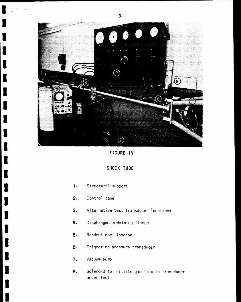
Figure I V shows t h e shock tube and con t ro l panel i n s t a l l e d i n the
laboratory. The burs t diaphragm, located i n t h e midpoint f lange, i s broken by a
small increment i n d r i v e r pressure, and the shock is dr iven toward t h e near end
of t h e tube where t h e t ransducer i s located. The osc i l loscope i s shown with t h e
camera removed.
Other F a c i l i t i e s Avai lable
Addit ional test f a c i l i t i e s have been made by B a t t e l l e t o support t h e
t ransducer eva lua t ion equipment supplied by NASA. The more pe r t inen t of these
include v i b r a t i o n equipment, rocket t e s t f a c i l i t i e s , and high-speed s i g n a l
recording and da ta ana lys i s instrumentation.
I n many rocket motor appl icat ions, h igh- in tens i ty v ib ra t ions are t r ans -
mit ted through t h e s t r u c t u r e during operation, and these may o r may not inc lude
t h e same frequency as those being observed i n t h e combustion chamber.
s e n s i t i v i t y of t he t ransducer t o s t ruc ture-appl ied v ib ra t ions during use is,
theref ore, of importance.. Electromagnetic v i b r a t o r s (shakers) a r e ava i l ab le
with which the t ransducer can be v ibra ted along any axis while a s t a t i c pressure
c a l i b r a t i o n i s obtained. With a transducer weight of 1/10 lb , the a v a i l a b l e
v i b r a t i o n equipment w i l l provide v ib ra t ions of 100 g over a frequency range from
100 t o 20,000 cps . Although more severe v ib ra t ions may be encountered i n some
rocket motor appl ica t ions , t h i s type of v i b r a t i o n ana lys i s w i l l demonstrate t h e
The
-9-
I .
2.
3.
4.
50
6.
7.
8-
FIGURE I V
SHOCK TUBE
Struc tura l support
Control panel
A1 ternat i ve t e s t transducer 1 ocat ions
Diaphragm-containing flange
Readout osc i 1 1 oscope
Tr igger ing pressure transduce.r
Vacuum pump
Solenoid t o i n i t i a t e gas flow t o transducer under t e s t
-10-
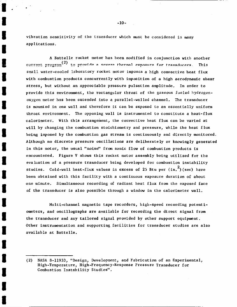
v i b r a t i o n s e n s i t i v i t y of t h e transducer which must be considered i n many
app l i ca t ions .
A B a t t e l l e rocket motor has been modified i n conjunction with another
(2) ce n t n l r i r l c r a qpvcrrp therm1 Pxpnsiircr fnr trnnsd1rrer.s. r--0--- This r - - ,-...- -0-t --C.*trJm --- - ---- small water-cooled laboratory rocket motor imposes a high convective hea t f l u x
with combustion products concurrent ly with imposit ion of a high aerodynamic shear
stress, but without an appreciable pressure pulsa t ion amplitude.
provide t h i s environment, t h e rectangular th roa t of the gaseous fueled hydrogen-
oxygen motor has been extended i n t o a paral le l -wal led channel. The t ransducer
i s mounted i n one wal l and the re fo re it can be exposed t o an e s s e n t i a l l y uniform
th roa t environment. The opposing w a l l is instrumented t o c o n s t i t u t e a hea t - f lux
ca lor imeter . With t h i s arrangement, the convective hea t f l u x can be var ied a t
w i l l by changing the combustion stoichiometry and pressure, while t he hea t f l u x
being imposed by the combustion gas stream i s continuously and d i r e c t l y monitored.
Although no d i s c r e t e pressure o s c i l l a t i o n s a r e de l ibe ra t e ly o r knowingly generated
i n t h i s motor, t h e usua l "noise" from sonic flow of combustion products is
encountered. Figure V shows t h i s rocket motor assembly being u t i l i z e d f o r t h e
eva lua t ion of a pressure t ransducer being developed f o r combustion i n s t a b i l i t y
s tud ie s . Cold-wall hea t - f lux values i n excess of 25 Btu p e r ( i n . ) ( s ec ) have
been obtained with t h i s f a c i l i t y w i t h a continuous exposure dura t ion of about
one minute. Simultaneous recording of rad ian t heat f l u x from the exposed f ace
of t he t ransducer is a l s o poss ib le through a window i n t h e ca lor imeter w a l l .
I n order t o
2
Multi-channel magnetic tape recorders , high-speed recording po ten t i -
ometers, and osc i l lographs are ava i l ab le f o r recording t h e d i r e c t s i g n a l from
t h e t ransducer and any t a i l o r e d s igna l provided by o the r support equipment.
Other instrumentat ion and supporting f a c i l i t i e s f o r transducer s tud ie s are a l s o
ava i l ab le a t B a t t e l l e .
(2) NASA 8-11933, "Design, Development, and Fabr ica t ion of an Experimental, High -Temperature , High -Frequency -Res pons e P r e s sure Trans duc e r f or Combustion I n s t a b i l i t y Studies".

. -SI,- -
Photograph ld
Sectional Schematic
FIGURE V
H I G H HEAT-FLUX EXPOSURE ASSEMBLY ON
1.
2.
3-
4.
5.
6.
7.
8.
9.
IO.
I I .
Rectangular nozzle throat extension
Water-cooled transducer nozzle b l ock
Water-cooled window Mock, alsc a ca
Pressure transducer
Combust i on chamber
Quartz w i ndow
Radiat ion pyrometer, "Rayotube"
Refractory ceramic po t t ing mater ia l
Brass re ta in ing body
Cooling water l i n e s t o nozzle blocks
I g n i t i o n wi re f o r rocket combustion
ROCKET MOTOR
o r i met e r
-12-
I 1 - +
‘ I I 1
IMPROVEMENTS NEEDED I N EVALUATION CAPABILITIES
I n the course of t h i s program discussions were conducted with many
ind iv idua l s who are concerned with the development, manufacture, and use of ~ ~ P _ S C ~ T P _ ~ ~ = ~ ~ ~ i ~ r ~ r s - T n thpsr- r l isr i issinns s p r i a l a t tc ln t ion was directed
toward t h e required c h a r a c t e r i s t i c s and t h e evaluat ion of transducers s u i t a b l e
f o r t h e measurement of t h e t r a n s i e n t pressures which occur during combustion
i n s t a b i l i t y i n l iquid-propel lant rocket motors.
Four a reas w e r e i d e n t i f i e d where improvements w e r e so re ly needed.
These w e r e :
The a b i l i t y t o impose appropriate v ibra t ions through t h e
transducer housing.
The a b i l i t y t o provide control led and reproducible exposure
a t high heat-f lux leve ls .
The a b i l i t y t o make dynamic pressure c a l i b r a t i o n s and t o
perform l i f e t e s t i n g a t both high amplitudes and high
frequencies . The a v a i l a b i l i t y of a n accurately character ized unstable
combustion environment f o r exposure evaluat ions.
Externa l ly Applied Vibrat ions
The v ib ra t ion l e v e l encountered i n some rocket motor s t r u c t u r e s
apparent ly reaches very high in t ens i ty . Estimates of i n t e n s i t y appreciably above
1000 g have been made. These v ibra t ions may or may not be coupled t o t h e combus-
t i o n i n s t a b i l i t i e s , and they may be received by the transducer i n a d i r e c t i o n
e i t h e r along or across the transducer axis. With s u i t a b l e equipment, undesirable
resonance or v ib ra t ion of transducer components over a wide range of f requencies
can be i d e n t i f i e d e i t h e r a s an output s i g n a l o r by v i sua l observation of ex te rna l
components with a stroboscopic l i g h t source.
-13-
A s noted previously, Ba t t e l l e has made ava i l ab le electromagnetic
v i b r a t o r s which can impose an acce le ra t ion magnitude of 100 g over a frequency
range of from 100 t o 20,000 cycles per second.
t i o n s a r e about an order of magnitude less severe than might be encountered i n
motor app l i ca t ions , t hese can demonstrate t he s e n s i t i v i t y of a n instrument t o
the v i b r a t i o n a l equipment.
Although these laboratory vibra-
Extended Steadv-State H e a t Flux
An a v a i l a b l e exposure f a c i l i t y providing continuous, reproducible, and
c o n t r o l l a b l e convective h e a t f l u x was described e a r l i e r i n t h i s r epor t . The
25 Btu per ( i n . ) ( sec) capac i ty of the present equipment roughly matches t h e hea t
f l u x encountered i n conventional l iquid-fueled motors. Combustion pressures
appreciably above 1000 p s i , as are now being considered i n both laboratory and
f l i g h t motors, make an eva lua t ion f a c i l i t y des i r ab le with a hea t - f lux c a p a b i l i t y
of a t least 50 Btu per ( in . ) ( sec ) . Current t ransducer development programs
being conducted by Battelle and others w i l l r equi re such a n evaluat ion f a c i l i t y
t o determine and t o demonstrate t h e heat-f lux c a p a b i l i t y of new transducers .
2
2
Although t h e rocket motors present ly i n use a t Battelle a r e l imi ted i n 2 hea t - f lux capac i ty t o about 25 Btu per ( in . ) ( s e c ) , t he re appear t o be no
insurmountable obs tac les i n using t h e same approach t o obta in a s teady-s ta te
convective hea t f l u x of 50 or 60 Btu per ( i n . S ( s e c ) .
convective hea t f l u x with a gas stream which i s near equi l ibr ium i s genera l ly
preferred, although f o r some instruments, an apprec iab le con t r ibu t ion by r a d i a t i o n
o r su r face chemical e f f e c t s might b e acceptable .
The imposit ion of a
Osc i l l a t ing Pressure Generators
The SPG cu r ren t ly ava i lab le , and o thers used by var ious labora tor ies ,
have severe pressure amplitude and frequency l imi t a t ions .
a v a i l a b l e with t h e B a t t e l l e SPG is l o w e r than t h e average imposed pressure by a
f a c t o r of 20 when operat ion i s a t about 10,000 cps .
o s c i l l a t i o n s , t he pressure amplitude becomes equal t o t h e average pressure.
The amplitude cu r ren t ly
I n some rocket combustion
Any

1 * -
I I I
I I II i 1 I 4 I I I i I I 8 I I I
e
I m
-14-
apprec iab le increase i n amplitude w i l l permit b e t t e r evaluat ions of the dynamic
response and, i nc iden ta l ly , provide a more r e a l i s t i c environment when the f a t i g u e
l i f e of t h e t ransducer is considered.
A s p resent ly i n s t a l l e d , t h e SPG uses room-temperature helium as t h e
working gas. Heating t h e gas would increase the pressure amplitude because of t he correspofidi-ji i -~rease in aenic b - e l ~ i t y . *dse =f h-rclrnrr-rr ~ . ~ n * i l .." rl iqxxwe
the pressure amplitude ava i l ab le with the SPG, e spec ia l ly a t f requencies below
10,000 c p s . The use of hydrogen would a l s o reduce gas consumption cos t s . One or
both of t h e s e approaches may be required f o r s p e c i a l appl ica t ions o r when pressure
amplitudes must be pushed t o the highest poss ib le leve l . When t h e t ransducer
design i s compatible with t h e use of a l i qu id as the pressure-appl icat ion f l u i d ,
t h e pressure amplitude could e a s i l y be increased t o any desired value.
Another improvement i n laboratory pressure generators which would
m a t e r i a l l y a s s i s t those making transducer evaluat ions would be t o use a gas hot
enough t h a t an appreciable hea t flux could be appl ied simultaneously with t h e
o s c i l l a t i n g pressure . The advantage of such a procedure over t he use of an
o s c i l l a t i n g rocket motor d i r e c t l y is t h a t the frequency and pressure l e v e l can
be independently control led, and t h e combined environment can be more accura te ly
charac te r ized f o r c a l i b r a t i o n purposes.
Although l imi ted t o about 5 p s i p ressure amplitude a t the upper f r e -
quency l i m i t of 18,000 cps, t h e present SPG i s a valuable d iagnos t ic c a l i b r a t i o n
device. U n t i l improved equipment is ava i lab le , it is uniquely s u i t e d t o provide
cont r o l l ed , reproducible, and w e l l -monit or ed pressure pulsa t ions .
Osc i l l a t ing Rocket F a c i l i t y
A widely needed f a c i l i t y f o r t h e evaluat ion and demonstration of
t ransducers i s an uns tab le rocket engine. I n most cases t h e t ransducer developer
has t o r e l y on customers who a r e users of h i s product t o supply performance da ta
obtained i n t h e in t eg ra t ed exposure environment. I n general , t hese da ta are not
obtained i n known and reproducible environments, a s t he motor f i r i n g condi t ions
I t
1 1 I
I I I I I I I I I I i I I I I i I
II m
-15-
a r e governed or s e t t o s a t i s f y demands not d i r e c t l y r e l a t e d t o transducer evalua-
t i o n .
combustion environment which w a s both w e l l charac te r ized and reproducible would
be very usefu l i n t h e development and eva lua t ion of pressure t ransducers .
The a v a i l a b i l i t y of a rocket f a c i l i t y providing a severely o s c i l l a t i n g
SUMMARY
The measurement of t r ans i en t pressures i n rocket combustion chambers
imposes severe performance requirements on pressure transducers, e spec ia l ly during
severe combustion i n s t a b i l i t i e s . Technical and experimental c a p a b i l i t i e s have
been e s t ab l i shed f o r t he appropr ia te eva lua t ion and diagnosis of dynamic pressure
t ransducers intended f o r t h i s appl ica t ion . The laboratory environmental condi-
t i ons c u r r e n t l y ava i l ab le a re suuunarized below. This laboratory i s now ready a t
B a t t e l l e f o r use i n transducer s tud ies required by the t echn ica l community.
S t a t i c G a s Pressure Ca l ib ra t ion t o 2000 p s i
Gas Coolant, Helium or Hydrogen
Flow rate a s required H e l i u m pressures t o 6000 p s i
Liquid Coolant, D i s t i l l e d Water
0.1 t o 1 gal/min flowmeter Pressures t o 1600 p s i
O s c i l l a t i n g Gas Pressures (Sinusoidal) a t Ambient Temperatures
250 p s i average pressure usua l ly used 30 t o 18,000 cps 12 p s i amplitude a t 10,000 cps G a s bleed systems accommodated
Discre te Pressure Step (Shock Tube)
1000 p s i r i s e i n about 1 microsecond 4 mil l isecond dwell t i m e Gas bleed systems accommodated
Vibrat ions Applied External ly
100 g acce le ra t ions t o a 1/10-lb t ransducer 100 t o 20,000 cps
Convective Heat Flux, Rocket Motor
25 Btu pe r ( in.2) (sec) maximum High shear i n nozzle throa t exposure Steady s t a t e o r var iab le with t i m e Hydrogen-oxygen fueled with v a r i a b l e stoichiometry.