Embed Size (px)
Citation preview

Evaluation and retrofitting of a concretewall building placed in Bucharest usingmultistage rubber bearings
V.V. Oprisoreanu & D. ZamfirescuTechnical University of Civil Engineering Bucharest, Romania
ABSTRACT:This paper presents the seismic evaluation of an existing reinforced concrete shear wall structure located inBucharest and proposes a retrofit solution based on Seismic Base Isolation Method using Multi-Stage RubberBearings. The seismic evaluation was based on static nonlinear analysis (Push-Over) on a 3D model. Nonlinearbehaviour was assumed for the shear walls, beams and columns. The strength and displacement capacities wereassessed using the European code (EUROCODE 1998-3). A retrofitting solution using Seismic Base Isolationmethod is designed. The isolating layer was obtained using several types of Multi-Stage Rubber Bearings, whichwere designed to sustain the loads and imposed displacement. The efficiency of the retrofitting solution wasdetermined through a Time History analysis performed on the 3D model. The conclusion of the study is that thebase isolation method based on multi-stage devices can represent an alternative to the classical retrofittingmethods even for areas with high predominant period earthquakes that impose large displacements demands.
Keywords: retrofitting, multi-stage rubber bearing, seismic base isolation.
1. INTRODUCTION
An important problem regarding the seismic risk in Romania is the existence of a large number ofbuildings designed and built before the occurrence of the 1977 Vrancea earthquake, which revealed thevulnerability of the multi-storey RC buildings, especially in the Romanian Plane region. The pulse-type earthquake having a large predominant period of 1.6s induced large displacement demands, and,as a result a number of about 28 multi-storey RC buildings collapsed and many other sustained heavydamage. Generally these buildings were characterized by a non-ductile behaviour and particularly theRC frames structures by low lateral force strength.
The current study presents the evaluation and the retrofitting proposal for a building designed and builtin Bucharest during the 60’s. The structural system of the building consists from shear walls havinglarge flexural capacity but low shear capacity. This structural type was used on large scale in thatperiod in Romania for apartment buildings. In the current study the evaluation of the shear capacitywas done according to Level Three (N3) methodology considering the procedure defined in theEuropean code (Eurocode 1998 part 3). In case of the retrofitting, the adopted strategy implies thereduction of the seismic demands. The reduction of the seismic demand was done through a BaseIsolation system obtained using Multistage Rubber Bearings. The base isolating system was designedto ensure that only a small amount of seismic energy reaches the superstructure of the building thus theseismic demand on the structural elements decreases.
2. THE ANALYSED BUILDING (GENERAL PRESENTATION)
The analysed building is a shear wall structure designed and built during the 60’s; the building has 11stories above the ground. The plan conformation of the building can be seen in figure 1. The structural

system designed to carry the lateral seismic load is dominated by two large T section walls placed oneach end of the structure.
Figure1. Story Plan
In the X direction, these walls are virtually the only two vertical elements capable to carry the seismicload on this direction. In the Y direction there is a set of lamellar concrete walls, also, but thebehaviour under seismic loads is still dominated by those two T shape elements. In the current paper,only the results obtained for these T shape walls (named below as DT walls) are presented in detail.
Table1 Longitudinal and transversal reinforcement percent for DT walls
StoryVertical Horizontal
End (%) Web (%) End(%) Web (%)
Groundlevel
0.65 0.38 0.1880.2230.497 0.334 0.107
0.863 0.334 0.134
E1-E20.668 0.214 0.094
0.1260.447 0.254 0.1880.485 0.254 0.094
E3-E90.631 0.048 0.094 Does not
exist0.389 0.111 0.188E10 0.631 0.216 0.094 0.126
Table 1 presents the longitudinal and transversal reinforcement percent for the DT wall section. Forthe DT wall section the reinforcement ratio is different from one part of the wall to another (at thesame level), that is the reason why in table 1 there are different reinforcement ratios at the same level.This table should provide a qualitative rather than a quantitative view of the wall reinforcement. Itshould be mentioned that, between the levels three and nine the horizontal reinforcement in the webdoes not exist. It was a common practice during those years not to include horizontal reinforcement inthe wall. Also we should have in mind that the web thickness is very small (15cm) compared with theheight of the section (7.3m on X direction and 8.75m on Y direction).
3. BUILDING EVALUATION
The shear capacity of the DT wall was done according to the N3 methodology considering theEuropean Code EC8 part 3. The structure was modeled in the Perform3D software assuming anonlinear behaviour. The nonlinear behavior of the structural elements was modelled as follows [3]:

- For the reinforced concrete beams and columns a lumped moment-rotation hinge model wasconsidered at each end of the element; for the columns the interaction between the capacityand axial force was accounted.
- For the structural walls a fiber model was used; for each fiber (concrete or reinforcement bar)a behavior rule was defined;
The materials used in the model were concrete B200 (C12/15) and steel OB37 (fyd=210 MPa). Themean strength values corrected by global/local safety coefficients were considered for each material.The safety coefficients are defined in the above mentioned code for each loading type.
The seismic load was modelled by a set of horizontal forces placed in the mass centre of each floor(considering 5% accidental eccentricity). The vertical distribution of these horizontal forces wasdetermined according the fundamental vibration modes on X and Y direction. The displacementdemands corresponding to each limit state were assessed from the mean response of the equivalentsingle degree of freedom system to five artificial accelerograms compatible with the design spectrum(using the appropriate equivalency coefficients).
Having in mind that the behavior of the structural system under seismic load is dominated by thebehavior of the two DT walls, only the results regarding these walls will be presented in detail in thecurrent paper. Because the section of the DT wall is not symmetrical in relation with the Y axis, thereare two different loading situations: one where the compression zone is in the web and another wherethis zone is in the flange.
Figure2. Shear Force –Rotation diagram at the base of DT wall X direction (compression in web –left part andin the flange – right part)
Figure 2 presents the Shear Force –Rotation diagrams recorded at the base of DT wall. The Rotationparameter was chosen for these diagrams mainly because in the European norms the shear capacityvalue is related with the rotation (through μθ parameter). The left diagram presents the situation inwhich the compression zone is in the web and the right diagram when it is in the flange. With red lineit is represented the shear capacity controlled by the stirrups (VR), with yellow line the shear capacitycontrolled by the concrete web crushing (VRmax) and the three verticals lines represent the rotationsvalues associated with the three limit states considered in the study (SLS, ULS and SLSV).
Each limit state was defined considering the following Mean Returning Intervals: for SLS theassociated MRI is 50year, for ULS the associated MRI is 100 years and for SLSV the associated MRIis 475 years. The usage of the displacement demand concept (computed for each limit state) inassociation with shear force analysis is not very common. However, in the current study this approachwas preferred mainly because it highlights the fact that even for a moderate seismic event (associatedto SLS) a high damage level is expected for the studied building. The wall shear capacity is reachedfor a rotation much smaller than the rotation associated with SLS limit state. However, it should bementioned that when the compression zone is in the web of the T section the shear capacity is
0
1000
2000
3000
4000
5000
6000
7000
0 0.002 0.004 0.006 0.008 0.01 0.012
Sh
ear
Fo
rce(
KN
)
θ (Rad)
DT PushX-DTi (Base)Eurocode 8 - 3
PushXVRVRmaxSLSULSSLSV
0
1000
2000
3000
4000
5000
6000
7000
0 0.002 0.004 0.006 0.008 0.01 0.012
Sh
ea
rF
orc
e(K
N)
θ (Rad)
DT PushX-DTc (Base)Eurocode 8 -3
PushXVRVRmaxSLSULSSLSV

controlled by the stirrups and when the compression zone is in the flange the capacity is controlled bythe diagonal crushing. For this direction the ratio between the total yielding force and the total weightof the building is 0.21, the displacement demand for ULS is 0.14m. The R3 coefficient (the ratiobetween the shear capacity and the shear demand associated with ULS limit state) is 0.18 for oneloading case and 0.23 for the second loading case. The conclusions presented above (for the seismicload on X direction) are adequate for Y direction too, and are not presented in detail. The wall shearcapacity is reached for a lateral displacement lower than the one associated to SLS limit state.
A general conclusion of the evaluation process is that the DT wall has a large flexural capacity (mainlydue to the geometry of the section) but in the same time an important deficit regarding the shearcapacity. The evaluation process revealed that the shear capacity at the base of the wall is reached forlateral displacements much smaller than those associated with the SLS limit state. Furthermore, forULS, the induced shear forces exceed the capacity on the entire height of the wall. This type ofbuilding is prone to damages even for small seismic actions, mainly because the building has highstiffness and flexural capacity (due to the geometrical configuration), but small shear capacity.
4. RETROFITTING OF THE BUILDING
Any retrofitting strategy must start from the general conclusion presented in the previous section. Theretrofitting solution should be able to increase the shear capacity of the building without increasing theflexural capacity. One possible strategy, considered a “classic” approach, involves the shearstrengthening of the RC walls. This solution involves dramatic and long duration disturbance offunctionality of the building. Furthermore, the ductility capacity of the walls has to be increased and itcannot be done without major interventions at the base of the structure. Another solution is to limit theenergy that reaches the structure in case of a seismic event. This energy limitation can be obtainedthrough a Base Isolation solution. In the current study the second approach was preferred.
Having in mind the particularities of the seismic load associated with the Bucharest region (longcontrol periods, Tc=1.6s), a classical base isolation solution will lead to a new set of problemsassociated mainly with the stability of these classic isolation devices for large imposed displacements.Previous studies [1] [2] performed by the authors revealed the fact that in order to overcome the largedisplacement demand imposed by the seismic load, it is needed to ensure a large damping level in theisolating layers and/or to use large isolation devices. In both situations the efficiency of the isolationsystems will be significantly reduced.
In order to overcome the problems associated with a classical base isolation system the authorsdecided to use Multistage Rubber Bearings devices. Although in the past, these devices were mainlyused to isolate light buildings [3] (which is not the case in the current study) the main characteristics ofthe devices (small lateral stiffness with large displacement capacity) made them the ideal candidates tobe used in this study.
4.1 Design of the Multistage Rubber Bearings
The multi-stage rubber bearings are the rubber bearings which mainly consist in small rubber deviceslocated at every of the four corners of one common stabilizing steel plate (see figure 3). Consequently,the horizontal displacement capacity is considerably increased while the horizontal stiffness of thedevice is maintained on a lower value (thus a longer isolated period can easily be achieved). For alarge horizontal displacement the classical device tends to have major stability problems, while for thesame displacement a multi-stage device exhibits a stable behavior. The conclusion is that the multi-stage devices are much more suitable for very large imposed lateral displacements.
The design of the multistage rubber devices implies performing an analysis regarding the stability ofthe device considering both buckling limit state and roll-out limit state. Even if a roll-out failure canoccur only in case of dowelled shear connections (which is not the case here) a good design practice is

to limit the total lateral displacement to the roll-out value [4]. Regarding the buckling limit state, incontrast with the classic case, a multistage device can exhibit two distinct buckling modes: first(named in the study “local” buckling) which implies the failure of one individual device in a certainlayer and the second which implies the buckling of the entire multistage device (named in the study as“global” buckling). The equations which characterize those two situations can be found in the table 2.
Figure3. Classic Rubber Bearing versus Multistage Rubber Bearing
Table2 Multistage rubber bearings (Stability limit states)
The parameters presented in the table 2 are: me – the number of elastomeric devices per layer; ne – thenumber of layers; G – shear modulus of the elastomeric devices; Sl – shape factor for the elastomericdevices; Al/At – the area for one elastomeric device/ for all elastomeric devices in one layer; rl/rt –radius of gyration for one device/for the entire multistage device; tr
l – total height of the rubber for onedevice; tr – the total height of the rubber for the entire multistage device; Φl =2R – the diameter of oneelastomeric device; Pl – the vertical load on one elastomeric device, pl – the vertical pressure on oneelastomeric device and hl – the total height of one elastomeric device.
The values presented in table 2 were obtained considering that the distance between any elastomericdevice, on a single layer, is large enough to ensure that the critical force associated with the “local”
buckling limit state is smaller than the force associated with the “global” buckling (thus the distancebetween any two elastomeric devices is larger than 2dmin). The equation for the distance dmin wasobtained by imposing the above mentioned hypothesis.
The designing algorithm for the multistage devices relies on the assumption that the followingparameters are known: me – the number of elastomeric devices per one layer; ne – the number oflayers; G – shear modulus of the elastomeric devices; ξ – the damping proprieties of the elastomeric material; Sl – shape factor for the elastomeric devices. Considering a targeted horizontal isolatedperiod (Th) and a design response spectrum, a displacement demand can be easily computed. Imposinga value for the allowed distortion (γ = Total lateral displacement/total height of the multistage device) the geometry of the multistage devices is obtained. We should mention that the allowed distortionvalue used in the designing algorithm for the current study was γ=100%.
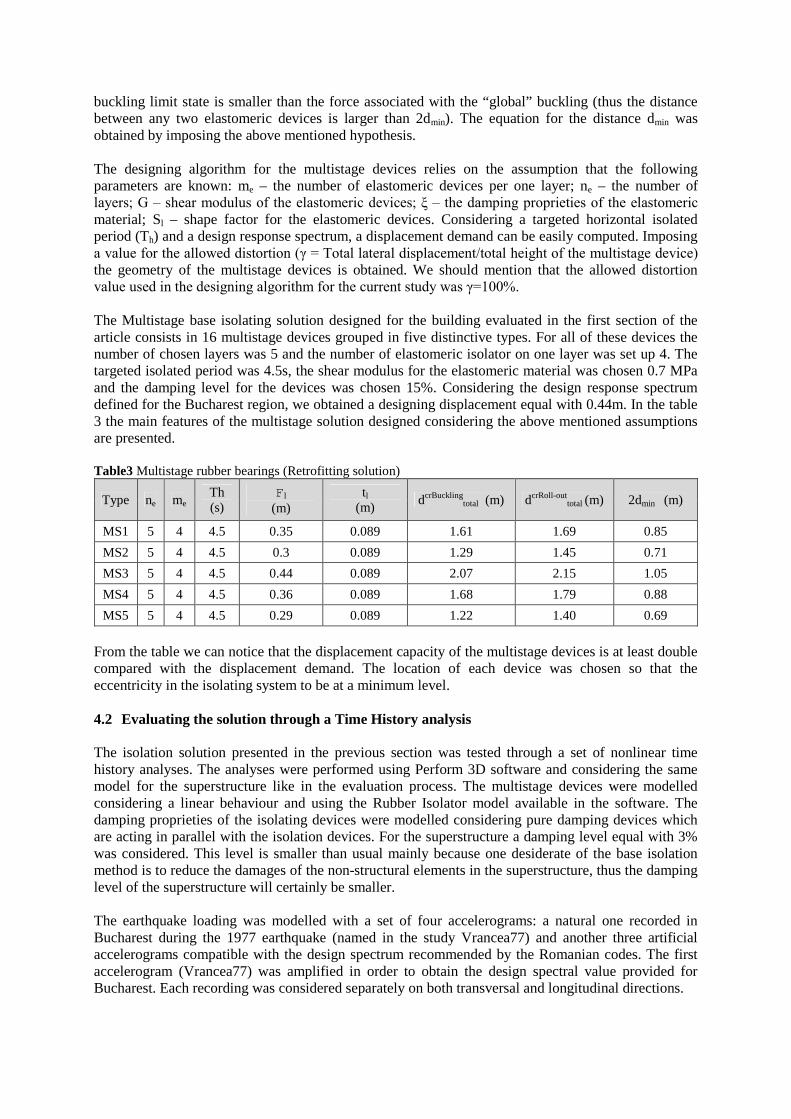
The Multistage base isolating solution designed for the building evaluated in the first section of thearticle consists in 16 multistage devices grouped in five distinctive types. For all of these devices thenumber of chosen layers was 5 and the number of elastomeric isolator on one layer was set up 4. Thetargeted isolated period was 4.5s, the shear modulus for the elastomeric material was chosen 0.7 MPaand the damping level for the devices was chosen 15%. Considering the design response spectrumdefined for the Bucharest region, we obtained a designing displacement equal with 0.44m. In the table3 the main features of the multistage solution designed considering the above mentioned assumptionsare presented.
Table3 Multistage rubber bearings (Retrofitting solution)
Type ne meTh(s)
Fl
(m)tl
(m)dcrBuckling
total (m) dcrRoll-outtotal (m) 2dmin (m)
MS1 5 4 4.5 0.35 0.089 1.61 1.69 0.85
MS2 5 4 4.5 0.3 0.089 1.29 1.45 0.71
MS3 5 4 4.5 0.44 0.089 2.07 2.15 1.05
MS4 5 4 4.5 0.36 0.089 1.68 1.79 0.88
MS5 5 4 4.5 0.29 0.089 1.22 1.40 0.69
From the table we can notice that the displacement capacity of the multistage devices is at least doublecompared with the displacement demand. The location of each device was chosen so that theeccentricity in the isolating system to be at a minimum level.
4.2 Evaluating the solution through a Time History analysis
The isolation solution presented in the previous section was tested through a set of nonlinear timehistory analyses. The analyses were performed using Perform 3D software and considering the samemodel for the superstructure like in the evaluation process. The multistage devices were modelledconsidering a linear behaviour and using the Rubber Isolator model available in the software. Thedamping proprieties of the isolating devices were modelled considering pure damping devices whichare acting in parallel with the isolation devices. For the superstructure a damping level equal with 3%was considered. This level is smaller than usual mainly because one desiderate of the base isolationmethod is to reduce the damages of the non-structural elements in the superstructure, thus the dampinglevel of the superstructure will certainly be smaller.
The earthquake loading was modelled with a set of four accelerograms: a natural one recorded inBucharest during the 1977 earthquake (named in the study Vrancea77) and another three artificialaccelerograms compatible with the design spectrum recommended by the Romanian codes. The firstaccelerogram (Vrancea77) was amplified in order to obtain the design spectral value provided forBucharest. Each recording was considered separately on both transversal and longitudinal directions.

The study was focused on four main aspects, the acceleration demand in the superstructure, thedisplacement demand both at the isolation layer and in the superstructure, the behaviour of thestructural elements in the superstructure (if these elements remained in the elastic domain and if shearcapacity is exceeded) and the shear demand in the walls. The analysis was performed separately onboth longitudinal and transversal direction. Due to the lack of space and the fact that the conclusionsare similar in both of these situations, only the results for the longitudinal direction will be presented.
4.2.1 Acceleration demand
Figure4. Acceleration demand on the longitudinal direction
Figure 4 presents the acceleration obtained in the longitudinal direction for each accelerogram. Bluecolour corresponds to the input signal, red colour to the acceleration recorded at the base level abovethe isolating system and the green colour to the acceleration recorded at the top level. We can concludethat from the acceleration point of view the proposed multistage system is very efficient. The inputacceleration is reduced in the superstructure almost twice and the amplification of the accelerationfrom base to top is insignificant. Lower levels of acceleration in the superstructure lead to smallerdegradations in the non-structural elements during the earthquake. A significant reduction of theacceleration in the superstructure is a common feature to every isolating system and is generatedmainly due to the lengthening of the structure period. The lengthening of the period will generatelarger displacement demands which are concentrated mainly at the isolating system level.
4.2.2 Displacement demandIn figure 5 it can be noticed the relative displacement demand recorded for the longitudinal directionfor each accelerogram considered in the analysis. With blue colour is represented the relativedisplacement recorded at the base level above the isolating system while with red colour the relativedisplacement recorded at the top level.

Figure5. Displacement demand on the longitudinal direction
From figure 5 two conclusions can be drawn. First, that the relative lateral displacement recorded atthe top level is almost identically with the one recorded at the base level (the diagrams are almostperfectly overlapped), thus the total drift of the superstructure is very small. A very small drift valueimplies that the superstructure is moving like a perfect rigid body and the damage level in thestructural and non-structural elements is very small.
The second conclusions is that, in all the situations considered in the analysis, the displacementdemand recorded at the base level is much smaller than the lateral displacement capacity of themultistage devices (see table 3). The smallest lateral displacement capacity is associated with themultistage device type 5 (MS5) and it is equal with 1.22m while the largest lateral displacementdemand is associated with Vrancea77 recording and it is equal with 0.6m. Therefore the capacity is atleast two times larger than the demand ensuring a safety factor (R3) equal with more than two.
Comparing the displacement demands recorded at the base level and the critical displacementsassociated with a Roll-out limit state presented in the table 3, we can conclude that the safety factor forthis limit state is larger than two, also. As mentioned in the previous section, according to the codes,the Roll-out limit state is associated with a non-bolted connexion, which is not the case here, but agood designing practice is to limit the total displacement to this value for the bolted connexions too.
4.2.3 Energy balance analysisThis part of the study was focused on the behaviour of the structural elements under dynamic loads.The main idea was to determine if the structural elements will remain in the elastic domain or if theywill have any inelastic behaviour. In order to determine if the structural elements will remain in theelastic range energy balance analyses were performed. Through this analysis it is possible to determinehow the input energy is dissipated during an earthquake. In the figure 6 it can be noticed the resultsobtained for the longitudinal direction. These results should be used only as a qualitative evaluationtool rather than a quantitative one.

Figure6. Energy balance analyses on the longitudinal direction
In the figure 6 we can notice the energy balance diagrams for the longitudinal direction. The figurepresents the energy dissipated during the analysis through various mechanisms: the kinetic energy inlight blue colour, the strain energy in purple colour, the energy dissipated through Beta-K mechanismin green colour (Rayleigh damping), the energy dissipated by the isolating system in red colour andfinally the energy dissipated through an inelastic behaviour of the structural elements in dark bluecolour. We can notice that the superstructure remains in the elastic range; the energy dissipatedthrough an inelastic mechanism is zero for all the cases. The main part of the input energy is dissipatedin the isolating system through a viscous mechanism. The conclusion is that the multistage isolatedsystem proposed in this study is extremely efficient, ensuring a behaviour in the elastic range for theentire superstructure, eliminating the necessity of increasing the ductility capacity of the structure.
4.2.4 Shear force evaluationIn the figure 7 it can be noticed the shear forces recorded at the base of DT wall on longitudinaldirection for each accelerogram. In the figure it is also represented the shear capacity for the DT wallassociated with the loading situation when the compression zone is in the web (red colour) and in theflange (blue colour). The conclusion is that the shear demand on the wall is smaller than the shearcapacity in all the cases analysed in this study. Therefore we can conclude that main purpose of theretrofitting process was fulfilled, the shear demand is significantly reduced.
The main conclusion on the evaluation is that the isolating system based on multistage rubber devicesis able to fulfil the requirements imposed by the codes: the acceleration demand in the superstructure issignificantly reduced and is not amplified from base to top, the displacement demands recorded at theisolated level are at least two times smaller than the displacement capacity of the multistage devices,the total drift of the superstructure is very small ensuring a smaller damage level in the non-structuralelements and as the energy balance analyses have shown, the structural elements remained in theelastic rage during the entire analysis.

Figure7. Shear Force recorded at the base of DT wall (longitudinal direction)
5. CONCLUSIONS
The current study analysed a shear wall building placed in Bucharest which is emblematic for a largecategory of buildings from Romania designed and built during the ’60. The building structure consistsof reinforced concrete shear walls, featured by complicated shapes and low or inexistent shearreinforcement. The main deficiencies of the shear walls are: shear capacity not associated to flexuralmoment capacity and lack of sufficient ductility due to absence of any seismic detailing and usage ofsmooth (plain) steel. Nevertheless, the structure has high stiffness and relatively high lateral forcestrength (for the 60's period) due to the geometry of the wall sections, and can be considered anadequate candidate for base isolation retrofitting solution.
The Multi-Stage Rubber Bearings solution for isolating layer was chosen. Although, these deviceswere mainly used to isolate light buildings (which is not the case in the current study), the authorsdecided to use these devices in order to overcome the designing problems generated by the longpredominant periods which are associated with the Bucharest area (Tc=1.6s), and the largedisplacement demands. Each device was designed considering the stability criteria associated withboth buckling and roll-out limit states. The efficiency of the retrofitting solution was determinedthrough a Time History analysis performed on the 3D FEM model. The analyses revealed the fact thatthe base isolating system based on multistage rubber bearings is very efficient. The demand on thesuperstructure is significantly reduced and in the same time the isolating system is very stable on largedeformations. The lateral displacement capacity of the devices is at least two times larger than thedisplacement demand imposed by the seismic load.
The general conclusion of the current study is that the base isolation method based on multi-stagerubber devices can represent an option for retrofitting and design of new structures in seismic areasfeatured by earthquakes with high predominant periods inducing large displacement demands, forwhich a classical base isolation solution can raise important problems regarding the stability of theclassical isolating devices.
REFERENCES
Oprisoreanu, V.V. and Serino, G. (2011) Design of base isolation devices Scientific Journal - MathematicalModeling – 4,
Oprisoreanu V.V. and Zamfirescu, D. (2011) Efficiency of base isolation for the romanian seismic conditionsScientific Journal - Mathematical Modeling – 1&2,
Nobuo, M., Youji, S., Takayoshi, K. and Takafumi, F. (2006) Development and application of tuned/hybridmass dampars using multistage rubber bearings for vibration control of structures. 13th WCEE – Papernumber 2243
Naein, F. and Kelly, J. M. (1999) Design of isolated structures. John WILEY & Sons, New-York