Embed Size (px)
Citation preview

Evaluating the field performance of windows and curtain walls of large buildings

WHITE PAPER
2
Executive Summary
The most common and costly problems associated with the in-service performance of the vertical building envelope of large buildings can be attributed to excessive air leakage and water intrusion. In particular, windows and curtain walls, as well as their interfaces with adjacent wall constructions, are critical elements in the performance of the vertical building envelope. Improved standards and design principles have contributed to significant, overall improvements in the performance of window and curtain wall systems, including resistance to water penetration, air leakage, wind load or condensation. However, the reality is that many recently constructed buildings still experience problems with the in-service performance of installed windows and curtain walls. Typically, these problems often result from poor fabrication or installation, or lack of adequate quality control.
This white paper discusses evaluating the field performance of windows and curtain walls of large buildings during the early stages of construction to validate as-built designs, and during later construction stages as a quality control measure. Through several practical examples, we’ll illustrate how large-scale field testing can be used to assess building envelope performance in large buildings. Our objective is to help increase awareness among members of the building community on the benefits and limitations of field testing in evaluating the performance of the large vertical building envelope.

WHITE PAPER
3
Performance requirementsWindows, and metal and glass curtain walls can constitute anywhere from 50 to 100 percent of the exterior cladding of large buildings in modern construction projects. An important architectural feature, these building elements represent a significant portion of the overall cost of a construction or renovation project and play an essential role in the performance of the vertical building envelope. Windows and curtain walls must be air and water tight, prevent condensation from occurring on the interior surfaces, and resist wind load and other exterior forces acting on the building envelope. Therefore, the evaluation is essential to minimize the risk of undesirable and costly problems during a building’s expected service life.
Figure 1: Metal and glass curtain wall - new construction (New York City, New York, USA)
Figure 2: Metal and glass curtain wall - building reclad (Montreal, Quebec, Canada)
Figure 3: Aluminum punch windows and precast concrete (Montreal, QC)
Figure 4: Aluminum punch windows and brick cladding (New York, NY)
Curtain walls can constitute anywhere from
50-100% OF THE EXTERIOR CLADDING of large buildings in modern construction projects

WHITE PAPER
4
The primary performance requirements that need to be considered during the design phase of each project include the following issues:
Any form of water infiltration or excessive air leakage to the interior of a building would be unacceptable to any building owner or occupant. Accordingly, having an appropriate level of resistance to water penetration and air leakage are two of the primary performance criteria for any window or curtain wall system. However, these are not the only focus of the performance criteria that need to be considered. Other factors include thermal performance, condensation resistance and wind load resistance.
Figure 5: Example of water infiltration within a curtain wall assembly
Figure 6: Example of water infiltration at a punch window assembly
Figure 7: Example of exterior icicle formation due to excessive air exfiltration within a curtain wall assembly
Figure 8: Example of excessive interior frost formation due to excessive air infiltration at a window/wall interface
Wind load resistance: Specified design pressures are typically established by the project’s structural engineer and are based on the building’s exposure classification, the building’s height, type and configuration. Window and curtain wall components must be designed to resist deflection and failure at the specified design pressure.
Resistance to water penetration: Performance requirements for resistance to water penetration vary depending on the building’s height, geographic location and exposure classification. In the U.S., ratings for resistance to water penetration are typically established as a function of the design wind pressure. In Canada, requirements for resistance to water penetration are determined by the driven rain wind pressure metric, a unique measure of climatic condition that has been established for each of more than 640 Canadian cities, based on their geographic location and a building’s installation height.
Condensation resistance: Condensation resistance performance requirements depend on the building’s geographic location and anticipated climate conditions, as well as the interior hygrothermal design conditions and type of building occupancy.
Air leakage resistance: Air leakage resistance performance requirements are often established by local building and energy codes and will vary for fixed and operable sections.
Ultimately, performance requirements need to be established for each project on a case-by-case basis, depending on building height and geographic location, exterior and interior design parameters, as well as the type of building occupancy.

WHITE PAPER
5
Industry standardsBoth the U.S. and Canada have industry standards that establish stringent performance requirements and testing methods for windows and curtain walls. In the U.S., the American Architectural Manufacturers Association (AAMA) and the National Fenestration Rating Council (NFRC) are the primary bodies that regulate the window and curtain wall industry. In Canada standards for the performance of windows are established by the Canadian Standards Association (CSA). There is no industry standard for the performance of curtain walls in Canada. In both the U.S. and Canada, testing methods to evaluate both laboratory and field performance are established by ASTM International (ASTM).
Here is a list of the principal industry standards that are commonly used to establish the laboratory performance criteria for windows and curtain walls throughout North America:
• AAMA/WDMA/CSA 101/I.S.2/A440: NAFS – North American Fenestration Standard, Specification for windows, doors and skylights. Outlines laboratory performance requirements applicable in the U.S. and Canada regarding resistance to water penetration, air leakage and wind load for windows, doors and skylights.
• CSA A440S1: Canadian Supplement to AAMA/WDMA/CSA 101/I.S.2/A440, NAFS – North American Fenestration Standard/Specification for windows, doors, and skylights. Outlines simplified methods for calculating minimum performance levels for resistance to water penetration, wind loads and snow loads for fenestration products on buildings in Canada and has to be used in conjunction with the NASF. However, it is important to note that this standard does not apply to storefronts, window walls, curtain walls and other glazed structures. For those products, Section 5.9.3 of the 2015 Canadian Building Code specifies the use of calculations detailed in CSA A440S1 to determine the minimum performance requirements for resistance to water penetration.
• AAMA 501: Methods of tests for exterior walls. Outlines laboratory performance requirements applicable in the U.S. for assessing resistance to water penetration, air leakage and wind load for metal curtain walls.
• NFRC 102: Procedure for measuring the steady-state thermal transmittance of fenestration systems. Outlines laboratory performance requirements applicable in the U.S. for assessing the thermal performance of fenestration products.
• AAMA 1503: Voluntary test method for thermal transmittance and condensation resistance of windows, doors and glazed wall sections. Outlines laboratory performance requirements applicable in the U.S. for assessing the thermal performance and condensation resistance of windows, doors and glazed wall sections.
• CSA/A440.2: Energy performance of windows and other fenestration products. Outlines laboratory performance requirements applicable in canada for assessing the thermal performance and condensation resistance of windows and other fenestration products.
Figure 9: Exterior mock-up test (AAMA 501) - UL – CLEB laboratory
Figure 10: Interior mock-up test (CAN/CSA-A440) - Air-Ins laboratory
Figure 11: Environmental test chamber at the UL – CLEB laboratory

WHITE PAPER
6
The following is a list of the principal industry standards that are commonly used to establish the field performance criteria for installed windows and curtain walls in North America:
• AAMA 502: Voluntary Specification for Field Testing of Newly Installed Fenestration Products. Outlines field performance requirements applicable in the U.S. for assessing resistance to water penetration and air leakage for windows and glass doors.
• AAMA 503: Voluntary Specification for Field Testing of Newly Installed Storefronts, Curtain Walls and Sloped Glazing Systems. Outlines field performance requirements applicable in the U.S. for assessing resistance to water penetration and air leakage for storefronts, curtain walls and sloped glazing systems.
• CAN/CSA-A440.4 (Appendix E): Field Testing of Window and Door Installations. Outlines field performance requirements applicable in Canada for assessing resistance to water penetration and air leakage for windows and doors.
Field performance evaluationThe previous section of this white paper summarizes the primary performance requirements and industry standards related to windows and curtain walls, and are intended to provide the reader with some basic background information on the subject. However, our main focus is the field evaluation of the performance of installed windows and curtain walls. Given the ever-growing complexity and variety of modern building envelopes, the evaluation of the performance of installed windows and curtain walls in the preconstruction and construction phases is essential in order to avoid undesirable and costly problems during the service life of the building.
In most projects of any significance, the performance of the window and curtain wall systems intended to form part of the building envelope are evaluated in an accredited testing laboratory prior to construction. However, it is equally important that the field performance of the installed products be evaluated during different phases of construction as a quality control measure. Site conditions, variations in the manufacturing process or the quality and experience of the field installation team are all factors that can impact the performance of the installed products or systems.
When considering field testing, the first step is to identify test areas that are representative of the most common elements of the building envelope. Typically, field testing is usually limited to three to six test areas due to budgetary and scheduling constraints. Therefore, obtaining the most representative sampling depends on the careful selection of the areas to be tested.
Test areas should be selected based on the complexity of any given detail or condition, as well as the frequency with which a given detail or condition is repeated throughout the project. Further, in order for field testing to provide results that are representative of the entire installation, it should always include the interface between the window and/or curtain wall and the adjacent wall assembly. This interface is often the most critical element of any installation and may not have been validated by any form of laboratory testing conducted prior to construction.
Figure 12 and 13: Field testing for resistance to water penetration

Figure 19: Vertical section illustrating location of test chamber and elements
included in typical curtain field test
WHITE PAPER
7
The specified test area for metal and glass curtain walls must incorporate all the essential components in order to thoroughly represent anticipated conditions. This means that a given test area should include at least three glass bays in width in order to incorporate a central bay as well as all of the junction details. In the case of a unitized curtain wall system, a vertical module joint should also be included within the test area. The height of the test area should include at least one expansion or stack joint, at least one spandrel section and one vision section. Typically, the height of the test area should be at least one full-floor story high. Finally, if the curtain wall is installed adjacent to another type of wall assembly, the interface detail between the two types of assemblies should also be included within the test area.
Figure 17: Identification of representative area for field testing (metal and glass curtain wall)
Figure 18: Identification of representative area for field testing (metal and glass curtain wall and adjacent masonry assembly)
Figure 14, 15 and 16: Identification of representative areas for field testing (precast concrete/punch window wall assembly)

Figure 21: Interior test chamber used to test a punch window assembly
Figure 22: Exterior test chamber used to test a skylight section
Figure 23: High power blower door installed within a confined space adjacent to an exterior wall
Figure 24: Dynamic water penetration field test as per AAMA 501.1
Figure 20: Interior test chamber used to test a portion of curtain wall section
WHITE PAPER
8
Test MethodsThe two primary criteria evaluated in the field are air leakage resistance and resistance to water penetration. The following are the commonly used standardized test methods used to evaluate these criteria in the field: ASTM E783: Standard test method for field measurement of air leakage through installed exterior windows and doors. Outlines the test method for field measuring air leakage through installed exterior windows and doors. This test method is also used for measuring air leakage through curtain wall systems (quantitative test method).
ASTM E1186: Standard practices for air leakage site detection in building envelope and air barrier systems (chamber pressurization in conjunction with white smoke tracers method). Outlines the test method to qualitatively assess air leakage through exterior building envelope and air barrier systems in the field (qualitative test method).
ASTM E1105: Standard test method for field determination of water penetration of installed exterior windows, skylights, doors, and curtain walls by uniform or cyclic static air pressure difference. Outlines the test method for the field determination of water penetration of installed exterior windows, curtain walls and doors.
AAMA 501.1: Standard test method for water penetration of windows, curtain walls and doors using dynamic pressure. Outlines the equipment, procedures and requirements for laboratory and field testing of exterior windows, curtain walls and doors for water penetration using dynamic pressure.
In utilizing each of these four test methods, a pressure differential must be created across the test specimen in order to simulate wind pressure. There are two different methods for creating the required pressure differential. The procedure specified in the ASTM test methods requires the use of a test chamber erected on the interior side of the test specimen and a vacuum blower. The procedure specified in the AAMA test method uses a wind generator installed on the exterior surface.
In cases where the use of a test chamber is required but interior access is problematic, such as in the case of skylights, a test chamber can be erected on the exterior side of the test specimen. In certain cases, it may also be possible to use high-power blower doors installed within a confined space. However, this method is typically only used for forensic testing in occupied buildings.
For new construction or major renovation projects, a minimum of three tests sequences should be anticipated as a quality control measure; the first sequence should be conducted at the beginning of the project, the second midway through the project and the third near the end of the project. The dynamic method can be used for both quality control and forensic evaluation.

WHITE PAPER
9
Test pressures are typically specified by the project architect and differ depending on the specific test to be conducted. The air infiltration/exfiltration test is typically undertaken at a pressure differential of 75 pascals (Pa) (1.57 pounds per square foot (psf)) or 300 Pa (6.27 psf). The water penetration test is undertaken at pressure differentials varying between 140 Pa (2.93 psf) and 720 Pa (15.0 psf). Table 1 is referenced in several publications and provides the wind speed equivalences for various pressure differentials.
Pa kph psf in.H2O mph
75 Pa 40 kph 1.57 psf 0.30’’H20 25 mph
137 Pa 54 kph 2.86 psf 0.55’’H20 34 mph
144 Pa 56 kph 3.00 psf 0.58’’H20 35 mph
150 Pa 57 kph 3.13 psf 0.60’’H20 35 mph
180 Pa 62 kph 3.75 psf 0.72’’H20 39 mph
200 Pa 66 kph 4.17 psf 0.80’’H20 41 mph
216 Pa 68 kph 4.50 psf 0.87’’H20 42 mph
252 Pa 74 kph 5.25 psf 1.01’’H20 46 mph
288 Pa 79 kph 6.00 psf 1.15’’H20 49 mph
299 Pa 80 kph 6.24 psf 1.20’’H20 50 mph
300 Pa 80 kph 6.26 psf 1.20’’H20 50 mph
324 Pa 83 kph 6.75 psf 1.30’’H20 52 mph
360 Pa 88 kph 7.50 psf 1.44’’H20 55 mph
383 Pa 90 kph 8.00 psf 1.53’’H20 56 mph
384 Pa 91 kph 8.00 psf 1.54’’H20 56 mph
396 Pa 92 kph 8.25 psf 1.59’’H20 57 mph
400 Pa 93 kph 8.34 psf 1.61’’H20 58 mph
431 Pa 96 kph 9.00 psf 1.73’’H20 60 mph
467 Pa 100 kph 9.75 psf 1.88’’H20 62 mph
500 Pa 104 kph 10.43 psf 2.01’’H20 64 mph
503 Pa 104 kph 10.50 psf 2.02’’H20 65 mph
539 Pa 108 kph 11.25 psf 2.17’’H20 67 mph
575 Pa 111 kph 12.00 psf 2.31’’H20 69 mph
600 Pa 114 kph 12.51 psf 2.41’’H20 71 mph
700 Pa 123 kph 14.60 psf 2.81’’H20 76 mph
750 Pa 127 kph 15.64 psf 3.01’’H20 79 mph
Table 1: Table of wind speed equivalences
The water penetration test is undertaken at a pressure differentials between
2.93-15.0 POUNDS PSF
The air infiltration/exfiltration test is typically undertaken at a pressure differential of
1.57 POUNDS PER SQUARE FOOT (PSF).

WHITE PAPER
10
However, these equivalences are valid only in cases where the wind speed is known at the exact surface location where the differential pressure will be applied. Wind speeds will be greater at various building elevations than the wind speed recorded near ground level. Typically, the reference wind speed for a given locality is usually based on measurements taken at about 10 meters (33 feet) above ground level. Thus, the resulting differential pressure at a higher elevation will be greater than the equivalent differential pressure where the
wind speed was recorded. In meters, this relationship can be expressed as Differential Pressure at elevation H in meters = Differential Pressure at 10 m * (H/10)0.28. In IP, it is expressed as Differential Pressure at elevation H in ft = Differential Pressure at 33 ft * (H/33)0.28.
Tables 2 and 3 provide the relation between differential pressure and wind speed equivalences as a function of height above ground.
Applying the information from these tables to a building of 30 floors (about 90 m or 295 feet), with a reference wind speed at ground level of 65 kph (41 mph), the differential pressure at the full height of the building would be equal to 370 Pa (7,73 psf), equivalent at that elevation to 89 kph (55 mph). Therefore, in evaluating the relationship between differential pressure and wind speed, it is important to account for the building’s total elevation, given that the available wind speed data is usually measured near ground level. This concept is also the basis for the method used to calculate the minimum performance levels for resistance to water penetration found
in CSA A440S1: Canadian Supplement to AAMA/WDMA/CSA 101/I.S.2/A440, NAFS - North American Fenestration Standard/Specification for windows, doors and skylights.
In the U.S., however, this concept does not exist, as the minimum performance levels for resistance to water penetration is established as a function of the design wind pressure, with values generally between 15 and 20 percent of design pressure. It is therefore important to differentiate between actual wind speed and the differential pressure at which the test is to be performed.
Table 2: Table of differential pressure and wind speed equivalences with relation to height above ground in metric
Table 3: Table of differential pressure and wind speed equivalences with relation to height above ground in IP
Product Designation
AAMA/WDMA/CSA 101/I.S.2/A440 AAMA 502
Allowable Air Leakage Allowable Air Leakage
Test Pressure Maximum Rate Test Pressure Maximum Rate
Class R-PG15-H 75 pa (~1.57 psf) 1.5 L/s•m2 (~0.30 efm/ft2) 75 pa (~1.57 psf) 2.3 L/s•m2 (~0.45 efm/ft2)
Class LC-PG25-SD 75 pa (~1.57 psf) 1.5 L/s•m2 (~0.30 efm/ft2) 75 pa (~1.57 psf) 2.3 L/s•m2 (~0.45 efm/ft2)
Class CW-PG30-C 75 pa (~1.57 psf) 1.5 L/s•m2 (~0.30 efm/ft2) 75 pa (~1.57 psf) 2.3 L/s•m2 (~0.45 efm/ft2)
Class AW-PG40-FW 300 pa (~6.27 psf) 0.5 L/s•m2 (~0.10 efm/ft2) 300 pa (~6.27 psf) 0.8 L/s•m2 (~0.15 efm/ft2)
WHITE PAPER
11
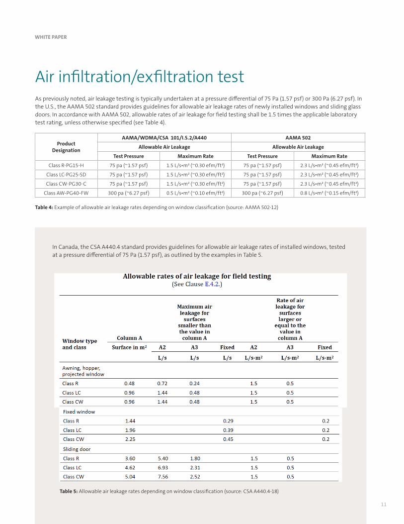
Air infiltration/exfiltration testAs previously noted, air leakage testing is typically undertaken at a pressure differential of 75 Pa (1.57 psf) or 300 Pa (6.27 psf). In the U.S., the AAMA 502 standard provides guidelines for allowable air leakage rates of newly installed windows and sliding glass doors. In accordance with AAMA 502, allowable rates of air leakage for field testing shall be 1.5 times the applicable laboratory test rating, unless otherwise specified (see Table 4).
In Canada, the CSA A440.4 standard provides guidelines for allowable air leakage rates of installed windows, tested at a pressure differential of 75 Pa (1.57 psf), as outlined by the examples in Table 5.
Table 4: Example of allowable air leakage rates depending on window classification (source: AAMA 502-12)
Table 5: Allowable air leakage rates depending on window classification (source: CSA A440.4-18)

WHITE PAPER
12
When it comes to metal and glass curtain walls, the allowable air leakage rates are typically indicated in the architectural specifications and will vary depending on local building and energy codes as well as for fixed and operable wall sections. The field air leakage resistance test consists of installing and sealing a chamber to cover the interior or exterior face of the specimen to be tested. Air is then supplied to or exhausted from the chamber at the rate required to maintain the specified test pressure difference across the specimen. The resulting air flow through the test specimen is then measured.
Figure 25: Typical setup for field air leakage resistance test (source: CSA A440.4)
Figure 26: Portable smoke generator used to fill test chamber with white smoke
Figure 27: Excessive smoke exfiltration visible on exterior side of curtain wall test specimen
It is important to note that it is often difficult to obtain accurate air leakage results in the field, particularly with curtain wall assemblies. Therefore, test results should be questioned when extraneous air leakage from either the test chamber and/or the confines of the test specimen significantly exceeds the allowable air leakage for the test specimen.
In cases in which it is not practical or possible to quantify air leakage, smoke exfiltration testing can serve as an effective alternative method. The smoke exfiltration test is undertaken by applying a uniform positive static pressure differential of 75 Pa (1.57 psf) across the test specimen then filling the test chamber with white smoke generated by a portable smoke generator. It is then possible to check for any visible excessive smoke exfiltration from the exterior side of the test specimen.

Figure 28: Typical setup for field air leakage resistance test (source: CSA A440.4)
WHITE PAPER
13
Figure 29: Calibrated sprinkler rack hung from suspended scaffolding
Figure 30: Calibrated sprinkler rack hung from a motorized man lift
Figure 31: Portable water reservoir and pump system
Figure 32: Temporary exterior heating via test specimen
Water penetration testThe field water penetration resistance test consists of attaching and sealing a chamber to the interior or exterior face of the test specimen to be tested by supplying or exhausting air to the chamber at the rate required to maintain the desired air pressure difference across the test specimen. At the same time, water is applied to the exterior face of the test specimen at the required rate (5 gal US/h/ft²) while observing for any water penetration in the interior.
In the U.S., the AAMA 502 standard provides guidelines for allowable water penetration resistance ratings of newly installed fenestration products, while the AAMA 503 standard provides guidelines for allowable water penetration resistance ratings of newly installed storefronts, curtain walls and sloped glazing systems. In accordance with these standards, water penetration resistance tests are conducted at a static test pressure equal to two-thirds of the applicable laboratory test rating, unless otherwise specified. In Canada, there is no provision in the CSA A440.4 standard for reduction in field testing pressure.
For the water penetration resistance field test, a calibrated sprinkler rack is hung on the exterior side of the test specimen so that a continuous and uniform water spray can be applied. Sufficient water pressure must be available on-site in order to ensure that the required amount of water is sprayed on the entire specimen. When available water pressure is not sufficient, the use of a portable water reservoir and pump system may be necessary.
It is also important that the exterior temperatures be above freezing in order to run a water test. When undertaking a water test in winter conditions, a temporary heated enclosure should be installed on the exterior side of the test specimen.

WHITE PAPER
14
Other diagnostic toolsDepending on the specifics of an intended window or curtain wall application, a variety of other diagnostic tools can be used to assess the performance of the vertical building envelope, either as a quality control measure or for forensic purposes. For example, when attempting to pinpoint a specific water infiltration problem, the methods detailed in AAMA 501.2, quality assurance and diagnostic water leakage field check of installed storefronts, curtain walls, and sloped glazing systems, can be used.
Infrared thermography is also used extensively in the building construction industry as a quality control and forensic tool to assess air leakage performance and the presence of moisture in exterior wall assemblies. Such analysis is usually conducted in accordance with the methods detailed in CAN/CGSB 149-GP-2MP, manual for thermographic analysis of building enclosures.
Figure 33: Diagnostic hose testing of curtain wall section
Figure 35: Thermographic image of excessive air leakage at the interface of the curtain wall with the adjacent wall assembly
Figure 34: Diagnostic hose testing window/wall interface
Figures 36 and 37: Thermographic image of excessive air leakage at the perimeter of the fenestration system

15
WHITE PAPER
Summary + Conclusion
Today, major building projects require specialized attention to the quality and integrity of windows and curtain wall structures and components, both during and after construction. The testing of these critical building elements to evaluate their performance under the range of anticipated exposure scenarios is essential, not only to help ensure the safety and comfort of building occupants but also to reduce the potential for premature repairs and renovations that can adversely impact a building’s return to investors and shareholders.
For more than 30 years, UL CLEB, a UL company, has served as a recognized leader in the building sciences, with specialized expertise in building envelope technologies and systems. With offices and testing facilities located throughout North America, we offer developers, contractors and investors a full range of services, including advisory, testing, quality control, forensics and commissioning. Our team of architects, engineers, technologists and building specialists can provide design assistance, laboratory and on-site testing of critical building envelope components and ongoing quality assessment services. Our experts also work with building standards associations and government officials to help ensure that applicable standards and requirements remain relevant to new and emerging building envelope technology developments.
For more information about our services, contact [email protected] or visit us at UL.com/buildingenvelope.

References
Canada Mortgage and Housing Corporation, ‘‘Best Practice Guide - Glass and Metal Curtain Walls,’’ 2004.
Quirouette, R.L., ‘‘Building Envelope Design using Metal and Glass Curtain Wall Systems,’’ Building Practice Note, Division of Building Research, National Research Council Canada, September 1982.
Gonçalves, M., Gendron, P., Colantionio, T., ‘‘Commissioning of Exterior Building Envelopes of Large Buildings for Air Leakage and Resultant Moisture Accumulation using Infrared Thermography and Other Diagnostic Tools,’’ Thermal Solutions 2007, Sarasota, Florida.
WHITE PAPER
16
UL and the UL logo are trademarks of UL LLC © 2018. All rights reserved. This white paper may not be copied or distributed without permission. It is provided for general information purposes only and is not intended to convey legal or other professional advice.