Embed Size (px)
Citation preview
Evaluating Overheads of Multi-bit Soft Error
Protection Techniques at Hardware Level Sponsored by SRC and Freescale under SRC task number 2042
Lukasz G. Szafaryn, Kevin Skadron Department of Computer Science University of Virginia Brett H. Meyer Department of Electrical & Computer Engineering McGill University
SRC Task: 2042
2
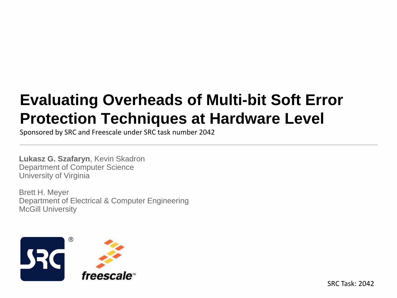
Problem: Multi-bit Soft Errors
• As devices become smaller, particle strike radius affects more circuit
components
• In addition to storage (SRAM) circuits, it is now becoming a concern
for logic (combinational/sequential) components
• Single particle strike can cause a multi-bit soft error that affects bits in
the same or adjacent component(s)
Area covered by a 2um particle strike radius with respect to the
area of two 3-bit registers at various technology nodes [1]
3
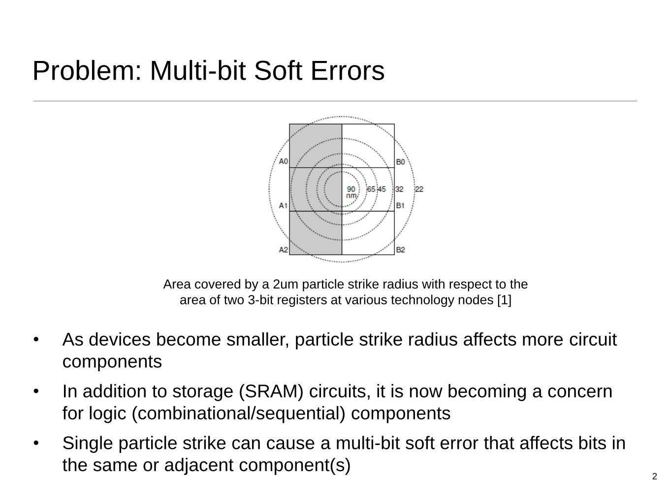
Motivation
• Traditional techniques for
single-bit soft errors in logic
do not offer adequate
protection against multi-bit
errors
• We need to evaluate more
aggressive techniques as
they significantly change
the overhead of protection
• We evaluate: • EDC/ECC (SECDED)
• Residue Codes
• Spatial Redundancy
• Temporal Redundancy
Single-bit Upset Multi-bit Upset
(Interleaved) Parity
Feature Upsizing
EDC/ECC and Residue Codes (ALU/FPU)
Spatial and Temporal Redundancy
1 0
1 0 1
0

4
Implementation
• Use example processor design • OpenRISC 1200 core
• Area-proportional ALU/FPU (20%) and
Cache (40%)
• Synthesized with IBM 90nm technology
• Develop considered protection
techniques and apply them • In combinations for different types of
components
• At granularities: pipeline-stage, FE/BE or core
• Evaluate protection scenarios in
terms of • Area
• Delay
• Average Power 90nm technology
5
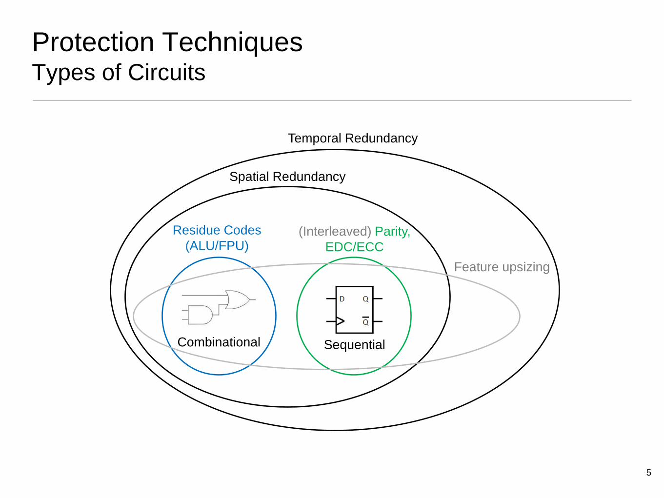
Protection Techniques Types of Circuits
Combinational Sequential
Residue Codes
(ALU/FPU) (Interleaved) Parity,
EDC/ECC
Spatial Redundancy
Temporal Redundancy
Feature upsizing
6
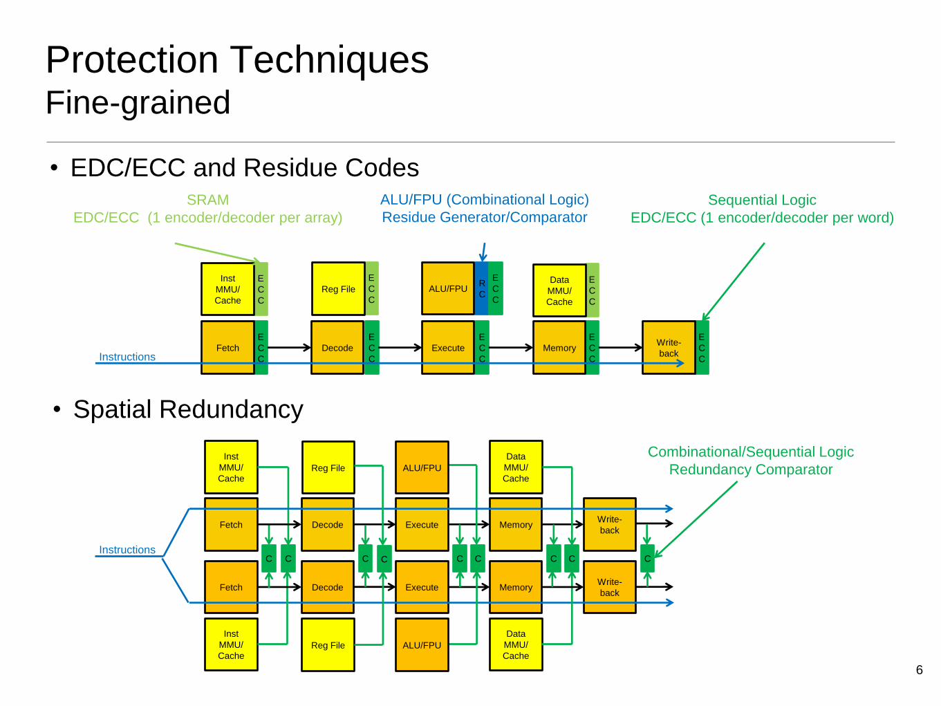
Protection Techniques Fine-grained
SRAM
EDC/ECC (1 encoder/decoder per array)
E
C
C
E
C
C
E
C
C
E
C
C
E
C
C
E
C
C
E
C
C
E
C
C
R
C
Fetch Decode Execute Memory Write-
back
Inst
MMU/
Cache
Data
MMU/
Cache
Reg File ALU/FPU
ALU/FPU (Combinational Logic)
Residue Generator/Comparator
Sequential Logic
EDC/ECC (1 encoder/decoder per word)
E
C
C
Fetch Decode Execute Memory Write-
back
Inst
MMU/
Cache
Data
MMU/
Cache Reg File
C
Fetch
C C C C C C C
Decode Execute Memory Write-
back
Inst
MMU/
Cache Reg File
Data
MMU/
Cache ALU/FPU
ALU/FPU
C Instructions
Instructions
Combinational/Sequential Logic
Redundancy Comparator
• EDC/ECC and Residue Codes
• Spatial Redundancy
7
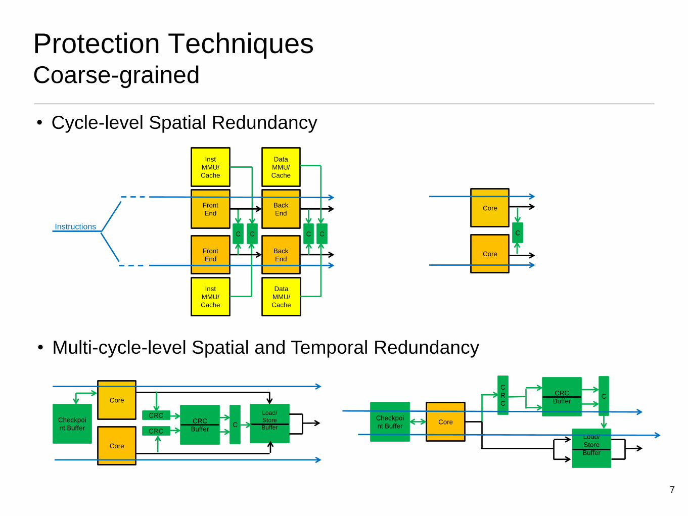
Protection Techniques Coarse-grained
Front
End
Back
End
Inst
MMU/
Cache
Data
MMU/
Cache
C
Front
End
C C C
Back
End
Inst
MMU/
Cache
Data
MMU/
Cache
Core
C
Core
Core
CRC
Core
Checkpoi
nt Buffer CRC
Buffer CRC
Instructions
Load/
Store
Buffer
C Core Checkpoi
nt Buffer
CRC
Buffer
Load/
Store
Buffer
C
C
R
C
• Cycle-level Spatial Redundancy
• Multi-cycle-level Spatial and Temporal Redundancy


10
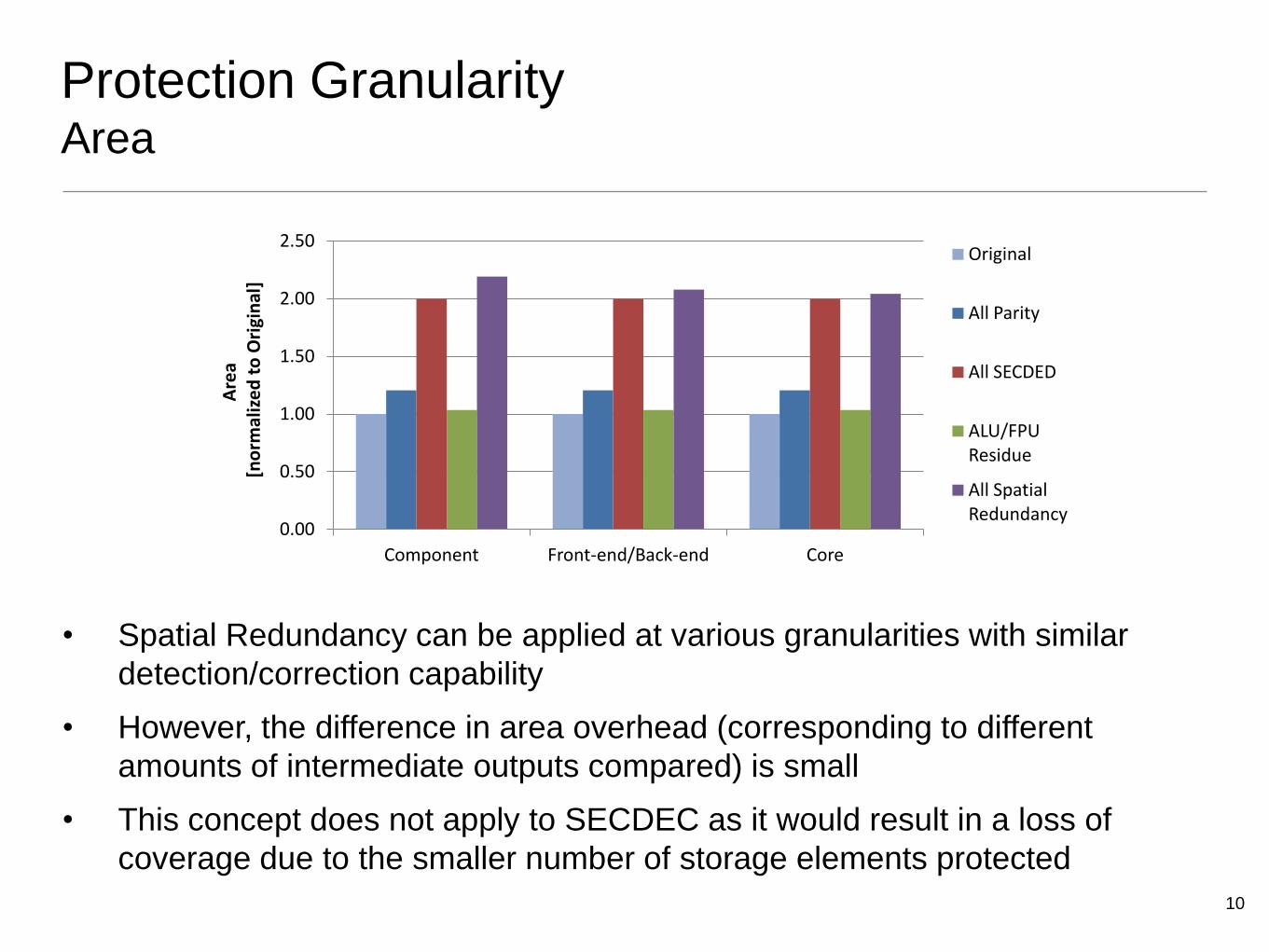
Protection Granularity Area
• Spatial Redundancy can be applied at various granularities with similar
detection/correction capability
• However, the difference in area overhead (corresponding to different
amounts of intermediate outputs compared) is small
• This concept does not apply to SECDEC as it would result in a loss of
coverage due to the smaller number of storage elements protected
0.00
0.50
1.00
1.50
2.00
2.50
Component Front-end/Back-end Core
Are
a [
no
rmal
ize
d t
o O
rigi
nal
] Original
All Parity
All SECDED
ALU/FPU Residue
All Spatial Redundancy
11
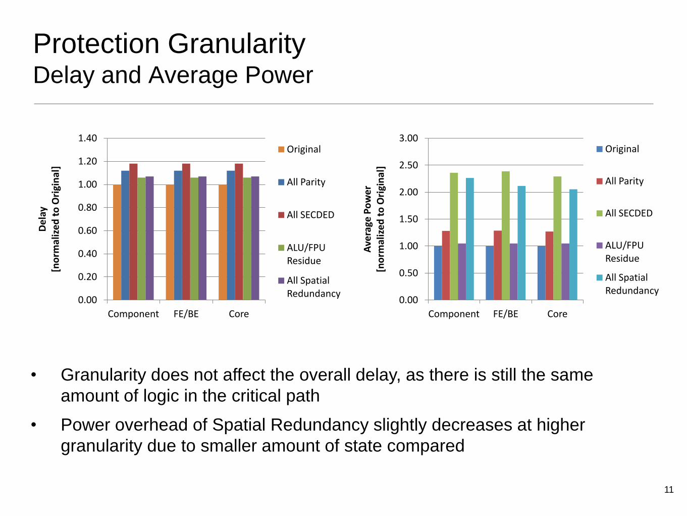
Protection Granularity Delay and Average Power
• Granularity does not affect the overall delay, as there is still the same
amount of logic in the critical path
• Power overhead of Spatial Redundancy slightly decreases at higher
granularity due to smaller amount of state compared
0.00
0.20
0.40
0.60
0.80
1.00
1.20
1.40
Component FE/BE Core
De
lay
[no
rmal
ize
d t
o O
rigi
nal
]
Original
All Parity
All SECDED
ALU/FPU Residue
All Spatial Redundancy
0.00
0.50
1.00
1.50
2.00
2.50
3.00
Component FE/BE Core
Ave
rage
Po
we
r [n
orm
aliz
ed
to
Ori
gin
al]
Original
All Parity
All SECDED
ALU/FPU Residue
All Spatial Redundancy
12
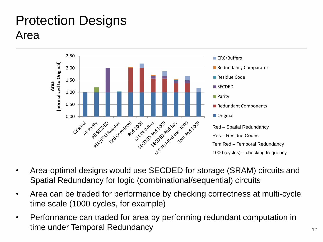
Protection Designs Area
• Area-optimal designs would use SECDED for storage (SRAM) circuits and
Spatial Redundancy for logic (combinational/sequential) circuits
• Area can be traded for performance by checking correctness at multi-cycle
time scale (1000 cycles, for example)
• Performance can traded for area by performing redundant computation in
time under Temporal Redundancy
0.00
0.50
1.00
1.50
2.00
2.50 A
rea
[no
rmal
ize
d t
o O
rigi
nal
] CRC/Buffers
Redundancy Comparator
Residue Code
SECDED
Parity
Redundant Components
Original
Red – Spatial Redundancy
Res – Residue Codes
Tem Red – Temporal Redundancy
1000 (cycles) – checking frequency
13
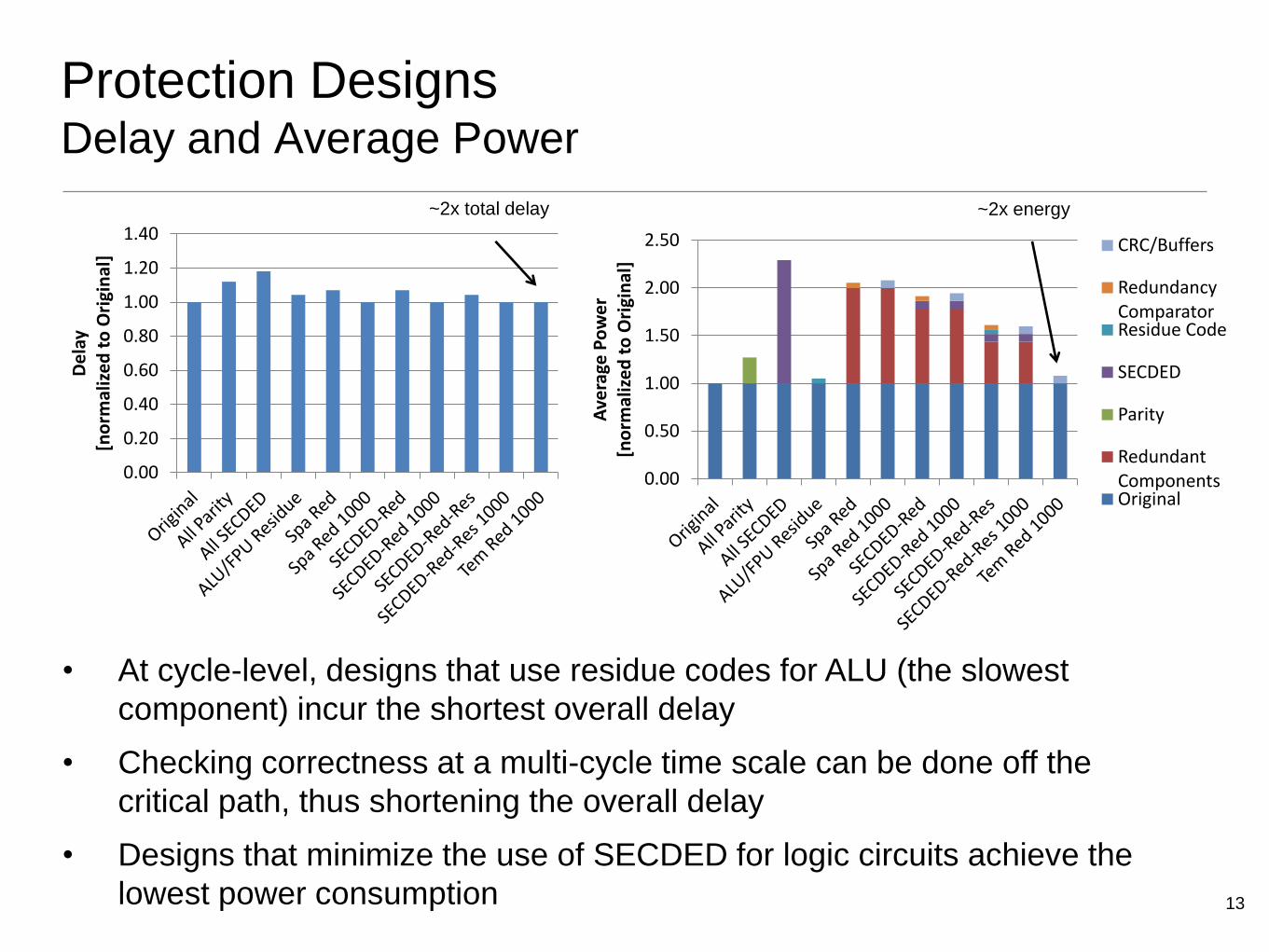
Protection Designs Delay and Average Power
• At cycle-level, designs that use residue codes for ALU (the slowest
component) incur the shortest overall delay
• Checking correctness at a multi-cycle time scale can be done off the
critical path, thus shortening the overall delay
• Designs that minimize the use of SECDED for logic circuits achieve the
lowest power consumption
0.00
0.50
1.00
1.50
2.00
2.50
Ave
rage
Po
we
r [n
orm
aliz
ed
to
Ori
gin
al]
CRC/Buffers
Redundancy Comparator Residue Code
SECDED
Parity
Redundant Components Original
0.00
0.20
0.40
0.60
0.80
1.00
1.20
1.40
De
lay
[no
rmal
ize
d t
o O
rigi
nal
]
~2x energy ~2x total delay
14
Conclusions
• Multi-bit soft errors are becoming a concern in logic
(combinational/sequential) circuits
• Protection against multi-bit errors in logic components requires
techniques that are more aggressive than traditionally used parity
• Error detecting/correcting codes are preferred for storage (SRAM)
circuits while Spatial Redundancy is preferred for logic
(combinational/sequential) circuits
• Increased granularity of Spatial Redundancy only slightly reduces
overhead of protection
• Area can be traded for performance by checking correctness at
multi-cycle scale
• Performance can be traded for area by performing redundant
computation in time under Temporal Redundancy

15
Future Work
• Use error injection in the simulator to evaluate vulnerability of
components and effectiveness of protection techniques
• Evaluate performance and power for common benchmarks
• Investigate recovery overhead of protection mechanisms
• Consider wider range of protection techniques
• Evaluate benefit of multi-cycle-level Temporal Redundancy in a
superscalar processor at application level
16
Technology Transfer
• Industry Interactions • Freescale
• Internships • Intel, summer 2011-2012
• Publications/presentations • TECHCON 2012 paper

Questions
References
[1] Nishant J. George, Carl R. Elks, Barry W. Johnson, John Lach. “Bit-slice
logic interleaving for spatial multi-bit soft-error tolerance.”
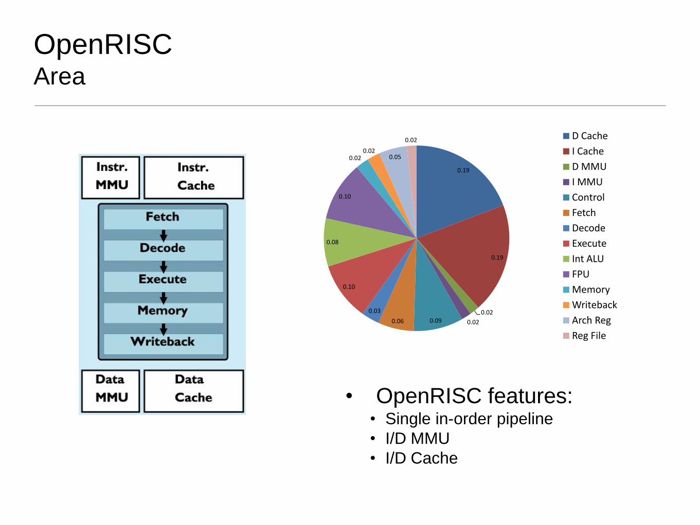
OpenRISC Area
0.19
0.19
0.02
0.02 0.09 0.06
0.03
0.10
0.08
0.10
0.02 0.02
0.05
0.02 D Cache
I Cache
D MMU
I MMU
Control
Fetch
Decode
Execute
Int ALU
FPU
Memory
Writeback
Arch Reg
Reg File
• OpenRISC features: • Single in-order pipeline
• I/D MMU
• I/D Cache
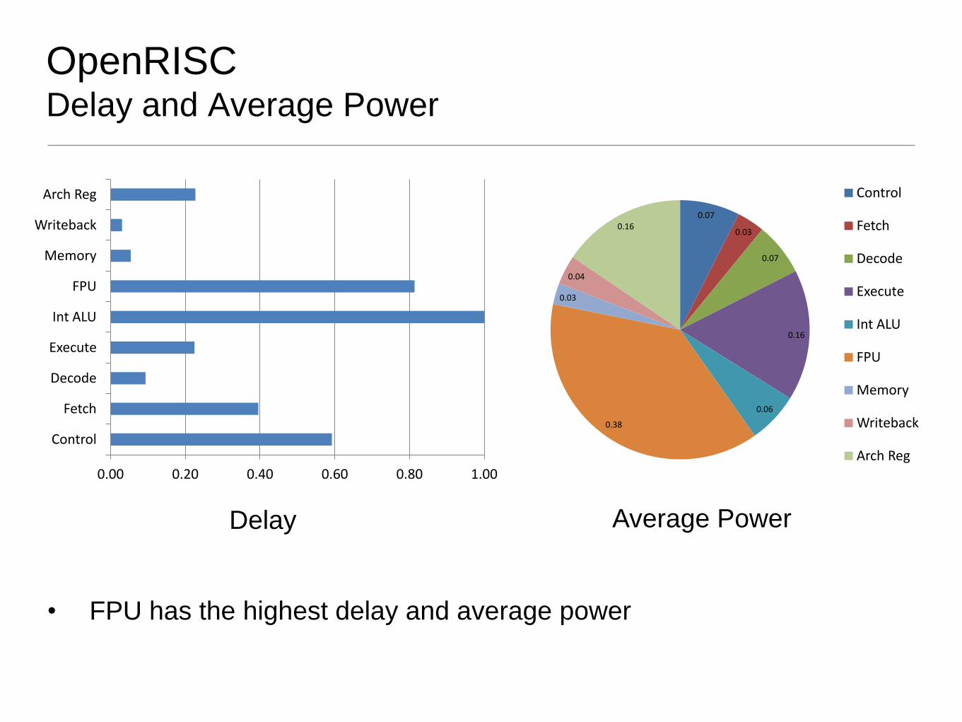
OpenRISC Delay and Average Power
0.07
0.03
0.07
0.16
0.06
0.38
0.03
0.04
0.16
Control
Fetch
Decode
Execute
Int ALU
FPU
Memory
Writeback
Arch Reg 0.00 0.20 0.40 0.60 0.80 1.00
Control
Fetch
Decode
Execute
Int ALU
FPU
Memory
Writeback
Arch Reg
• FPU has the highest delay and average power
Delay Average Power
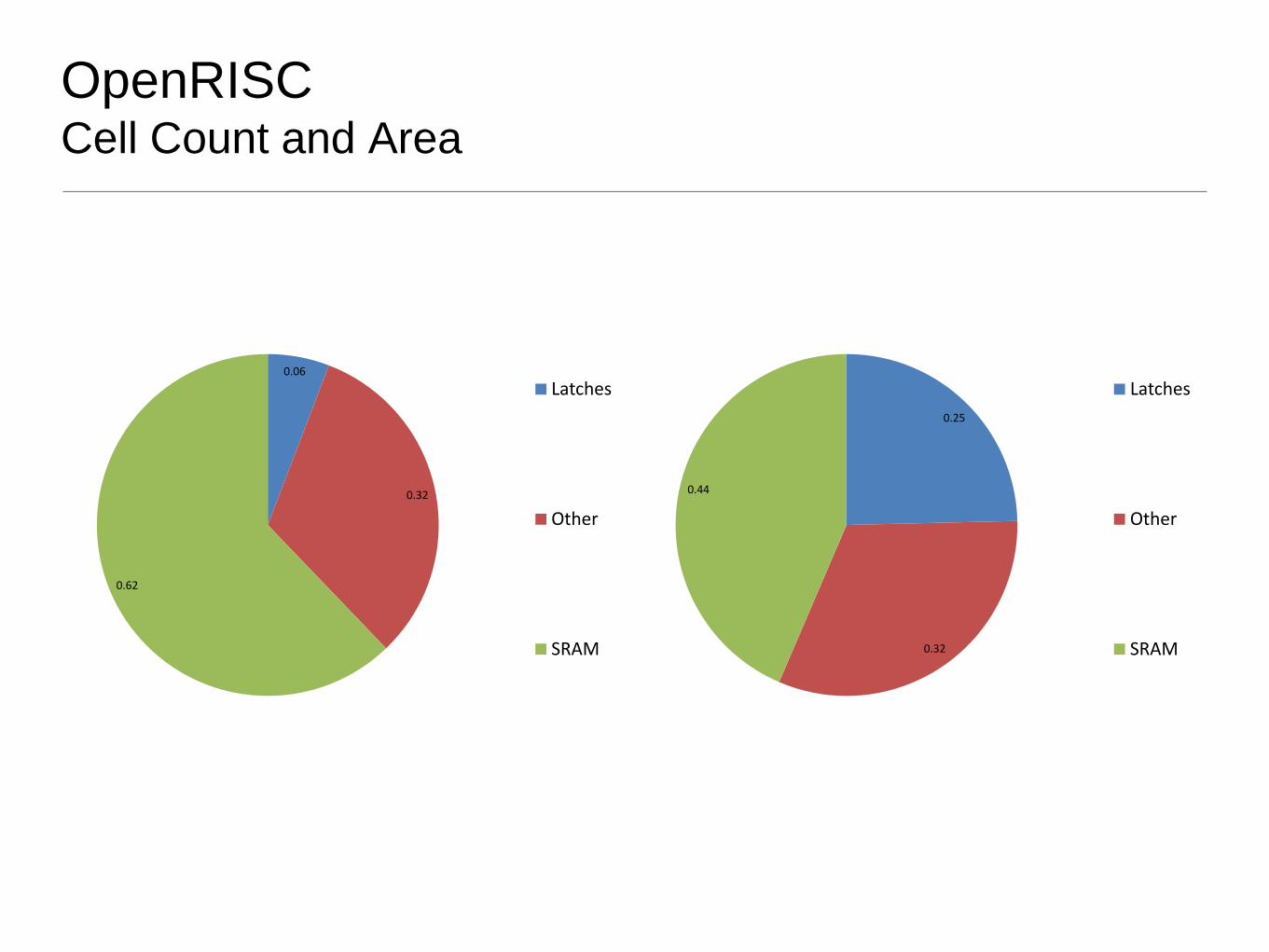
OpenRISC Cell Count and Area
0.06
0.32
0.62
Latches
Other
SRAM
0.25
0.32
0.44
Latches
Other
SRAM


![chapter 3 overheads - John D. Cresslercressler.ece.gatech.edu/courses/COE_3002/overheads/F19/chapter 3... · Title: Microsoft PowerPoint - chapter 3 overheads [Compatibility Mode]](https://img.pdfslide.us/doc/110x75/5fb70f40766c616ca64667e8/chapter-3-overheads-john-d-3-title-microsoft-powerpoint-chapter-3-overheads.jpg)