Embed Size (px)
Citation preview

Dimičeva 12
1000 Ljubljana, Slovenija
Tel.: +386 (0)1-280 44 72, 280 45 37 Fax: +386 (0)1-280 44 84 E-pošta: [email protected] http://www.zag.si/ts
član EOTA Member of EOTA
European Technical Assessment ETA-10/0423 of 26.08.2014 English version prepared by ZAG
I GENERAL PART Komercialno ime Trade name
ATS evo
Imetnik tehnične ocene Holder of Technical Assessment
FRIULSIDER S.p.A. via Trieste 1 33048 San Giovanni al Natisone (UD) Italy
Družina proizvoda Torzijsko kontrolirano zatezno kovinsko sidro iz galvansko pocinkanega jekla velikosti M6, M8, M10, M12 in M16 za vgradnjo v beton
Product family Torque controlled expansion anchor made of galvanised steel of sizes M6, M8, M10, M12 and M16 for use in concrete
Proizvodni obrat Manufacturing plant
FRIULSIDER S.p.A. via Trieste 1 33048 San Giovanni al Natisone (UD) Italy
Ta Evropska tehnična ocena vsebuje
This European Technical Assessment contains
14 strani vključno s 11 prilogami, ki so sestavni del te ocene
14 pages including 11 annexes, which form an integral part of the document
Ta Evropska tehnična ocena je izdana na podlagi Uredbe (EU) št. 305/2001 na osnovi
This European Technical Assessment is issued in according to Regulation (EU) No 305/2011, on the basis of
Smernice za evropska tehnična soglasja ETAG 001 – del 1 in 2, izdaja 2013, ki se uporablja kot EAD
Guideline for European Technical Approval ETAG 001 – part 1 and 2, edition 2013, used as EAD
Ta ocena zamenjuje This Assessment replaces
ETA-10/0423 izdano dne 06.06.2014 ETA-10/0423 issued on 06.06.2014
Translations of this European Technical Assessment in other languages shall fully correspond to the original issued document and should be identified as such.
Communication of this European Technical Assessment, including transmission by electronic means, shall be in full (excepted the confidential Annex(es) referred to above). However, partial reproduction may be made, with the written consent of the issuing Technical Assessment Body. Any partial reproduction has to be identified as such.
Page 2 of ETA-10/0423, issued on 26.08.2014, English version prepared by ZAG Ljubljana
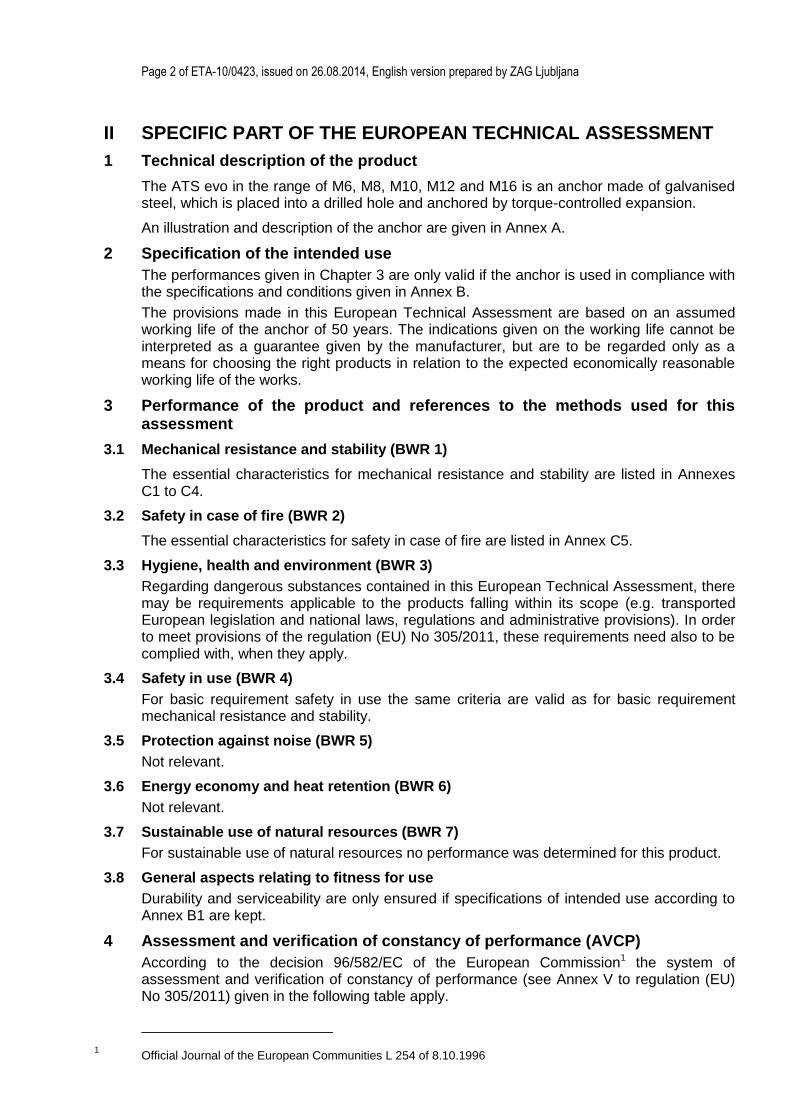
II SPECIFIC PART OF THE EUROPEAN TECHNICAL ASSESSMENT
1 Technical description of the product
The ATS evo in the range of M6, M8, M10, M12 and M16 is an anchor made of galvanised steel, which is placed into a drilled hole and anchored by torque-controlled expansion.
An illustration and description of the anchor are given in Annex A.
2 Specification of the intended use
The performances given in Chapter 3 are only valid if the anchor is used in compliance with the specifications and conditions given in Annex B.
The provisions made in this European Technical Assessment are based on an assumed working life of the anchor of 50 years. The indications given on the working life cannot be interpreted as a guarantee given by the manufacturer, but are to be regarded only as a means for choosing the right products in relation to the expected economically reasonable working life of the works.
3 Performance of the product and references to the methods used for this assessment
3.1 Mechanical resistance and stability (BWR 1)
The essential characteristics for mechanical resistance and stability are listed in Annexes C1 to C4.
3.2 Safety in case of fire (BWR 2)
The essential characteristics for safety in case of fire are listed in Annex C5.
3.3 Hygiene, health and environment (BWR 3)
Regarding dangerous substances contained in this European Technical Assessment, there may be requirements applicable to the products falling within its scope (e.g. transported European legislation and national laws, regulations and administrative provisions). In order to meet provisions of the regulation (EU) No 305/2011, these requirements need also to be complied with, when they apply.
3.4 Safety in use (BWR 4)
For basic requirement safety in use the same criteria are valid as for basic requirement mechanical resistance and stability.
3.5 Protection against noise (BWR 5)
Not relevant.
3.6 Energy economy and heat retention (BWR 6)
Not relevant.
3.7 Sustainable use of natural resources (BWR 7)
For sustainable use of natural resources no performance was determined for this product.
3.8 General aspects relating to fitness for use
Durability and serviceability are only ensured if specifications of intended use according to Annex B1 are kept.
4 Assessment and verification of constancy of performance (AVCP)
According to the decision 96/582/EC of the European Commission1 the system of assessment and verification of constancy of performance (see Annex V to regulation (EU) No 305/2011) given in the following table apply.
1 Official Journal of the European Communities L 254 of 8.10.1996

Page 3 of ETA-10/0423, issued on 26.08.2014, English version prepared by ZAG Ljubljana
Product Intended use Level of class
System
Metal anchors for use in concrete
For fixing and/or supporting to concrete, structural elements (which contributes to the stability of the works) or heavy units
- 1
5 Technical details necessary for the implementation of the AVCP system
5.1 Tasks for the manufacturer
The manufacturer shall exercise permanent internal control of production of concerned product. All the elements, requirements and provisions adopted by the manufacturer shall be documented in a systematic manner in the form of written policies and procedures, including records of results performed. This production control system shall ensure that the product is in conformity with this European Technical Assessment.
The manufacturer may only use raw materials stated in the technical documentation of this European Technical Assessment.
The factory production control shall be in accordance with the Control plan which is a part of the technical documentation of this European Technical Assessment. The Control plan2 is laid down in the context of the factory production control system operated by the manufacturer and deposited at Slovenian National Building and Civil Engineering Institute (ZAG Ljubljana). The results of factory production Control shall be recorded and evaluated in accordance with the provisions of the control plan.
The manufacturer shall, on the basis of a contract, involve a body, which is notified for the tasks referred to in a section 4 in the field of anchors in order to undertake the actions laid down in section 5.2. For this purpose the Control plan referred to in sections 5.1 and 5.2 shall be handed over by the manufacturer to the notified body involved.
The manufacturer shall make a Declaration of performance, stating that the construction product is in conformity with the provisions of this European Technical Assessment.
5.2 Tasks for the notified bodies
The notified body shall retain the essential points of its actions defined in Annex V of Regulation (EU) No. 305/2011 for system 1 and state results obtained and conclusions drawn in a written report.
The notified certification body involved by the manufacturer shall issue an EC certificate of constancy of performance the product stating the conformity with the provisions of this European Technical Assessment.
In cases where the provisions of the European Technical Assessment and its Control plan are no longer fulfilled the notified body shall withdraw the certificate of constancy of performance and inform the Slovenian National Building and Civil Engineering Institute (ZAG Ljubljana) without delay.
Issued in Ljubljana on 26.08.2014
Signed by:
Franc Capuder, M.Sc., Research Engineer
Head of Service of TAB
2 The Control plan is a confidential part of the technical documentation of this European Technical Assessment,
but not published together with the ETA, and handed over only to the notified body or bodies involved in the procedure of attestation of conformity.

Page 4 of ETA-10/0423, issued on 26.08.2014, English version prepared by ZAG Ljubljana
Type S with screw
(SH)
Type B with threaded bar Type SK with countersunk screw Sleeve for M16 size
ATS evo
Annex A1 Product description Product and intended use
L = length of the anchor (mm)
tfix = thickness of fixture (mm)
d0 = nominal drill hole diameter (mm)
hnom = minimum installation depth (mm)
hef = effective anchorage depth (mm)
df = diameter of clearance hole in the fixture (mm)
h1 = depth of drill hole (mm)
hmin = minimum thickness of the concrete member (mm)
Tinst = torque moment (Nm)
Marking: Identification mark of the producer - trade name of the anchor
nominal drill hole diameter / max thickness of fixture (and line for minimum embedment and max thickness of fixture) e.g.: FM-ATS Ø15/20

Page 5 of ETA-10/0423, issued on 26.08.2014, English version prepared by ZAG Ljubljana
ATS evo-S
(type SH)
1 2 3 4 5 6 (6)
ATS evo-B
7 8
ATS evo-SK
9
1 Cone 2 Expansion sleeve 3 Plastic sleeve 4 Distance sleeve 5 Washer 6 Hexagonal screw 7 Hexagonal nut 8 Threaded bar 9 Countersunk screw
ATS evo
Annex A2 Product description Product and components

Page 6 of ETA-10/0423, issued on 26.08.2014, English version prepared by ZAG Ljubljana
Table A1: Materials
Part of anchor Material
1 Cone hardened steel EN 10087 1)
2 Expansion sleeve M6÷M12 hardened steel EN 101321) - M16 steel EN 100871)
3 Plastic sleeve Pa6 ISO 1874/1
4 Distance sleeve Steel EN 100251)
5 Washer Steel EN 101391)
6 Hexagon screw Steel grade 8.8 EN ISO 898/11) (DIN 931 -DIN 933 - type SH=head large)
7 Hexagonal nut Steel grade 8 DIN 9341) (EN ISO 898/2)
8 Threaded bar Steel grade 8.8 EN ISO 898/11)
9 Countersunk screw Steel grade 8.8 EN ISO 898/11)
1) zinc plated 5µm according to EN ISO 4042
ATS evo
Annex A3 Product description Materials

Page 7 of ETA-10/0423, issued on 26.08.2014, English version prepared by ZAG Ljubljana
Specifications of intended use
Anchorages subjected to:
Static, quasi static, seismic load and fire.
Base materials:
Cracked and non-cracked concrete.
Reinforced and unreinforced normal weight concrete of strength class C20/25 at minimum and C50/60 at maximum according to EN 206-1:2000/A2:2005.
Use conditions (Environmental conditions):
Structures subjected to dry internal conditions.
Design:
Anchorages are designed under the responsibility of an engineer experienced in anchorages and concrete work.
Anchorages under static and quasi-static actions are designed in accordance with ETAG 001, Annex C, design method A, Edition August 2010 or CEN/TS 1992-4.
For seismic application the anchorages are designed in accordance with TR 045 “Design of metal anchors for use in concrete under seismic actions”.
For application with resistance under fire exposure the anchorages are designed in accordance with method given in TR 020 “Evaluation of anchorage in concrete concerning resistance to fire”.
Verifiable calculation notes and drawings are prepared taking into account of the load to be anchored. The position of the anchor is indicated on the design drawings (e.g. position of the anchor relative to reinforcement or to supports, etc.).
Installation:
Anchor installation carried out by appropriately qualified personnel and under supervision of the person responsible for technical matters of the site.
Use of the anchor only supplied by the manufacturer without exchanging the components of an anchor.
Anchor installation in accordance with the manufacturer’s specification and drawings and using the appropriate tools.
Checks before placing the anchor to ensure that the strength class of the concrete in which the anchor is to be placed is in the rang given and is not lower that of the concrete to which the characteristic loads apply for.
Check of concrete being well compacted, e.g. without significant voids.
Effective anchorage depth, edge distances and spacing not less than the specified values without minus tolerances.
Hole drilling by hammer drill.
Cleaning of the hole of drilling dust.
Positioning of the drill holes without damaging the reinforcement.
Application of specified torque moment using a calibrated torque wrench.
In case of aborted hole, drilling of new hole at a minimum distance of twice the depth of the aborted hole, or smaller distance provided the aborted drill hole is filled with high strength mortar and no shear or oblique tension loads in the direction of aborted hole.
ATS evo
Annex B1 Intended use Specification

Page 8 of ETA-10/0423, issued on 26.08.2014, English version prepared by ZAG Ljubljana
Table B1: Dimensions
Anchor size M6 M8 M10 M12 M16
Nominal diameter of anchor dnom [mm] 10 12 15 18 24
Minimum installation depth hnom ≥ [mm] 60 70 80 100 115
Length of the anchor L [mm] tfix + 60 tfix + 70 tfix + 80 tfix + 100 tfix + 115
Thickness of the fixture
Type S (SH) /B tfix,min [mm] 0 0 0 0 0
Type SK tfix,min [mm] 5 6 7 8 -
Type S (SH)/B/SK tfix,max [mm] 200 250 300 350 400
Nominal diameter of the head of the countersunk screw Type SK dsk [mm]
17 21 26 31 -
ATS evo
Annex B2 Intended use Dimensions of the anchors

Page 9 of ETA-10/0423, issued on 26.08.2014, English version prepared by ZAG Ljubljana
Table B2: Installation data
Anchor size M6 M8 M10 M12 M16
Nominal drill hole diameter d0 [mm] 10 12 15 18 24
Cutting diameter of drill bit dcut ≤ [mm] 10,45 12,50 15,50 18,50 24,55
Depth of drill hole h1 ≥ [mm] 75 85 95 115 130
Minimum installation depth hnom ≥ [mm] 60 70 80 100 115
Effective anchorage depth hef [mm] 49 59 67 88 99
Diameter of clearance hole in the fixture df ≤ [mm] 12 14 17 20 26
Length of the anchor L [mm] tfix + 60 tfix + 70 tfix + 80 tfix + 100 tfix + 115
Torque moment Tinst [Nm] 10 20 45 80 150
Table B3: Minimum thickness of concrete member spacing, and edge distances
Anchor size M6 M8 M10 M12 M16
Minimum thickness of the concrete member hmin mm 100 120 140 180 200
Minimum spacing smin mm 50 60 70 80 100
for c mm 75 90 100 150 200
Minimum edge distance cmin mm 50 60 70 80 100
for s mm 75 90 100 150 200
ATS evo
Annex B3 Intended use Installation parameters
Page 10 of ETA-10/0423, issued on 26.08.2014, English version prepared by ZAG Ljubljana
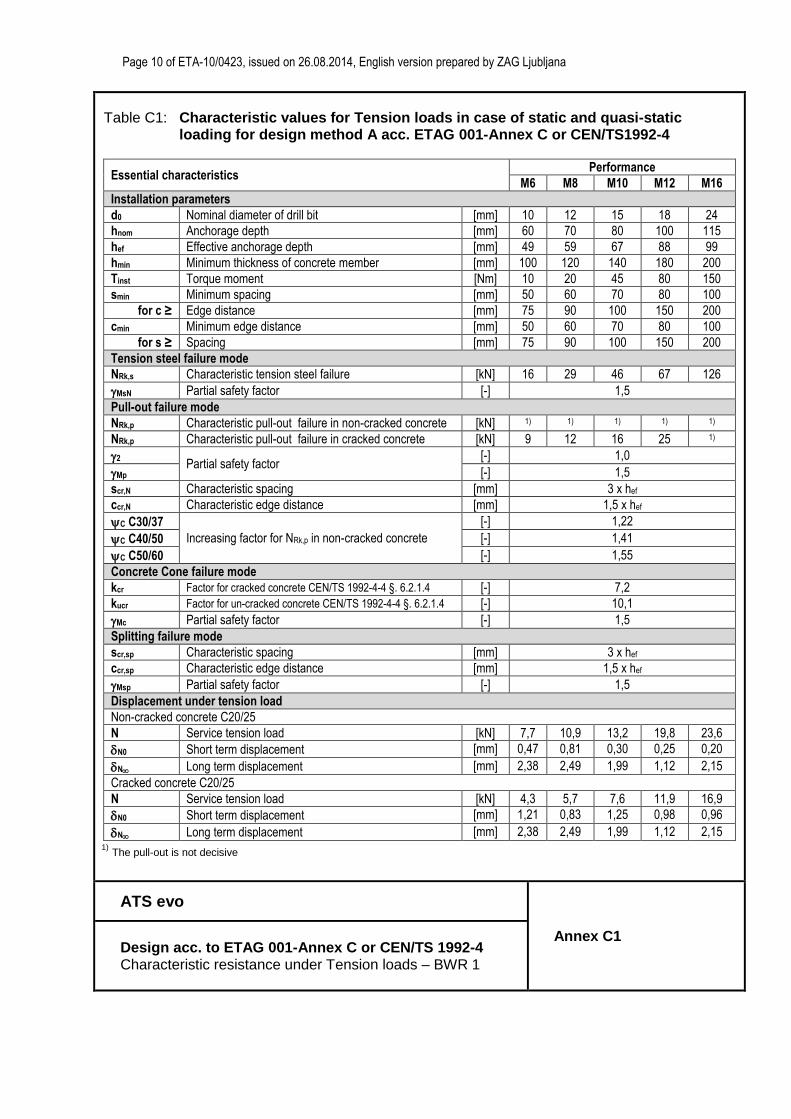
Table C1: Characteristic values for Tension loads in case of static and quasi-static loading for design method A acc. ETAG 001-Annex C or CEN/TS1992-4
Essential characteristics Performance
M6 M8 M10 M12 M16
Installation parameters
d0 Nominal diameter of drill bit [mm] 10 12 15 18 24
hnom Anchorage depth [mm] 60 70 80 100 115
hef Effective anchorage depth [mm] 49 59 67 88 99
hmin Minimum thickness of concrete member [mm] 100 120 140 180 200
Tinst Torque moment [Nm] 10 20 45 80 150
smin Minimum spacing [mm] 50 60 70 80 100
for c ≥ Edge distance [mm] 75 90 100 150 200
cmin Minimum edge distance [mm] 50 60 70 80 100
for s ≥ Spacing [mm] 75 90 100 150 200
Tension steel failure mode
NRk,s Characteristic tension steel failure [kN] 16 29 46 67 126
MsN Partial safety factor [-] 1,5
Pull-out failure mode
NRk,p Characteristic pull-out failure in non-cracked concrete [kN] 1) 1) 1) 1) 1)
NRk,p Characteristic pull-out failure in cracked concrete [kN] 9 12 16 25 1)
2 Partial safety factor
[-] 1,0
Mp [-] 1,5
scr,N Characteristic spacing [mm] 3 x hef
ccr,N Characteristic edge distance [mm] 1,5 x hef
C C30/37
Increasing factor for NRk,p in non-cracked concrete
[-] 1,22
C C40/50 [-] 1,41
C C50/60 [-] 1,55
Concrete Cone failure mode
kcr Factor for cracked concrete CEN/TS 1992-4-4 §. 6.2.1.4 [-] 7,2
kucr Factor for un-cracked concrete CEN/TS 1992-4-4 §. 6.2.1.4 [-] 10,1
Mc Partial safety factor [-] 1,5
Splitting failure mode
scr,sp Characteristic spacing [mm] 3 x hef
ccr,sp Characteristic edge distance [mm] 1,5 x hef
Msp Partial safety factor [-] 1,5
Displacement under tension load
Non-cracked concrete C20/25
N Service tension load [kN] 7,7 10,9 13,2 19,8 23,6
N0 Short term displacement [mm] 0,47 0,81 0,30 0,25 0,20
N Long term displacement [mm] 2,38 2,49 1,99 1,12 2,15
Cracked concrete C20/25
N Service tension load [kN] 4,3 5,7 7,6 11,9 16,9
N0 Short term displacement [mm] 1,21 0,83 1,25 0,98 0,96
N Long term displacement [mm] 2,38 2,49 1,99 1,12 2,15 1)
The pull-out is not decisive
ATS evo
Annex C1 Design acc. to ETAG 001-Annex C or CEN/TS 1992-4 Characteristic resistance under Tension loads – BWR 1

Page 11 of ETA-10/0423, issued on 26.08.2014, English version prepared by ZAG Ljubljana
Table C2: Characteristic values for Shear loads in case of static and quasi-static loading for design method A acc. ETAG 001-Annex C or CEN/TS 1992-4
Essential characteristics Performance
M6 M8 M10 M12 M16
Shear steel failure
VRk,s Characteristic shear steel failure [kN] 14 26 42 50 97
M0Rk,s Bending moment characteristic failure [Nm] 12 30 60 105 266
MsV Partial safety factor [-] 1,25
Shear concrete pry-out and edge failure
k Factor in equation (5.6) of ETAG 001 Annex C § 5.2.3.3
[mm] 1,0 2,0
K3 Factor in equation (16) of CEN/TS 1992-4 § 6.2.2.3 [mm] 1,0 2,0
lef Effective anchorage depth [mm] 46 59 67 88 99
dnom Diameter of anchor [mm] 10 12 15 18 24
Mc Partial safety factor [-] 1,5
Displacement under shear load
V Service shear load [kN] 8,0 14,9 24,0 28,6 55,4
V0 Short term displacement [mm] 1,39 1,94 2,71 1,69 2,69
V Long term displacement [mm] 2,09 2,91 4,07 2,54 4,04
ATS evo
Annex C2 Design acc. to ETAG 001-Annex C or CEN/TS 1992-4 Characteristic resistance under Shear loads – BWR 1

Page 12 of ETA-10/0423, issued on 26.08.2014, English version prepared by ZAG Ljubljana
Table C3: Characteristic values for resistance in case of Seismic performance category C1 acc. TR045 “Design of Metal anchor under Seismic Actions”
Essential characteristics Performance
M6 M8 M10 M12 M16
Tension steel failure
NRk,s,seis C1 Characteristic tension steel failure [kN] 16 29 46 67 126
MsN,seis 2) Partial safety factor [-] 1,5
Pull-out failure mode NRk,p,seis = C × N0Rk,p,seis
NRk,p,seis C1 Characteristic pull-out failure in concrete C20/25
[kN] 6,8 12 16 25 35,51)
Mp,seis 2) Partial safety factor [-] 1,5
Shear steel failure
VRk,s,seisC1 Characteristic shear steel failure [kN] 9,8 13 20 20 48,5
MsV,seis 2) Partial safety factor [-] 1,25
1) The pull-out is not decisive 2) The recommended partial safety factors under seismic action (M,seis) are the same as for static loading
ATS evo
Annex C3 Design according to TR 045 Characteristic resistance under Seismic actions – BWR 1

Page 13 of ETA-10/0423, issued on 26.08.2014, English version prepared by ZAG Ljubljana
Table C4: Characteristic values for resistance in case of Seismic performance category C2 acc. TR045 “Design of Metal anchor under Seismic Actions”
Essential characteristics Performance
M6 M8 M10 M12 M16
Tension steel failure
NRk,s,seis C22) Characteristic tension steel failure [kN] - 29 46 67 126
MsN3) Partial safety factor [-] 1,5
Pull-out failure NRk,p,seis = C × N0Rk,seis
NRk,s,seis C22) Characteristic pull-out failure in concrete C20/25 [kN] - 3,9 7,8 15,3 28,8
MpN3) Partial safety factor [-] 1,5
N,sei(DSL)1)2) Displacement at DSL [mm] - 2,7 4,9 3,6 3,1
N,sei(USL)1)2) Displacement at USL [mm] - 12,8 15,2 14,0 11,5
Shear steel failure
VRk,s,seis C22) Characteristic shear failure [kN] - 10,2 17,0 17,0 43,9
MsV3) Partial safety factor [-] 1,25
V,sei(DSL)1)2) Displacement at DSL [mm] - 3,5 2,7 2,5 2,7
V,sei(USL)1)2) Displacement at USL [mm] - 6,8 6,3 5,8 6,1
1) The listed displacement represent mean values
2) A smaller displacement may be required in the design in the case of displacement sensitive fastenings or “rigid” supports. The characteristic resistance associated with such smaller displacement may be determined by linear interpolation or proportional reduction.
3) The recommended partial safety factors under seismic action (M,seis) are the same as for static loading
ATS evo
Annex C4 Design according to TR 045 Characteristic resistance under Seismic actions - BWR 1

Page 14 of ETA-10/0423, issued on 26.08.2014, English version prepared by ZAG Ljubljana
Table C5: Characteristic resistance under Fire exposure for design design acc. to TR020
Essential characteristics Performance
M6 M8 M10 M12 M16
Tension steel failure mode
FRk,s,fi,30 Duration = 30 minutes [kN] 0,20 0,37 0,87 1,69 3,14
FRk,s,fi,60 Duration = 60 minutes [kN] 0,18 0,33 0,75 1,26 2,36
FRk,s,fi,90 Duration = 90 minutes [kN] 0,14 0,26 0,58 1,10 2,04
FRk,s,fi,120 Duration = 120 minutes [kN] 0,10 0,18 0,46 0,84 1,57
Pull-out failure mode
FRk,p,fi,30 Duration = 30 minutes [kN] 2,25 3,00 4,00 6,25 8,88
FRk,p,fi,60 Duration = 60 minutes [kN] 2,25 3,00 4,00 6,25 8,88
FRk,p,fi,90 Duration = 90 minutes [kN] 2,25 3,00 4,00 6,25 8,88
FRk,p,fi,120 Duration = 120 minutes [kN] 1,80 2,40 3,20 5,00 7,10
Concrete cone failure mode
FRk,c,fi,30 Duration = 30 minutes [kN] 3,03 4,81 6,61 13,08 17,55
FRk,c,fi,60 Duration = 60 minutes [kN] 3,03 4,81 6,61 13,08 17,55
FRk,c,fi,90 Duration = 90 minutes [kN] 3,03 4,81 6,61 13,08 17,55
FRk,c,fi,120 Duration = 120 minutes [kN] 2,42 3,85 5,29 10,46 14,04
scr,N Characteristic spacing [mm] 4 x hef
ccr,N Characteristic edge distance [mm] 2 x hef
smin Minimum spacing [mm] 50 60 70 80 100
cmin Minimum edge distance [mm]
cmin = 2 hef; if fire attack from more than one side, the
edge distance of the anchor has to be
300mm and 2 hef
M,fi Partial safety factor [-] 1,01)
Shear steel failure without lever arm
VRk,s,fi,30 Duration = 30 minutes [kN] 0,20 0,37 0,87 1,69 3,14
VRk,s,fi,60 Duration = 60 minutes [kN] 0,18 0,33 0,75 1,26 2,36
VRk,s,fi,90 Duration = 90 minutes [kN] 0,14 0,26 0,58 1,10 2,04
VRk,s,fi,120 Duration = 120 minutes [kN] 0,10 0,18 0,46 0,84 1,57
Shear steel failure with lever arm
M0Rk,s,fi,30 Duration = 30 minutes [Nm] 0,15 0,37 1,12 2,62 6,66
M0Rk,s,fi,60 Duration = 60 minutes [Nm] 0,14 0,34 0,97 1,96 5,00
M0Rk,s,fi,90 Duration = 90 minutes [Nm] 0,11 0,26 0,75 1,70 4,33
M0Rk,s,fi,120 Duration = 120 minutes [Nm] 0,08 0,19 0,60 1,31 3,33
Shear concrete pry-out failure
k Factor in equation (5.6) of ETAG Annex C § 5.2.3.3 [mm] 1,0 2,0
Shear concrete edge failure The characteristic resistance V0
Rk,c,fi in C 20/25 to C5 0/60 concrete is determined by:
V0Rk,c,fi = 0,25 V0
Rk,c ( R90) and V0Rk,c,fi = 0,20 V0
Rk,c (R120) with V0Rk,c initial value of the characteristic resistance in cracked concrete C20/25 under normal temperature acc. ETAG 001, Annex C, 5.2.3.4.
1) In absence of other national regulations
ATS evo
Annex C5 Design according to TR020 Characteristic resistance under Fire exposure - BWR 2


![Herman - Srakarjeva Ortopedija, II. Izdaja (2006) [SI]](https://img.pdfslide.us/doc/110x75/577c776f1a28abe0548c13de/herman-srakarjeva-ortopedija-ii-izdaja-2006-si.jpg)