Embed Size (px)
Citation preview

Centre Scientifique et Technique du Bâtiment 84 avenue Jean Jaurès CHAMPS-SUR-MARNE F-77447 Marne-la-Vallée Cedex 2 Tél. : (33) 01 64 68 82 82 Fax : (33) 01 60 05 70 37
Autorisé etnotifié conformément à
l’article 10 de la directive89/106/EEC du Conseil, du
21 décembre 1988, relative aurapprochement des dispositions
législatives, réglementaireset administratives des Etats
membres concernantles produits deconstruction.
MEMBRE DE L’EOTA
European Technical Approval ETA-12/0024 (English language translation, the original version is in French language)
Nom commercial : Trade name:
Injection system Chemfix CH+
Titulaire : Holder of approval:
Chemfix Products Ltd Mill St East, Dewsbury WF12 9BQ West Yorkshire United Kingdom
Type générique et utilisation prévue du produit de construction :
Cheville à scellement de type "à injection" pour fixation dans le béton : M8 à M24, fers à béton 8 à 25mm.
Generic type and use of construction product:
Bonded injection type anchor for use in concrete: sizes M8 to M24, rebar 8 to 25mm
Validité du : au : Validity from / to:
13/05/2013 13/05/2018
Usine de fabrication : Manufacturing plant:
Chemfix Products Ltd Mill St East, Dewsbury WF12 9BQ West Yorkshire United Kingdom
Le présent Agrément technique européen contient : This European Technical Approval contains:
22 pages incluant 14 annexes faisant partie intégrante du document. 22 pages including 14 annexes which form an integral part of the document.
This European Technical Approval replaces ETA-12/0024 with validity from 13/02/2012 to 13/02/2017
Cet Agrément Technique Européen remplace l’Agrément ETA-12/0024 valide du 13/02/2012 au 13/02/2017
Organisation pour l’Agrément Technique Européen
European Organisation for Technical Approvals
Page 2 of European technical approval ETA–12/0024, issued on 13.05.2013 English translation prepared by CSTB
I LEGAL BASES AND GENERAL CONDITIONS 1. This European Technical Approval is issued by the Centre Scientifique et Technique du Bâtiment
in accordance with: Council Directive 89/106/EEC of 21 December 1988 on the approximation of laws, regulations
and administrative provisions of Member States relating to construction products1, modified by the Council Directive 93/68/EEC of 22 July 19932; and Regulation (EC) N° 1882/2003 of the
European Parliament and of the Council 3;
Décret n° 92-647 du 8 juillet 19924 concernant l’aptitude à l’usage des produits de construction;
Common Procedural Rules for Requesting, Preparing and the Granting of European Technical Approvals set out in the Annex of Commission Decision 94/23/EC5;
Guideline for European Technical Approval of « Metal Anchors for use in Concrete » ETAG 001, edition 1997, Part 1 « Anchors in general » and Part 5 « Bonded anchors».
2. The Centre Scientifique et Technique du Bâtiment is authorised to check whether the provisions of this European Technical Approval are met. Checking may take place in the manufacturing plant (for example concerning the fulfilment of assumptions made in this European Technical Approval with regard to manufacturing). Nevertheless, the responsibility for the conformity of the products with the European Technical Approval and for their suitability for the intended use remains with the holder of the European Technical Approval.
3. This European Technical Approval is not to be transferred to manufacturers or agents of manufacturer other than those indicated on page 1; or manufacturing plants other than those indicated on page 1 of this European Technical Approval.
4. This European Technical Approval may be withdrawn by the Centre Scientifique et Technique du Bâtiment pursuant to Article 5 (1) of the Council Directive 89/106/EEC.
5. Reproduction of this European Technical Approval including transmission by electronic means shall be in full. However, partial reproduction can be made with the written consent of the Centre Scientifique et Technique du Bâtiment. In this case partial reproduction has to be designated as such. Texts and drawings of advertising brochures shall not contradict or misuse the European Technical Approval.
6. The European Technical Approval is issued by the approval body in its official language. This version corresponds to the version circulated within EOTA. Translations into other languages have to be designated as such.
1 Official Journal of the European Communities n° L 40, 11.2.1989, p. 12 2 Official Journal of the European Communities n° L 220, 30.8.1993, p. 1 3 Official Journal of the European Union n° L 284, 31.10.2003, p. 25 4 Journal officiel de la République française du 14 juillet 1992 5 Official Journal of the European Communities n° L 17, 20.1.1994, p. 34

Page 3 of European technical approval ETA–12/0024, issued on 13.05.2013 English translation prepared by CSTB
II SPECIFIC CONDITIONS OF THE EUROPEAN TECHNICAL APPROVAL
1 Definition of product and intended use
1.1. Definition of product
The injection system Chemfix CH+ is a bonded anchor system (injection type) consisting of a foil pack (or coaxial cartridge or side-by-side cartridge) with injection mortar Chemfix CH+ and a steel element. The steel element can be made of zinc plated carbon, stainless steel, or high corrosion resistant stainless steel (HCR), or rebar. The steel element is placed into a rotary/percussion drilled hole filled with the injection mortar and is anchored via the bond between the metal part and concrete. An illustration of the product is provided in the Annexes 1 to 3.
1.2. Intended use
The anchor is intended to be used for anchorages for which requirements for mechanical resistance and long term stability and safety in use in the sense of the Essential Requirements 1 and 4 of Council Directive 89/106/EEC shall be fulfilled and failure of anchorages made with these products would compromise the stability of the works, cause risk to human life and/or lead to considerable economic consequences. Safety in case of fire (Essential Requirement 2) is not covered in this ETA. The anchor is to be used only for anchorages subject to static or quasi-static loading in reinforced or unreinforced normal weight concrete of strength classes C 20/25 at minimum and C50/60 at most according to EN 206-1: 2000-12. It may be anchored in non-cracked concrete only for sizes M8, M10, M20 and M24 as well as all sizes of rebars. It may be anchored in cracked for sizes M12 and M16 only. Overhead use is not permitted.
The elements made of zinc plated carbon steel (Threaded rods) may only be used in concrete subject to dry internal conditions.
The elements made of stainless steel A4 (Threaded rods) may be used in structures subject to dry internal conditions and also in structures subject to external atmospheric exposure (including industrial and marine environment), or exposure in permanently damp internal conditions, if no particular aggressive conditions exist. Such particular aggressive conditions are e.g. permanent, alternating immersion in seawater or the splash zone of seawater, chloride atmosphere of indoor swimming pools or atmosphere with extreme chemical pollution (e.g. in desulphurization plants or road tunnels where de-icing materials are used).
The elements made of high corrosion resistant stainless steel (HCR) (Threaded rods HCR) may be used in structures subject to dry internal conditions and also in structures subject to external atmospheric exposure, in permanently damp internal conditions or in other particular aggressive conditions. Such particular conditions are e.g. permanent, alternating immersion in seawater or the splash zone of seawater, chloride atmosphere of indoor swimming pools or atmosphere with chemical pollution (e.g. in desulphurization plants or road tunnels where de-icing materials are used).
Elements made of rebar:
Post-installed reinforcing bars may be used as anchor designed in accordance with the EOTA Technical Report TR 029 and in non-cracked concrete only. Such applications are e.g. concrete overlay or shear dowel connections or the connections of a wall predominantly loaded by shear and compression forces with the foundation, where the reinforcing bars act as dowels to take up shear forces. Connections with post-installed reinforcing bars in concrete structures designed in accordance with EN1992-1-1: 2004 are not covered by this European Technical Approval.
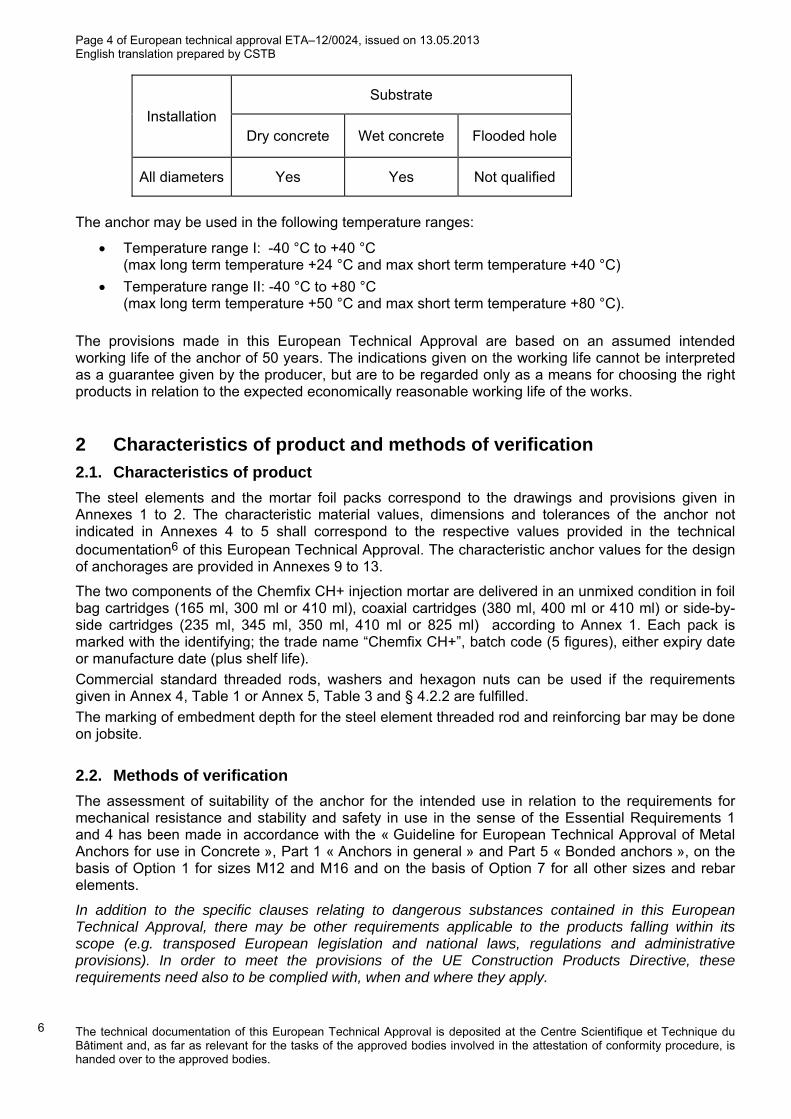
The anchor may be installed in dry or wet concrete for all diameters (use category 1).
Page 4 of European technical approval ETA–12/0024, issued on 13.05.2013 English translation prepared by CSTB
Installation
Substrate
Dry concrete Wet concrete Flooded hole
All diameters Yes Yes Not qualified
The anchor may be used in the following temperature ranges:
Temperature range I: -40 °C to +40 °C (max long term temperature +24 °C and max short term temperature +40 °C)
Temperature range II: -40 °C to +80 °C (max long term temperature +50 °C and max short term temperature +80 °C).
The provisions made in this European Technical Approval are based on an assumed intended working life of the anchor of 50 years. The indications given on the working life cannot be interpreted as a guarantee given by the producer, but are to be regarded only as a means for choosing the right products in relation to the expected economically reasonable working life of the works.
2 Characteristics of product and methods of verification
2.1. Characteristics of product
The steel elements and the mortar foil packs correspond to the drawings and provisions given in Annexes 1 to 2. The characteristic material values, dimensions and tolerances of the anchor not indicated in Annexes 4 to 5 shall correspond to the respective values provided in the technical documentation6 of this European Technical Approval. The characteristic anchor values for the design of anchorages are provided in Annexes 9 to 13.
The two components of the Chemfix CH+ injection mortar are delivered in an unmixed condition in foil bag cartridges (165 ml, 300 ml or 410 ml), coaxial cartridges (380 ml, 400 ml or 410 ml) or side-by-side cartridges (235 ml, 345 ml, 350 ml, 410 ml or 825 ml) according to Annex 1. Each pack is marked with the identifying; the trade name “Chemfix CH+”, batch code (5 figures), either expiry date or manufacture date (plus shelf life).
Commercial standard threaded rods, washers and hexagon nuts can be used if the requirements given in Annex 4, Table 1 or Annex 5, Table 3 and § 4.2.2 are fulfilled.
The marking of embedment depth for the steel element threaded rod and reinforcing bar may be done on jobsite.
2.2. Methods of verification
The assessment of suitability of the anchor for the intended use in relation to the requirements for mechanical resistance and stability and safety in use in the sense of the Essential Requirements 1 and 4 has been made in accordance with the « Guideline for European Technical Approval of Metal Anchors for use in Concrete », Part 1 « Anchors in general » and Part 5 « Bonded anchors », on the basis of Option 1 for sizes M12 and M16 and on the basis of Option 7 for all other sizes and rebar elements.
In addition to the specific clauses relating to dangerous substances contained in this European Technical Approval, there may be other requirements applicable to the products falling within its scope (e.g. transposed European legislation and national laws, regulations and administrative provisions). In order to meet the provisions of the UE Construction Products Directive, these requirements need also to be complied with, when and where they apply.
6 The technical documentation of this European Technical Approval is deposited at the Centre Scientifique et Technique du Bâtiment and, as far as relevant for the tasks of the approved bodies involved in the attestation of conformity procedure, is handed over to the approved bodies.

Page 5 of European technical approval ETA–12/0024, issued on 13.05.2013 English translation prepared by CSTB
3 Evaluation of Conformity and CE marking
3.1 Attestation of conformity system
The system of attestation of conformity 2 (i) (referred to as system 1) according to Council Directive 89/106/EEC Annex III laid down by the European Commission provides:
a) Tasks for the manufacturer:
1. Factory production control, 2. Further testing of samples taken at the factory by the manufacturer in accordance with a
prescribed test plan.
b) Tasks for the approved body:
3. Initial type-testing of the product, 4. Initial inspection of factory and of factory production control, 5. Continuous surveillance, assessment and approval of factory production control.
3.2. Responsibilities
3.2.1 Tasks of the manufacturer
3.2.1.1 Factory production control
The manufacturer shall have a factory production control system in the plant and shall exercise permanent internal control of production. All the elements, requirements and provisions adopted by the manufacturer are documented in a systematic manner in the form of written policies and procedures. This production control system ensures that the product is in conformity with the European Technical Approval.
The manufacturer shall only use raw materials supplied with the relevant inspection documents as laid down in the prescribed test plan7. The incoming raw materials shall be subject to controls and tests by the manufacturer before acceptance. Check of incoming materials such as resin and hardener shall include control of the inspection documents presented by suppliers (comparison with nominal values) by verifying appropriate properties.
The frequency of controls and tests conducted during production is laid down in the prescribed test plan taking account of the automated manufacturing process of the anchor.
The results of factory production control are recorded and evaluated.
The records shall be presented to the inspection body during the continuous surveillance. On request, they shall be presented to the Centre Scientifique et Technique du Bâtiment.
Details of the extent, nature and frequency of testing and controls to be performed within the factory production control shall correspond to the prescribed test plan which is part of the technical documentation of this European Technical Approval.
3.2.1.2 Other tasks of the manufacturer
The manufacturer shall, on the basis of a contract, involve a body which is approved for the tasks referred to in section 3.1 in the field of in order to undertake the actions laid down in section 3.2.2. For this purpose, the control plan referred to in sections 3.2.1 and 3.2.2 shall be handed over by the manufacturer to the approved body involved. The manufacturer shall make a declaration of conformity, stating that the construction product is in conformity with the provisions of this European technical approval.
3.2.2 Tasks of approved bodies
3.2.2.1 Initial type-testing of the product
For initial type-testing the results of the tests performed as part of the assessment for the European Technical Approval shall be used unless there are changes in the production line or plant. In such
7 The prescribed test plan has been deposited at the Centre Scientifique et Technique du Bâtiment and is only made available to the approved bodies involved in the conformity attestation procedure.

Page 6 of European technical approval ETA–12/0024, issued on 13.05.2013 English translation prepared by CSTB
cases the necessary initial type-testing has to be agreed between the Centre Scientifique et Technique du Bâtiment and the approved bodies involved.
3.2.2.2 Initial inspection of factory and of factory production control
The approved body shall ascertain that, in accordance with the prescribed test plan, the factory and the factory production control are suitable to ensure continuous and orderly manufacturing of the anchor according to the specifications mentioned in 2.1 as well as to the Annexes to the European Technical Approval.
The approved certification body involved by the manufacturer shall issue an EC certificate of conformity of the product stating the conformity with the provisions of this European technical approval
3.2.2.3 Continuous surveillance
The approved certification body involved by the manufacturer shall visit the factory at least once a year for regular inspection. It has to be verified that the system of factory production control and the specified automated manufacturing process are maintained taking account of the prescribed test plan.
Continuous surveillance and assessment of factory production control have to be performed according to the prescribed test plan.
The results of product certification and continuous surveillance shall be made available on demand by the certification body or inspection body, respectively, to the Centre Scientifique et Technique du Bâtiment. In cases where the provisions of the European Technical Approval and the prescribed test plan are no longer fulfilled the conformity certificate shall be withdrawn and CSTB informed without delay.
3.3. CE-Marking
The CE marking shall be affixed on each packaging of anchors. The symbol « CE » shall be accompanied by the following information:
Commercial name;
Name or identifying mark of the producer and manufacturing plant;
Name of approval body and ETA number;
Identification number of the certification body;
Number of the EC certificate of conformity;
Use category ETAG 001-5 Option 1 or 7 (see § 2.2);
The last two digits of the year in which the CE-marking was affixed;
Size.
4 Assumptions under which the suitability of the product for the intended use was favourably assessed
4.1. Manufacturing
The anchor is manufactured in accordance with the provisions of the European Technical Approval using the automated manufacturing process as identified during inspection of the plant by the Centre Scientifique et Technique du Bâtiment and the approved body and laid down in the technical documentation. Changes to the product or production process, which could result in this deposited data/information being incorrect, should be notified to the Centre Scientifique et Technique du Bâtiment before the changes are introduced. The Centre Scientifique et Technique du Bâtiment will decide whether or not such changes affect the ETA and consequently the validity of the CE marking on the basis of the ETA and if so whether further assessment or alterations to the ETA shall be necessary

Page 7 of European technical approval ETA–12/0024, issued on 13.05.2013 English translation prepared by CSTB
4.2. Installation
4.2.1. Design of anchorages
The suitability of the anchor for the intended use is given under the following conditions: The anchorages are designed in accordance with the EOTA Technical Report TR 0298 "Design of bonded anchors" under the responsibility of an engineer experienced in anchorages and concrete work. Verifiable calculation notes and drawings are prepared taking account of the loads to be anchored. The position of the anchor is indicated on the design drawings (e.g. position of the anchor relative to reinforcement or to supports, etc.).
Post-installed reinforcing bars may be used as anchor designed in accordance with the EOTA Technical Report TR 029 only. The basic assumptions for the design according to anchor theory shall be observed. This includes the consideration of tension and shear loads and the corresponding failure modes as well as the assumption that the base material (concrete structural element) remains essentially in the serviceability limit state (either non-cracked or cracked) when the connection is loaded to failure. Such applications are e.g. concrete overlay or shear dowel connections or the connections of a wall predominantly loaded by shear and compression forces with the foundation, where the rebars act as dowels to take up shear forces. Connections with reinforcing bars in concrete structures designed in accordance with EN1992-1-1: 2004 (e.g. connection of a wall loaded with tension forces in one layer of the reinforcement with the foundation) are not covered by this European Technical Approval.
4.2.2. Installation of anchors
The suitability for use of the anchor can only be assumed if the anchor is installed as follows:
anchor installation carried out by appropriately qualified personnel and under the supervision of the person responsible for technical matters on the site;
use of the anchor only as supplied by the manufacturer without exchanging the components of an anchor;
commercial standard threaded rods, washers and hexagon nuts may also be used if the following requirements are fulfilled: • material, dimensions and mechanical properties of the metal parts according to the
specifications given in Annex 5, Table 3, • confirmation of material and mechanical properties of the metal parts by inspection certificate
3.1 according to EN 10204:2004, the documents shall be stored, • marking of the threaded rod with the envisage embedment depth. This may be done by the
manufacturer of the rod or the person on jobsite. anchor installation in accordance with the manufacturer’s specifications and drawings using the
tools indicated in the technical documentation of this European Technical Approval; checks before placing the anchor to ensure that the strength class of the concrete in which the
anchor is to be placed is in the range; check of concrete being well compacted, e.g. without significant air voids; keeping the effective anchorage depth; keeping of the edge distance and spacing to the specified values without minus tolerances; positioning of the drill holes without damaging the reinforcement; in case of aborted drill hole, the drill hole shall be filled with mortar; cleaning the hole in accordance with Annex 6 or 7; before brushing clean the brush and checking
whether the brush diameter according to Annex 8 Table 6 is sufficient. The brush shall produce natural resistance as it enters the anchor hole. If this is not the case a new brush or a brush with a larger diameter must be used;
anchor installation ensuring the specified embedment depth, that is the appropriate depth marking of the anchor not exceeding the concrete surface;
mortar injection by using the equipment including the special mixing nozzle shown in Annex 1; discarding the first portion of mortar of each new cartridge until an homogeneous colour is achieved; taking from the manufacturer instruction the admissible processing time (open time) of a
8 The Technical Report TR 029 "Design of Bonded Anchors" is published in English on EOTA website www.eota.eu.

Page 8 of European technical approval ETA–12/0024, issued on 13.05.2013 English translation prepared by CSTB
cartridge as a function of the ambient temperature of the concrete; filling the drill hole uniformly from the drill hole bottom, in order to avoid entrapment of air; removing the special mixing nozzle slowly bit by bit during pressing-out; filling the drill hole with a quantity of the injection mortar corresponding to 2/3 of the drill hole; inserting immediately the threaded rod, slowly and with a slight twisting motion, removing excess of injection mortar around the rod; observing the curing time according to Annex 8 Table 7 until the rod may be loaded; during curing of the injection mortar the temperature of the concrete must not fall below - 10°C and the temperature of the bond material must be +20°C;
application of the torque moment given in Annex 4 Table 1 using a calibrated torque wrench.
4.2.3. Responsibility of the manufacturer
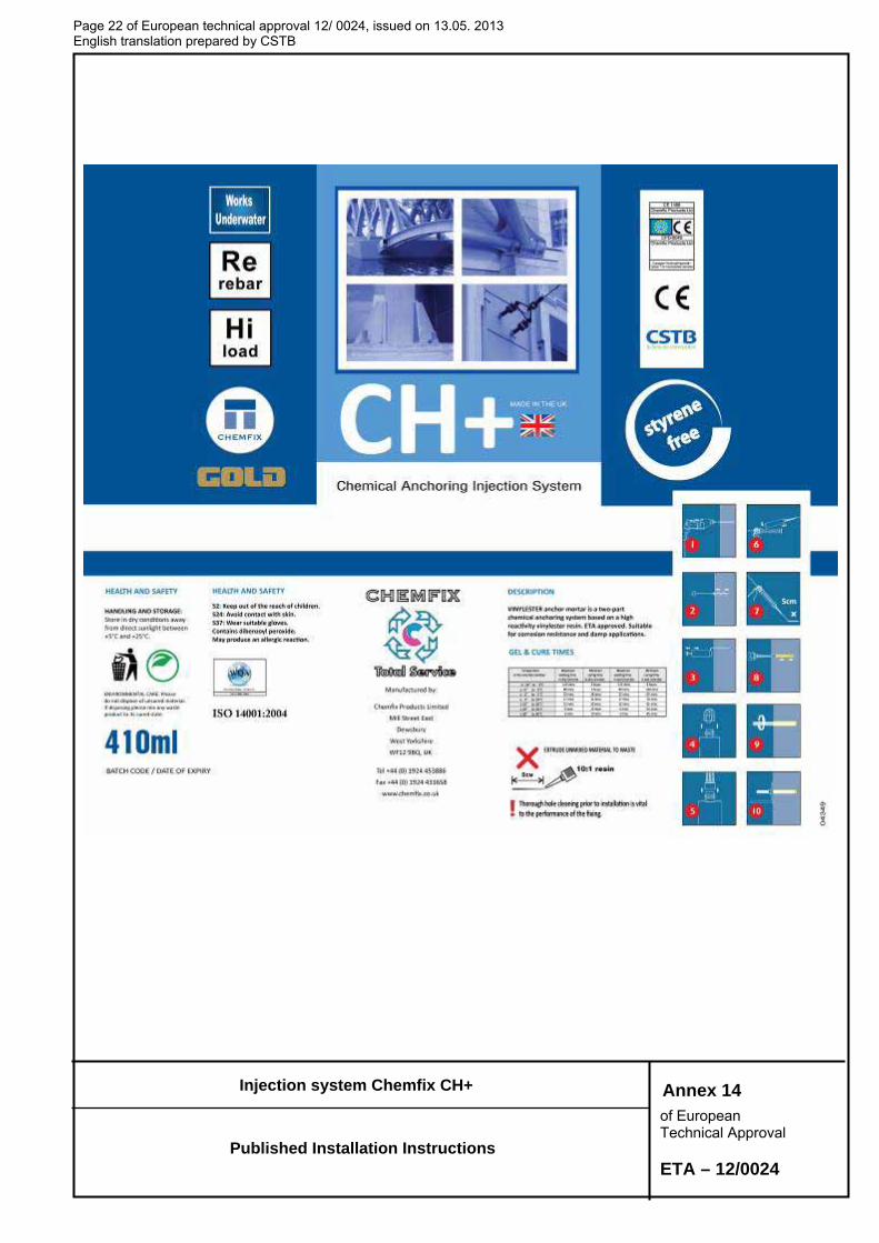
It is the manufacturer’s responsibility to ensure that the information on the specific conditions according to 1 and 2 including Annexes referred to as well as in sections in 4.2.1 and 4.2.2 is given to those who are concerned. This information may be made by reproduction of the respective parts of the European Technical Approval. In addition all installation data shall be shown clearly on the package and/or on an enclosed instruction sheet, preferably using illustration(s).
The minimum data required are:
drill bit diameter, hole depth, diameter of anchor rod, minimum effective anchorage depth, information on the installation procedure, including cleaning of the hole with the cleaning
equipments, preferably by means of an illustration, material and property class of metal parts acc. to Annex 5, Table 3 & 4, anchor component installation temperature, ambient temperature of the concrete during installation of the anchor, admissible processing time (open time or gel time) of the mortar, curing time until the anchor may be loaded as a function of the ambient temperature in the
concrete during installation, maximum torque moment, identification of the manufacturing batch,
All data shall be presented in a clear and explicit form.
5 Recommendations concerning packaging, transport and storage.
The mortar cartridges shall be protected against sun radiation and shall be stored according to the manufacturer’s installation instructions in dry conditions at temperatures of at least +5°C to not more than +25°C.
Mortar cartridges (foil bag or rigid cartridges) with expired shelf life must no longer be used.
The anchor shall only be packaged and supplied as a complete unit. Foil bags (or cartridges) may be packed separately from metal parts.
The original French version is signed by
Le Directeur Technique C. BALOCHE

Page 9 of European technical approval ETA–12/0024, issued on 13.05.2013 English translation prepared by CSTB.
Injection system Chemfix CH+
of European Technical Approval ETA – 12/0024
Injection Mortar : Chemfix CH+ Resin System
Chubpac® and ChubSeal®
Foil Bag Cartridge 165ml - 410ml
Coaxial Cartridge 380ml - 410ml
Side by Side Cartridge 235ml - 825ml
Marking:
CH+ Batch code, either expiry date or manufacturing date with shelf life
T-Flow™ Mixer with hanger
Annex 1
Product and intended use

Page 10 of European technical approval ETA–12/0024, issued on 13.05.2013 English translation prepared by CSTB.
Injection system Chemfix CH+
of European Technical Approval ETA – 12/0024
Anchor rod and rebar:
Threaded Steel Stud, Nut and Washer Sizes M8, M10, M12, M16, M20, M24.
Commercial standard rod with: - Materials, dimensions and mechanical properties (Table 1a) - Inspection certificate 3.1 acc. to EN 10204:2004 - Marking of embedment depth
Rebar Diameter Ø 8mm, Ø 10mm, Ø 12mm, Ø 14mm, Ø 16mm, Ø 20mm, Ø 25mm
Product and intended use
Annex 2

Page 11 of European technical approval ETA–12/0024, issued on 13.05.2013 English translation prepared by CSTB.
Injection system Chemfix CH+
of European Technical Approval ETA – 12/0024
Intended use Use category 1 (according to ETAG 001-5):
Installation in dry or wet concrete.
(Not permitted in flooded holes)
Overhead installation is not permitted
Installation in cracked concrete for threaded rods sizes M12 and M16 only
Temperature ranges -40°C to +40°C (max. short term temperature +40°C and max. long term temperature +24°C) -40°C to +80°C (max. short term temperature +80°C and max. long term temperature +50°C)
Annex 3
Installed anchor and intended use

Page 12 of European technical approval ETA–12/0024, issued on 13.05.2013 English translation prepared by CSTB.
Injection system Chemfix CH+
of European Technical Approval ETA – 12/0024
Table 1: Installation details for anchor rods
Anchor size M8 M10 M12 M16 M20 M24
Diameter of anchor rod d [mm] 8 10 12 16 20 24
Range of anchorage depth hef min [mm] 60 60 70 80 90 100
and bore hole depth ho max [mm] 160 200 240 320 400 480
Nominal anchorage depth hef [mm] 80 90 110 125 170 210
Nominal diameter of drill bit do [mm] 10 12 14 18 24 28
Diameter of clearance hole in the fixture df [mm] 9 12 14 18 22 26
Maximum torque moment Tmax [Nm] 10 20 30 60 90 140
Minimum thickness of concrete member hmin [mm] hef + 30mm ≥ 100mm
hef + 2do
Minimum spacing Smin [mm] 40 50 60 80 100 120
Minimum edge distance Cmin [mm] 40 50 60 80 100 120
Table 2 - Installation details for rebars
Rebar Diameter Ø8 Ø10 Ø12 Ø14 Ø16 Ø20 Ø25
Diameter of element D [mm] 8 10 12 14 16 20 25
Range of anchorage depth hef min [mm] 60 60 70 75 80 90 100
and bore hole depth ho max [mm] 160 200 240 280 320 400 500
Nominal diameter of drill bit do [mm] 12 14 16 18 20 25 32
Minimum thickness of concrete member
hmin [mm]hef + 30mm ≥ 100mm
hef + 2do
Minimum spacing Smin [mm] 40 50 60 70 80 100 125
Minimum edge distance Cmin [mm] 40 50 60 70 80 100 125
Annex 4
Installation details Threaded rods and rebars
Page 13 of European technical approval 12/ 0024, issued on 13.05.2013 English translation prepared by CSTB
Injection system Chemfix CH+
of European Technical Approval ETA – 12/0024
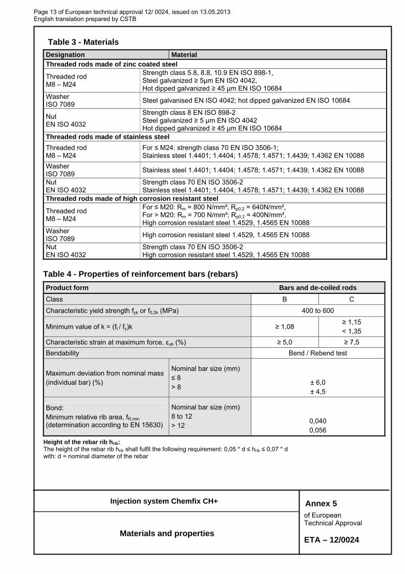
Table 3 - Materials
Designation Material Threaded rods made of zinc coated steel
Threaded rod M8 – M24
Strength class 5.8, 8.8, 10.9 EN ISO 898-1, Steel galvanized ≥ 5µm EN ISO 4042, Hot dipped galvanized ≥ 45 µm EN ISO 10684
Washer ISO 7089
Steel galvanised EN ISO 4042; hot dipped galvanized EN ISO 10684
Nut EN ISO 4032
Strength class 8 EN ISO 898-2 Steel galvanized ≥ 5 µm EN ISO 4042 Hot dipped galvanized ≥ 45 µm EN ISO 10684
Threaded rods made of stainless steel
Threaded rod M8 – M24
For ≤ M24: strength class 70 EN ISO 3506-1; Stainless steel 1.4401; 1.4404; 1.4578; 1.4571; 1.4439; 1.4362 EN 10088
Washer ISO 7089
Stainless steel 1.4401; 1.4404; 1.4578; 1.4571; 1.4439; 1.4362 EN 10088
Nut EN ISO 4032
Strength class 70 EN ISO 3506-2 Stainless steel 1.4401; 1.4404; 1.4578; 1.4571; 1.4439; 1.4362 EN 10088
Threaded rods made of high corrosion resistant steel
Threaded rod M8 – M24
For ≤ M20: Rm = 800 N/mm²; Rp0,2 = 640N/mm², For > M20: Rm = 700 N/mm²; Rp0,2 = 400N/mm², High corrosion resistant steel 1.4529, 1.4565 EN 10088
Washer ISO 7089
High corrosion resistant steel 1.4529, 1.4565 EN 10088
Nut EN ISO 4032
Strength class 70 EN ISO 3506-2 High corrosion resistant steel 1.4529, 1.4565 EN 10088
Table 4 - Properties of reinforcement bars (rebars)
Product form Bars and de-coiled rods
Class B C
Characteristic yield strength fyk or f0,2k (MPa) 400 to 600
Minimum value of k = (ft / fy)k ≥ 1,08 ≥ 1,15 < 1,35
Characteristic strain at maximum force, εuk (%) ≥ 5,0 ≥ 7,5
Bendability Bend / Rebend test
Maximum deviation from nominal mass (individual bar) (%)
Nominal bar size (mm) ≤ 8 > 8
± 6,0 ± 4,5
Bond: Minimum relative rib area, fR,min (determination according to EN 15630)
Nominal bar size (mm) 8 to 12 > 12
0,040 0,056
Height of the rebar rib hrib: The height of the rebar rib hrib shall fulfil the following requirement: 0,05 * d ≤ hrib ≤ 0,07 * d with: d = nominal diameter of the rebar
Annex 5
Materials and properties

Page 14 of European technical approval 12/ 0024, issued on 13.05.2013 English translation prepared by CSTB
Injection system Chemfix CH+
of European Technical Approval ETA – 12/0024
Table 5a - Installation parameters: drilling, hole cleaning and installation
Instructions for use
Bore hole drilling
Drill hole in the substrate to the required embedment depth using the appropriately sized carbide drill bit.
Bore hole cleaning Just before setting an anchor, the bore hole must be free of dust and debris.
a) Manual air cleaning (MAC) for all bore hole diameters do ≤ 24mm and bore hole depth ho ≤ 10d
X 4
The Chemfix manual pump shall be used for blowing out bore holes up to diameters do ≤ 24mm and embedment depths up to hef ≤ 10d. Blow out at least 4 times from the back of the bore hole, using an extension if needed.
X 4 Brush 4 times with the specified brush size (see Table 6) by inserting the Chemfix steel brush to the back of the hole (if needed with an extension) in a twisting motion and removing it.
X 4 Blow out again with manual pump at least 4 times.
b) Compressed air cleaning (CAC) for all bore hole diameters do and all bore hole depths
X 2 Blow 2 times from the back of the hole (if needed with a nozzle extension) over the whole length with oil-free compressed air (min. 6 bar at 6 m³/h).
X 2 Brush 2 times with the specified brush size (see Table 6) by inserting the Chemfix steel brush to the back of the hole (if needed with an extension) in a twisting motion and removing it.
X 2 Blow out again with compressed air at least 2 times.
Annex 6
Instructions for use I

Page 15 of European technical approval 12/ 0024, issued on 13.05.2013 English translation prepared by CSTB
Injection system Chemfix CH+
of European Technical Approval ETA – 12/0024
Table 5b - Installation parameters: drilling, hole cleaning and installation
Instructions for use
Remove the threaded cap from the cartridge.
Tightly attach the T-Flow™ mixing nozzle. Do not modify the mixer in any way. Made sure the mixing element is inside the mixer. Use only the supplied mixer.
Insert the cartridge into the Chemfix dispenser gun.
Discard the initial trigger pulls of adhesive. Depending on the size of the cartridge, an initial amount of adhesive mix must be discarded. Discard quantities are - 5cm for between 150ml, 300ml & 400ml Foil Pack - 10cm for all other cartridges
Inject the adhesive starting at the back of the hole, slowly withdrawing the mixer with each trigger pull. Fill holes approximately 2/3 full, to ensure that the annular gap between the anchor and the concrete is completely filled with adhesive along the embedment depth.
Before use, verify that the threaded rod is dry and free of contaminants. Install the threaded rod to the required embedment depth during the open gel time tgel has elapsed. The working time tgel is given in Table 7.
The anchor can be loaded after the required curing time tcure (see Table 7). The applied torque shall not exceed the values Tmax given in Table 1.
Annex 7
Instructions for use II

Page 16 of European technical approval 12/ 0024, issued on 13.05.2013 English translation prepared by CSTB
Injection system Chemfix CH+
of European Technical Approval ETA – 12/0024
Table 6: Bore hole cleaning method with Steel brush
Threaded rod And rebar
Size
Nominal drill bit
diameter do (mm)
Steel Brush Cleaning methods
Manual cleaning (MAC)
Compressed air cleaning (CAC)
Studs
M8 10 12mm Yes … hef ≤ 80 mm
Yes
M10 12 14mm Yes … hef ≤ 100mm M12 14 16mm Yes … hef ≤ 120mm M16 18 20mm Yes … hef ≤ 160mm M20 24 26mm Yes … hef ≤ 200mm M24 28 30mm Yes … hef ≤ 240mm
Rebar
Ø8 12 14mm Yes … hef ≤ 80 mm
Yes
Ø10 14 16mm Yes … hef ≤ 100mm Ø12 16 18mm Yes … hef ≤ 120mm Ø14 18 20mm Yes … hef ≤ 140mm Ø16 20 22mm Yes … hef ≤ 160mm Ø20 25 28mm Yes … hef ≤ 200mm Ø25 32 34mm Yes … hef ≤ 240mm
Manual Cleaning (MAC): Chemfix hand pump recommended for Blowing out bore holes with diameters do≤ 24 mm and bore holes depth ho≤10d
Compressed air cleaning (CAC): Recommended air nozzle with an Orifice opening of minimum 3,5mm in diameter.
Table 7: Minimum curing time
Minimum base material temperature C°
Gel time (working time) Cure time
In dry/wet concrete
-10°C Tbase material < -5°C 125 min 8 hours -5°C Tbase material < 0°C 80 min 160 min 0° Tbase material < 5°C 25 min 90 min 5°C Tbase material < 10°C 17 min 70 min 10°C Tbase material < 20°C 12 min 65 min 20°C Tbase material < 30°C 6 min 60 min 30°C Tbase material 40°C 3 min 45 min
The temperature of the bond material must be ≥ 20°C
Annex 8
Installation and cleaning tools
Minimum installation times

Page 17 of European technical approval 12/ 0024, issued on 13.05.2013 English translation prepared by CSTB
Injection system Chemfix CH+
of European Technical Approval ETA – 12/0024
Table 8: Design method A, characteristic tension load values
Chemfix CH+ with threaded rods M8 M10 M12 M16 M20 M24
Steel failure Characteristic resistance, class 5.8 NRk,s [kN] 18 29 42 79 123 177 Characteristic resistance, class 8.8 NRk,s [kN] 29 46 67 126 196 282 Partial safety factor Ms,N
1) [-] 1,5 Characteristic resistance, class 10.9 NRk,s [kN] 36 58 84 157 245 353 Partial safety factor Ms,N
1) [-] 1.4 Characteristic resistance, A4-70 NRk,s [kN] 26 41 59 110 172 247 Partial safety factor Ms,N
1) [-] 1,87 Characteristic resistance, HCR NRk,s [kN] 29 46 67 126 196 247 Partial safety factor Ms,N
1) [-] 1,5 2,1
Combined Pull-out and Concrete cone failure 2) Diameter of threaded rod d [mm] 8 10 12 16 20 24 Characteristic bond resistance in non-cracked concrete C20/25
Temperature range I 3) : 40°C/24°C Rk [N/mm²] 10.0 9.5 9.0 8.0 7.5 7.0
Temperature range II3) : 80°C/50°C Rk [N/mm²] 9.0 8.0 7.5 7.0 6.5 6.0
Increasing factor for Rk,p in non-cracked concrete
c
C30/37 1,12 C40/50 1,23 C50/60 1,30
Characteristic bond resistance in cracked concrete C20/25
Temperature range I 3) : 40°C/24°C Rk [N/mm²] -6) -6) 3.5 3.5 -6) -6)
Temperature range II3) : 80°C/50°C Rk [N/mm²] -6) -6) 3.0 3.0 -6) -6)
Increasing factor for Rk,p in cracked concrete
c
C30/37 1,04 C40/50 1,07 C50/60 1,09
Splitting failure2)
Edge distance ccr,sp [mm] for
h / hef 4) ≥ 2,0 1,0 hef
1 .0 0
1 .2 0
1 .4 0
1 .6 0
1 .8 0
2 .0 0
2 .2 0
2 .4 0
0 .5 0 0 .7 5 1 .0 0 1 .2 5 1 .5 0 1 .7 5 2 .0 0 2 .2 5 2 .5 0
h/hef
c / h e f
2,0 > h / hef 4) > 1,3 4,6 hef - 1,8 h
h / hef 4) ≤ 1,3 2,25 hef
Spacing scr,sp [mm] 2 ccr,sp
Partial safety factor Mp =Mc =Msp 5) [-] 1,5 5) 1,5 5) 1,5 5) 1,5 5) 1,5 5) 1,5 5)
1) In absence of national regulations
2) Calculation of concrete and splitting, see chapter 4.2.1
3) Explanations, see chapter 1.2
4) h . concrete member thickness, hef ... effective anchorage depth 5) The partial safety factor 2 = 1,0 is included 6) Not qualified in cracked concrete
Annex 9
Threaded Rods :
Characteristic tension load values

Page 18 of European technical approval 12/ 0024, issued on 13.05.2013 English translation prepared by CSTB
Injection system Chemfix CH+
of European Technical Approval ETA – 12/0024
Table 9: Displacements under tension 6)
Chemfix CH+ with threaded rods M8 M10 M12 M16 M20 M24
Non cracked concrete temperature range I 7) : 40°C / 24°C
Displacement N0 [mm/(N/mm²)] 0,03 0,03 0,04 0,05 0,06 0,07
Displacement N [mm/(N/mm²)] 0,07 0,09 0,10 0,13 0,17 0,20
Non cracked concrete temperature range II 7): 80°C / 50°C
Displacement N0 [mm/(N/mm²)] 0,04 0,04 0,05 0,07 0,08 0,10
Displacement N [mm/(N/mm²)] 0,10 0,13 0,15 0,19 0,23 0,28
Cracked concrete temperature range I 7) : 40°C / 24°C
Displacement N0 [mm/(N/mm²)] - - 0,12 0,09 - -
Displacement N [mm/(N/mm²)] - - 0,64 0,55 - -
Cracked concrete temperature range II 7): 80°C / 50°C
Displacement N0 [mm/(N/mm²)] - - 0,17 0,13 - -
Displacement N [mm/(N/mm²)] - - 0,90 0,78 - - 6) Calculation of displacement under service load: Sd design value of bond stress
Displacement under short term loading = N0 · Sd/1,4 Displacement under long term loading = N · Sd/1,4
7) Explanation see chapter 1.2
Annex 10
Threaded Rods :
displacement under tension loads

Page 19 of European technical approval 12/ 0024, issued on 13.05.2013 English translation prepared by CSTB
Injection system Chemfix CH+
of European Technical Approval ETA – 12/0024
Table 10: Design method A, Characteristic shear load values
Chemfix CH+ with threaded rods M 8 M 10 M 12 M 16 M 20 M 24
Steel failure without lever arm
Characteristic resistance, class 5.8 VRk,s [kN] 9 15 21 39 61 88
Characteristic resistance, class 8.8 VRk,s [kN] 15 23 34 63 98 141
Characteristic resistance, class 10.9 VRk,s [kN] 18 29 42 79 123 156
Characteristic resistance, A4-70 VRk,s [kN] 13 20 30 55.0 86 124
Characteristic resistance, HCR VRk,s [kN] 15 23 34 62.8 98 124
Steel failure with lever arm
Characteristic resistance, class 5.8 M0Rk,s [Nm] 19 37 66 167 326 561
Characteristic resistance, class 8.8 M0Rk,s [Nm] 30.0 60 105 266 519 898
Characteristic resistance, class 10.9 M0Rk,s [Nm] 38 75 131 333 649 893
Characteristic resistance, A4-70 M0Rk,s [Nm] 26 53 92 233 454 625
Characteristic resistance, HCR M0Rk,s [Nm] 30 60 105 266 519 786
Partial safety factor steel failure
grade 5.8 or 8.8 Ms,V 1) [-] 1,25
grade 10.9 Ms,V 1) [-] 1,50
A4-70 Ms,V 1) [-] 1,56
HCR Ms,V 1) [-] 1,25 1,75
Concrete pryout failure
Factor in equation (5.7) of Technical Report TR 029 for the design of bonded anchors
k [-] 2,0
Partial safety factor Mcp 1) [-] 1,5 2)
Concrete edge failure3)
Partial safety factor Mc 1) [-] 1,5 2)
1) In absence of national regulations. 2) The partial safety factor 2 = 1,0 is included. 3) Concrete edge failure see chapter 5.2.3.4 of Technical Report TR 029.
Table 11: Displacement under shear load 5)
Chemfix CH+ with threaded rods M8 M10 M12 M16 M20 M24
Displacement V0 [mm/kN] 0,06 0,06 0,05 0,04 0,04 0,03
Displacement V [mm/kN] 0,09 0,08 0,08 0,06 0,06 0,05 5) Calculation of displacement under service load: VSd design value of shear load
Displacement under short term loading = V0 · VSd/1,4 Displacement under long term loading = V · VSd/1,4
Annex 11
Threaded Rods :
Characteristic shear load values and displacements under shear load

Page 20 of European technical approval 12/ 0024, issued on 13.05.2013 English translation prepared by CSTB
Injection system Chemfix CH+
of European Technical Approval ETA – 12/0024
Table 12: Design method A, Characteristic tension load values
Chemfix CH+ with rebar Ø8 Ø10 Ø12 Ø14 Ø16 Ø20 Ø25
Steel failure rebar
Characteristic resistance for rebar BSt 500 S acc. to DIN 488
1) NRk,s [kN] 28 43 62 85 111 173 270
Partial safety factor for rebar BSt 500 S acc. to DIN 488
2) Ms,N 3) [-] 1,4
Combined Pull-out and Concrete cone failure4)
Diameter of rebar d [mm] 8 10 12 14 16 20 25
Characteristic bond resistance in non-cracked concrete C20/25
Temperature range I 5): 40°C/24°C Rk [N/mm²] 7,0 7,5 7,0 7,0 6,5 6,5 6,0
Temperature range II 5): 80°C/50°C Rk [N/mm²] 6.5 6.5 6,0 6,0 6,0 5,5 5,5
Increasing factor for Rk,p in non cracked concrete
C30/37 1,12
c C40/50 1,23
C50/60 1,30
Splitting failure 4)
Edge distance ccr,sp [mm] for
h / hef 6) ≥ 2,0 1,0 hef
2,0 > h / hef 6) > 1,3 4,6 hef - 1,8 h
h / hef 6) ≤ 1,3 2,26 hef
Spacing scr,sp [mm] 2 ccr,sp
Partial safety factor Mp =Mc =Msp 3) [-] 1,8 7) 1,8 7) 1,8 7) 1,8 7) 1,8 7) 1,8 7) 1,8 7)
1) The characteristic tension resistance NRk,s for rebars that do not fulfil the requirements acc. DIN 488 shall be calculated acc. Technical
Report TR029, Equation (5.1). 2) The partial safety factor Ms,N for rebars that do not fulfil the requirements acc. DIN 488 shall be calculated acc. Technical Report TR029,
Equation (3.3a). 3) In absence of national regulations
4) Calculation of concrete failure and splitting see chapter 4.2.1 5) Explanation see chapter 1.2 6) h … concrete member thickness, hef effective anchorage depth 7) The partial safety factor 2 = 1,2 is included.
Table 13: Displacements under tension load 8)
Chemfix CH+ with rebar Ø8 Ø10 Ø12 Ø14 Ø16 Ø20 Ø25
Temperature range I 9): 40°C / 24°C
Displacement N0 [mm/(N/mm²)] 0,03 0,03 0,04 0,04 0,05 0,06 0,07
Displacement N [mm/(N/mm²)] 0,07 0,09 0,10 0,12 0,13 0,17 0,20
Temperature range II 9): 80°C / 50°C
Displacement N0 [mm/(N/mm²)] 0,04 0,04 0,05 0,06 0,07 0,08 0,10
Displacement N [mm/(N/mm²)] 0,10 0,13 0,15 0,17 0,19 0,23 0,29 8) Calculation of displacement under service load: Sd design value of bond stress
Displacement under short term loading = N0 · Sd/1,4 Displacement under long term loading = N · Sd/1,4
9) Explanation see chapter 1.2
Regarding design of post-installed rebar as anchor see chapter 4.2.1
Annex 12
Rebars:
Characteristic tension load values and displacement under tension loads

Page 21 of European technical approval 12/ 0024, issued on 13.05.2013 English translation prepared by CSTB
Injection system Chemfix CH+
of European Technical Approval ETA – 12/0024
Table 14: Design method A, Characteristic shear load values
Chemfix CH+ with rebar Ø8 Ø10 Ø12 Ø14 Ø16 Ø20 Ø25
Steel failure without lever arm
Characteristic shear resistance for rebar BSt 500 S acc. to DIN 488 1)
VRk,s [kN] 14 22 31 42 55 86 135
Partial safety factor for rebar BSt 500 S acc. to DIN 488
2) Ms,V 3) [-] 1,5
Steel failure with lever arm
Characteristic shear resistance for rebar BSt 500 S acc. to DIN 488 4)
M0Rk,s [Nm] 33 65 112 178 265 518 1012
Partial safety factor for rebar BSt 500 S acc. to DIN 488 2) Ms,V
3) [-] 1,5
Concrete pryout failure
Factor in equation (5.7) of Technical Report TR 029 for the design of bonded anchors
k [-] 2,0
Partial safety factor Mcp 3) [-] 1,5 5)
Concrete edge failure 6)
Partial safety factor Mc 3) [-] 1,5 5)
1) The characteristic shear resistance VRk,s for rebars that do not fulfil the requirements acc. DIN 488 shall be calculated acc.
Technical Report TR029, Equation (5.6). 2) The partial safety factor Ms,V for rebars that do not fulfil the requirements acc. DIN 488 shall be calculated acc. Technical
Report TR029, Equation (3.3b).or (3.3c).. 3) In absence of national regulations 4) The characteristic bending resistance M0
Rk,s for rebars that do not fulfil the requirements acc. DIN 488 shall be calculated acc. Technical Report TR029, Equation (5.6b).
5) The partial safety factor 2 = 1,0 is included. 6) Concrete edge failure see chapter 5.2.3.4 of Technical Report TR 029.
Table 15: Displacements under shear load 7)
Chemfix CH+ with rebar Ø8 Ø10 Ø12 Ø14 Ø16 Ø20 Ø25
Displacement V0 [mm/kN] 0,06 0,05 0,05 0,04 0,04 0,04 0,03
Displacement V [mm/kN] 0,09 0,08 0,07 0,06 0,06 0,05 0,05 7) Calculation of displacement under service load: VSd design value of shear load
Displacement under short term loading = N0 · VSd/1,4 Displacement under long term loading = V · VSd/1,4
Regarding design of post-installed rebar as anchor see chapter 4.2.1
Annex 13
Rebars: Characteristic values and displacement for shear load
Page 22 of European technical approval 12/ 0024, issued on 13.05. 2013 English translation prepared by CSTB
Injection system Chemfix CH+
of European Technical Approval ETA – 12/0024
Annex 14
Published Installation Instructions