Embed Size (px)
Citation preview
CSL-DOC-10-53451 Released 1.Introduction
Copyright © 2010 by Cosylab Page 1 of 52 Public
European Spallation Source
Control System Study
Revision: 1.0
Status: Released
Repository: acc
Project: ACC-ESS-CS_Study
Folder: ESS-SVN/CS/doc
Document ID: CSL-DOC-10-53451
File: DOC-ESS_Control_System_Study.doc
Owner: Igor Verstovšek
Last modification: March 31, 2010
Created: February 10, 2010
Scope
This document identifies the fundamental requirements of the ESS control system given the
existing understanding of the ESS design. A rough conceptual design will be prepared, emphasizing
the most critical issues and technologies; comparing existing solutions and discussing whether they
are sufficient or whether some critical new development must be envisioned. The document
addresses the issues set forth in the document memo_cosylab_091211.pdf, written by Steve Peggs
and Todd Satogata on December 10, 2009.
1.Introduction Released CSL-DOC-10-53451
Public Page 2 of 52 Copyright © 2010 by Cosylab
Executive Summary
Control system development is a low risk activity in constructing the European Spallation Source
(ESS). The risks can be classified as technical and organizational. The reasons for a small technical
risk are: 1) major control system software platforms have matured significantly in the last decade,
with focus of development shifting towards ease of adoption and usability, 2) large improvements
of CPU performance have simplified software and hardware development, with increasing
availability of standard commercial off the shelf (COTS) hardware components.
ESS will be constructed by a number of partner institutions in an international collaboration, thus
increasing organizational risk as control system integration will be performed by a large number of
independent teams. In addition, control system integration comes late in the project and integrates
with all other subsystems. As a consequence, problems in this phase can soon affect the critical
path of the overall project.
In order to address these risks and to facilitate control system development, several assumptions
have already been made:
1) ESS will use the EPICS control system.
2) Linux will be the operating system in the ESS controls service tier.
3) ESS will use the Oracle relational database system.
Control system recommendations are grouped according to time of their applicability, as some
decisions have to be made immediately and some should be deferred to later stages in the project.
In this document, the recommendations are classified as: 1) immediate recommendations (April
2010), 2) recommendations for the end of the design update phase (end of 2012), 3)
recommendations for construction phase (end of 2016).
The most important immediate recommendations are:
1) Initiate collaborations on control system development with similar projects, in particular
SNS, ITER, FRIB, XFEL and JLab 12 GeV Upgrade.
2) Join the XAL application development framework collaboration.
3) Introduce a naming convention early in the project. Decide if the same naming convention
names equipment as well as control signals.
4) Provide a standardized ―Control Box‖ platform to ESS partner institutions, with first
prototype delivery in late 2010.
5) Release Control Box software and hardware in (approximately) yearly cycles.
6) Integrate the control system of the linac and the target.
CSL-DOC-10-53451 Released 1.Introduction
Copyright © 2010 by Cosylab Page 3 of 52 Public
Table of Contents
1. Introduction 5 1.1. Working Assumptions and Recommendations........................................................ 5
1.1.1. Assumptions .................................................................................................. 5 1.1.2. Immediate Recommendations and Best Practices ......................................... 6 1.1.3. Three Year Milestone Recommendations ...................................................... 6 1.1.4. Seven Year Milestone Recommendations ...................................................... 8
1.2. Glossary of Terms .................................................................................................. 9 1.3. References ........................................................................................................... 10
2. Organizational Issues 13 2.1. Project Planning ................................................................................................... 13
2.1.1. Top Down Planning ...................................................................................... 14 2.1.2. Bottom Up Planning ..................................................................................... 15
2.2. Project Management System ................................................................................ 16 2.3. Development Procedures ..................................................................................... 16
2.3.1. Development Guidelines .............................................................................. 17 2.3.2. Signal List .................................................................................................... 18 2.3.3. Self-description ............................................................................................ 18 2.3.4. Development Infrastructure .......................................................................... 18 2.3.5. Quality Management .................................................................................... 19
3. Architecture 22 3.1. Scope of Control System ...................................................................................... 23 3.2. The “Control Box” Metaphor ................................................................................. 23
3.2.1. Control Box of Complex Subsystems ........................................................... 25 3.2.2. Control Box Development ............................................................................ 26
3.3. Equipment Interface ............................................................................................. 26 3.3.1. I/O Interfaces ............................................................................................... 27 3.3.2. Hardware Platforms ..................................................................................... 27 3.3.3. Software Platforms ....................................................................................... 31
3.4. Service Tier .......................................................................................................... 32 3.4.1. Database ..................................................................................................... 32 3.4.2. Alarm System............................................................................................... 33
3.5. Control Room Software ........................................................................................ 34 3.6. Computer Networks .............................................................................................. 34 3.7. Software Frameworks ........................................................................................... 36
3.7.1. XAL .............................................................................................................. 36 3.7.2. Control System Studio ................................................................................. 37 3.7.3. Other Frameworks ....................................................................................... 37 3.7.4. Comparison of Software Frameworks .......................................................... 37 3.7.5. Tools ............................................................................................................ 39
4. Data Management 41 4.1. Bottom Up vs. Top Down Approach ...................................................................... 41 4.2. Naming Convention .............................................................................................. 43 4.3. Machine Model ..................................................................................................... 44

1.Introduction Released CSL-DOC-10-53451
Public Page 4 of 52 Copyright © 2010 by Cosylab
5. Hard Real-Time Subsystems 45 5.1. Machine Timing .................................................................................................... 46
5.1.1. Overview ...................................................................................................... 46 5.1.2. Timing System Generic Architecture ............................................................ 46
5.2. Low Level Radio Frequency (LLRF) ..................................................................... 49
6. Operations and Maintenance Use Cases 50 6.1. User Access and Security ..................................................................................... 50 6.2. Control Room Layout ............................................................................................ 50 6.3. Control Room Applications ................................................................................... 50 6.4. Analogue Signals.................................................................................................. 51 6.5. Electronic Log Book .............................................................................................. 51
Figures
Figure 1: planned staffing level for the Integrated Control System (ICS) throughout the construction part of the SNS project. ................................................................ 15
Figure 2: a possible development process workflow. .................................................................. 20 Figure 3: a three-tier architecture of the ESS control system. .................................................... 22 Figure 4: a schematic of example Control Box components for a representative
Control Box example. .............................................................................................. 24 Figure 5: the EPICS BEAST alarm system architecture [37]. ..................................................... 34 Figure 6: flow of model data for top-down ESS control system design. ...................................... 42 Figure 7: timing-system architecture. .......................................................................................... 47
Tables
Table 1: comparison of VME, ATCA and PCI hardware platforms. ............................................ 30 Table 2: comparison of XAL, CSS, EDM and Qt software frameworks. ..................................... 39
CSL-DOC-10-53451 Released 1.Introduction
Copyright © 2010 by Cosylab Page 5 of 52 Public
1. INTRODUCTION
1.1. WORKING ASSUMPTIONS AND RECOMMENDATIONS
The ESS project will have the following major milestones:
The three year milestone: end of year 2012, end of the Design Update Phase.
The seven year milestone: end of year 2016, just before installation gets into full swing.
Some decisions should be made well before the first milestone and others should be deferred until
the seven year milestone. Therefore, the recommendations in this document are classified according
to the relevant milestones:
Assumptions: decisions that were already taken and are treated as input parameters in this
document. Marked as Assumption.
Immediate recommendations for the project (April 2010) and best practices that should
be taken into account early on: marked as Recommendation (I).
Three year milestone recommendations: marked as Recommendation (III).
Seven year milestone recommendations: marked as Recommendation (VII).
Assumptions and recommendations from the whole document are gathered below, as a conclusion
and quick reference for technical audience.
1.1.1. Assumptions
1.1.1.1. Organizational Assumptions
Assumption #23: The personnel protection system (PPS) and machine protection systems (MPS)
will not be direct parts of the single controls network.
Assumption #24: All subsystems that need to take into account nuclear engineering safety
regulations are not part of the control system (e.g. target protection system).
Assumption #49: Fast LLRF control loops are not in the scope of the control system but
interfaces to control them are.
Assumption #47: Master clock generation is in the domain of the control group.
1.1.1.2. Implementation Assumptions
Assumption #1: The Control Box metaphor will be used: develop a standardized platform
(hardware, software, and development and test procedures) that will be distributed to partners in
the ESS collaboration.
Assumption #21: Linux will be the operating system in the service tier.
Assumption #22: ESS will use the EPICS control system.
1.Introduction Released CSL-DOC-10-53451
Public Page 6 of 52 Copyright © 2010 by Cosylab
Assumption #31: ESS will use the Oracle relational database system.
Assumption #42: ESS will use EDMS [13].
1.1.2. Immediate Recommendations and Best Practices
1.1.2.1. Organizational Recommendations
Recommendation (I) #2: Initiate collaborations on control system development with similar
projects such as SNS, ITER, FRIB at MSU, XFEL, and JLab 12 GeV Upgrade. In particular, ESS
should sign a collaboration agreement with ITER on sharing information with respect to Control
Box development.
Recommendation (I) #3: Integrate ESS controls across all beam systems, including the injector,
linac, and target.
Recommendation (I) #37: Join the XAL collaboration.
Recommendation (I) #43: Introduce a naming convention early in the project. There should be a
process in place that checks naming convention compliance. A person (the naming tzar) should be
assigned to address naming at the project level, and to assist control system developers when they
are in doubts on how to handle naming.
Recommendation (I) #44: Decide whether to use the same naming convention to name control
signals as well as equipment.
Recommendation (I) #45: Define the scope of EDMS usage at ESS.
1.1.2.2. Best Practices
Recommendation (I) #26: Develop Control Box software and hardware in (e.g., yearly) cycles.
The main strategy is to start with software-only aspects (which are easiest to develop, test and
distribute), and as soon as possible deliver a Control Box with a simple standardized hardware
interface, such as infrastructure PLC control.
Recommendation (I) #27: Propagate real-time information between subsystems only by means
of the timing system, i.e. no other real-time communication should propagate between different
subsystems.
Recommendation (I) #53: Avoid all analogue signals in control room.
1.1.2.3. Implementation Recommendations
Recommendation (I) #25: Follow the ITER design approach for Control Box internal structure
[24].
Recommendation (I) #39: Evaluate CSS for its applicability at ESS.
Recommendation (I) #46: Use a naming convention that is consistent with EDMS.
1.1.3. Three Year Milestone Recommendations
1.1.3.1. Organizational Recommendations
CSL-DOC-10-53451 Released 1.Introduction
Copyright © 2010 by Cosylab Page 7 of 52 Public
Recommendation (III) #4: Define target control interfaces (e.g., for neutron choppers).
Recommendation (III) #6: Prepare a Work Breakdown Structure and task schedule for control
system development.
Recommendation (III) #7: Check and regularly iterate the bottom-up plans with the initial task
plan.
Recommendation (III) #8: Define and track all control system development and maintenance
activities as tasks.
Recommendation (III) #19: Invite operators from other facilities (e.g., SNS) to participate in
design activities of the ESS controls.
Recommendation (III) #34: Assign a role of GUI tzar: a person within the control group
responsible for enforcement of user interface design guidelines for all control room applications.
Recommendation (III) #40: Assign a full-time tool developer position for the construction
phase.
1.1.3.2. Best Practices
Recommendation (III) #9: Use a dedicated project management system to track all the
developments of control system group from the start of control system development.
Recommendation (III) #10: Provide automated and convenient interface tools connecting RDBs
to EPICS configuration files. The tool should be able to generate bottom-up artifacts from the
model.
Recommendation (III) #11: Distinguish between 1) development and early testing and 2) factory
acceptance at the partner institutions. The process [54] for the first option should be
straightforward (make life of developers easy, everything for development and initial testing should
be installed and be run on a single developer machine), while the second is more stringent and acts
as a local integration test by the partner institution.
Recommendation (III) #12: Launch a pilot project in ESS Control group, introducing a
prototype development process and development tools.
Recommendation (III) #13: Enforce development standards defined in a short development
guidelines document.
Recommendation (III) #14: Perform regular internal code reviews.
Recommendation (III) #15: Set up a continuous integration build server.
Recommendation (III) #16: Use a version control system (e.g. Subversion).
Recommendation (III) #17: Provide FAT checklists and guidelines to add additional tests and
distribute them together with Control Boxes.
Recommendation (III) #18: Set up an ESS development process that is iterative and agile, with a
waterfall style of development for each iteration.
Recommendation (III) #20: Provide a simulation framework for the ESS, along with a few
simulated operation scenarios.
1.Introduction Released CSL-DOC-10-53451
Public Page 8 of 52 Copyright © 2010 by Cosylab
Recommendation (III) #41: Gather detailed requirements for the equipment database and
investigate existing solutions. Decide what solution(s) to use, and in case of using several solutions,
design a mechanism for keeping them in sync.
1.1.3.3. Implementation Recommendations
Recommendation (III) #30: Evaluate the needs for real-time operating system. The key decision
criterion is how timely the application must respond: if fast reaction times are required (less than a
few milliseconds), a real-time operating system should be used.
Recommendation (III) #32: Define a set of procedures when introducing alarm states from the
very beginning. SNS has based its recommendation on an industry standard book: Alarm
Management: Seven Effective Methods for Optimum Performance, by Bill R. Hollifield and Eddie
Habibi [27].
Recommendation (III) #33: Select a single software platform (operating system and version) for
operator consoles.
Recommendation (III) #35: Use a single subnet and a centralized naming server instead of UDP
broadcasts for discovery of EPICS process variables.
Recommendation (III) #36: Use software frameworks as a basis to develop high-level control
room applications.
Recommendation (III) #38: Use XAL for ESS physics application development environment
and participate in XAL development efforts from the beginning of ESS project.
Recommendation (III) #51: Prepare a list of operator stations in the ESS control room. Provide
the number of stations, and their assignments. Recommended assignments for stations are: chief
operator station, accelerator operator station, physics / diagnostic station, conventional facilities
station, test station, target station, alarm station.
Recommendation (III) #52: Provide a list of detailed operations use cases (e.g. machine tuning,
normal machine operation, accelerator physics run, commissioning of a new device). Provide a list
of control system tools and applications that are required by each use case. Base the list on
experience from SNS.
1.1.4. Seven Year Milestone Recommendations
1.1.4.1. Organizational Recommendations
Recommendation (VII) #5: Involve the Operations and Accelerator Physics groups in controls
application and service development.
1.1.4.2. Best Practices
Recommendation (VII) #29: Select the hardware platform after the three year milestone. When
making the decision, base it on usability (i.e. what you can do with the platform and how well the
relevant tools are debugged) and longevity (i.e. how long will it take before the platform becomes
obsolete/outdated).
CSL-DOC-10-53451 Released 1.Introduction
Copyright © 2010 by Cosylab Page 9 of 52 Public
Recommendation (VII) #50: Ensure the control room consoles enforce accountability and a
reasonable level of security without hindering operations.
Recommendation (VII) #54: Gather requirements for an electronic log book at ESS
1.1.4.3. Implementation Recommendations
Recommendation (VII) #28: Select one standard bus architecture with standardized I/O
modules.
Recommendation (VII) #48: Develop a custom timing master generator, based on FPGA. Use a
commercial off-the-shelf solution for the transport layer and timing receivers.
1.2. GLOSSARY OF TERMS
AFS ...................................................................... Andrew File System.
API ...................................................................... Application Programming Interface.
ATCA.................................................................. Advanced Telecommunications Computing Architecture.
BEAST ............................................................... Best Ever Alarm System (SNS)
CMM ................................................................... Capability Maturity Model.
COTS .................................................................. Commercial off-the-shelf.
CS ........................................................................ Control System.
EDMS ................................................................. Engineering and Equipment Data Management Service
EPICS ................................................................. Experimental Physics and Industrial Control System.
ESS ...................................................................... European Spallation Source
FAT ..................................................................... Factory Acceptance Test.
FPGA .................................................................. Field Programmable Gate Array.
FTE ..................................................................... Full-Time Equivalent.
GUI ..................................................................... Graphical user interface.
HMI ..................................................................... Human Machine Interface.
I/O ...................................................................... Input/Output.
IOC ..................................................................... Input/Output Controller.
JMS ...................................................................... Java Message Service.
LLRF ................................................................... Low Level Radio Frequency.
MPS ..................................................................... Machine Protection System
NFS ..................................................................... Network File System.
Operator interface ............................................ User interface (frequently, but not always, a GUI) through which the operator interacts with the system for monitoring and controlling processes or individual process variables.
OPI ...................................................................... See Operator interface.
PPS ...................................................................... Personnel Protection System
Process variable ................................................. Current status of a process under control. Process variables can be simple (e.g., temperature inside the cryostat) or more complex (e.g., voltage-versus-time during the last second sampled at
1.Introduction Released CSL-DOC-10-53451
Public Page 10 of 52 Copyright © 2010 by Cosylab
100Hz). In a wider sense, the term process variable also refers to setpoints.
PCI ....................................................................... Peripherial Component Interconnect.
PCIe ..................................................................... PCI Express.
PV ........................................................................ See Process Variable.
RDBMS .............................................................. Relational Database Management System.
SAT...................................................................... Site Acceptance Test.
Setpoint ............................................................... The requested value for a process variable.
SMB ..................................................................... Server Message Block.
WBS ..................................................................... Work Breakdown Structure.
1.3. REFERENCES
[1] Jean-Louis Laclare, Ian Gardner, Dieter Richter, Kurt N Clausen, et al., The ESS Project,
Volume III, Technical Report, 2002
[2] S. Peggs et al.: Minutes of the Writing Group meeting held January 21, 2010 in Lund
(DRAFT)
[3] http://en.wikipedia.org/wiki/Work_breakdown_structure
[4] Karen White et al., Controls Request Tracker, ICALEPCS 2009,
http://icalepcs2009.spring8.or.jp/abstract/MOC004.html
[5] Bugzilla home page, http://www.bugzilla.org/
[6] JIRA home page, http://www.atlassian.com/software/jira/
[7] Cosy Project Manager home page,
http://www.cosylab.com/solutions/business_intelligence/cosy_project_manager/
[8] Cosylab document: timing terminology cheat sheet
(http://microioc.com/download/timing_terminology_cheat-sheet.pdf)
[9] www.mrf.fi
[10] http://www.mrf.fi/pdf/presentations/MRF.CERN.Feb2008.pdf
[11] Cosylab document: ESS - reusability of the SNS environment
[12] Paul D. Sheriff, Fundamentals of N-tier Architecture, Barnes & Noble, 2006.
[13] C. Boyer et al.: The CERN EDMS – Engineering and Equipment Data Management
System [ref/BOYER02-CERN_EDMS.pdf]
[14] EPICS Channel Access Nameserver
[http://www.aps.anl.gov/epics/extensions/nameserver/index.php]
[15] IRMIS: Integrated Relational Model of Installed Systems [http://irmis.sourceforge.net/]
[16] EPICS Channel Archiver and Archive Viewer [http://ics-
web.sns.ornl.gov/kasemir/archiver/]
CSL-DOC-10-53451 Released 1.Introduction
Copyright © 2010 by Cosylab Page 11 of 52 Public
[17] EPICS Process Variable Gateway
[http://www.aps.anl.gov/epics/extensions/gateway/index.php]
[18] Igor Verstovsek, Visit to SNS for ESS Control System Study, Meeting minutes from visit
to SNS in March 2 - 5, 2010
[19] Karen White, email correspondence with Igor Verstovsek on the topic of ESS control
system study, March 2010
[20] Igor Verstovsek et al., Controls Architecture Across Multiple Institutions, Presentation
on ESS Writing Group meeting in Paris, February 26, 2010
[21] Dave Gurd et al, Human-Machine Interface (HMI) Standard [for SNS], https://ics-
web4.sns.ornl.gov/hmi/hmiStandard.pdf
[22] Anders Wallander et al, Plant System I&C Architecture Technical Note,
https://www.iter.org/org/team/chd/cid/codac/Documents/04_Architecture_32GEBH
_v1_1.pdf
[23] ITER CODAC Section, Plant Control Design Handbook,
https://www.iter.org/org/team/chd/cid/codac/Pages/PlantControlHandbook.aspx
[24] Anders Wallander and Luigi Scibile, Plant System I&C Architecture,
https://www.iter.org/org/team/chd/cid/codac/Documents/04_Architecture_32GEBH
_v1_1.pdf
[25] SNS Status Report, EPICS Collaboration Meeting, Legnaro, October 15-17, 2008.
http://agenda.infn.it/contributionDisplay.py?contribId=6&confId=715
[26] SNS Alarm Strategy document, SNS internal wiki pages, Alarm Philosophy.htm
[27] Alarm Management: Seven Effective Methods for Optimum Performance, Bill R.
Hollifield, Eddie Habibi. Amazon link: http://www.amazon.com/Alarm-Management-
Effective-Methods-Performance/dp/1934394009/ref=pd_sim_b_4
[28] A. K. Chargin et al, Spallation Neutron Source Systems Requirements Document for Equipment,
Device and Signal Naming, September 2000
[29] CSS homepage at SNS: http://ics-web.sns.ornl.gov/css/products.html
[30] PLC PVs.xls. Excel table prepared by Herb Strong, email correspondence, March 2010.
[31] ControlNet standard, http://en.wikipedia.org/wiki/ControlNet
[32] Software framework, http://en.wikipedia.org/wiki/Software_framework
[33] Control System Studio at DESY, http://css.desy.de/content/index_eng.html
[34] Control System Studio at SNS, http://ics-web.sns.ornl.gov/css/
[35] G. Hirsch: Swing/SWT Integration,
http://www.eclipse.org/articles/article.php?file=Article-Swing-SWT-
Integration/index.html
[36] Qt, Cross Platform Application and UI Framework, http://qt.nokia.com/
1.Introduction Released CSL-DOC-10-53451
Public Page 12 of 52 Copyright © 2010 by Cosylab
[37] M.K. Park et al, KSTAR Widget Toolkit Using Qt Library for the EPICS Based Control System,
ICALEPCS 2009
[38] SNS reference for application programming, with very useful links to a list of proposed
applications for SNS (in 2001), later todo lists for applications, lists of PV names, etc.
http://neutrons.ornl.gov/APGroup/appProg/appProg.htm
[39] ANSI/ISA-84.00.01-2004 Part 2 (IEC 61511-2 Mod) Functional Safety: Safety
Instrumented Systems for the Process Industry Sector - Part 2: Guidelines for the
Application of ANSI/ISA-84.00.01-2004 Part 1 (IEC 61511-1 Mod),
http://www.isa.org/Template.cfm?Section=Standards2&template=/Ecommerce/Produ
ctDisplay.cfm&ProductID=7763
[40] EU standard 61511, http://en.wikipedia.org/wiki/IEC_61511
[41] ISO 13849-1:2006, Safety of machinery -- Safety-related parts of control systems,
http://www.iso.org/iso/catalogue_detail.htm?csnumber=34931
[42] SNS Logbook help, Tom Pelaia, internal logbook pages (not accessible via web, Igor has
a copy of the pages in pdf).
[43] Newly designed field control module for the SNS, L. Doolittle et al, PAC 2003.
[44] Operational performance of the SNS LLRF interim system, L. Doolittle et al, PAC 2003.
[45] L. Doolittle, Low-Level RF Control System Design and Architecture, APAC 2007.
[46] Tom Hardek, Spallation Neutron Source RF Systems, LLRF 09.
[47] John Galambos et al, XAL – The SNS Application Programming Infrastructure, EPAC
2004, Lucerne, Switzerland.
[48] Matthias Clausen, CSS Intro, EPICS Collaboration, Knoxville, TN, USA, October 2007,
http://neutrons.ornl.gov/workshops/epics2007/index.shtml
[49] J. David Purcell, Kay Kasemir, Control System Studio and the SNS Relational Database,
PCaPAC 2008, Ljubljana, Slovenia.
[50] ISO 9001:2008 Quality management systems — Requirements
[51] Software Engineering Institute: Capability Maturity Model Integration (CMMI)
[52] NSLS-II Controls Package Repository, http://epics.nsls2.bnl.gov/debian/
[53] Kay Kasemir: BEAST – Best Ever Alarm System, http://ics-
web.sns.ornl.gov/css/docs/BEAST.doc
[54] Franz Kafka, Der Prozess (The Trial), http://en.wikipedia.org/wiki/The_Trial
CSL-DOC-10-53451 Released 2.Organizational Issues
Copyright © 2010 by Cosylab Page 13 of 52 Public
2. ORGANIZATIONAL ISSUES
The project will accept in-kind contributions from ESS project partners. An in-kind contribution is
the supply of a technical component or group of components or work package(s) for the ESS. In-
kind contributions can be delivered by partners instead of, or in addition to, a cash contribution to
the ESS Company. They are therefore accounted as partners’ contributions to the ESS. This is
similar to the approach taken by the FAIR project in Darmstadt, Germany and ITER project in
Cadarache, France.
The ESS control group will provide the organization and infrastructure to make this kind of
collaboration efficient for components that will be controlled by the ESS control system. The
control group will provide a well defined set of procedures, interfaces and hardware that will
standardize and integrate the deliveries of different collaborating partners. This will be achieved by
applying the Control Box metaphor on both technical (architecture) and organizational aspects of
the control system.
Assumption #1: The Control Box metaphor will be used: develop a standardized platform
(hardware, software, and development and test procedures) that will be distributed to partners
in the ESS collaboration. The Control Box is central to the Controls portion of the three-year
Design Update Phase.
Recommendation (I) #2: Initiate collaborations on control system development with similar
projects such as SNS, ITER, FRIB at MSU, XFEL, and JLab 12 GeV Upgrade. In particular,
ESS should sign a collaboration agreement with ITER on sharing information with respect to
Control Box development.
ITER is a machine with a similar time plan of controls and integration development and has a
similarly complex organization of partner institutions to ESS.
Recommendation (I) #3: Integrate ESS controls across all beam systems, including the
injector, linac, and target.
SNS has a very positive experience with integration of linac and target controls. There should be no
artificial distinction between linac and target, although the experimental (a.k.a. Science) stations can
be separate, with some exceptions. Most notably, the timing system must be shared.
Recommendation (III) #4: Define target control interfaces (e.g., for neutron choppers).
Recommendation (VII) #5: Involve the Operations and Accelerator Physics groups in
controls application and service development.
Some examples where Operations and Accelerator Physics group can be involved are high level
applications, user interface/architecture, physics modeling and support.
2.1. PROJECT PLANNING
ESS controls project planning should be conducted in phases. First, a requirements study and
conceptual design should be written, after which it will be possible to prepare the work break down
structure and project plan.
2.Organizational Issues Released CSL-DOC-10-53451
Public Page 14 of 52 Copyright © 2010 by Cosylab
Requirements study. The goal is to identify critical requirements for the accelerator project with
respect to the control system, in terms of complexity, performance, political issues (e.g. large
collaborations), schedule, etc. In this phase, ESS controls should also conduct interviews with all
the relevant stakeholders of the control system.
Conceptual design. Based on the input from the requirements study, provide the outline of the
control system design. Review the most critical requirements with stakeholders and discuss their
impact on design. Make a list of all ―known unknowns‖ at this stage and their potential impact on
the overall design and on designs of subsystems. Enumerate and categorize all the risks and write
possible mitigations to reduce them.
We recommend planning the development of the control system both top down and bottom up.
2.1.1. Top Down Planning
Provide a breakdown of costs (time and material) to develop, test and commission the components
of the control system. The time unit of planning should be a man-month. The plan should include
design and development (timing, MPS, control system services, control room applications,...). Two
documents should be prepared:
1. Work Breakdown Structure (WBS) [3], a spreadsheet focusing on what work should be
completed. Define a comprehensive classification of project scope - prepare a hierarchical
list of all subprojects/tasks of the project, with time estimates: design(s), development
hardware and software that will be used in the entire facility, development of subsystems,
commissioning, documentation and ongoing tasks (project management and interaction
with stakeholders, training, etc). Try to compile the first signal list (list of devices) for the
whole project.
2. Then, prepare a detailed project schedule (Gantt chart). First, prepare a draft resource
list with availability of each resource for the duration of the whole project. Make some
decisions on how to combine the following: existing control group members (taking into
account their competencies and ongoing work on other projects), new hires, collaboration
efforts and outsourcing. Then, on the basis of WBS and resource availability, prepare a
project schedule, considering dependencies, critical paths and risks. Define internal
milestones and conform to externally defined milestones. Also include the effect of issues
that arise as a consequence of risks to overall project schedule. Clearly enumerate all
contingencies.
2.1.1.1. Control Group Personnel and Hiring Profile
Use the WBS and Gantt charts as inputs to provide a personnel hiring plan. As a guideline and first
approximation, we present the SNS staffing plan [19].

CSL-DOC-10-53451 Released 2.Organizational Issues
Copyright © 2010 by Cosylab Page 15 of 52 Public
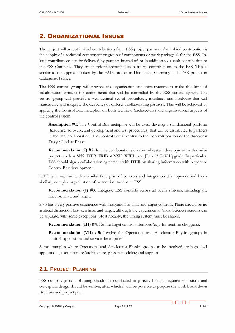
Figure 1: planned staffing level for the Integrated Control System (ICS) throughout the
construction part of the SNS project.
The planned staffing levels for the SNS are displayed in Figure 1. Each project allocates their
groups in different ways, in this case ICS includes in addition to traditional "controls‖: machine
protection, personnel protection, timing, and conventional facility controls.
The yellow line shows staff starting to come on line under the Operations part of the SNS project.
The plan called for a total of 33 FTEs as SNS moved into the transition from construction to
operations, and this was meant to be the steady-state operation number. In reality, there are 38
people in the SNS control group in 2010: 1 group leader, 25 engineers, 2 post docs and 10
technicians. Five of the engineers spend approximately half their effort as team leaders. For the
technicians, 2 are on-site contractors with contracts renewed annually. As necessary, staff is
supplemented with off-site contract work to handle additional load. The difference between the
early plan and the current situation at SNS can be attributed to many accelerator upgrade and
improvement projects that followed initial SNS design, installation, and commissioning.
2.1.2. Bottom Up Planning
Once the WBS and project schedule are prepared, define and track all activities as tasks, each with a
well defined scope, time plan, team (task manager and developers) and justification as to how this
task fits into the big picture. For each task, write a document that should be a maximum of two A4
pages long, using a consistent template and providing a short task description, task goals,
dependencies, assumptions and next steps, architecture, a descriptive picture, and task outline.
Recommendation (III) #6: Prepare a Work Breakdown Structure and task schedule for
control system development.
Recommendation (III) #7: Check and regularly iterate the bottom-up plans with the initial
task plan.
These tasks fall into one of the following types: design tasks, studies and prototypes, and
implementation tasks.
This formalization helps define the scope and deliverables before the actual work is started, which
is not always the case in control system groups. This increases the focus and efficiency of the
2.Organizational Issues Released CSL-DOC-10-53451
Public Page 16 of 52 Copyright © 2010 by Cosylab
developers, usually members of the control group. As an additional benefit, defining short task
summaries enables these documents to be used as a basis to request quotes from an external
supplier who is familiar with ESS control system development and requirements.
Recommendation (III) #8: Define and track all control system development and
maintenance activities as tasks.
2.2. PROJECT MANAGEMENT SYSTEM
The SNS control group has a very positive experience of introducing a dedicated project
management system (called Controls Request Tracker at SNS) into their control group [4]. At SNS,
the system not only provides standard request tracking features, but is interfaced to the SNS
Logbook and will be interfaced to work control system, used throughout ORNL.
SNS has introduced the system after commissioning. However, since the SNS experience was very
positive, we suggest that a project management system is used from the start of project controls
development.
Some examples of project management and issue tracking systems are:
Bugzilla [5] is a "Defect Tracking System" or "Bug-Tracking System". Defect Tracking
Systems allow individual or groups of developers to keep track of outstanding bugs in their
product effectively. Pros: Bugzilla is free and has a very wide user support. Cons: it is not a
full project management system, as it focuses primarily on software bug tracking.
JIRA [6] combines issue tracking, agile project management, customizable workflow, and a
pluggable integration framework. Pros: a commercial application with good support. Cons:
it is a payable service with a licensing model that depends on a number of users. There are
discount for research institutions.
Cosy Project Manager (CPM) [7] is a scientific project management and control tool which
focuses on research institutes. Pros: tailored for control groups, used at SNS, very
customizable with full access to all the code. Cons: Installation is not free (work for
installation is charged), the tool is not widely adopted, and there is limited support.
ESS should also consider possible integration of several of these systems (e.g., CPM project reports
with Bugzilla interface for entering bug reports).
Recommendation (III) #9: Use a dedicated project management system to track all the
developments of control system group from the start of control system development.
2.3. DEVELOPMENT PROCEDURES
ESS plans to adopt a top-down approach (everything flows from the database) for controls and
physics development. This approach was attempted before, but was not carried out in full (e.g. in
SNS). At this stage, several projects (ITER, NSLS-II) are also planning to use this approach. We
propose collaboration with both projects on how to make the top down approach a success.

CSL-DOC-10-53451 Released 2.Organizational Issues
Copyright © 2010 by Cosylab Page 17 of 52 Public
The factors determining success of a top-down approach are more organizational than technical.
Nonetheless, some technical processes must achieve a suitable level of maturity to make the top-
down approach feasible – in particular, the model must be stored in a database in such a way that it
can be then be used to generate artifacts normally obtained with manual bottom-up activities (e.g.,
generation of EPICS database from the signal list). Further discussion of this topic is in Section 4.
The top-down approach introduces two significant risks to the project.
The first is frequently termed ―analysis paralysis‖: a lot of time and effort spent on planning,
analyzing and modeling, without actual prototype artifacts (executable code, configured IOCs, etc.)
being produced. With a long enough delay, management can decide to abort the top-down
approach as unproductive and just ―start coding‖, proceeding with only a full-blown bottom-up
approach.
The second is the risk of having an unrealistic development process and limited development
tool support in place that is difficult or even impossible to follow in practice, which would then be
frequently bypassed, preventing the measures necessary for the success of a top-down approach
(e.g., naming conventions and user interface guidelines) from being properly enforced.
To mitigate the two risks, we propose the following:
Recommendation (III) #10: Provide automated and convenient interface tools connecting
RDBs to EPICS configuration files. The tool should be able to generate bottom-up artifacts
from the model.
This issue is very important, so we recommend having a person (utility programmer) assigned to
develop these tools as a priority. One example is a tool for generating EPICS configuration
database files from signal list stored in the model.
Recommendation (III) #11: Distinguish between 1) development and early testing and 2)
factory acceptance at the partner institutions. The process [54] for the first option should be
straightforward (make life of developers easy, everything for development and initial testing
should be installed and be run on a single developer machine), while the second is more
stringent and acts as a local integration test by the partner institution.
2.3.1. Development Guidelines
Where possible, tools should be developed and used that automate conformance to the standard.
For example, instead of specifying a code formatting convention in a particular programming
language, a code formatting tool should be chosen and configured to fully automate this task.
Recommendation (III) #12: Launch a pilot project in ESS Control group, introducing a
prototype development process and development tools.
Recommendation (III) #13: Enforce development standards defined in a short development
guidelines document.
Recommendation (III) #14: Perform regular internal code reviews.
2.Organizational Issues Released CSL-DOC-10-53451
Public Page 18 of 52 Copyright © 2010 by Cosylab
2.3.2. Signal List
For every subsystem, a signal list should be established in a pre-defined format. It should be a part
of every subsystem’s design reviews and acceptance tests.
The signal list shall feature all the hardware I/O signals as well as any required software signals
generated by IOCs that are of interest to other subsystems or to the general ESS control system. In
principle all these signals should be logged by the central ESS control system.
The signal list should be entered into the model early in the process. In an ideal case, the signal list
document (input for design reviews) would be generated from the model, avoiding a duplicate and
error-prone work of first composing the document and then entering signals into the model.
2.3.3. Self-description
Subsystem configuration data is stored in different file formats, sometimes even in different places
(e.g. EPICS database files and PLC configuration files). We recommended that all configuration
data is stored in one place that easy to display and edit, and is under version control.
The boot-time configuration files should be generated (as much as possible) from these single-
source files.
2.3.4. Development Infrastructure
To aid development according to modern software and hardware engineering practices, the
following infrastructural services will likely be required:
At least one file server (e.g., NFS, AFS or Windows shares – SMB) to facilitate efficient file
sharing between developers, and consistent development system environment.
Recommendation (III) #15: Set up a continuous integration build server.
A continuous integration (build) server can build the full ESS controls code base, then execute
automated test suites whenever source code or a model under version control change. Nightly
builds should be executed to catch problems early in the code integration process.
Central EPICS services, such as archiving. Several instances of the archiving server might be
required (e.g., one per subsystem).
Recommendation (III) #16: Use a version control system (e.g. Subversion).
Issue tracking tool (e.g. Bugzilla). Consider integrating this system with general project
management system or use one system for both activities. (See Section 2.2)
A database (e.g., Oracle or MySQL) for storing the model. Several replicas of the database
should be available, including:
The central (production) database.
A subsystem database, shared by subsystem developers.
A developer’s database, local to the developer’s computer (e.g., to facilitate offline
development and to decouple the developer from the rest of the team when required).
CSL-DOC-10-53451 Released 2.Organizational Issues
Copyright © 2010 by Cosylab Page 19 of 52 Public
2.3.5. Quality Management
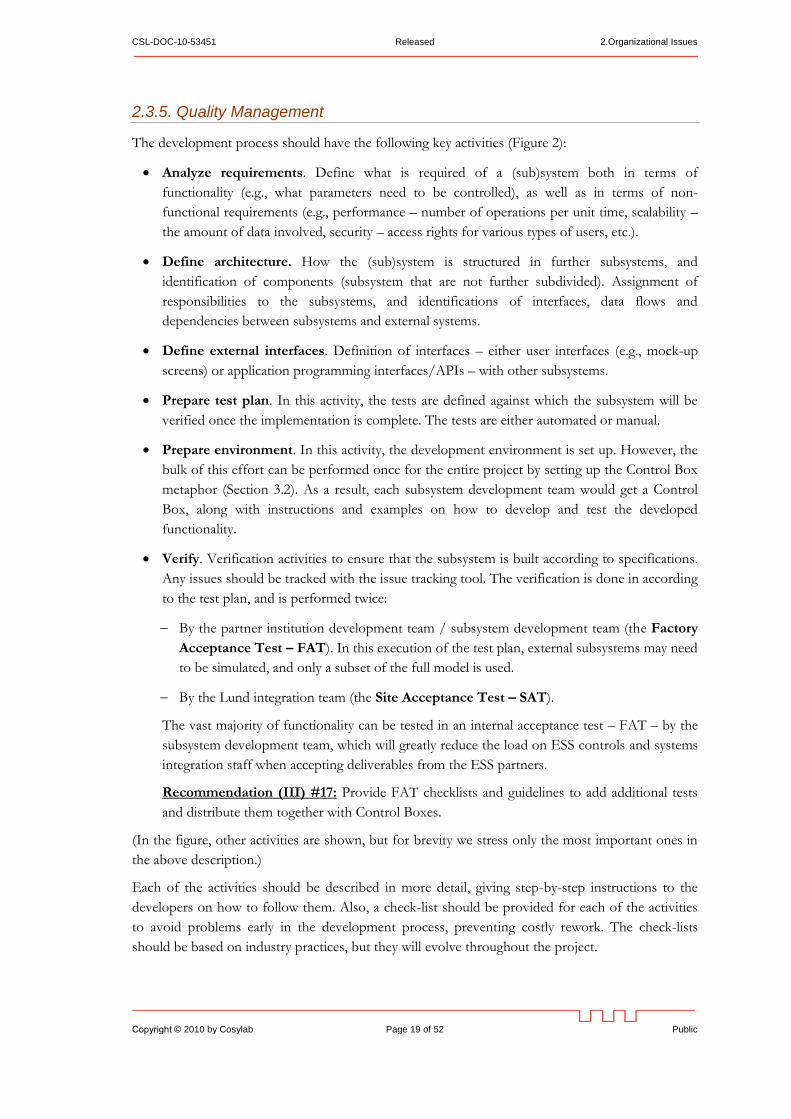
The development process should have the following key activities (Figure 2):
Analyze requirements. Define what is required of a (sub)system both in terms of
functionality (e.g., what parameters need to be controlled), as well as in terms of non-
functional requirements (e.g., performance – number of operations per unit time, scalability –
the amount of data involved, security – access rights for various types of users, etc.).
Define architecture. How the (sub)system is structured in further subsystems, and
identification of components (subsystem that are not further subdivided). Assignment of
responsibilities to the subsystems, and identifications of interfaces, data flows and
dependencies between subsystems and external systems.
Define external interfaces. Definition of interfaces – either user interfaces (e.g., mock-up
screens) or application programming interfaces/APIs – with other subsystems.
Prepare test plan. In this activity, the tests are defined against which the subsystem will be
verified once the implementation is complete. The tests are either automated or manual.
Prepare environment. In this activity, the development environment is set up. However, the
bulk of this effort can be performed once for the entire project by setting up the Control Box
metaphor (Section 3.2). As a result, each subsystem development team would get a Control
Box, along with instructions and examples on how to develop and test the developed
functionality.
Verify. Verification activities to ensure that the subsystem is built according to specifications.
Any issues should be tracked with the issue tracking tool. The verification is done in according
to the test plan, and is performed twice:
By the partner institution development team / subsystem development team (the Factory
Acceptance Test – FAT). In this execution of the test plan, external subsystems may need
to be simulated, and only a subset of the full model is used.
By the Lund integration team (the Site Acceptance Test – SAT).
The vast majority of functionality can be tested in an internal acceptance test – FAT – by the
subsystem development team, which will greatly reduce the load on ESS controls and systems
integration staff when accepting deliverables from the ESS partners.
Recommendation (III) #17: Provide FAT checklists and guidelines to add additional tests
and distribute them together with Control Boxes.
(In the figure, other activities are shown, but for brevity we stress only the most important ones in
the above description.)
Each of the activities should be described in more detail, giving step-by-step instructions to the
developers on how to follow them. Also, a check-list should be provided for each of the activities
to avoid problems early in the development process, preventing costly rework. The check-lists
should be based on industry practices, but they will evolve throughout the project.
2.Organizational Issues Released CSL-DOC-10-53451
Public Page 20 of 52 Copyright © 2010 by Cosylab
Figure 2: a possible development process workflow.
An
aly
ze
Re
qu
ire
me
nts
De
fin
e
Arc
hite
ctu
re
De
fin
e E
xte
rna
l
Inte
rfa
ce
s
Pre
pa
re T
est P
lan
Pre
pa
re
En
viro
nm
en
t
De
sig
n
Imp
lem
en
tatio
n
De
sig
n A
uto
ma
ted
Te
sts
Imp
lem
en
t
Ve
rify
Pre
pa
re L
ea
rnin
g
Pro
du
cts
Re
fin
e T
est P
lan
Re
mo
ve
De
fects
Va
lida
te a
nd
Re
lea
se
Ga
te S
PE
(exte
rna
l)
Ga
te A
RC
H
(exte
rna
l)
Ga
te D
ES
(in
tern
al)
Ga
te Q
A
(exte
rna
l)
CSL-DOC-10-53451 Released 2.Organizational Issues
Copyright © 2010 by Cosylab Page 21 of 52 Public
Wherever possible, automate verification of the check-lists, or the tool support should be such that
check-lists would be impossible to violate. For example, when defining a new signal, the naming
convention rules would be used by the signal entry tool to prevent violation of the naming
convention.
Though the depicted development process implies a waterfall-style of development, we note that
the process should be iterative and agile as well.
Recommendation (III) #18: Set up an ESS development process that is iterative and agile,
with a waterfall style of development for each iteration.
To achieve this, each subsystem would be built not in a single repetition of the depicted process,
but in several repetitions. Each repetition would address some of the functionality, in such a way
that the process can be carried out in a rather short amount of time (at most a few months).
Also, during actual construction (design and implementation activities shown in the workflow) several
intermediate releases – iterations – should be planned, so that stakeholders (e.g., the operators) can
experience the behavior early, and steer further development if needed. This way, requirements
specification phase can be less exhaustive. Also, requirements analysis is usually fairly abstract, and
attempting to be too detailed in that phase can lead to the analysis paralysis syndrome discussed above.
Recommendation (III) #19: Invite operators from other facilities (e.g., SNS) to participate
in design activities of the ESS controls.
Recommendation (III) #20: Provide a simulation framework for the ESS, along with a few
simulated operation scenarios.
During the development process, controls should strive to simulate the machine at all appropriate
levels: e.g., within the EPICS database and in XAL.
Quality management standards should be adopted to enable the iterative continuous improvement
process described above. For example, the ISO 9001 standard [50] and CMM level 5 [51] require
that the development process is continuously improved. In the proposed approach, the reported
issues would be analyzed to determine what the cause of an issue was, and based on this analysis;
check-lists would be refined.
3.Architecture Released CSL-DOC-10-53451
Public Page 22 of 52 Copyright © 2010 by Cosylab
3. ARCHITECTURE
Assumption #21: Linux will be the operating system in the service tier.
Assumption #22: ESS will use the EPICS control system.
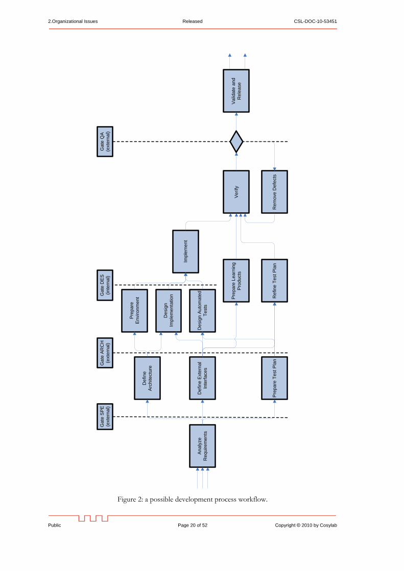
For the ESS control system, a slightly modified three-tier architecture is suitable [12]. The three
tiers, depicted in Figure 3, are:
1. User interface (upper right in the figure). These are graphical and non-graphical user
interfaces. Most of them will be in the control room, but some will be elsewhere, e.g., for site-
wide monitoring of the ESS status, and for remote access.
2. Central services (upper left in the figure). Computer services that need to run continuously
irrespective of user’s activities, e.g., for archiving of process variables’ values, monitoring of
alarm states, slow feedback loops, model of the machine as a whole, and management of
activities that require coordination of several subsystems.
3. Equipment interfaces (bottom in the figure). This tier is responsible for interaction with
equipment and devices. It serves two purposes: to provide an abstract representation of
equipment to higher layers through which the equipment can be monitored and controlled,
and to implement real-time control loops.
Equipment Interface – Control Boxes
Central RoomCentral Services
IP over Ethernet
Power Supplies Sector A
Control Box
RF Sector B
Control Box
Gatway Archive Operator’s workstation
Other networks
Model
Figure 3: a three-tier architecture of the ESS control system.
The three tiers are physically on separate computers. The characteristics of these computers on
each tier are as follows:
CSL-DOC-10-53451 Released 3.Architecture
Copyright © 2010 by Cosylab Page 23 of 52 Public
The computers of the user interface tier focus on ergonomics and usability. Examples: Apple
iMac, Microsoft Windows or a Linux distribution optimized for desktop use (e.g., Gnome or KDE
user interface).
The computers of the service tier offer high CPU performance, reliability and – depending on
purpose – have access to substantial storage capacities. Examples: HP ProLiant, Dell PowerEdge,
etc. Linux will be used as operating system of this tier.
The computers of the equipment interface tier have a wide assortment of different
input/output capabilities. The platform would likely be modular to allow various types of
input/output through field buses and custom-developed hardware. Examples: National
Instruments PXI, ATCA, VME, etc.
3.1. SCOPE OF CONTROL SYSTEM
The scope of the ESS control system is control of all equipment that is responsible for producing
and steering the beam from source to target, including all the support subsystems (vacuum, HVAC,
etc), and all the relevant control system services (archiving, alarms, compare/restore, etc).
Assumption #23: The personnel protection system (PPS) and machine protection systems
(MPS) will not be direct parts of the single controls network.
Assumption #24: All subsystems that need to take into account nuclear engineering safety
regulations are not part of the control system (e.g. target protection system).
The PPS, MPS, and other systems should be monitored through network gateways and/or
dedicated control system hardware, but this hardware should only provide read-only readbacks of
those systems’ states for archiving and correlation to other machine activity.
3.2. THE “CONTROL BOX” METAPHOR
The Control Box metaphor is based on the philosophy adopter by ITER [23]. In ITER
terminology, the Control Box philosophy is realized with the concepts Plant System Host, mini-
CODAC and plant system I&C.
The main purposes of the Control Box are to:
allow independent and yet standardized subsystem controls development,
encourage and enforce consistency between sub-systems (including target and experimental
stations),
facilitate testing of new components (e.g. EPICS drivers),
allow factory acceptance testing of subsystems through the control system,
validate technology decisions,
reduce the risks early to prevent unexpected surprises at project integration time,
3.Architecture Released CSL-DOC-10-53451
Public Page 24 of 52 Copyright © 2010 by Cosylab
force the controls group of ESS to make and document early decisions and prevent chaotic
behavior of all parties involved,
minimize throw-away hardware and software development
The Control Box hardware and software are composed of two main logical parts:
services and operator interfaces,
device control with an EPICS IOC.
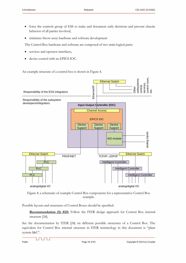
An example structure of a control box is shown in Figure 4.
Input Output Controller (IOC)
EPICS IOC
Channel Access
Device
Support
Device
Support
an
alo
g in
pu
ts
Eth
ern
et/IP
PLC
Device
Support
Intelligent Controller
Ethernet SwitchEthernet SwitchPROFINET TCP/IP, UDP/IP
PLC
PLC Intelligent Controller
Intelligent Controller
analog/digital I/O analog/digital I/O
Responsibility of the ESS integrators
Responsibility of the subsystem
developers/integrators
Ethernet Switch
Oth
er
su
bsyste
ms,
ce
ntr
al
se
rvic
es,
co
ntr
ol ro
om
,
etc
.
A/D module
Figure 4: a schematic of example Control Box components for a representative Control Box example.
Possible layouts and structures of Control Boxes should be specified.
Recommendation (I) #25: Follow the ITER design approach for Control Box internal
structure [24].
See the documentation by ITER [24] on different possible structures of a Control Box. The
equivalent for Control Box internal structure in ITER terminology in this document is ―plant
system I&C‖.
CSL-DOC-10-53451 Released 3.Architecture
Copyright © 2010 by Cosylab Page 25 of 52 Public
A generic Control Box consists of:
One or more input/output controller (IOC) computers.
Zero or more I/O modules (analog-digital converters and digitizers, digital-analog converters,
serial interfaces, etc.) attached to the IOC computer’s hardware bus.
Software:
A real-time or non-real-time operating system, depending on requirements on IOC
processing. For example, IOC real-time control loops require an IOC real-time operating
system.
The EPICS real-time database which maintains the values of all process variables under
responsibility of the IOC.
EPICS device support, which implements drivers for communication with equipment.
EPICS Channel Access, which allows the process variables on the Control Box to be
accessed from other computers in the network, and can retrieve values of process variables
from other IOCs.
PLC subsystems for slow industrial controls (e.g., water cooling; HVAC, etc) are connected to
the IOC with one of several standard communication mechanisms, such as PROFINET or
Modbus TCP/IP.
We recommend use of an Ethernet-based bus. This way, the same kind of cabling and
switching equipment that is used for other networks is also used for PLCs. Furthermore,
the PLC network is easier to connect to the IOC, as a regular network interface card and
associated drivers are used instead of a special-purpose PLC bus adapter.
Control of a large number of PLC devices may require an Ethernet switch.
We recommend use of a separate network for PLCs, so the PLC network traffic is
predictable. Otherwise, network traffic could interfere with operation of the PLCs, which
are in some cases safety-critical.
Intelligent special-purpose controllers (e.g., possibly LLRF controllers).
3.2.1. Control Box of Complex Subsystems
In the simplest case, all controlled equipment of a subsystem is located close to the control box, so
that the control box’s instrumentation can be directly connected to the equipment with signal
cables. Such an example might be the ion source and the chopper line, both located at the linac’s
front end.
In a more complex case, the equipment covers a wider geographical area. For example, the
numerous SC cavities, with their associated klystrons and cryo-modules, will be spread along almost
the entire linac. In this case, it would be impractical to control them with a single control box.
Thus for each section of length along the linac, we propose to have one control box for each type
of equipment. This control box distribution should be optimized between performance,
complexity, and cost.
3.Architecture Released CSL-DOC-10-53451
Public Page 26 of 52 Copyright © 2010 by Cosylab
For one-of-a-kind subsystems (e.g., the beam injector), there should be a single control box.
3.2.2. Control Box Development
The Control Box should not be completely defined and developed too early in the project, as the
technology landscape to support it is rapidly evolving. We therefore recommend iterative Control
Box development.
Recommendation (I) #26: Develop Control Box software and hardware in (e.g., yearly)
cycles. The main strategy is to start with software-only aspects (which are easiest to develop,
test and distribute), and as soon as possible deliver a Control Box with a simple standardized
hardware interface, such as infrastructure PLC control.
In the future versions, functionality will be added (e.g. hardware support, including timing and feed-
forward), and tools and support will evolve with available technology.
3.3. EQUIPMENT INTERFACE
This section represents the main concepts involved in interfacing hardware equipment to the ESS
control system.
Partitioning of the system into subsystems is very important. It is best to separate the control
system in subsystems that are closed entities and can be assigned to one vendor, either to an
internal team, collaborating institute or to a commercial company (e.g., for the vacuum subsystem).
The Control Box metaphor assures that these systems are treated separately (e.g. not sharing
hardware interface units). This implies that strict guidelines for their development must be
provided. This will enable clear division of responsibilities and makes integration much easier,
particularly for a project with distributed subsystem development such as ESS.
There are two types of an equipment interface, hard real-time equipment interfaces and non real-
time equipment interfaces.
A hard real-time equipment interface is needed whenever the Control Box must to respond in
hard real-time to external events. Recent experience at other facilities indicates that a hard real-time
equipment interface is needed only in the minority of cases, because specialized hard real-time
subsystems and intelligent special-purpose controllers already address the real-time aspects of
control. For example, LLRF hardware will already close real-time control loops. However, when
hard real-time is needed, a real-time operating system must be used on the IOC, or the functionality
must be implemented in hardware (e.g., FPGA).
Most of the equipment will not require a real-time interface to the control system, as it will not be
involved in distributed real-time feedback loops.
Recommendation (I) #27: Propagate real-time information between subsystems only by
means of the timing system, i.e. no other real-time communication should propagate between
different subsystems.
CSL-DOC-10-53451 Released 3.Architecture
Copyright © 2010 by Cosylab Page 27 of 52 Public
Following this recommendation isolates all aspects of subsystem real-time behavior to those
subsystems. They can then be developed and fully tested earlier in the process, during factory
testing and acceptance (Section 2.3.5), rather than later site testing, acceptance, and integration.
A non real-time equipment interface has limited responsibility for making process variables and
parameters of hard real-time control loops available to other subsystems and user interfaces.
Some equipment has its own real-time control (e.g., PLC systems, temperature regulation, motion
controllers, LLRF fast control feedback loops, etc.). Here the control system only needs to slowly
control the parameters of these low-level control loops and monitor their diagnostics (e.g.,
monitoring of PLC registers, setting reference temperature, manipulation of PID control loop
parameters, etc.).
Some equipment needs to exhibit real-time behavior, but can be controlled in a feed-forward
manner (e.g., high-level control of the superconducting RF). In this case, the control system
distributes the information on what actions to take (e.g., waveforms defining value of setpoints as a
function of time), and the timing system (see section 5.1) distributes the time and event triggers.
3.3.1. I/O Interfaces
We recommend reducing the number of different I/O types to minimize the required driver
development and maintenance.
Recommendation (VII) #28: Select one standard bus architecture with standardized I/O
modules.
Examples of I/O modules:
Time receiver module for providing synchronized time across the entire facility for time-
stamping of acquired values and synchronizing time-critical activities. (See Section 5.)
Ethernet for main control system integration and interfacing of network attached devices
(interfacing also serial or GPIB devices and instruments via RS-232 or GPIB to Ethernet
converters); this also includes read-only interface to safety and equipment protection systems
Analog and digital I/O, e.g. for power supply readback.
Digitizers of various sample rates and precision, e.g. digital oscilloscopes, spectrum analyzers,
and other high-bandwidth devices.
3.3.2. Hardware Platforms
There are three main candidates for a general control system IOC platform: VME, ATCA, PCI, and
their derivatives. In the table below we qualitatively summarize their principal characteristics
according to the following, and rank them relative to each other:
Vendor support: how many commercial vendors of crates and modules exist? A large
number implies that the probability of finding an off-the-shelf module for a particular task is
larger. Also, a notion on the trend of vendor support is given.
3.Architecture Released CSL-DOC-10-53451
Public Page 28 of 52 Copyright © 2010 by Cosylab
Maturity: how long has the platform has been available and how frequently it is used? Greater
maturity implies lower risk and lower probability of backward-incompatible changes in the
future.
Longevity: how long is the platform expected to be available? Assessment is given with the
ESS’s lifetime (several decades) in mind.
Maximum transfer rate: how much data can the platform transport between the modules in
a given time? This is a measure of performance, implying both throughput as well as latency.
Topology: how can the modules interact with each other? Master-slaves means one master
module orchestrates communication with other modules (slaves), and slaves do not directly
interacting with each other. In case of ATCA, the topologies are:
Star: each module is connected to a central hub. Modules can interact directly with one
another via this central hub. In case of Gigabit Ethernet backplane, the central hub is very
similar in function to an Ethernet switch.
Dual star: the central hub is duplicated, and each module is connected to both hubs. This
provides redundancy in case of hub or link failure.
Full mesh: each module is directly connected (point-to-point) to every other module.
Form factor: how large is the physical size of a module, in terms of the module’s height in a
rack? Larger form factor allows more I/O points on the module, but also increases the
amount of rack space that is unused for non-I/O modules.
High availability: how suitable is the platform for high-availability applications? (e.g.,
support for redundancy).
Software support: how likely will software support (Linux driver, EPICS device support) will
be available for a module.
Cost: ranking relative to the cost of the crate and modules.
Users: number of accelerator controls users that have adopted the platform.

CSL-DOC-10-53451 Released 3.Architecture
Copyright © 2010 by Cosylab Page 29 of 52 Public
VME ATCA PCI1
Vendor support
High/Declining Low/Growing Medium/Stable
3 2 1
Maturity
High Medium High
1 2 1
Longevity
Medium High High
2 1 1
Max. transfer rate
VME: 40MB/s
VME64: 80MB/s
VME64x: 160MB/s
VME320: 320MB/s
1Gbps, 10Gbps
(Gigabit Ethernet);
250MB/s/lane
(PCIe)
PCI: 133MB/s
PCIe: 250MB/s/lane
(up to 16 lanes)
2 1 1
Topology Master-slaves
Star
Dual star
Full mesh
Master-slaves
Form factor 6U (64 bit)
3U (32 bit)
12U (ATCA)
2U (μTCA) 3U
High availability
Medium High Medium
2 1 2
Software support High Medium Medium
1 PXI, a PCI extension for instrumentation, is being used at CERN, LANL, ORNL and many other accelerators, such
as for instrumentation, test and measurements among the selected platforms at ITER). PXI is an open industry
standard, modular and rugged, and leverages COTS with built-in timing and synchronization.
3.Architecture Released CSL-DOC-10-53451
Public Page 30 of 52 Copyright © 2010 by Cosylab
(Linux, EPICS) 1 2 2
Cost
High High Medium
3 2 1
Users
SNS, SLS, Diamond Light
Source, …
ITER
(considering)
CERN (LHC
collimation), LANL,
ORNL, ITER (planned)
1 3 2
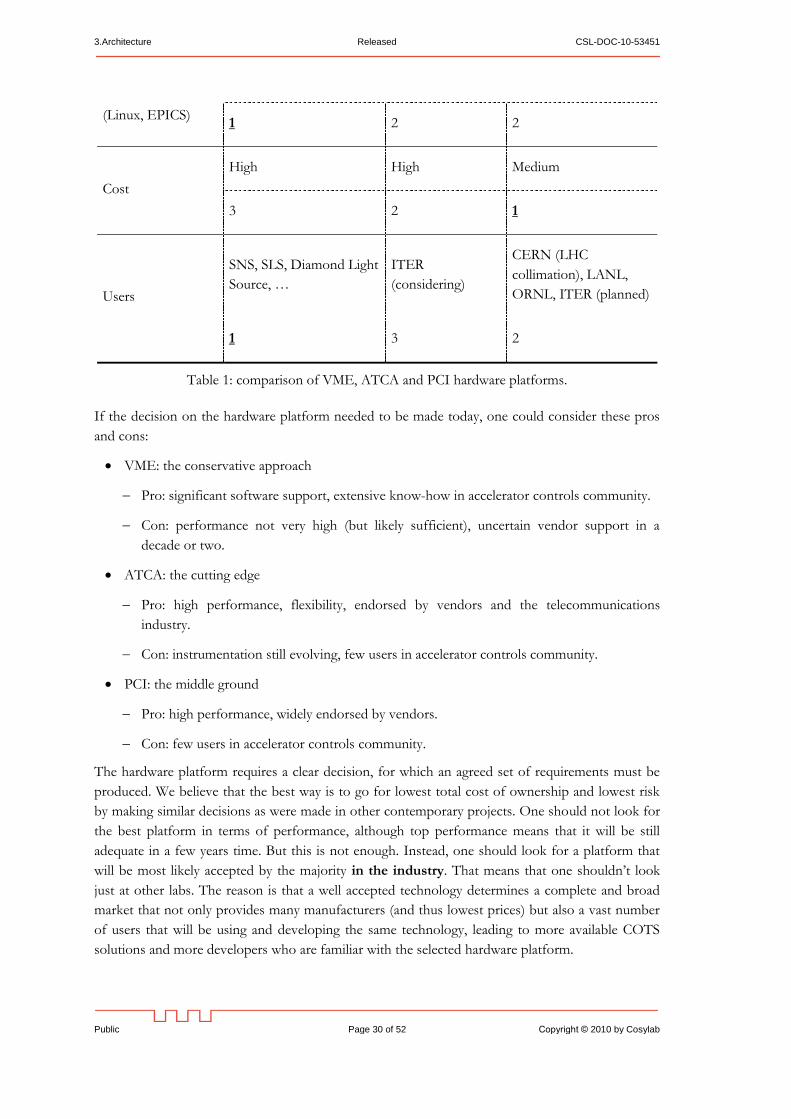
Table 1: comparison of VME, ATCA and PCI hardware platforms.
If the decision on the hardware platform needed to be made today, one could consider these pros
and cons:
VME: the conservative approach
Pro: significant software support, extensive know-how in accelerator controls community.
Con: performance not very high (but likely sufficient), uncertain vendor support in a
decade or two.
ATCA: the cutting edge
Pro: high performance, flexibility, endorsed by vendors and the telecommunications
industry.
Con: instrumentation still evolving, few users in accelerator controls community.
PCI: the middle ground
Pro: high performance, widely endorsed by vendors.
Con: few users in accelerator controls community.
The hardware platform requires a clear decision, for which an agreed set of requirements must be
produced. We believe that the best way is to go for lowest total cost of ownership and lowest risk
by making similar decisions as were made in other contemporary projects. One should not look for
the best platform in terms of performance, although top performance means that it will be still
adequate in a few years time. But this is not enough. Instead, one should look for a platform that
will be most likely accepted by the majority in the industry. That means that one shouldn’t look
just at other labs. The reason is that a well accepted technology determines a complete and broad
market that not only provides many manufacturers (and thus lowest prices) but also a vast number
of users that will be using and developing the same technology, leading to more available COTS
solutions and more developers who are familiar with the selected hardware platform.
CSL-DOC-10-53451 Released 3.Architecture
Copyright © 2010 by Cosylab Page 31 of 52 Public
Recommendation (VII) #29: Select the hardware platform after the three year milestone.
When making the decision, base it on usability (i.e. what you can do with the platform and
how well the relevant tools are debugged) and longevity (i.e. how long will it take before the
platform becomes obsolete/outdated).
3.3.3. Software Platforms
The IOC operating system might need to provide real-time performance, but this is only required
for feedback loops that span several IOCs, and these are expected to be rare: most of the fast real
time feedback loops will be developed below the level of the IOC.
Recommendation (III) #30: Evaluate the needs for real-time operating system. The key
decision criterion is how timely the application must respond: if fast reaction times are
required (less than a few milliseconds), a real-time operating system should be used.
The choice of the operating system should consider several factors. Of course, the latencies must
be sufficiently low to meet the requirements. Apart from this, the operating system should allow
management of deployed software (e.g., via a package management system), so that configuration
management of deployments is simplified. A crucial aspect of the operating system selection is
manageability of installed application software (e.g., IOCs and control system infrastructure, such as
EPICS). In particular, the operating system should have configuration management mechanisms
that support software installation, upgrades, and maintenance from a centralized location. This is an
important aspect for production where software releases need to be tightly controlled. This is also
an important aspect for development and testing, where development against an unexpected
version of software can result in unnecessary confusion and debugging efforts.
For some operating systems, EPICS is already available in form of installable packages:
For the NSLS-II project, BNL has packaged EPICS in Debian-compatible packages (DEB)
[52], primarily meant to be compatible with Debian stable distribution, but in principle also
useful for other DEB-based Linux distributions such as Ubuntu.
The ITER project has packaged EPICS in Red Hat Enterprise Linux compatible packages
(RPM). Apart from EPICS RPMs, ITER has also developed tools that allow developers to
conveniently package their applications (IOCs and operator interface screens) in installable
RPMs.
We note that packaging EPICS – and ensuring that the packaging remains in sync with the evolving
underlying operating system – requires significant effort, on the order of one person-year for initial
packaging, and 10% FTE for maintenance. Though this effort is still less than the overheads and
productivity loss when packaging is not used, we recommend leveraging of one of the above
packaging approaches for EPICS.
For production environments, an approach where the IOCs boot from a network file system is
common (e.g., SNS uses it to boot VxWorks-based IOCs). This way, central administration of all
IOCs is manageable.
However, configuration of the development environment, servers and control room workstations
must be under full centralized control, as otherwise uncontrolled changes to the environment are
easy to perform and difficult to detect.
3.Architecture Released CSL-DOC-10-53451
Public Page 32 of 52 Copyright © 2010 by Cosylab
For ESS, Mac OS is under consideration as the operating system for operators and developers,
since ESS employees have the most experience with it. However, we note that Mac OS in not
widely used as a software platform in other accelerator sites that use EPICS, which means that ESS
would need to rely mostly on its own resources if this operating system choice is extended to main
control room controls. Alternatively, ESS can use Mac hardware and use Linux distributions
mentioned above, e.g. with BootCamp, VMWare, or Parallels.
3.4. SERVICE TIER
Various software and hardware services reside in the service tier. These include both standard
internet services, such as DNS for IP lookup and NTP for computer clock synchronization, and
services specific to the control system such as web services, archiving, alarm monitoring, and online
modeling. Services are expected to be available at all times while the facility is operational, and some
should have high availability during maintenance and shutdown. Some services may require
significant processing resources or disk storage. Services should therefore reside on powerful
computing equipment, such as data center-grade servers.
We describe some of the most important services of the service tier in the following subsections.
3.4.1. Database
It is likely that a relational database management system (RDBMS)2 will be used for storing at least
some of the ESS data. Data that is suitable for storage in RDBMS includes:
Model of the facility.
Information about equipment, cabling, and other inventory.
High level machine configuration parameters. An application to review this data should be
written.
Configuration of IOCs.
Beam configurations.
Archived values of process variables3.
Operator’s log book.
Data to assist development and maintenance (project plans, issue tracking, etc.)
Documents (e.g., designs, procurement documentation, etc.)
Several RDBMS implementations exist. We recommend, however, that ESS limits the number of
different RDBMS implementations in use, to reduce the IT effort and skills required to maintain
them.
2 Even though other database technologies exist (e.g., object databases), RDBMS systems are still mainstream. We
therefore suggest that ESS also uses a RDBMS, but uses object-relational mapping techniques to store object-oriented
data. 3 EPICS already has an archiving service (EPICS Channel Archiver), which stores process variable data in binary
files, optimized for storing EPICS PVs. Therefore, an RDBMS probably won’t be used for this purpose.

CSL-DOC-10-53451 Released 3.Architecture
Copyright © 2010 by Cosylab Page 33 of 52 Public
Assumption #31: ESS will use the Oracle relational database system.
3.4.2. Alarm System
Each PV can have associated alarms in EPICS. The alarm concept is simple: when a value of a PV
is outside certain configurable bounds, EPICS raises an alarm flag associated with the PV. All
clients connected to the PV are then notified of the alarm state change.
Traditionally, the EPICS Alarm Handler OPI application is used to monitor the status of alarms.
However, this approach has several drawbacks, among them:
If the alarm handler OPI is not running, the alarms are not monitored.
If two operators wish to see the alarms, each needs to run its instance of the alarm handler
OPI, which increases the number of network connections to the IOCs.
To mitigate these drawbacks, ORNL has developed an EPICS alarm system called BEAST [53].
BEAST consists of two parts:
The alarm server.
The alarm client GUI (user interface).
The alarm server resides in the services tier. It requires several supporting services:
A Java Message Service (JMS) broker (Apache ActiveMQ implementation), which provides
infrastructure for asynchronously and reliably sending messages between processes.
A Java-based Tomcat web server for providing access to statistics about alarms.
A relational database for storing alarm transitions and acknowledgements, and for
configuration of the alarm system.
BEAST uses JMS to send notifications about alarms to the GUI, and alarm
confirmation/acknowledgement from GUI to the alarm server. Also, JMS is used for voice-based
alarm annunciation, and for logging of alarm state changes in a relational database.
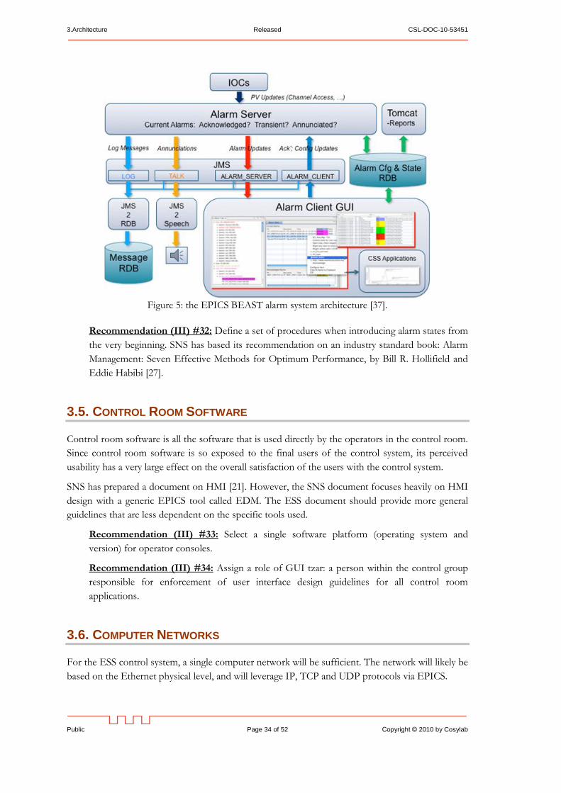
3.Architecture Released CSL-DOC-10-53451
Public Page 34 of 52 Copyright © 2010 by Cosylab
Figure 5: the EPICS BEAST alarm system architecture [37].
Recommendation (III) #32: Define a set of procedures when introducing alarm states from
the very beginning. SNS has based its recommendation on an industry standard book: Alarm
Management: Seven Effective Methods for Optimum Performance, by Bill R. Hollifield and
Eddie Habibi [27].
3.5. CONTROL ROOM SOFTWARE
Control room software is all the software that is used directly by the operators in the control room.
Since control room software is so exposed to the final users of the control system, its perceived
usability has a very large effect on the overall satisfaction of the users with the control system.
SNS has prepared a document on HMI [21]. However, the SNS document focuses heavily on HMI
design with a generic EPICS tool called EDM. The ESS document should provide more general
guidelines that are less dependent on the specific tools used.
Recommendation (III) #33: Select a single software platform (operating system and
version) for operator consoles.
Recommendation (III) #34: Assign a role of GUI tzar: a person within the control group
responsible for enforcement of user interface design guidelines for all control room
applications.
3.6. COMPUTER NETWORKS
For the ESS control system, a single computer network will be sufficient. The network will likely be
based on the Ethernet physical level, and will leverage IP, TCP and UDP protocols via EPICS.
CSL-DOC-10-53451 Released 3.Architecture
Copyright © 2010 by Cosylab Page 35 of 52 Public
The network interfaces of most computers would be 1Gbps, however some computers with large
I/O or data processing requirements may need a 10Gbps interface.
Commercial off-the-shelf switching equipment (e.g., HP’s ProCurve and Cisco’s switches) should be
sufficient to accommodate the network traffic of the ESS control system.
Topology of the controls network will probably be a star, with several levels of switches:
Edge switches for interconnecting of control boxes/equipment interfaces.
Edge switches for connecting user interface consoles in the control room.
A system of backbone switches.
Our preliminary estimate is that edge switches should have ports with at least 1Gbps capacity, and
the backbone should be implemented with 10Gbps switches. Uplinks from edge switches to the
backbone should also be over 10Gbps links.
In some cases when control boxes will be connected with sophisticated instrumentation equipment
via Ethernet, a switch will be needed between the equipment and the control box.
Physical topology should take into account two things:
1. Traffic patterns. For example, if there is intense traffic between nodes A and B, the number of
hops (switches) on the path from A to B should be minimal, and all links should be of
sufficient capacity.
2. Physical location of nodes. Switches should interconnect to nodes that are nearby. For
example, each section of the linac could have a switch.
In principle, all controls equipment could be on the same subnet. For example, if the 10.x.0.0/16
subnet is chosen, about 60.000 IPv4 addresses would be available, which should be sufficient for
ESS control needs. This would introduce fewer issues with network administration, but UDP
broadcasts would be received by all nodes on the subnet. UDP broadcasts can be minimized or
eliminated in EPICS by using a centralized naming service to locate process variables.
If several subnets are chosen, network administration issues would need to be addressed. In
particular, routing on the gateway routers would need to be properly configured, and in case
physical boundaries between subnets don’t match logical divisions, virtual local area networks
(VLANs) would need to be introduced and properly configured. Also, at least one EPICS Channel
Access Gateway [17] would then be used to allow access of process variables across subnet
boundaries. Use of the Channel Access Gateway introduces two drawbacks:
Configuration is nontrivial for cases when data communication between subnets is needed.
Additional latency occurs during data transfer, because it intermediates in the relay of all PV
data, not just during name resolution
We note that even though centralized naming server implementations exist (e.g., [14]), they should
be thoroughly tested. Additional features, such as access control, might need to be implemented;
Channel Access Gateway already provides access control.
Recommendation (III) #35: Use a single subnet and a centralized naming server instead of
UDP broadcasts for discovery of EPICS process variables.
3.Architecture Released CSL-DOC-10-53451
Public Page 36 of 52 Copyright © 2010 by Cosylab
3.7. SOFTWARE FRAMEWORKS
In this section we survey the recommended frameworks for developing control system applications.
A software framework, in computer programming, is an abstraction in which common code
providing generic functionality can be selectively overridden or specialized by user code providing
specific functionality. Frameworks are a special case of software libraries in that they are reusable
abstractions of code wrapped in a well-defined API, yet they contain some key distinguishing
features that separate them from normal libraries [32].
For each of the frameworks, we provide the scope of the framework’s applicability and emphasize
its strengths. Then we list the risks and drawbacks of the framework that are either inherent in the
framework’s architecture, or are specific to the framework’s application to ESS. Finally, we propose
what steps to take to address or mitigate these risks.
Firstly, we note that software frameworks are important and should be used, as they address non-
functional requirements, such as scalability, look & feel of the graphical user interface,
communication among distributed processes, etc. By leveraging a framework, the developers of
control system applications can focus their efforts on the functional requirements of the
application(s) they are developing, significantly improving their efficiency.
Recommendation (III) #36: Use software frameworks as a basis to develop high-level
control room applications.
3.7.1. XAL
A Java programming infrastructure for high level applications has been developed and is being used
for the Spallation Neutron Source (SNS). The framework provides a hierarchal view of the
accelerator and hides most of the underlying control system details. The hierarchy is database
configured, facilitating application sharing across different beamlines, shielding the programmer
from detailed knowledge of signal names, and allowing wholesale updating of applications. An
important part of the framework is an online model, which can be consulted for design values, live
machine values or user selected tuning values [47].
Since it is impossible to provide everything early on, flexibility is required from application
developers. This was the reason that XAL was developed: it has enabled rapid application
development of physics applications at SNS.
At its core, XAL supplies the model of the accelerator, making adaptation of the top-down model-
based approach of ESS more straightforward. Other frameworks, in particular CSS, do not (yet)
provide an accelerator physics model.
Apart from the model, XAL also provides a general-purpose application development framework,
and a suite of user interface widgets (e.g., for charting).
If possible, a single application development framework should be used. This will improve
interoperability between applications, ensure common look-and-feel across all applications, and
make development easier, as there would be no need to decide on which framework to take for a
particular application (there being only one), and developers would be able to focus on a single
application framework, improving the quality of their skill-set.
CSL-DOC-10-53451 Released 3.Architecture
Copyright © 2010 by Cosylab Page 37 of 52 Public
The widgets provided by XAL are very likely generally useful. E.g., if the application framework is
based on Eclipse Rich Client Platform of CSS (see section 3.7.2), the widgets of XAL could still be
used, even though even the graphics toolkit is different [35].
Recommendation (I) #37: Join the XAL collaboration.
Recommendation (III) #38: Use XAL for ESS physics application development
environment and participate in XAL development efforts from the beginning of ESS project.
3.7.2. Control System Studio
Control System Studio (CSS) is based on the Eclipse Rich Client Platform and is the result of a
continuing collaborative effort between DESY [33] and SNS. CSS is an environment that allows the
implementation of applications for use with control systems. Because these applications are
implemented in one environment, they present a common look and feel to the user. CSS is
designed to give facilities the ability to customize the functionality contained within the
environment by choosing the various applications or plug-ins that are included. CSS is developed
using the Eclipse development environment and is written in Java [49].
Recommendation (I) #39: Evaluate CSS for its applicability at ESS.
CSS already provides several plug-ins that provide the following user interfaces:
User interface for alarms (viewing, acknowledgement, guidance for resolving alarm
conditions).
Engineering, SCADA-style screens for subsystems (BOY and SDS plug-ins).
Viewing and editing of EPICS databases (DCT).
Monitoring of EPICS Channel Access traffic on the network.
3.7.3. Other Frameworks
The frameworks mentioned above are the most comprehensive toolkits that are presently available
for developing applications integrated with EPICS. However, there exist toolkits that cover some of
the application development needs, for example:
Qt framework [36] facilitates development of highly responsive cross-platform GUI
applications in C++. Qt is already integrated with EPICS [37].
EDM is an editor and run-time engine for engineering screens. It allows widgets to be bound
to EPICS PVs (either for monitoring values which then update the widgets dynamically, or by
setting values to the PVs). It is very responsive and allows development of screens in a short
time; however it is difficult to make good-looking and flexible screens.
3.7.4. Comparison of Software Frameworks
For each of the frameworks, we provide the scope of the framework’s applicability and emphasize
its strengths. Then we list the risks and drawbacks of the framework that are either inherent in the
3.Architecture Released CSL-DOC-10-53451
Public Page 38 of 52 Copyright © 2010 by Cosylab
framework’s architecture, or are specific to the framework’s application to ESS. Finally, we propose
what steps to take to address or mitigate these risks.
XAL:
Strengths: physics modeling, high performance GUI widgets, EPICS integration
Drawbacks: off-the-shelf application framework not leveraged, not very wide-spread
Preliminary advice: decouple physics modeling and GUI widgets from the rest of the framework
and use in the framework chosen for ESS. Join the XAL collaboration.
CSS:
Strengths: extensible user interface, large number of applications, support for engineering screens,
look&feel uniformity, EPICS integration.
Drawbacks: some plug-ins/components are duplicated (SNS and DESY version), somewhat
heavyweight if all plug-ins are installed
Preliminary advice: Choose as application framework. Decide which plug-ins are useful for ESS.
Adapt parts of XAL for CSS (physics model, GUI widgets).
Qt:
Strengths: very responsive applications, good looking user interface, consistent look-and-feel.
Drawbacks: limited use in EPICS community.
Preliminary advice: follow rate of adoption in the EPICS community.
EDM:
Strengths: very responsive, easy to compose engineering screens.
Drawbacks: technologically and aesthetically outdated, difficult to maintain look&feel.
Preliminary advice: use CSS instead.
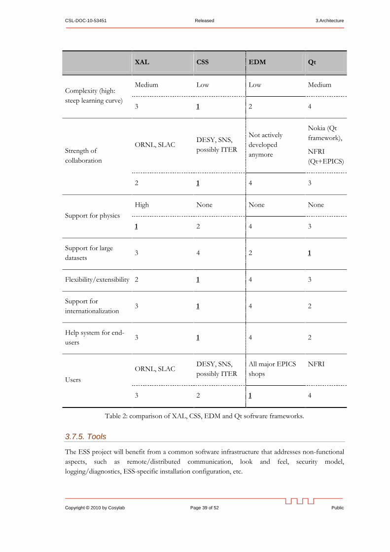
CSL-DOC-10-53451 Released 3.Architecture
Copyright © 2010 by Cosylab Page 39 of 52 Public
XAL CSS EDM Qt
Complexity (high:
steep learning curve)
Medium Low Low Medium
3 1 2 4
Strength of
collaboration
ORNL, SLAC DESY, SNS,
possibly ITER
Not actively
developed
anymore
Nokia (Qt
framework),
NFRI
(Qt+EPICS)
2 1 4 3
Support for physics
High None None None
1 2 4 3
Support for large
datasets 3 4 2 1
Flexibility/extensibility 2 1 4 3
Support for
internationalization 3 1 4 2
Help system for end-
users 3 1 4 2
Users
ORNL, SLAC DESY, SNS,
possibly ITER
All major EPICS
shops
NFRI
3 2 1 4
Table 2: comparison of XAL, CSS, EDM and Qt software frameworks.
3.7.5. Tools
The ESS project will benefit from a common software infrastructure that addresses non-functional
aspects, such as remote/distributed communication, look and feel, security model,
logging/diagnostics, ESS-specific installation configuration, etc.
3.Architecture Released CSL-DOC-10-53451
Public Page 40 of 52 Copyright © 2010 by Cosylab
Significant leverage will be obtained by choosing a common, readily available framework such as
EPICS, but ESS-specific adaptations, customizations and additions will nonetheless be required --
for example, export of TraceWin and Trace3D lattice descriptions from ESS databases.
Recommendation (III) #40: Assign a full-time tool developer position for the construction
phase.
CSL-DOC-10-53451 Released 4.Data Management
Copyright © 2010 by Cosylab Page 41 of 52 Public
4. DATA MANAGEMENT
When the ESS control system is built and integrated, it will be distributed across several hundred
control boxes, and there will be dozens of applications running in the control room and on central
servers. The control boxes will be distributed around the racks in the facility, interconnected with
numerous cables and to various kinds of equipment.
In such a large system, it is recommended that an inventory of all equipment and control points is
maintained in a central database, so that information about location and interconnectedness is
conveniently available. Such a database can be used to support the following scenarios:
1. Quickly locate a control box (e.g., because it is faulty, or it needs to be modified).
2. Determine where a certain process variable is hosted.
3. Determine where a certain process variable is used, to evaluate impacts of its change to the
rest of the system.
4. Understand avalanches of alarms by tracing connections between components in fault.
5. Obtain documentation (technical documentation, purchasing documents, installation history,
etc) associated with equipment.
6. Generate a signal list for automated archiving or logging, to support viewing and correlation of
historical settings and/or readbacks of certain process variables.
Engineering a single database solution that would support all the uses stated above is possible, but
would require significant development effort. Instead, we recommend that existing solutions are
adopted and integrated, as follows:
1. For technical, purchasing, and installation documentation, a documentation and installation
management tool (e.g., CERN's EDMS system).
2. For inventory information (process variables and their hosts), a tool such as IRMIS
3. For historical values of process variables, a tool such as EPICS Channel Archiver
In some cases, information between systems might overlap. In such cases, one of the systems
should be designated as the owner of a particular piece of information, and processes should be
developed to reliably copy this information to other systems.
4.1. BOTTOM UP VS. TOP DOWN APPROACH
In many existing controls projects, the central database/inventory was introduced late in the
project, usually to support installation or maintenance activities. Thus construction of this database
was done in a bottom-up fashion: EPICS IOCs were configured and brought together, and then
the database was populated by »reverse engineering« the installation.
However, there are several benefits if the central inventory database is introduced early in machine
design:
1. It is possible to simulate the system as a whole early, without having all the IOCs in place.
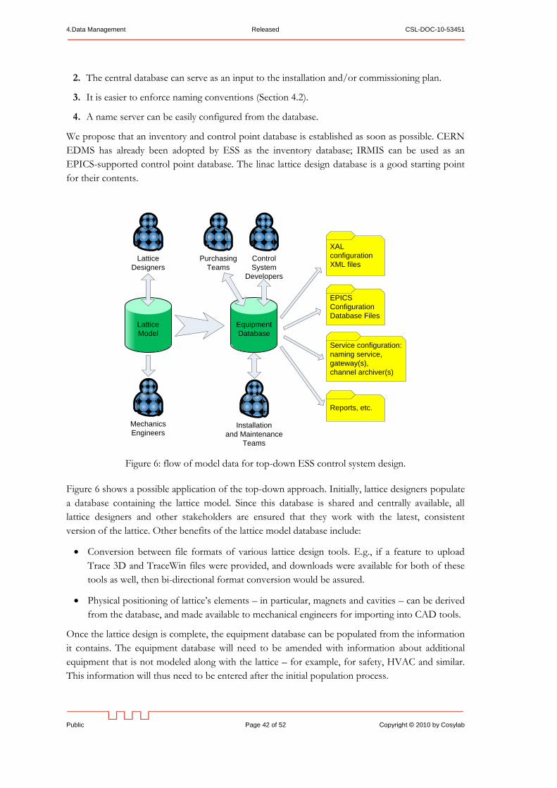
4.Data Management Released CSL-DOC-10-53451
Public Page 42 of 52 Copyright © 2010 by Cosylab
2. The central database can serve as an input to the installation and/or commissioning plan.
3. It is easier to enforce naming conventions (Section 4.2).
4. A name server can be easily configured from the database.
We propose that an inventory and control point database is established as soon as possible. CERN
EDMS has already been adopted by ESS as the inventory database; IRMIS can be used as an
EPICS-supported control point database. The linac lattice design database is a good starting point
for their contents.
Lattice
Model
Equipment
Database
XAL
configuration
XML files
EPICS
Configuration
Database Files
Lattice
Designers
Purchasing
Teams
Installation
and Maintenance
Teams
Control
System
Developers
Reports, etc.
Service configuration:
naming service,
gateway(s),
channel archiver(s)
Mechanics
Engineers
Figure 6: flow of model data for top-down ESS control system design.
Figure 6 shows a possible application of the top-down approach. Initially, lattice designers populate
a database containing the lattice model. Since this database is shared and centrally available, all
lattice designers and other stakeholders are ensured that they work with the latest, consistent
version of the lattice. Other benefits of the lattice model database include:
Conversion between file formats of various lattice design tools. E.g., if a feature to upload
Trace 3D and TraceWin files were provided, and downloads were available for both of these
tools as well, then bi-directional format conversion would be assured.
Physical positioning of lattice’s elements – in particular, magnets and cavities – can be derived
from the database, and made available to mechanical engineers for importing into CAD tools.
Once the lattice design is complete, the equipment database can be populated from the information
it contains. The equipment database will need to be amended with information about additional
equipment that is not modeled along with the lattice – for example, for safety, HVAC and similar.
This information will thus need to be entered after the initial population process.
CSL-DOC-10-53451 Released 4.Data Management
Copyright © 2010 by Cosylab Page 43 of 52 Public
An equipment database can be designed to contain all relevant information about the installed
system: what equipment is installed, where it is located, what PVs are associated with it, on which
IOC the PVs are hosted, how equipment is interconnected with cables, etc. Such a database will be
of interest to many kinds of users:
Purchasing, which would keep a list of subsystems/components that remain to be purchased,
as well as technical information (e.g., technical specification documents, test reports, etc) after
the purchase is complete. Also information such as serial numbers, delivery date, warranty
expiration date, etc., could be stored in the equipment database.
Installation and maintenance teams would enter information about where a certain equipment
is installed, who is responsible for it, and to be able to quickly find the equipment, e.g., in case
of its malfunction.
It might be that equipment database will actually consist of several integrated databases, for
example EDMS and IRMIS.
Recommendation (III) #41: Gather detailed requirements for the equipment database and
investigate existing solutions. Decide what solution(s) to use, and in case of using several
solutions, design a mechanism for keeping them in sync.
It is possible and feasible for the equipment database to contain all information related to
equipment and its control, yielding the following benefits:
A central database shared among various stakeholders (e.g., purchasing, installation teams,
maintenance teams and control teams etc.), keeping them in sync, eliminating the need for
duplicated entering of information, and reducing possibility of errors and misunderstandings.
Ability to generate most (if not all) configuration for the control system. For example, EPICS
configuration database for each IOC could be automatically generated from the equipment
model, as well as XAL configuration for physics modeling in applications and configuration of
central services (archiving, naming service, etc.).
It is possible to generate a simulation configuration for the control system, testing the
controls, operations and integrations aspects before the equipment is available.
A major risk that could sabotage the proposed top-down approach is not adhering to this approach
during development. When trust in the central equipment database erodes, the development
process naturally starts becoming bottom-up and solutions for storing partial ad-hoc information
will become necessary.
4.2. NAMING CONVENTION
Assumption #42: ESS will use EDMS [13].
Specifying naming convention, i.e. consistent naming of the elements in the facility is usually
spearheaded by the control group very early in the project. Selecting and enforcing consistent usage
of the naming convention presents a high organizational risk, because all teams, responsible for
subsystem development must conform to the convention.
4.Data Management Released CSL-DOC-10-53451
Public Page 44 of 52 Copyright © 2010 by Cosylab
In SNS, the scope of the naming convention applies to all devices (beam instrumentation, sensors,
actuators, etc.), equipment (power supplies, magnets, RF cavities, targets, moderators, instruments,
etc.) and signals in technical systems and conventional facilities. It does not apply to cable
numbering, pipe numbering, or location designations throughout the facility [28].
At PSI, the same naming standard is applied to numbering of structural elements (magnets, etc) as
well.
Recommendation (I) #43: Introduce a naming convention early in the project. There
should be a process in place that checks naming convention compliance. A person (the
naming tzar) should be assigned to address naming at the project level, and to assist control
system developers when they are in doubts on how to handle naming.
Recommendation (I) #44: Decide whether to use the same naming convention to name
control signals as well as equipment.
Recommendation (I) #45: Define the scope of EDMS usage at ESS.
Recommendation (I) #46: Use a naming convention that is consistent with EDMS.
4.3. MACHINE MODEL
There was no development loop between designing physics of the machine and XAL framework in
the case of SNS. The steps taken at SNS were:
1. Optimize the machine
2. Finish the optimization, lock it down.
3. Put the machine parameters into some database.
4. Start building the machine, make requirements for engineers (iterative process)
5. Baseline the machine design.
6. Then put everything into the db, in a global coordinate system – location of every beam line
component in the db. Add details should go into the db. Apps group defined the db structure
(not the same as XAL structure). Oracle db was used.
7. Define control interfaces (list of PVs with meanings – definitions, and units).
8. Prepare input for XAL. XAL uses XML as input. So, SNS has made a tool that generates
XML for XAL, from the db. Db is huge, different, changing, not accessible, slow to access,
which is the reason to decouple the db and XML configuration files.
CSL-DOC-10-53451 Released 5.Hard Real-Time Subsystems
Copyright © 2010 by Cosylab Page 45 of 52 Public
5. HARD REAL-TIME SUBSYSTEMS
Some subsystems of the linac will need to be controlled in hard real-time. By hard real-time we mean
a very strict deadline for the control system to respond (e.g., the end-to-end duration of a closed
control loop must have an upper bound).
With present day technology, we consider the latency threshold between real-time and non-real
time to be around 10ms4. If latencies exceed this threshold, commonly available IT equipment and
protocols can be used, such as:
Network time protocol (NTP) for time synchronization and time-stamping.
Commodity operating systems, such as widespread Linux distributions (RedHat, Ubuntu,
Fedora, Scientific Linux, …), MacOS, Windows, etc.
Network communication libraries shipped with these operating systems.
Standard personal and server computers.
Commodity network switches. Nonetheless, switches should by the very least have remote
management functionality, e.g., to keep track of configuration and allow for monitoring of
traffic statistics in order to maintain and supervise the network infrastructure.
Equipment must be more carefully chosen if hard real-time requirements must be met. In
particular, a real-time operating system, such as Linux with a real-time kernel patch, VxWorks,
LynxOS, Pharlap ETS, etc. must be used. If data flows are local (i.e., they don’t span several
computer nodes), latencies as low as 50μs can be achieved. If data flows are distributed, latencies of
500μs are still feasible.
Where timing constraints are even stricter, dedicated solutions must be adopted. In the case of ESS,
two such subsystems are:
Machine timing (see section 5.1): the activities performed by equipment across the machine
must be very tightly synchronized, and diagnostics data acquisition must be time-stamped with
high precision and accuracy.
Low-level radio frequency (LLRF, see section 5.2): Linac RF cavities will have real-time
control loops to compensate for distortion of cavity response by the passing proton bunch
train’s wakefield.
ESS might also need to adjust the machine configuration between pulses. However, the
time between two pulses – with pulse repetition rate being 20Hz and pulse duration of 1.5ms
– is 48.5ms, which allows even for the use of conventional, non-hard-real time technologies in
the majority of cases5.
4 In hard real-time, jitter and period-to-period reproducibility are actually more important criteria than the absolute
latency. However, due to nature of jitter and speed of today’s systems, the 10ms latency threshold is applicable for
most, though not all, applications. 5 If a large number of machine’s configuration parameters needs to change between pulses, the EPICSv3 control
system might have difficulties propagating the settings across the network in a timely fashion. EPICSv4, which is
currently under development, will improve on this issue by allowing batched modification of a set of PVs. Pulse to
5.Hard Real-Time Subsystems Released CSL-DOC-10-53451
Public Page 46 of 52 Copyright © 2010 by Cosylab
5.1. MACHINE TIMING
5.1.1. Overview
The role of the timing system is to synchronize receiver devices—placed all around the accelerator
facility—to perform device-specific actions just in time, relative to the passage of the beam. This is
orchestrated by means of distributing timing-system events to all timing receivers.
Assumption #47: Master clock generation is in the domain of the control group.
Master generation clock drives the injector, all LLRF clocks, and all injector and linac
instrumentation beam-synchronous triggers. This clock is by definition beam- and RF-synchronous,
and will be a multiple of the design 704 MHz primary superconducting RF frequency.
The most important parameters when defining the timing system solution are:
Number of timing receivers; this is important for estimating total cost of ownership for the
timing-system solution. Additionally, the distribution infrastructure has to be taken into
account when developing accuracy and jitter requirements.
Accuracy and jitter [8]; the timing distribution layer is to a great extent defined with these
parameters.
Patterns and decision-rules complexity level for actions that must happen in real time; this will
define the complexity of the timing master. The following questions have to be answered:
Minding power electronics requirements; how to link the operation of the accelerator with
mains and possible mechanical chopper?
Which real-time decisions have to be made; based on the present status of the machine and
all inputs? How are alternate scenarios (pre)defined?
On micro- and macro-level; how should the patterns of machine behavior be generated?
What real-time data has to be collected, processed and distributed? (GPS time, machine
protection system status, etc.)…?
5.1.2. Timing System Generic Architecture
Figure 7 illustrates a modern generic timing system solution. Any crate can be used, but he one used
should support a variety of processors and extension cards. Micro Research Finland (MRF) is
mentioned in the text as a possible transport layer; it is available in VME and cPCI form factors.
Backplane bandwidth is practically not an issue since data throughput is relatively low because the
timing master FPGA handles all real-time requirements.
pulse flexibility can also be achieved by preloading multiple pulse patterns into IOCs and switching between them
with timing triggers; a similar approach is taken at the BNL Booster and AGS.
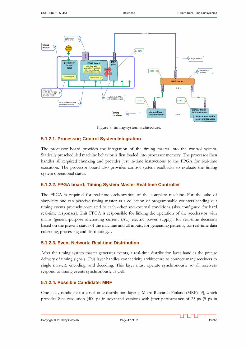
CSL-DOC-10-53451 Released 5.Hard Real-Time Subsystems
Copyright © 2010 by Cosylab Page 47 of 52 Public
Figure 7: timing-system architecture.
5.1.2.1. Processor; Control System Integration
The processor board provides the integration of the timing master into the control system.
Statically prescheduled machine behavior is first loaded into processor memory. The processor then
handles all required chunking and provides just in-time instructions to the FPGA for real-time
execution. The processor board also provides control system readbacks to evaluate the timing
system operational status.
5.1.2.2. FPGA board; Timing System Master Real-time Controller
The FPGA is required for real-time orchestration of the complete machine. For the sake of
simplicity one can perceive timing master as a collection of programmable counters sending out
timing events precisely correlated to each other and external conditions (also configured for hard
real-time responses). This FPGA is responsible for linking the operation of the accelerator with
mains (general-purpose alternating current (AC) electric power supply), for real-time decisions
based on the present status of the machine and all inputs, for generating patterns, for real-time data
collecting, processing and distributing…
5.1.2.3. Event Network; Real-time Distribution
After the timing system master generates events, a real-time distribution layer handles the precise
delivery of timing signals. This layer handles connectivity architecture to connect many receivers to
single master), encoding, and decoding. This layer must operate synchronously so all receivers
respond to timing events synchronously as well.
5.1.2.4. Possible Candidate: MRF
One likely candidate for a real-time distribution layer is Micro Research Finland (MRF) [9], which
provides 8 ns resolution (400 ps in advanced version) with jitter performance of 25 ps (5 ps in
standard form-
factor receiver
crate
MRF fanout
FPGA board
fib
er
I/F
processor
board
(SW)
configuration I/F
real-time table
execution (preloaded
list + pre-configured
conditional execution)
supervisory I/F
Eth
MRF fiber link
control system
processor for
flexible CS interface
and supervisory I/F
(to FPGA board)
GP
IOs
mains sync,
MPS, GPS...
FPGA for hard-real time
predictable response
fib
er
I/F
timing
master
fib
er
I/F
EL
I/F
application specific
receiver integration
standard form-
factor receiver
fib
er
I/F
EL
I/F
fiber fiber
single fiber link
hierarchy of
splitters
timing
receivers
MRF
EVG
events
?
possibility, both FPGA
cards could be merged
COTS
COTS
COTS COTS
5.Hard Real-Time Subsystems Released CSL-DOC-10-53451
Public Page 48 of 52 Copyright © 2010 by Cosylab
advanced version). A short high-level overview can be found in [10]. Regarding its suitability three
scenarios exist;
1. MRF is a good match in terms of price/performance; in such a case it is highly suggested
this solution is used since tremendous amount of effort was already put invested into
solution; it is readily available as a commercial of the shelf product (COTS).
2. MRF performance considerably exceeds ESS timing needs, and a relatively large number of
receivers are needed; in such a case one might want explore the possibility of using a
custom-developed distribution layer. This would require serious amount of development
effort.
3. MRF performance fails to satisfy ESS timing needs; in such a case tremendous amount of
effort would be needed to develop distribution layer.
If it turns out that scheduling requirements are relatively modest then MRF could also host the real-
time scheduler, replacing the need for a separate FPGA board and associated support.
For SNS, MRF would be a good match in terms of price/performance for the distribution layer
(option 1). Scheduling requirements for SNS are demanding, therefore the real-time scheduler is
implemented in a separate FPGA.
5.1.2.5. Prototype
If MRF is a viable solution, we propose a prototype solution based on VME; a processor board
(with Linux or RTEMS and EPICS), VME-EVG-230 (VME Event Generator with the biggest
FPGA) and couple of VME receivers (VME-EVR-230). In the process ESS will learn about the
scheduling needs and thus the FPGA size requirements, which will guide further development.
ESS should also leverage the rich expertise and experience of the SNS timing master development.
Recommendation (VII) #48: Develop a custom timing master generator, based on FPGA.
Use a commercial off-the-shelf solution for the transport layer and timing receivers.
5.1.2.6. Reasons for not Directly Copying SNS Solution
There are several reasons why the SNS timing system solution should not be adopted as-is:
SNS uses separate copper wires for event link and real-time data links (RTDL). Instead, fiber
optic links should used, as they provide better reliability, jitter, bandwidth, and noise
immunity.
The SNS implementation does not address control over signal propagation delay in a
systematic manner. Instead, per-device delay trimming is required, which complicates device
development and commissioning, and also contributes to jitter.
SNS requires multiple clocks for coordination of ring, linac, and target activities, leading to a
solution that is tightly coupled with specifics of the machine design. Instead, a single clock
would be preferred.
One might consider an ―SNS event link and RTDL over-fiber upgrade‖ as a viable alternative to an
MRF distribution layer. However this will probably lead to lower performance compared to MRF.
CSL-DOC-10-53451 Released 5.Hard Real-Time Subsystems
Copyright © 2010 by Cosylab Page 49 of 52 Public
A technical description and further information about the SNS timing system is available [11].
5.2. LOW LEVEL RADIO FREQUENCY (LLRF)
Low-level RF (LLRF) control hardware and its embedded programming play a pivotal role in the
performance of an accelerator. Modern designs implement most of the signal processing in the
digital domain. This reduces the size and cost of the hardware, but places the burden of proper
operation on the programming. FPGAs (field programmable gate arrays) and communications-
grade ADCs and DACs enable sub-microsecond delays for LLRF controller feedback signals [45].
Some aspects of the LLRF real time control are too fast to be handled through the middle layer of
the control system. A dedicated subsystem should be used for LLRF control and feedback.
Assumption #49: Fast LLRF control loops are not in the scope of the control system but
interfaces to control them are.
LLRF requires fast and slow feedback loops. Fast loops (faster than 1 Hz) are usually implemented
in FPGA. SNS developed their own FPGA; see [18] and [46]. Slow loops (1 Hz or less) should be
implemented through the control system at the field bus and EPICS level.
LLRF interfaces to other systems:
Machine timing system,
Provides output and input to machine protection system.
LLRF interaction with operators and accelerator control system in SNS
In the SNS control room, feedback loop parameters are changed only by LLRF experts. Operators
can monitor the adjustments, but they do not modify them.
Tune up of the LLRF is rarely performed, the main cases where tune up is required are:
Change of a beam pulse length.
After production or accelerator physics runs. Production runs occur several times a year, after
shutdowns. Accelerator physics runs are performed typically once per month.
6.Operations and Maintenance Use Cases Released CSL-DOC-10-53451
Public Page 50 of 52 Copyright © 2010 by Cosylab
6. OPERATIONS AND MAINTENANCE USE CASES
6.1. USER ACCESS AND SECURITY
As an example, we present the approach taken by SNS. There, three types of user access are
implemented:
Chief operator: used at only one station; has all the access rights.
Accelerator operator: used at other accelerator operator stations; has restricted access to
some common functionality.
Target operator: has access right for target functionality only, uses dedicated target control
operator consoles
Recommendation (VII) #50: Ensure the control room consoles enforce accountability and
a reasonable level of security without hindering operations.
6.2. CONTROL ROOM LAYOUT
In the SNS control room, each operator station has 6 monitors and a large LCD TVs above the
station. There are 11 stations in SNS the control room:
One chief operations station
Two accelerator operator stations
Three physics / diagnostic stations
One conventional facilities station. In addition, conventional facilities use their own control
room.
One test network station
One target station
Two alarm station, with only 3 monitors per station
Recommendation (III) #51: Prepare a list of operator stations in the ESS control room.
Provide the number of stations, and their assignments. Recommended assignments for
stations are: chief operator station, accelerator operator station, physics / diagnostic station,
conventional facilities station, test station, target station, alarm station.
6.3. CONTROL ROOM APPLICATIONS
SNS has prepared a document on HMI [21]. However, the SNS document focuses heavily on HMI
design with a generic EPICS tool called EDM. The ESS document should provide more general
guidelines that are less dependent on the specific tools used.
CSL-DOC-10-53451 Released 6.Operations and Maintenance Use Cases
Copyright © 2010 by Cosylab Page 51 of 52 Public
Control room applications can be classified into groups as:
Machine physics applications
Operator screens for individual subsystems and devices
Generic control system applications (Alarm viewer, Archive viewer, etc.)
Workflow management applications (electronic log book, help and support pages)
For a comprehensive list of SNS applications, see [18].
Recommendation (III) #52: Provide a list of detailed operations use cases (e.g. machine
tuning, normal machine operation, accelerator physics run, commissioning of a new device).
Provide a list of control system tools and applications that are required by each use case. Base
the list on experience from SNS.
6.4. ANALOGUE SIGNALS
Recommendation (I) #53: Avoid all analogue signals in control room.
All the relevant signals should be provided through the control system, preferably through
appropriate analog to digital conversion so these signals may be transparently accessed and logged.
In the SNS control room, there are two types of analogue signals in the control room: oscilloscope
waveforms and video signals. These are both present because high refresh rates are required (~20
Hz) with large data rates.
The Australian Synchrotron Project uses a standard EPICS solution for displaying video in the
control room, where 15 frames per second (fps) are routinely achieved, and the bottleneck is the
IOC CPU. In the future, CPUs will be faster, thus allowing higher frame rates.
ITER has a requirement for display of video set for 30 fps. ITER is working on a dedicated system
for video that will be integrated with controls. We suggest that ITER developments are closely
followed as the results might be directly reusable for ESS.
6.5. ELECTRONIC LOG BOOK
Electronic logbooks are used by operations and support shifts at all major accelerator facilities.
They provide an organized, searchable interface to maintain a monologue of machine observations,
analysis, results, and comments.
Recommendation (VII) #54: Gather requirements for an electronic log book at ESS.
The SNS has an electronic logbook tool called eLog [42], that is functional, stable, well-supported,
and satisfies SNS electronic logbook requirements. ESS should evaluate the SNS eLog and other
existing comparable solutions before ESS installation and commissioning.
6.Operations and Maintenance Use Cases Released CSL-DOC-10-53451
Public Page 52 of 52 Copyright © 2010 by Cosylab
Appendix A. ABOUT THE DOCUMENT
During the project, the following visits and discussions occurred:
Meeting with ESS staff with a stake in control system development in Lund.
One week visit to SNS, see meeting notes [18].
One day visit to ITER.
Participation on Writing Group meetings in Paris (presentation [20]) and Geneva.
Document History
Revision Date Changed/
reviewed
Section(s) Modification
0.1 2010-02-10 Igor Verstovsek,
Klemen Zagar,
Rok Sabjan,
Joze Dedic /
Igor Verstovsek
All Verstovsek: created the document, review,
introduction, organizational issues
Dedic: timing
Sabjan: equipment access, control box
Zagar: data management
0.2 2010-02-12 Igor Verstovsek All Sent to Todd Satogata and Steve Peggs for
first review.
0.3 2010-03-21 Igor Verstovsek,
Klemen Zagar
All Incorporated comments by Todd Satogata and
Steve Peggs on version 0.2, input from visit to
SNS, wrote new text. Intermediate working
version sent to ESS.
0.4 2010-03-26 Igor Verstovsek,
Klemen Zagar /
Todd Satogata,
Steve Peggs
All Updated after feedback on version 0.3 by Todd
Satogata, and discussions with Steve Peggs
and Todd Satogata in CERN.
1.0 2010-03-31 Igor Verstovsek,
Klemen Zagar /
Todd Satogata
All Released.