Embed Size (px)
Citation preview
Transactions, SMiRT-23
Manchester, United Kingdom - August 10-14, 2015
Division V, Paper 827
EUROPEAN RESEARCH INTO COMPOSITE STEEL-CONCRETE
STRUCTURES
Bassam A Burgan1
1 Director, The Steel Construction Institute, UK
ABSTRACT
Several manufacturers of third generation nuclear reactors have made composite steel-concrete (SC)
modular construction an integral part of new nuclear power plant (NPP). Modularization using SC
structural elements speeds up construction, simplifies the attachment of equipment support points and
reduces costs. However, whist design codes were developed in Japan, South Korea and more recently
the USA, there is no code or guidance for the design of SC structures in Europe.
A major project to develop European design rules for SC structures in the format of the Eurocodes is
currently underway. The project combines reliability analysis, testing and numerical studies and
covers both the construction and in-service stages. It includes a series of large scale test programmes
dealing with member behaviour, connection behaviour (T-shaped and wall to foundation
connections), mechanical behaviour under moderate temperature thermal strains (of particular
relevance to a loss of coolant accident (LOCA) leading to heating of the reactor building structure to
180°C), and fire tests of elements loaded axially and in bending. Data generated are complemented by
nonlinear finite element analysis. Design rules will be prepared and tested through the design of a
reference diesel generator building. The paper provides an overview of this four year project and
highlights key results to date.
INTRODUCTION
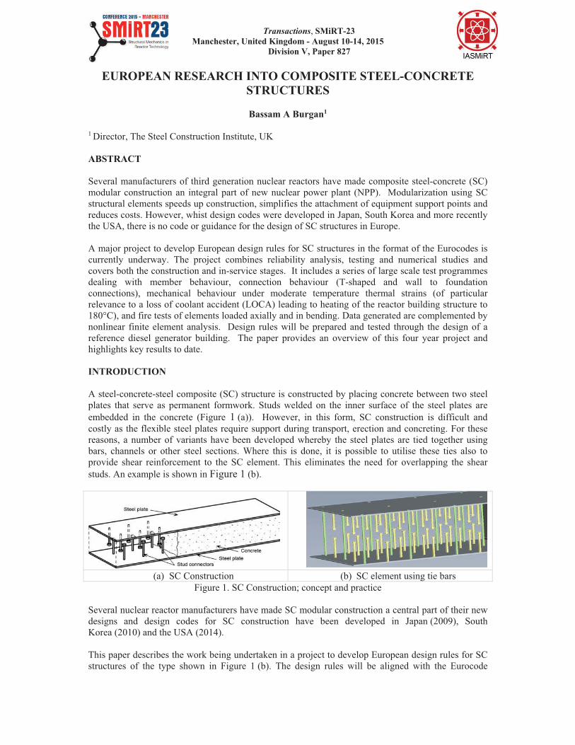
A steel-concrete-steel composite (SC) structure is constructed by placing concrete between two steel
plates that serve as permanent formwork. Studs welded on the inner surface of the steel plates are
embedded in the concrete (Figure 1 (a)). However, in this form, SC construction is difficult and
costly as the flexible steel plates require support during transport, erection and concreting. For these
reasons, a number of variants have been developed whereby the steel plates are tied together using
bars, channels or other steel sections. Where this is done, it is possible to utilise these ties also to
provide shear reinforcement to the SC element. This eliminates the need for overlapping the shear
studs. An example is shown in Figure 1 (b).
(a) SC Construction (b) SC element using tie bars
Figure 1. SC Construction; concept and practice
Several nuclear reactor manufacturers have made SC modular construction a central part of their new
designs and design codes for SC construction have been developed in Japan (2009), South
Korea (2010) and the USA (2014).
This paper describes the work being undertaken in a project to develop European design rules for SC
structures of the type shown in Figure 1 (b). The design rules will be aligned with the Eurocode
23rd Conference on Structural Mechanics in Reactor Technology
Manchester, United Kingdom - August 10-14, 2015
Division V
family of design standards. The project started in July 2013 and is scheduled for completion in
March 2017. This paper gives an overview of the project and presents some preliminary results.
REFERENCE BUILDING DESIGN
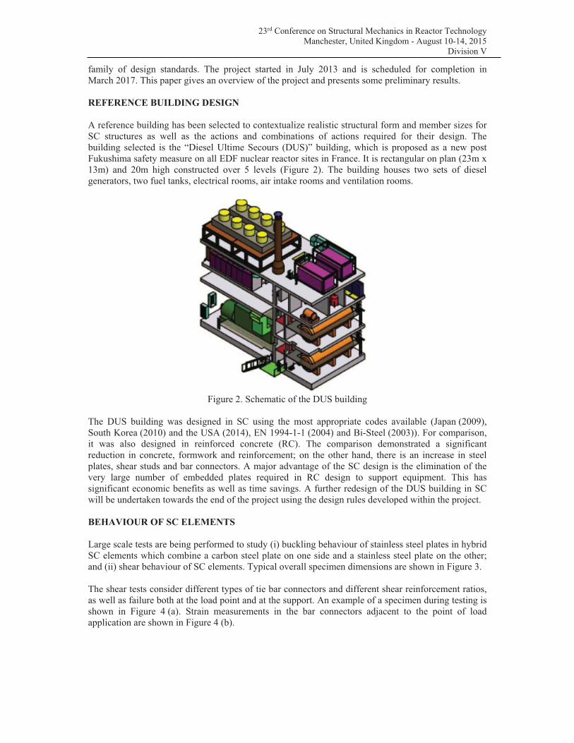
A reference building has been selected to contextualize realistic structural form and member sizes for
SC structures as well as the actions and combinations of actions required for their design. The
building selected is the “Diesel Ultime Secours (DUS)” building, which is proposed as a new post
Fukushima safety measure on all EDF nuclear reactor sites in France. It is rectangular on plan (23m x
13m) and 20m high constructed over 5 levels (Figure 2). The building houses two sets of diesel
generators, two fuel tanks, electrical rooms, air intake rooms and ventilation rooms.
Figure 2. Schematic of the DUS building
The DUS building was designed in SC using the most appropriate codes available (Japan (2009),
South Korea (2010) and the USA (2014), EN 1994-1-1 (2004) and Bi-Steel (2003)). For comparison,
it was also designed in reinforced concrete (RC). The comparison demonstrated a significant
reduction in concrete, formwork and reinforcement; on the other hand, there is an increase in steel
plates, shear studs and bar connectors. A major advantage of the SC design is the elimination of the
very large number of embedded plates required in RC design to support equipment. This has
significant economic benefits as well as time savings. A further redesign of the DUS building in SC
will be undertaken towards the end of the project using the design rules developed within the project.
BEHAVIOUR OF SC ELEMENTS
Large scale tests are being performed to study (i) buckling behaviour of stainless steel plates in hybrid
SC elements which combine a carbon steel plate on one side and a stainless steel plate on the other;
and (ii) shear behaviour of SC elements. Typical overall specimen dimensions are shown in Figure 3.
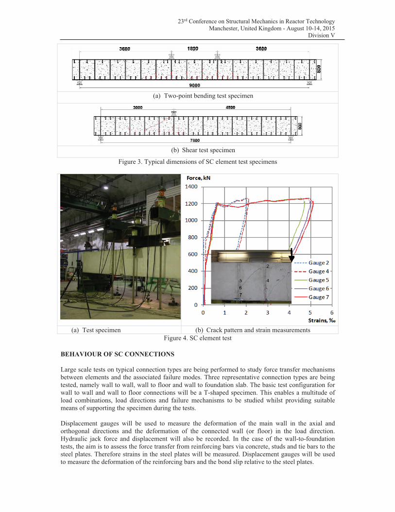
The shear tests consider different types of tie bar connectors and different shear reinforcement ratios,
as well as failure both at the load point and at the support. An example of a specimen during testing is
shown in Figure 4 (a). Strain measurements in the bar connectors adjacent to the point of load
application are shown in Figure 4 (b).
23rd Conference on Structural Mechanics in Reactor Technology
Manchester, United Kingdom - August 10-14, 2015
Division V
(a) Two-point bending test specimen
(b) Shear test specimen
Figure 3. Typical dimensions of SC element test specimens
(a) Test specimen (b) Crack pattern and strain measurements
Figure 4. SC element test
BEHAVIOUR OF SC CONNECTIONS
Large scale tests on typical connection types are being performed to study force transfer mechanisms
between elements and the associated failure modes. Three representative connection types are being
tested, namely wall to wall, wall to floor and wall to foundation slab. The basic test configuration for
wall to wall and wall to floor connections will be a T-shaped specimen. This enables a multitude of
load combinations, load directions and failure mechanisms to be studied whilst providing suitable
means of supporting the specimen during the tests.
Displacement gauges will be used to measure the deformation of the main wall in the axial and
orthogonal directions and the deformation of the connected wall (or floor) in the load direction.
Hydraulic jack force and displacement will also be recorded. In the case of the wall-to-foundation
tests, the aim is to assess the force transfer from reinforcing bars via concrete, studs and tie bars to the
steel plates. Therefore strains in the steel plates will be measured. Displacement gauges will be used
to measure the deformation of the reinforcing bars and the bond slip relative to the steel plates.
23rd Conference on Structural Mechanics in Reactor Technology
Manchester, United Kingdom - August 10-14, 2015
Division V
Wall to Wall Connections
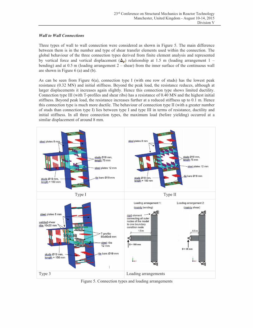
Three types of wall to wall connection were considered as shown in Figure 5. The main difference
between them is in the number and type of shear transfer elements used within the connection. The
global behaviour of the three connection types derived from finite element analysis and represented
by vertical force and vertical displacement ( ) relationship at 1.5 m (loading arrangement 1 –
bending) and at 0.5 m (loading arrangement 2 – shear) from the inner surface of the continuous wall
are shown in Figure 6 (a) and (b).
As can be seen from Figure 6(a), connection type I (with one row of studs) has the lowest peak
resistance (0.32 MN) and initial stiffness. Beyond the peak load, the resistance reduces, although at
larger displacements it increases again slightly. Hence this connection type shows limited ductility.
Connection type III (with T-profiles and shear ribs) has a resistance of 0.40 MN and the highest initial
stiffness. Beyond peak load, the resistance increases further at a reduced stiffness up to 0.1 m. Hence
this connection type is much more ductile. The behaviour of connection type II (with a greater number
of studs than connection type I) lies between type I and type III in terms of resistance, ductility and
initial stiffness. In all three connection types, the maximum load (before yielding) occurred at a
similar displacement of around 8 mm.
Type I Type II
Type 3 Loading arrangements
Figure 5. Connection types and loading arrangements
23rd Conference on Structural Mechanics in Reactor Technology
Manchester, United Kingdom - August 10-14, 2015
Division V
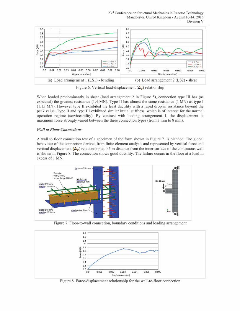
(a) Load arrangement 1 (LS1) - bending (b) Load arrangement 2 (LS2) - shear
Figure 6. Vertical load-displacement ( ) relationship
When loaded predominantly in shear (load arrangement 2 in Figure 5), connection type III has (as
expected) the greatest resistance (1.4 MN). Type II has almost the same resistance (1 MN) as type I
(1.15 MN). However type II exhibited the least ductility with a rapid drop in resistance beyond the
peak value. Type II and type III exhibited similar initial stiffness, which is of interest for the normal
operation regime (serviceability). By contrast with loading arrangement 1, the displacement at
maximum force strongly varied between the three connection types (from 3 mm to 8 mm).
Wall to Floor Connections
A wall to floor connection test of a specimen of the form shown in Figure 7 is planned. The global
behaviour of the connection derived from finite element analysis and represented by vertical force and
vertical displacement ) relationship at 0.5 m distance from the inner surface of the continuous wall
is shown in Figure 8. The connection shows good ductility. The failure occurs in the floor at a load in
excess of 1 MN.
Figure 7. Floor-to-wall connection, boundary conditions and loading arrangement
Figure 8. Force-displacement relationship for the wall-to-floor connection
23rd Conference on Structural Mechanics in Reactor Technology
Manchester, United Kingdom - August 10-14, 2015
Division V
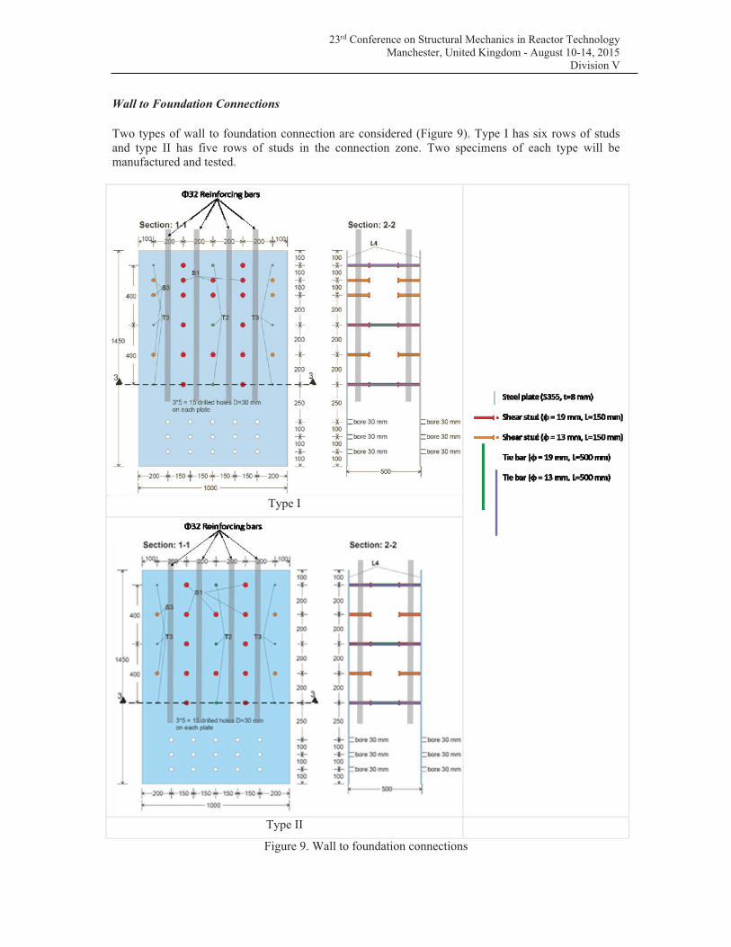
Wall to Foundation Connections
Two types of wall to foundation connection are considered (Figure 9). Type I has six rows of studs
and type II has five rows of studs in the connection zone. Two specimens of each type will be
manufactured and tested.
Type I
Type II
Figure 9. Wall to foundation connections
23rd Conference on Structural Mechanics in Reactor Technology
Manchester, United Kingdom - August 10-14, 2015
Division V
EFFECT OF MODERATE TEMPERATURE THERMAL STRAINS
The objective of this part of the project is to generate experimental data on the behaviour of SC
elements at 100 – 180°C. This is relevant to two possible accident scenarios which can lead to high
stresses in the plates due to thermal loading as the plates are constrained by the shear studs and tie
bars. This is relevant to two possible accidental events: (i) overheating in the reactor building (failure
of the steam generators) resulting in rapid temperature rise in the range of 150°C - 180°C, and (ii)
boiling water in the spent fuel building with a temperature rise to 100°C. Whilst there is limited
strength degradation of the material at the temperatures experienced, the shear studs are subjected to high
levels of strain due to expansion of the steel plate and the restraining effect of the concrete.
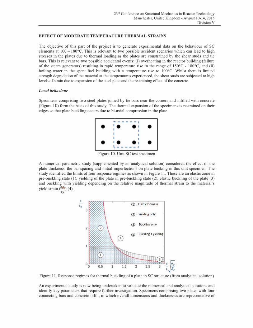
Local behaviour
Specimens comprising two steel plates joined by tie bars near the corners and infilled with concrete
(Figure 10) form the basis of this study. The thermal expansion of the specimens is restrained on their
edges so that plate buckling occurs due to bi-axial compression in the plate.
Figure 10. Unit SC test specimen
A numerical parametric study (supplemented by an analytical solution) considered the effect of the
plate thickness, the bar spacing and initial imperfections on plate bucking in this unit specimen. The
study identified the limits of four response regimes as shown in Figure 11. These are an elastic zone in
pre-buckling state (1), yielding of the plate in pre-buckling state (2), elastic buckling of the plate (3)
and buckling with yielding depending on the relative magnitude of thermal strain to the material’s
yield strain ( ) (4).
Figure 11. Response regimes for thermal buckling of a plate in SC structure (from analytical solution)
An experimental study is now being undertaken to validate the numerical and analytical solutions and
identify key parameters that require further investigation. Specimens comprising two plates with four
connecting bars and concrete infill, in which overall dimensions and thicknesses are representative of
23rd Conference on Structural Mechanics in Reactor Technology
Manchester, United Kingdom - August 10-14, 2015
Division V
full scale are used. The key variable in the experimental programme is the plate slenderness. The
following s/h ratios are considered (where s is the spacing of tie bars and h is the plate thickness):
• 83, 66, 50 are expected to buckle at temperature in the region of 200°C.
• 45 expected to buckle provided that boundary constraints are sufficiently stiff.
• 33 is expected not to buckle.
The overall size of the specimen on plan is 635 x 635 mm. Maximum plate thickness is 10 mm. The
band width between the connector and the edge of the specimen will be limited to 160 mm in order to
ensure that buckling occurs between the four connectors. A rigid steel frame is used to contain the
specimen and to prevent thermal expansion at the edges. Specimens are heated using flexible electric
heating mats and contact between plate and mats is ensured using silicone.
Global behaviour
Global thermal response will be experimentally studied using 4.8 m span beam specimens, configured
for a four-point bending test with simple supports at both ends (Figure 12).
Figure 12. General setup of a test specimen showing displacement (1) and strain (2) measurement
locations
A total 9 tests will be performed. A reference specimen will be tested at ambient temperature up to
yielding of the steel plates. Thermal tests will be performed on a replica of the reference specimen.
The temperature will be maintained for at least 12 hours to induce the evolution of bending moment
during the thermal cycle. Compression force up to 2 MPa in the concrete will be applied to the
specimen to represent the force in service.
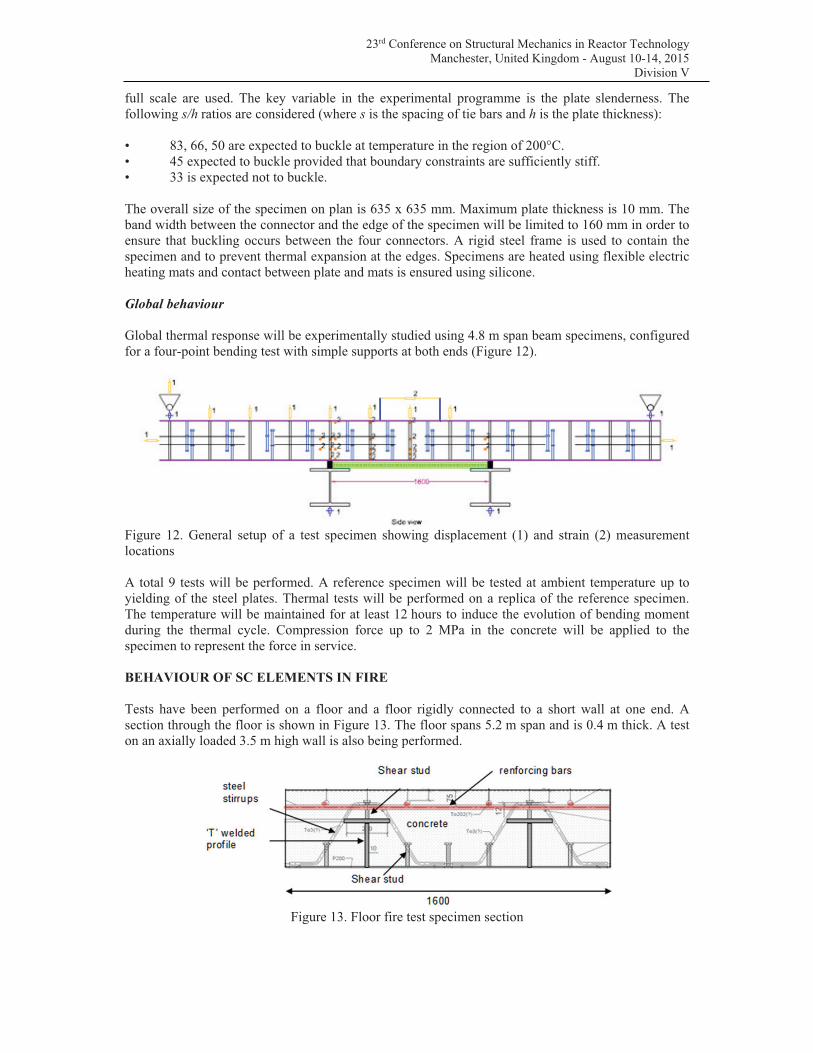
BEHAVIOUR OF SC ELEMENTS IN FIRE
Tests have been performed on a floor and a floor rigidly connected to a short wall at one end. A
section through the floor is shown in Figure 13. The floor spans 5.2 m span and is 0.4 m thick. A test
on an axially loaded 3.5 m high wall is also being performed.
Figure 13. Floor fire test specimen section
23rd Conference on Structural Mechanics in Reactor Technology
Manchester, United Kingdom - August 10-14, 2015
Division V
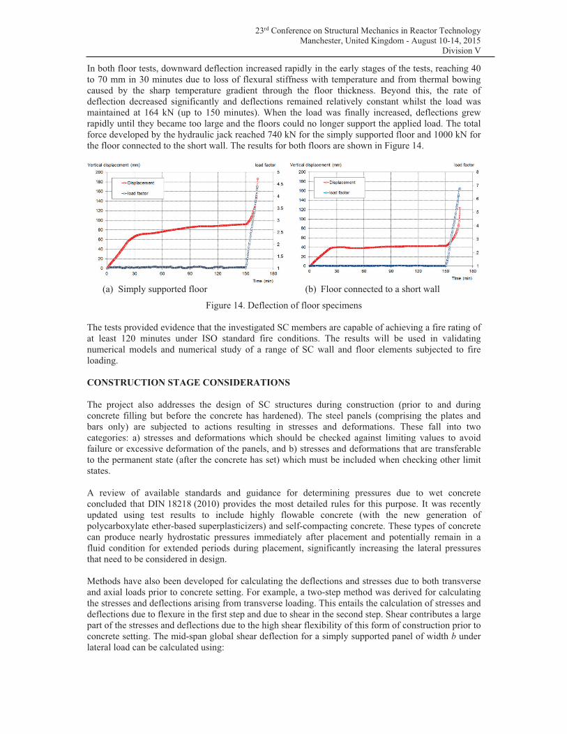
In both floor tests, downward deflection increased rapidly in the early stages of the tests, reaching 40
to 70 mm in 30 minutes due to loss of flexural stiffness with temperature and from thermal bowing
caused by the sharp temperature gradient through the floor thickness. Beyond this, the rate of
deflection decreased significantly and deflections remained relatively constant whilst the load was
maintained at 164 kN (up to 150 minutes). When the load was finally increased, deflections grew
rapidly until they became too large and the floors could no longer support the applied load. The total
force developed by the hydraulic jack reached 740 kN for the simply supported floor and 1000 kN for
the floor connected to the short wall. The results for both floors are shown in Figure 14.
(a) Simply supported floor (b) Floor connected to a short wall
Figure 14. Deflection of floor specimens
The tests provided evidence that the investigated SC members are capable of achieving a fire rating of
at least 120 minutes under ISO standard fire conditions. The results will be used in validating
numerical models and numerical study of a range of SC wall and floor elements subjected to fire
loading.
CONSTRUCTION STAGE CONSIDERATIONS
The project also addresses the design of SC structures during construction (prior to and during
concrete filling but before the concrete has hardened). The steel panels (comprising the plates and
bars only) are subjected to actions resulting in stresses and deformations. These fall into two
categories: a) stresses and deformations which should be checked against limiting values to avoid
failure or excessive deformation of the panels, and b) stresses and deformations that are transferable
to the permanent state (after the concrete has set) which must be included when checking other limit
states.
A review of available standards and guidance for determining pressures due to wet concrete
concluded that DIN 18218 (2010) provides the most detailed rules for this purpose. It was recently
updated using test results to include highly flowable concrete (with the new generation of
polycarboxylate ether-based superplasticizers) and self-compacting concrete. These types of concrete
can produce nearly hydrostatic pressures immediately after placement and potentially remain in a
fluid condition for extended periods during placement, significantly increasing the lateral pressures
that need to be considered in design.
Methods have also been developed for calculating the deflections and stresses due to both transverse
and axial loads prior to concrete setting. For example, a two-step method was derived for calculating
the stresses and deflections arising from transverse loading. This entails the calculation of stresses and
deflections due to flexure in the first step and due to shear in the second step. Shear contributes a large
part of the stresses and deflections due to the high shear flexibility of this form of construction prior to
concrete setting. The mid-span global shear deflection for a simply supported panel of width b under
lateral load can be calculated using:
23rd Conference on Structural Mechanics in Reactor Technology
Manchester, United Kingdom - August 10-14, 2015
Division V
Where is the applied load per length of panel
L is the span of the panel
Av is the shear area = b (d + t)
d is the depth of concrete
t is the thickness of steel plate
Geff is an effective shear modulus calculated using an effective width of plate equal to 20
times the plate thickness.
CONCLUSION
The paper has provided an overview of the work currently underway in a major European project to
develop design rules for SC structures. The project commenced in July 2013 and is due to be
completed in March 2017. It combines large scale tests and advanced numerical studies of elements
and connections at both ambient and elevated temperature.
When completed, the project will deliver design rules for SC structures. The application of the rules
will be illustrated by their application to the design of the DUS building.
ACKNOWLEDGEMENT
The research leading to these results has received funding from the European Union's Research Fund
for Coal and Steel (RCFS) under grant agreement no. RFSR-CT-2013-00017. The project is also
being funded by Electricité De France (EDF).
The organisations performing the technical work are The Steel Construction Institute (UK),
University of Surrey (UK), Teknologian tutkimuskeskus VTT (Finland), VTT Expert Services Ltd
(Finland), Karlsruhe Institute of Technology (Germany), SMP Ingenieure im Bauwesen GmbH
(Germany), EGIS Industries SA (France), Electricité De France (France), Ecole Normale Superieure
de Cachan (France), Ecole Speciale des Travaux Publics (France), Centre Technique Industriel de la
Construction Métallique (France), Efectis (France). The project is managed and coordinated by The
Steel Construction Institute.
REFERENCES
American Institute of Steel Construction: AISC N690s1: Specification for Safety-Related Structures
for Nuclear Facilities. Supplement No 1 (Draft dated October 1, 2014).
Bi-Steel Design and Construction Guide. Second Edition, Tata Steel (formerly Corus UK Ltd), 2003
DIN 18218:2010-01. Pressure of fresh concrete on vertical formwork.
EN 1994-1-1:2004 Eurocode 4: Design of composite steel and concrete structures: Part 1-1 General
rules and rules for buildings.
JEAC 4618-2009 Technical Code for Aseismic Design of Steel Plate Reinforced Concrete Structures.
Korea Electric Power Industries Code: SNG- Steel Plate Concrete Structures, Nuclear Structures,
2009.