Embed Size (px)
Citation preview
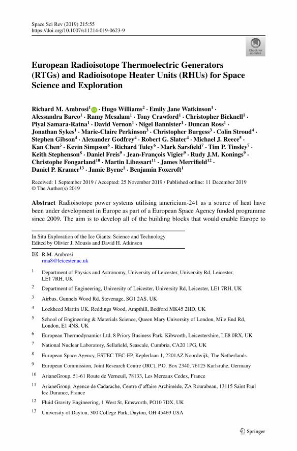
Space Sci Rev (2019) 215:55https://doi.org/10.1007/s11214-019-0623-9
European Radioisotope Thermoelectric Generators(RTGs) and Radioisotope Heater Units (RHUs) for SpaceScience and Exploration
Richard M. Ambrosi1 · Hugo Williams2 · Emily Jane Watkinson1 ·Alessandra Barco1 · Ramy Mesalam1 · Tony Crawford1 · Christopher Bicknell1 ·Piyal Samara-Ratna1 · David Vernon1 · Nigel Bannister1 · Duncan Ross1 ·Jonathan Sykes1 · Marie-Claire Perkinson3 · Christopher Burgess3 · Colin Stroud4 ·Stephen Gibson4 · Alexander Godfrey4 · Robert G. Slater4 · Michael J. Reece5 ·Kan Chen5 · Kevin Simpson6 · Richard Tuley6 · Mark Sarsfield7 · Tim P. Tinsley7 ·Keith Stephenson8 · Daniel Freis9 · Jean-François Vigier9 · Rudy J.M. Konings9 ·Christophe Fongarland10 · Martin Libessart11 · James Merrifield12 ·Daniel P. Kramer13 · Jamie Byrne1 · Benjamin Foxcroft1
Received: 1 September 2019 / Accepted: 25 November 2019 / Published online: 11 December 2019© The Author(s) 2019
Abstract Radioisotope power systems utilising americium-241 as a source of heat havebeen under development in Europe as part of a European Space Agency funded programmesince 2009. The aim is to develop all of the building blocks that would enable Europe to
In Situ Exploration of the Ice Giants: Science and TechnologyEdited by Olivier J. Mousis and David H. Atkinson
B R.M. [email protected]
1 Department of Physics and Astronomy, University of Leicester, University Rd, Leicester,LE1 7RH, UK
2 Department of Engineering, University of Leicester, University Rd, Leicester, LE1 7RH, UK
3 Airbus, Gunnels Wood Rd, Stevenage, SG1 2AS, UK
4 Lockheed Martin UK, Reddings Wood, Ampthill, Bedford MK45 2HD, UK
5 School of Engineering & Materials Science, Queen Mary University of London, Mile End Rd,London, E1 4NS, UK
6 European Thermodynamics Ltd, 8 Priory Business Park, Kibworth, Leicestershire, LE8 0RX, UK
7 National Nuclear Laboratory, Sellafield, Seascale, Cumbria, CA20 1PG, UK
8 European Space Agency, ESTEC TEC-EP, Keplerlaan 1, 2201AZ Noordwijk, The Netherlands
9 European Commission, Joint Research Centre (JRC), P.O. Box 2340, 76125 Karlsruhe, Germany
10 ArianeGroup, 51-61 Route de Verneuil, 78133, Les Mereaux Cedex, France
11 ArianeGroup, Agence de Cadarache, Centre d’affaire Archimède, ZA Rourabeau, 13115 Saint Paullez Durance, France
12 Fluid Gravity Engineering, 1 West St, Emsworth, PO10 7DX, UK
13 University of Dayton, 300 College Park, Dayton, OH 45469 USA
55 Page 2 of 41 R.M. Ambrosi et al.
launch and operate deep space and planetary missions in environments where use of solarpower or alternative power generation technologies is challenging. Although some technicaland policy work activity predate the ESA programme, the maturity of the technology hasnow reached a level that it can be incorporated in mission studies and roadmaps targeting theperiod from the mid 2020s onwards. This paper describes the state of the art in European ra-dioisotope thermoelectric generators and radioisotope heater units. This paper includes: theevolution of the technical programme in detail; descriptions of the design; evolution of RTGand RHU devices from laboratory prototypes to more advanced fully functional systems;and experimental data obtained to date. This paper also outlines the technical challengesand multidisciplinary skills required to develop what is a world leading, original, significantand transformative technology solution for planetary science and exploration missions fromthe mid 2020s onwards.
Keywords Nuclear power · Radioisotope · Space mission · Space science · Exploration
1 Introduction
1.1 Current and Historical Context
Radioisotope Thermoelectric Generators (RTGs) and Radioisotope Heater Units (RHUs) arekey enablers for exploration of outer planets, deep space and planetary surfaces (Masterset al. 2014; Arridge et al. 2014; Ambrosi et al. 2019). The historical development of RTGsand RHUs based on work carried out primarily in the USA and is described in detail inBennett (2012), Hula (2015). The culmination of the pioneering work by Ken Jordan andJohn Birden at Mound Laboratories in the early 1950s (Birden and Jordan 1959), resultedin the development the General Purpose Heat Source (GPHS) and the GPHS-RTG, whichpowered the Cassini spacecraft (Hula 2015), New Horizons (Hula 2015) and a number ofother flagship missions. More recently the GPHS has been used in the Multi-Mission RTG(MMRTG), which has been a very successful development for planetary surface applications(Hula 2015).
In order to address these challenges, Pu-238 constant-rate production was re-started inthe US with the aim of producing up to 1.5 kg per year by 2025 and the development ofhigh temperature thermoelectrics including skutterudite based (Holgate et al. 2014) and zintlbased generators (Caillat et al. 2006) has been underway for a number of years. The latter(zintls) are being considered as an option for a next-generation deep space RTG design. Inaddition, there has been some development work on reactor-based systems that would useStirling conversion systems for electrical power generation (McLure 2018).
More recently, concerns in the US programme over long-term sustainability and chal-lenges around demand for space nuclear power systems have also spurred a review of theirlaunch safety framework. This review has also focused on how to make US space nuclearpower solutions available to missions ranging from Discovery class through to Flagship mis-sions. This has resulted in the release of a Presidential memorandum encapsulating some ofthese new principles (Trump 2019).
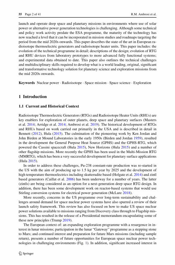
The European context of: an expanding exploration programme with a resurgence in in-terest in lunar missions; participation in the lunar “Gateway” programme as a stepping stoneto Mars; and continued interest and preparation for future Mars missions (including samplereturn), presents a number of future opportunities for European space nuclear power tech-nologies in challenging environments (Fig. 1). In addition, significant increased interest in
European Radioisotope Thermoelectric Generators (RTGs). . . Page 3 of 41 55
Fig. 1 (A) Permanently shadowed region on lunar surface with temperatures reaching 40 K as shown in (B).(C) Extensive human presence on the lunar surface planned. (D) Humans to Mars. (E) Tian surface andatmospheric probes. (F) Ice giants as future science mission targets. Images courtesy of ESA, NASA, JPL.Images from ESA are used under creative commons Creative Commons Attribution-ShareAlike 3.0 IGO(CC BY-SA 3.0 IGO)
deep space missions with the ice giants and their moons as targets (Fig. 1) also confirmsthe strategy of a European independent capability in alternatives to solar power includingradioisotope power and heat. Although a European launch safety framework is still an im-portant milestone to address in the coming years, the publication of the ESA Safety Policy onthe Use of Nuclear Power Sources (ESA 2019) and ongoing work led by France on launchsafety provides a greater degree of confidence that the launch of a European radioisotopepower system in the second half of the 2020s is achievable.
1.2 The ESA Radioisotope Power Systems Programme
Radioisotope thermoelectric generators (RTG) and radioisotope heater units (RHU) are be-ing developed in Europe as part of a European Space Agency (ESA) funded program. Thedevelopment programme led by the University of Leicester has been based on a structuredcollaboration with industry. Aimed at enabling or significantly enhancing space science andexploration missions, these systems rely on the cost-effective production of americium-241(in oxide form) for the fuel, an activity led by the National Nuclear Laboratory in the UK.The use of an iterative approach and the application of lean methodologies for the develop-ment these systems have been the focus of this technology program. Isotope containmentarchitectures and, in the case of RTG systems, bismuth telluride based thermoelectric gen-erators have been developed.
At the small end of the scale, the RHU configuration is based on a 3 W thermal poweroutput unit purely for spacecraft thermal management applications. The RHU system hasbeen designed, analysed and tested. In this paper a detailed description of the design andtest results are provided. The paper is a review of the work carried out by the authors over aperiod of 10 years and references the contextual papers already in the literature.
The RTG design and overall system architecture has evolved since the University ofLeicester began working on this project in 2010. The current RTG heat source configurationis designed to deliver between 200 W and 240 W of thermal power output (depending on the
55 Page 4 of 41 R.M. Ambrosi et al.
fuel form). A 5% total system conversion efficiency and a modular scalable design imply thatelectrical power output can range between 10 W and 50 W. Each RTG system could houseup to 5 heat sources. An electrically-heated RTG system based on the 200 W heat sourcearchitecture has been designed, analysed and tested. A detailed summary of the evolution inRTG design and outputs of the programme to date is provided in this paper.
Stirling generator power conversion technology is being developed in the UK by ThalesAlenia Space UK (Gilley et al. 2018). These systems aimed at producing around 100 W ofelectrical power per unit will not be reported in this paper as the work is being carried out iscommercially sensitive.
Launch safety studies are being led by ArianeGroup in collaboration with a range ofstakeholders in France and partners in the UK.
2 Review of Americium-241 Based Fuel Production and Consolidationfor RTGs and RHUs
2.1 Producing the Fuel
In Europe, isotope selection studies have identified 241Am as the isotope of choice forradioisotope-based systems. Americium fuel in oxide or ceramic form can be produced eco-nomically (when compared to producing 238Pu in Europe) at a high isotopic purity by usinga chemical separation method developed by the UK’s National Nuclear Laboratory to extractit from stored separated plutonium produced during the reprocessing of civil fuel (Sarsfieldet al. 2018). Spent civil reactor fuel can be reprocessed (Sarsfield et al. 2018) to extract allremaining U (mainly composed of 238U) and the Pu that has been produced. The Pu iso-topes that are extracted are separated from the U and other fission products and stored forfuture utilisation in mixed oxide fuel for power reactors. The U can flow back into the powergeneration cycle while the remaining fission products and other isotopes go into waste stor-age. Within the separated Pu, 241Am builds up as a consequence of the beta decay of 241Puwith a half-life of 14 years. The ingrowth of 241Am implies continuity of supply without therequirement to use reactors or other infrastructure for production purposes.
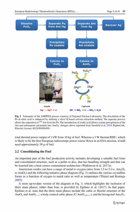
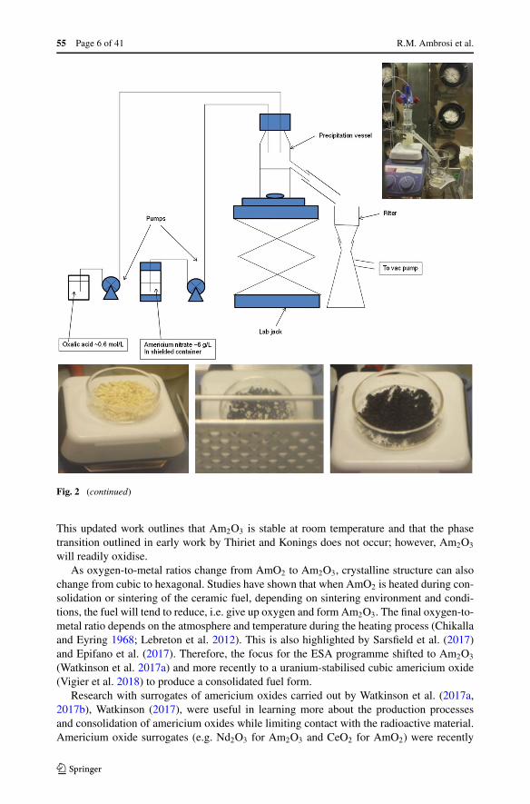
The americium and plutonium purification by extraction or AMPPEX process developedby the National Nuclear Laboratory is described in detail by Sarsfield et al. (2018) andsummarised in Fig. 2. The method for extracting the fuel is based on a silver catalyst assisteddissolution of both the Pu and Am isotopes in nitric acid, the separation of the Am whilein solution, followed by oxalate precipitation of the Am and subsequent decomposition andcalcination into an oxide ceramic powder (Sarsfield et al. 2018). It allows the separation ofthe 241Am from the separated Pu and production of the ceramic form of the fuel AmO2.The production of the ceramic fuel and development of the fuel form is led by the UK’sNational Nuclear Laboratory supported by partners including: University of Leicester andJoint Research Centre (JRC) in Karlsruhe Germany.
Properties of AmO2 (and other oxides of Am including Am2O3) include: a thermal poweroutput of ∼ 0.1 W/g; a 432-year half-life with a factor of approximately 4 reduction inpower density when compared to 238Pu based fuel used in the GPHS heat source (PuO2);and a thermal conductivity of approximately 5 W/mK reducing to about half that value forAm2O3 (Nishi et al. 2011). The melting point is around 2100 °C, although AmO2 tends todecompose at high temperatures by losing oxygen (Konings et al. 2014).
A 50 W electric RTG system, for example, could therefore require approximately 10 kgof fuel. This is based on a 5% system level conversion efficiency (Ambrosi et al. 2019) and a
European Radioisotope Thermoelectric Generators (RTGs). . . Page 5 of 41 55
Fig. 2 Schematic of the AMPPEX process courtesy of National Nuclear Laboratory. The dissolution of thePu in nitric acid is enhanced by utilising a silver II based solvent extraction method. The aqueous processallows the separation of 241Am from the Pu. The introduction of oxalic acid allows oxalate precipitation of theAm and subsequent calcination into AmO2. (Images above reprinted from Sarsfield et al. 2018; RightsLink,Elsevier License 4623650498499)
total thermal power output of 1 kW from 10 kg of fuel. Whereas a 3 W thermal RHU, whichis likely to be the first European radioisotope power source flown in an ESA mission, wouldneed approximately 30 g of fuel.
2.2 Consolidating the Fuel
An important part of the fuel production activity includes developing a suitable fuel formand consolidated structure, such as a pellet or disc, that has handling strength and that canbe inserted into a heat source containment architecture (Watkinson et al. 2017a).
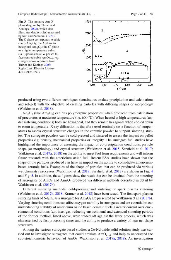
Americium oxides can have a range of metal to oxygen ratios from 1.5 to 2 (i.e. Am2O3
to AmO2) and the following tentative phase diagram (Fig. 3) outlines the various crystallineforms as a function of oxygen to metal ratio as well as temperature (Thiriet and Konings2003).
A more up-to-date version of the diagram in Fig. 3, which highlights the inclusion ofthree main phases, rather than four, is provided by Epifano et al. (2017). In that paper,Epifano et al. state that the three main phases include the cubic or fluorite structure of theAmO2 and AmO2−x ; a body centred cubic phase (C-AmO1.61+x ), and the hexagonal Am2O3.
55 Page 6 of 41 R.M. Ambrosi et al.
Fig. 2 (continued)
This updated work outlines that Am2O3 is stable at room temperature and that the phasetransition outlined in early work by Thiriet and Konings does not occur; however, Am2O3
will readily oxidise.As oxygen-to-metal ratios change from AmO2 to Am2O3, crystalline structure can also
change from cubic to hexagonal. Studies have shown that when AmO2 is heated during con-solidation or sintering of the ceramic fuel, depending on sintering environment and condi-tions, the fuel will tend to reduce, i.e. give up oxygen and form Am2O3. The final oxygen-to-metal ratio depends on the atmosphere and temperature during the heating process (Chikallaand Eyring 1968; Lebreton et al. 2012). This is also highlighted by Sarsfield et al. (2017)and Epifano et al. (2017). Therefore, the focus for the ESA programme shifted to Am2O3
(Watkinson et al. 2017a) and more recently to a uranium-stabilised cubic americium oxide(Vigier et al. 2018) to produce a consolidated fuel form.
Research with surrogates of americium oxides carried out by Watkinson et al. (2017a,2017b), Watkinson (2017), were useful in learning more about the production processesand consolidation of americium oxides while limiting contact with the radioactive material.Americium oxide surrogates (e.g. Nd2O3 for Am2O3 and CeO2 for AmO2) were recently
European Radioisotope Thermoelectric Generators (RTGs). . . Page 7 of 41 55
Fig. 3 The tentative Am-Ophase diagram by Thiriet andKonings (2003), which alsoillustrates data (circles) measuredby Sari and Zamorani (1970).The C phase corresponds to cubic(Ia-3) Am2O3; the A phase tohexagonal Am2O3; the C′ phaseto a higher temperature cubic(Ia-3) phase and all α phases toface centred cubic AmO2−(x/2) .(Images above reprinted fromThiriet and Konings 2003;RightsLink, Elsevier License4703021261997)
produced using two different techniques (continuous oxalate precipitation and calcination;and sol-gel) with the objective of creating particles with differing shapes or morphology(Watkinson et al. 2018).
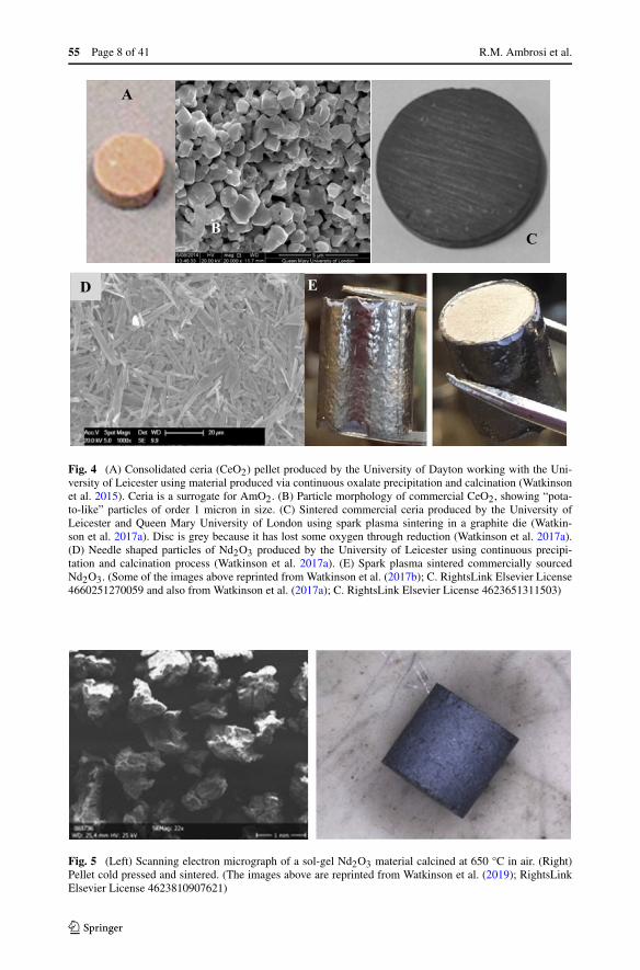
Nd2O3 (like Am2O3) exhibits polymorphic properties, when produced from calcinationof precursors at moderate temperature (i.e. 600 °C). When heated at high temperatures (un-der sintering conditions) both are hexagonal, and they remain hexagonal when cooled downto room temperature. X-ray diffraction is therefore used routinely (as a function of temper-ature) to assess crystal structure changes in the ceramic powder to support sintering stud-ies. The surrogate powders can be cold-pressed and sintered to assess the impact on pelletproperties e.g. density, mechanical properties or integrity. The surrogate fuel studies havehighlighted the importance of assessing the impact of co-precipitation conditions, particleshape (or morphology) and crystal structure (Watkinson et al. 2015; Sarsfield et al. 2017;Watkinson et al. 2017a, 2018) on the ability to meet fuel form requirements and will informfuture research with the americium oxide fuel. Recent ESA studies have shown that theshape of the particles produced can have an impact on the ability to consolidate americium-based ceramic fuels. Examples of the shape of particles that can be produced via variouswet chemistry processes (Watkinson et al. 2018; Sarsfield et al. 2017) are shown in Fig. 4and Fig. 5. In addition, these figures show the result that can be obtained from the sinteringof surrogates of AmO2 and Am2O3 produced via different methods described in detail byWatkinson et al. (2017b).
Different sintering methods: cold-pressing and sintering or spark plasma sintering(Watkinson et al. 2017b, 2018; Kramer et al. 2018) have been tested. The first spark plasmasintering trials of Nd2O3 as a surrogate for Am2O3 are presented by Watkinson et al. (2017b).Varying sintering conditions can affect oxygen mobility in surrogates and are essential to ourunderstanding stability of americium oxide based ceramic fuels. Greater control over envi-ronmental conditions (air, inert gas, reducing environment) and extended sintering periodsof the former method, listed above, were traded off against the latter process, which wascharacterised by fast processing times and the ability to produce a variety of near net shapestructures.
Among the various surrogate based studies, a Ce-Nd oxide solid solution study was car-ried out to investigate surrogates that could emulate AmO2−X and help to understand thesub-stoichiometric behaviour of AmO2 (Watkinson et al. 2017a, 2018). An investigation
55 Page 8 of 41 R.M. Ambrosi et al.
Fig. 4 (A) Consolidated ceria (CeO2) pellet produced by the University of Dayton working with the Uni-versity of Leicester using material produced via continuous oxalate precipitation and calcination (Watkinsonet al. 2015). Ceria is a surrogate for AmO2. (B) Particle morphology of commercial CeO2, showing “pota-to-like” particles of order 1 micron in size. (C) Sintered commercial ceria produced by the University ofLeicester and Queen Mary University of London using spark plasma sintering in a graphite die (Watkin-son et al. 2017a). Disc is grey because it has lost some oxygen through reduction (Watkinson et al. 2017a).(D) Needle shaped particles of Nd2O3 produced by the University of Leicester using continuous precipi-tation and calcination process (Watkinson et al. 2017a). (E) Spark plasma sintered commercially sourcedNd2O3. (Some of the images above reprinted from Watkinson et al. (2017b); C. RightsLink Elsevier License4660251270059 and also from Watkinson et al. (2017a); C. RightsLink Elsevier License 4623651311503)
Fig. 5 (Left) Scanning electron micrograph of a sol-gel Nd2O3 material calcined at 650 °C in air. (Right)Pellet cold pressed and sintered. (The images above are reprinted from Watkinson et al. (2019); RightsLinkElsevier License 4623810907621)
European Radioisotope Thermoelectric Generators (RTGs). . . Page 9 of 41 55
was conducted to identify if such a surrogate with a specified stoichiometry could be cre-ated and to understand the effect of the variables of the synthesis route on particle properties,with the objective of producing particles with a range of properties. The standard methodsof oxalate co-precipitation and subsequent thermal decomposition (calcination) were used.Numerous analytical techniques were used to verify Ce-Nd oxide solid solution productionand to characterise its composition. The effect of co-precipitation conditions (e.g. tempera-ture and stirring rate) on particle morphology and size were found to be important, as wellthe influence of the calcination process on subsequent oxide particle properties (Watkinsonet al. 2017a). Although this solid solution work is less relevant to the utilisation of Am2O3
for future ESA radioisotope power systems it is relevant to building a more comprehensivebody of knowledge related to oxides of americium and their surrogates.
More recently, in collaboration with JRC, Watkinson et al. (2019) used the sol-gel methodand oxalate-derived calcination to produce Nd2O3, and successfully sintered the powderproduced via both these routes. Other work performed by JRC Karlsruhe focused on theproduction of uranium-stabilised americium oxide ceramic in order to maintain the cubicform of americium oxide over a large range of temperature and oxygen potential, includingreductive sintering conditions. The produced ceramic had a measured specific power outputof 0.082 Wth/g. This reduced specific power is due both to introduction of uranium in theoxide and the presence of a significant amount of 237Np (daughter element of 241Am). It hasto be compared to the theoretical specific power of pure americium oxide of 0.101 Wth/gfor AmO2 and 0.104 Wth/g for Am2O3. However, despite this drawback, uranium-stabilisedamericium oxide present several advantages on the material properties: stabilisation of thefluorite like structure which have excellent behaviour under alpha self-irradiation, pelletintegrity preserved under occidental oxidizing condition improving material safety due tomaintain of cubic structure, good behaviour during sintering, good host for americium decayproduct with the neptunium integrating the material structure.
For images of americium-based pellets and further details of the consolidation work car-ried out with americium oxides, the readers are referred to Sarsfield et al. (2017, 2018) andVigier et al. (2018).
3 Developing the Heat Source for RTGs and RHUs
3.1 Heat Source Architecture
Once the fuel has been consolidated into pellets or discs, the fuel is then inserted into amultilayer containment system that is generally defined as the heat source. The containmentapproach is based on “defence in depth” with multiple layers of containment ensuring thatrisk of dispersal of the radioisotope is minimised under launch accident conditions. Con-tainment directly linked to launch safety and radiological protection is described in detail byBarco et al. (2019a), Williams et al. (2013) and the ESA Safety Policy on the Use of NuclearPower Sources (ESA 2019).
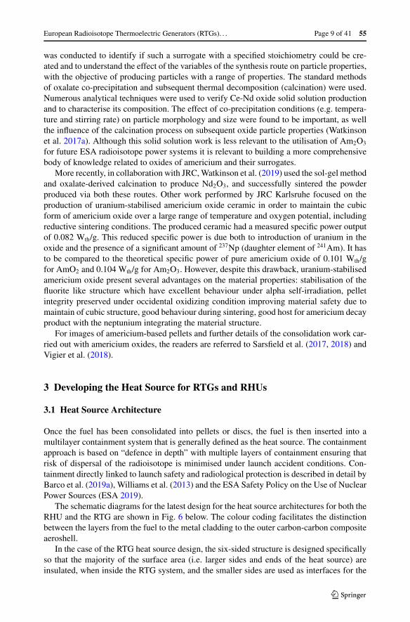
The schematic diagrams for the latest design for the heat source architectures for both theRHU and the RTG are shown in Fig. 6 below. The colour coding facilitates the distinctionbetween the layers from the fuel to the metal cladding to the outer carbon-carbon compositeaeroshell.
In the case of the RTG heat source design, the six-sided structure is designed specificallyso that the majority of the surface area (i.e. larger sides and ends of the heat source) areinsulated, when inside the RTG system, and the smaller sides are used as interfaces for the
55 Page 10 of 41 R.M. Ambrosi et al.
Fig. 6 (Top) Architecture for the RHU with colour coded elements: fuel (pink), platinum-rhodium cladding(green), insulation (orange), carbon-carbon composite aeroshell (blue). (Bottom) The latest design of the200 W thermal heat source for the RTG system that incorporates 12 fuel clads. There are 6 aeroshell sleevesto accommodate the 12 clads, 3 on each side of the aeroshell. Each sleeve accommodates 2 clads
thermoelectric generators (see Sect. 4). In addition, the six-sided structure allows the fuelto occupy the smallest volume when compared to placing all the fuel on-axis. The volumeoccupied by the fuel affects the specific power of the RTG because it drives the volume ofthe whole system.
3.2 Platinum Alloy Cladding
The first containment layer in the heat source is a cladding structure made from a platinum20%-rhodium alloy. This welded cladding structure surrounds the fuel and forms a sealedsource that can be inserted in the outer containment layer described in greater detail inSect. 3.3.
Work carried out by the Oak Ridge National Laboratory and others in the 1960s and1970s (Jaffee et al. 1961; Inouye et al. 1972) on the behaviour of candidate cladding ma-terials and metals used in cermet fuels revealed that Pt, Rh and Pt-Rh alloys less likely to
European Radioisotope Thermoelectric Generators (RTGs). . . Page 11 of 41 55
oxidise at the operating temperatures of americium-based nuclear power systems. The workoutlines that this likelihood is 4 orders of magnitude less than iridium; 7 orders of magnitudeless than tungsten, tantalum and niobium and 8 orders less than molybdenum and rhenium.These operating temperatures can range between 300 °C and 600 °C depending on whetherthe heat source is an RHU or an RTG heat source respectively.
Oxidation resistance is a driver for post-impact isotope containment capability given thatchanges to the structure of the cladding could compromise its mechanical properties; there-fore, maximising this resistance is important in the design of the inner containment. A de-tailed investigation (led by the University of Leicester in collaboration with JRC, Karlsruhe)is currently underway to assess the compatibility of Pt-Rh alloys in contact with americium-based oxide ceramics under a range of environments and will be the subject of future publi-cations.
The experimental study by Inouye et al. (1972) highlighted that Pt alloys are oxidationresistant to at least 1200 °C, with no measurable changes at this temperature after a 200-hour oxidation experiment when compared to Mo and Ta. The study also showed that theinclusion of W in Pt-Rh alloys improves strength and, contrary to the expected inverse re-lationship between strength and ductility, significantly increases ductility above 1100 °C,a property that is unique to these alloys. The presence of Hf and Ti in the alloy can increasestrength, increase recrystallisation temperature and reduce grain growth. Recrystallizationtends to reduce strength and hardness while increased grain growth lowers yield stress. Onekey element in the report by Inouye et al. (1972) highlights that toughness yield strengthsthat can exceed 80% of ultimate tensile strengths. This is important when considering thatthe cladding could be subjected to a severe impact as a consequence of a launch accident(Barco et al. 2019a).
Both Pt and Rh produce binary eutectics in the presence of carbon at around the sametemperature of ∼ 1738 ◦C (Yamada et al. 2001). This is relevant because a carbon-carboncomposite aeroshell structure surrounds the fuel clads. However, Pt-30%Rh maintains anelongation to failure greater than 30% even after exposure to graphite at 1700 °C (giving thepotential to create C-Pt and C-Rh eutectics) (Tate 1982). This elongation to failure is alsomaintained down to ambient temperatures. The phase diagram for the americium-platinumsystem is described in detail by Schulz (1976) and shows that for Pt metal there is a eutec-tic formed with americium at ∼ 1580 ◦C. Schulz also highlights that heating Am2O3 in areducing atmosphere at 1200 °C with Pt for 40 hours will produce an intermetallic with Pt(Pt5Am); this is consistent with the increased vapour pressure of Am when working withAm2O3 as opposed to AmO2 (Sarsfield et al. 2018). The work by Schulz (1976) shows thatthere is an intermetallic between Rh and Am, which forms when heating AmO2 with Rh ina reducing atmosphere at 1550 °C for 60 hours.
The referenced studies outline some of the key critical temperatures that could affect theproperties of the cladding and lead to important safety considerations. These temperaturesare being used as design drivers in the architectures of the heat sources for both the RHUand RTG being developed for ESA.
The most technically mature approach for americium-fuelled RTGs and RHUs, in termsof total number of systems launched and test data available, is to use a Pt-based alloy asa cladding layer around the fuel pellet. Pt-Rh alloys are most compatible, stable and leastreactive materials that could meet the safety requirements that have been defined as part ofthe ESA programme. These alloys offer a good starting point for developing and testing aprimary containment layer for americium systems.
The oxygen released by the americium-oxide fuel at elevated temperature, or the build-up of helium over time as a consequence of alpha decay, could pressurize the clad from
55 Page 12 of 41 R.M. Ambrosi et al.
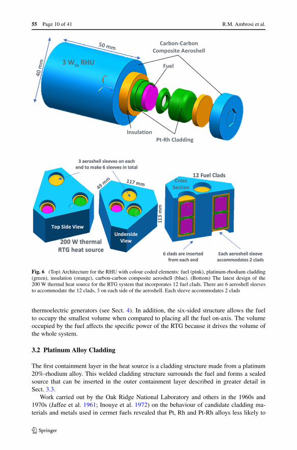
Fig. 7 General architecture of the RHU and RTG clads. One key feature is that the RTG clad is a scaled-upversion of the RHU clad which shares the frit vent design of the RHU clad
within. To avoid this pressurization, a vent hole covered by a porous frit is required in thecladding design. This allows the gases to be released and reduces the risk of the clad breach-ing (Johnson 1984). Frit vents (made of sintered pure platinum powder) for European RTGsystems are currently under development using proprietary methods being developed by theUniversity of Leicester and will be reported in the literature when results become available.To the best knowledge of the authors, platinum frit vents are not commercially available inEurope.
The general architecture for the platinum cladding structures for the RTG and RHU heatsources is provided in Fig. 7. The only differences between the RTG clad and RHU clad isthat the RTG clad has a larger diameter (32 mm outer diameter is as opposed to 20 mm forthe RHU) and length (42 mm as opposed to 32 mm for the RHU). Both are made from samealloy (Pt-20Rh), have the same wall thickness (approximately 2 mm), are machined froma solid bar to produce the net shapes, have a threaded girth seal which can be welded, andboth share the same frit vent design.
3.3 Carbon-Carbon Composite Aeroshell
Surrounding the cladding are two layers: an insulating layer and a carbon-carbon compositeaeroshell. This approach is a standard way of protecting the cladding and fuel from acci-dent conditions and is reflected in the US GPHS and light-weight radioisotope heater unit(LWRHU) designs (Hula 2015).
European Radioisotope Thermoelectric Generators (RTGs). . . Page 13 of 41 55
The layer immediately surrounding the primary containment or cladding is an insulationlayer. A compliant insulating graphitic foam is the latest baseline design. This insulationlayer prevents the cladding and fuel from exceeding specific temperatures defined in thefirst iteration of the safety requirements for a European RTG and RHU when these systemsare exposed to extreme external temperatures (see Sect. 3.3.1 and 3.4). These extreme non-operational conditions can be experienced under different accident scenarios e.g. Earth re-entry, launch-pad fires. This effect has been shown in a study by El Genk and Tournier forthe US LWRHU (El Genk and Tournier 2001).
Surrounding the cladding and the fuel is the protective ablative aeroshell material thatprovides a thermo-mechanical interface between the heat source and the thermoelectricconverters in the case of the RTG and an interface with the thermal management systemof the spacecraft in the case of the RHU. A number of 2.5D and 3D carbon-carbon com-posites were identified as options for the European RTG and RHU heat sources. Thesecomposites are available as commercial off-the-shelf products produced for aerospace ap-plications in France. Three-dimensional carbon-carbon composites are produced by ArianeGroup and grouped under the SEPCARB® (Lacoste et al. 2002) registered product name.The SEPCARB® family of composites are the baseline for the ESA RTG and RHU heatsource aeroshells. Both 2.5D and 3D grades of materials produced by Mersen in Francelisted as A035 and AM252 (Mersen 2019) have been evaluated.
Thermal and mechanical modelling of the heat sources has been carried out by Barcoet al. (2019b). The performance of the aeroshell materials under Earth re-entry accidentconditions has been simulated and are summarised below.
3.3.1 Earth Re-Entry Heating Simulation of Aeroshell Materials
In 1957, Allen and Eggers (1957) studied the motion and heating of ballistic missiles enter-ing the Earth’s atmosphere at supersonic speeds. From their study, they derived a multitudeof analytical equations, which could be applied to a broad range of re-entry scenarios. Fol-lowing this work, a number of authors developed simplified expression for stagnation pointaerothermal heating including: Fay and Riddell (1958), Detra and Hidalgo (1961) and, morerecently, Brandis and Johnston (2014). Putnam and Braun (2015) revisited the Allen andEggers analytical solutions and produced an extended and enhanced version. This extendedand enhanced version can be applied to atmospheric re-entry scenarios for RTGs and RHUs;allowing the velocity, V , the acceleration magnitude, a, and the convective heat flux, Q, tobe calculated at the stagnation point for any stage in the descent.
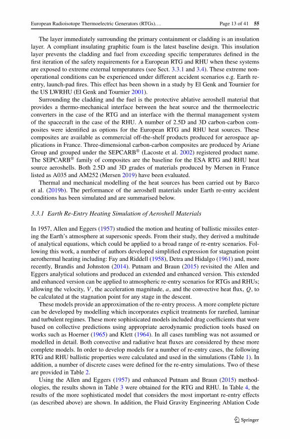
These models provide an approximation of the re-entry process. A more complete picturecan be developed by modelling which incorporates explicit treatments for rarefied, laminarand turbulent regimes. These more sophisticated models included drag coefficients that werebased on collective predictions using appropriate aerodynamic prediction tools based onworks such as Hoerner (1965) and Klett (1964). In all cases tumbling was not assumed ormodelled in detail. Both convective and radiative heat fluxes are considered by these morecomplete models. In order to develop models for a number of re-entry cases, the followingRTG and RHU ballistic properties were calculated and used in the simulations (Table 1). Inaddition, a number of discrete cases were defined for the re-entry simulations. Two of theseare provided in Table 2.
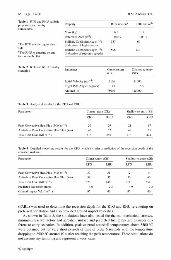
Using the Allen and Eggers (1957) and enhanced Putnam and Braun (2015) method-ologies, the results shown in Table 3 were obtained for the RTG and RHU. In Table 4, theresults of the more sophisticated model that considers the most important re-entry effects(as described above) are shown. In addition, the Fluid Gravity Engineering Ablation Code
55 Page 14 of 41 R.M. Ambrosi et al.
Table 1 RTG and RHU ballisticproperties for re-entrysimulations
aThe RTG re-entering on shortsidebThe RHU re-entering on endface or on the flat
Property RTG side ona RHU end onb
Mass (kg) 6.1 0.17
Reference Area (m2) 0.019 0.0014
Ballistic Coefficient (kg m−2)(indicative of high speeds)
337 66
Ballistic Coefficient (kg m−2)(indicative of subsonic speeds)
598 133
Table 2 RTG and RHU re-entryscenarios Parameter Comet return
(CR)Shallow re-entry(SE)
Initial Velocity (ms−1) 12106 11000
Flight Path Angle (degrees) −11 −6.5
Altitude (m) 78000 125000
Table 3 Analytical results for the RTG and RHU
Parameter Comet return (CR) Shallow re-entry (SE)
RTG RHU RTG RHU
Peak Convective Heat Flux (MW m−2) 36 29 21 17
Altitude at Peak Convective Heat Flux (km) 43 57 48 61
Total Heat Load (MJ m−2) 576 285 716 474
Table 4 Detailed modelling results for the RTG, which includes a prediction of the recession depth of theaeroshell material
Parameter Comet return (CR) Shallow re-entry (SE)
RTG RHU RTG RHU
Peak Convective Heat Flux (MW m−2) 37 31 12 14
Altitude at Peak Convective Heat Flux (km) 39 57 56 66
Total Heat Load (MJ m−2) 628 448 811 654
Predicted Recession (mm) 4.6 2.3 4.9 3.3
Ground Impact Vel. (ms−1) 97 46 97 46
(FABL) was used to determine the recession depth for the RTG and RHU re-entering onpreferred orientation and also provided ground impact velocities.
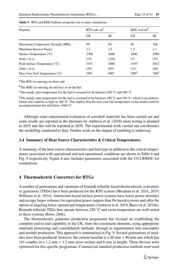
As shown in Table 5, the simulations have also tested the thermo-mechanical stresses,minimum reserve factors and aeroshell surface and predicted fuel temperatures under dif-ferent re-entry scenarios. In addition, peak external aeroshell temperatures above 3500 °Cwere obtained but for very short periods of time of order 6 seconds with the temperaturedropping to 2500 °C around 10 s after reaching the peak temperature. These simulations donot assume any tumbling and represent a worst case.
European Radioisotope Thermoelectric Generators (RTGs). . . Page 15 of 41 55
Table 5 RTG and RHU ballistic properties for re-entry simulations
Property RTG side ona RHU end onb
CR SE CR SE
Maximum Compressive Strength (MPa) 99 80 96 106
Minimum Reserve Factor 1.2 1.5 1.2 1.1
Surface Temperature (°C) 2700 2600 2800 2500
(time t in s) (13) (110) (7) (51)
Peak Surface Temperature (°C) 3531 3080 3159 2912
(time t in s) (18) (84) (11) (66)
Max Core Fuel Temperature (°C) 700c 900c 700d 700d
aThe RTG re-entering on short side
bThe RHU re-entering on end face or on the flatcThe steady state temperature for the fuel is assumed to be between 650 °C and 680 °C
dThe steady state temperature for the fuel is assumed to be between 100 °C and 150 °C, which is an underes-timate and could be as high as 300 °C. This implies that the max core fuel temperature in the model could bean underestimate but still below 1000 °C
Although some experimental evaluation of aeroshell materials has been carried out andsome results are reported in the literature by Ambrosi et al. (2018) more testing is plannedin 2019 and this will be reported in 2020. The experimental work carried out corroboratesthe modelling conducted to date. Further work on the impact of tumbling is underway.
3.4 Summary of Heat Source Characteristics & Critical Temperatures
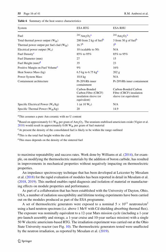
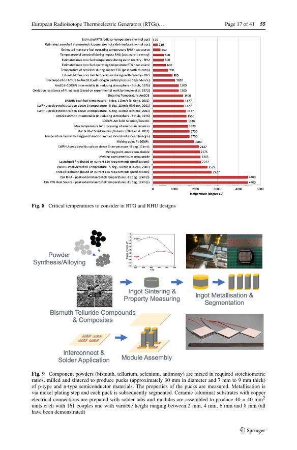
A summary of the heat source characteristics and fuel type in addition to the critical temper-atures associated with operational and non-operational conditions are shown in Table 6 andFig. 8 respectively. Figure 8 also includes parameters associated with the US LWRHU forcomparison.
4 Thermoelectric Converters for RTGs
A number of generations and variations of bismuth telluride based thermoelectric convertersor generators (TEGs) have been produced for the RTG system (Mesalam et al. 2018, 2019;Williams et al. 2014). Americium-based nuclear power systems have lower power densitiesand occupy larger volumes for equivalent power outputs than Pu-based systems and offer theoption of targeting lower operational temperatures (Ambrosi et al. 2019; Barco et al. 2019a).Bismuth telluride TEGs that operate between 220 °C and room temperature are well-suitedto these systems (Rowe 2006).
The thermoelectric generator production programme has focused on establishing thecomplete end-to-end capability in the UK, from the constituent elements, using appropriatematerials processing and consolidation methods, through to segmentation into unicouplesand module production. This approach is summarised in Fig. 9. Several generations of mod-ules have been produced; however, the current baseline is a 40 mm × 40 mm unit which has161 couples in a 1.2 mm × 1.2 mm cross section and 6 mm in height. These devices wereoptimised for this specific programme. Commercial standard production methods were used
55 Page 16 of 41 R.M. Ambrosi et al.
Table 6 Summary of the heat source characteristics
System ESA RTG ESA RHU
Fuel 241Am2O3a 241Am2O3
a
Total thermal power output (Wth) 200 from 2 kg of fuelb 3 from 30 g of fuelb
Thermal power output per fuel clad (Wth) 16.7b 3b
Electrical power output (We) 10 (scalable to 50) N/A
Fuel Densityc 85% to 95% 85% to 95%
Fuel Diameter (mm) 27 15
Fuel Height (mm)d 35 23
Positive Margin on Fuel Volumee 9% 16%
Heat Source Mass (kg) 6.5 kg to 6.75 kge 202 g
Power System Mass 10.8 kg N/A
Containment architecture Pt-20%Rh innercontainment
Pt-20%Rh inner containment
Carbon-BondedCarbon Fibre (CBCF)insulation sleeve (orequivalent)
Carbon-Bonded CarbonFibre (CBCF) insulationsleeve (or equivalent)
Specific Electrical Power (We/kg) 1 (at 10 We) N/A
Specific Thermal Power (Wth/kg) 20 14.9
aThis assumes a pure Am ceramic with no U content
bBased on approximately 0.1 Wth per gram of Am2O3. The uranium-stabilised americium oxide (Vigier et al.2018) would result in approximately 0.08 Wth per gram of fuel materialcAt present the density of the consolidated fuel is likely to be within the range outlined
dThis is the total fuel height within the cladeThis mass depends on the density of the sintered fuel
to maximise repeatability and success rates. Work done by Williams et al. (2014), for exam-ple, on modifying the thermoelectric materials by the addition of boron carbide, has resultedin improvements in mechanical properties without negatively impacting on thermoelectricproperties.
An impedance spectroscopy technique that has been developed at Leicester by Mesalamet al. (2018) for the rapid evaluation of modules has been reported in detail in Mesalam et al.(2018, 2019). This method enables rapid diagnosis and isolation of material or manufactur-ing effects on module properties and performance.
As part of a collaboration that has been established with the University of Dayton, Ohio,USA, a number of radiation susceptibility and lifetime testing experiments have been carriedout on the modules produced as part of the ESA programme.
A set of thermoelectric generators were exposed to a nominal 5 × 10¹³ neutrons/cm2
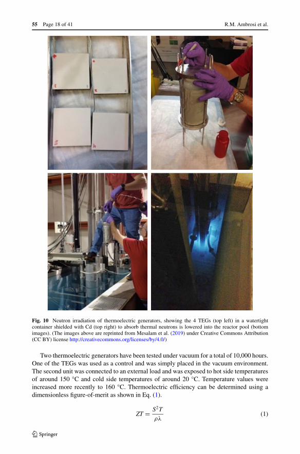
using a hard neutron spectrum (i.e. above 1 MeV with Cd shielding absorbing thermal flux).The exposure was nominally equivalent to a 12-year Mars mission cycle (including a 1-yearpre-launch assembly and storage, a 1-year cruise and 10-year surface mission) with a single50 W electric americium-based RTG. The irradiation experiment was carried out at the OhioState University reactor (see Fig. 10). The thermoelectric generators tested were unaffectedby the neutron irradiation, as reported by Mesalam et al. (2019).
European Radioisotope Thermoelectric Generators (RTGs). . . Page 17 of 41 55
Fig. 8 Critical temperatures to consider in RTG and RHU designs
Fig. 9 Component powders (bismuth, tellurium, selenium, antimony) are mixed in required stoichiometricratios, milled and sintered to produce pucks (approximately 30 mm in diameter and 7 mm to 9 mm thick)of p-type and n-type semiconductor materials. The properties of the pucks are measured. Metallisation isvia nickel plating step and each puck is subsequently segmented. Ceramic (alumina) substrates with copperelectrical connections are prepared with solder tabs and modules are assembled to produce 40 × 40 mm2
units each with 161 couples and with variable height ranging between 2 mm, 4 mm, 6 mm and 8 mm (allhave been demonstrated)
55 Page 18 of 41 R.M. Ambrosi et al.
Fig. 10 Neutron irradiation of thermoelectric generators, showing the 4 TEGs (top left) in a watertightcontainer shielded with Cd (top right) to absorb thermal neutrons is lowered into the reactor pool (bottomimages). (The images above are reprinted from Mesalam et al. (2019) under Creative Commons Attribution(CC BY) license http://creativecommons.org/licenses/by/4.0/)
Two thermoelectric generators have been tested under vacuum for a total of 10,000 hours.One of the TEGs was used as a control and was simply placed in the vacuum environment.The second unit was connected to an external load and was exposed to hot side temperaturesof around 150 °C and cold side temperatures of around 20 °C. Temperature values wereincreased more recently to 160 °C. Thermoelectric efficiency can be determined using adimensionless figure-of-merit as shown in Eq. (1).
ZT = S2T
ρλ(1)
European Radioisotope Thermoelectric Generators (RTGs). . . Page 19 of 41 55
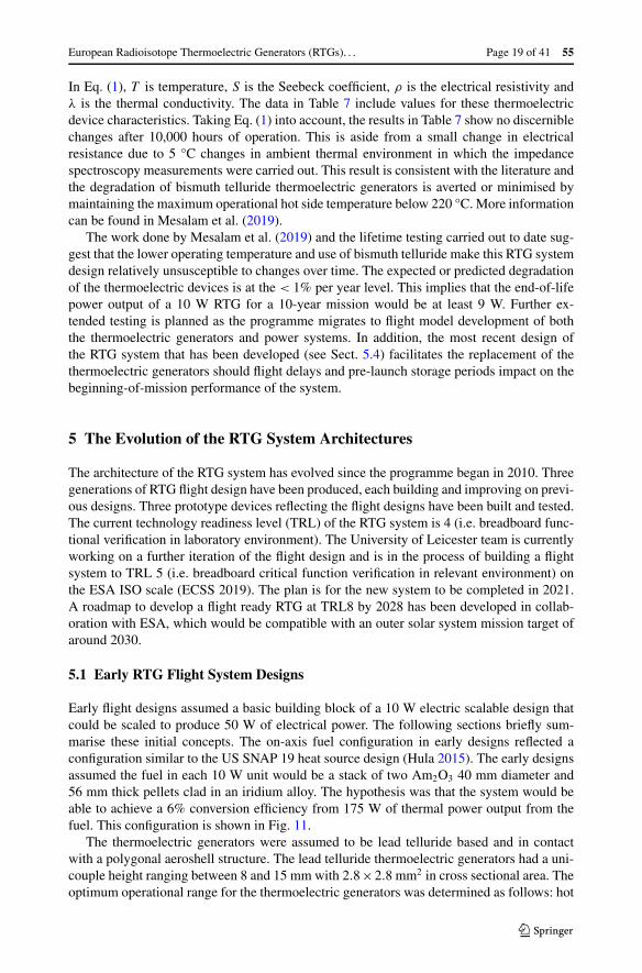
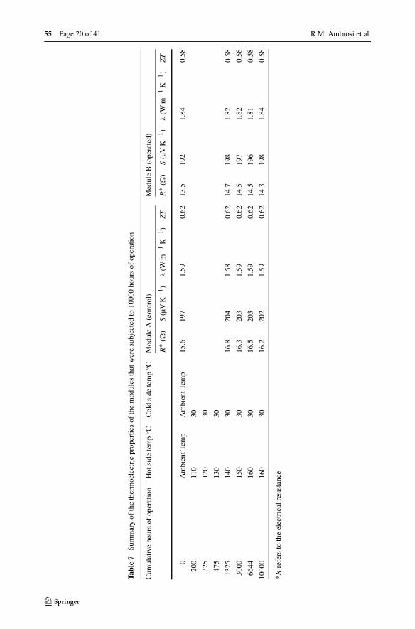
In Eq. (1), T is temperature, S is the Seebeck coefficient, ρ is the electrical resistivity andλ is the thermal conductivity. The data in Table 7 include values for these thermoelectricdevice characteristics. Taking Eq. (1) into account, the results in Table 7 show no discerniblechanges after 10,000 hours of operation. This is aside from a small change in electricalresistance due to 5 °C changes in ambient thermal environment in which the impedancespectroscopy measurements were carried out. This result is consistent with the literature andthe degradation of bismuth telluride thermoelectric generators is averted or minimised bymaintaining the maximum operational hot side temperature below 220 °C. More informationcan be found in Mesalam et al. (2019).
The work done by Mesalam et al. (2019) and the lifetime testing carried out to date sug-gest that the lower operating temperature and use of bismuth telluride make this RTG systemdesign relatively unsusceptible to changes over time. The expected or predicted degradationof the thermoelectric devices is at the < 1% per year level. This implies that the end-of-lifepower output of a 10 W RTG for a 10-year mission would be at least 9 W. Further ex-tended testing is planned as the programme migrates to flight model development of boththe thermoelectric generators and power systems. In addition, the most recent design ofthe RTG system that has been developed (see Sect. 5.4) facilitates the replacement of thethermoelectric generators should flight delays and pre-launch storage periods impact on thebeginning-of-mission performance of the system.
5 The Evolution of the RTG System Architectures
The architecture of the RTG system has evolved since the programme began in 2010. Threegenerations of RTG flight design have been produced, each building and improving on previ-ous designs. Three prototype devices reflecting the flight designs have been built and tested.The current technology readiness level (TRL) of the RTG system is 4 (i.e. breadboard func-tional verification in laboratory environment). The University of Leicester team is currentlyworking on a further iteration of the flight design and is in the process of building a flightsystem to TRL 5 (i.e. breadboard critical function verification in relevant environment) onthe ESA ISO scale (ECSS 2019). The plan is for the new system to be completed in 2021.A roadmap to develop a flight ready RTG at TRL8 by 2028 has been developed in collab-oration with ESA, which would be compatible with an outer solar system mission target ofaround 2030.
5.1 Early RTG Flight System Designs
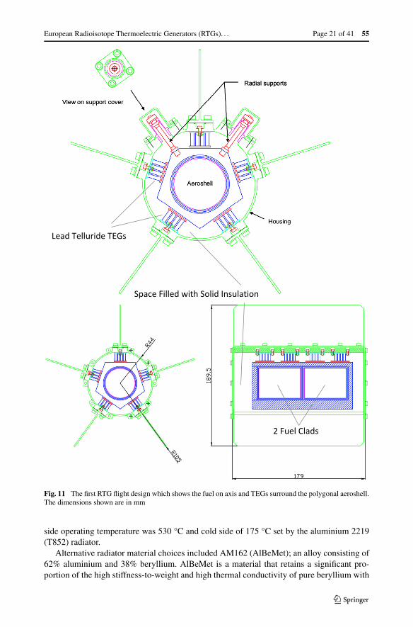
Early flight designs assumed a basic building block of a 10 W electric scalable design thatcould be scaled to produce 50 W of electrical power. The following sections briefly sum-marise these initial concepts. The on-axis fuel configuration in early designs reflected aconfiguration similar to the US SNAP 19 heat source design (Hula 2015). The early designsassumed the fuel in each 10 W unit would be a stack of two Am2O3 40 mm diameter and56 mm thick pellets clad in an iridium alloy. The hypothesis was that the system would beable to achieve a 6% conversion efficiency from 175 W of thermal power output from thefuel. This configuration is shown in Fig. 11.
The thermoelectric generators were assumed to be lead telluride based and in contactwith a polygonal aeroshell structure. The lead telluride thermoelectric generators had a uni-couple height ranging between 8 and 15 mm with 2.8×2.8 mm2 in cross sectional area. Theoptimum operational range for the thermoelectric generators was determined as follows: hot
55 Page 20 of 41 R.M. Ambrosi et al.
Tabl
e7
Sum
mar
yof
the
ther
moe
lect
ric
prop
ertie
sof
the
mod
ules
that
wer
esu
bjec
ted
to10
000
hour
sof
oper
atio
n
Cum
ulat
ive
hour
sof
oper
atio
nH
otsi
dete
mp
°CC
old
side
tem
p°C
Mod
ule
A(c
ontr
ol)
Mod
ule
B(o
pera
ted)
R∗ (
�)
S(µ
VK
−1)
λ(W
m−1
K−1
)Z
TR
∗ (�
)S
(µV
K−1
)λ
(Wm
−1K
−1)
ZT
0A
mbi
entT
emp
Am
bien
tTem
p15
.619
71.
590.
6213
.519
21.
840.
58
200
110
30
325
120
30
475
130
30
1325
140
3016
.820
41.
580.
6214
.719
81.
820.
58
3000
150
3016
.320
31.
590.
6214
.519
71.
820.
58
6644
160
3016
.520
31.
590.
6214
.519
61.
810.
58
1000
016
030
16.2
202
1.59
0.62
14.3
198
1.84
0.58
*Rre
fers
toth
eel
ectr
ical
resi
stan
ce
European Radioisotope Thermoelectric Generators (RTGs). . . Page 21 of 41 55
Fig. 11 The first RTG flight design which shows the fuel on axis and TEGs surround the polygonal aeroshell.The dimensions shown are in mm
side operating temperature was 530 °C and cold side of 175 °C set by the aluminium 2219(T852) radiator.
Alternative radiator material choices included AM162 (AlBeMet); an alloy consisting of62% aluminium and 38% beryllium. AlBeMet is a material that retains a significant pro-portion of the high stiffness-to-weight and high thermal conductivity of pure beryllium with
55 Page 22 of 41 R.M. Ambrosi et al.
an improvement in mechanical strength. Room temperature strength of AM162 AlBeMet iscomparable to 2219 aluminium alloy (375 MPa versus 372 MPa respectively), but a higherfraction of this is retained at 200 °C i.e. 76% of ultimate tensile strength and 81% of yieldstrength. For 2219 alloy both of these values reduce to 50%. At 200 °C AlBeMet offerssignificantly superior performance to 2219 aluminium alloy with a modulus to density ra-tio that is about four times higher, strength to density ratio that is about two times higherand thermal conductivity to density ratio that is about two times higher. For these reasonsAlBeMet was considered an option for weight savings, specific power considerations andimprovement in overall mechanical performance. However, the presence of beryllium madeit more challenging from a handling and procurement perspective and therefore this was notconsidered as an option at the time.
These early designs had calculated specific power values of around 2.1 W/kg for 10 Welectric units.
The transition from design to practical testing in the lab outlined that the European de-sign, based on americium fuel, would operate at lower temperatures than predicted and thatthe system level efficiency target of 6% was too high. This is discussed in detail in Sect. 5.2.One additional concern was the utilisation of lead telluride based thermoelectric generatorsoperating above the critical sublimation temperature of tellurium as described in a study byOkamoto et al. (1990) which includes the phase diagram for bismuth telluride alloys.
The implication of lower operating temperatures offered a number of benefits:
• A transition to bismuth telluride thermoelectric generators with well-established indus-trial production methods. These generators are currently the baseline. (See Sect. 4.)
• Operational temperatures below the critical sublimation temperatures of tellurium(Okamoto et al. 1990).
• Longer operational lifetimes with reduced degradation of TEGs (Mesalam et al. 2019).• Use of off-the-shelf standard materials for all components due to benign operating tem-
peratures.• Transition from iridium to platinum alloys for cladding. (See Sect. 3.2.)
Scaling the overall power output of these early design to 50 W electric units presented someadditional challenges. With the fuel on axis two options were explored.
• The first was stacking 10 W electric units to produce a 50 W electric unit. In this config-uration the modularity was at system level and the overall length of the RTG expandedfrom 179 mm to 895 mm and the specific power decreased from 2.1 W/kg to 1.3 W/kg.In this configuration the radiator fins were segmented or slotted.
• The second was to make the heat source the modular element and design an optimised50 W electric unit. This resulted in an increase in overall length from 179 mm to 669 mmand an increase in diameter from 190 to 277 mm due to the fins being part of the primarystructure. The specific power dropped from 2.1 W/kg to 1.9 W/kg.
These designs incorporated a 20% margin and the specific power reflects the inclusion ofthe margin. The design assumed lead telluride operating temperatures and did not factor inany additional requirements to increase radiator area caused by a switch to bismuth tellurideTEGs and lower cold side operating temperatures i.e. 20 °C as opposed to 175 °C.
5.2 Building the First Small-Scale RTG Laboratory Prototype
The design of the first small-scale breadboard RTG was based on the flight system architec-ture developed in the early phases of the project as shown in Sect. 5.1. The principle of a clad
European Radioisotope Thermoelectric Generators (RTGs). . . Page 23 of 41 55
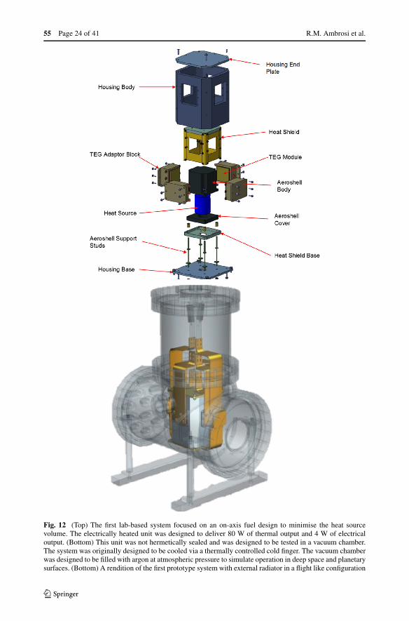
fuel element on-axis forming a compact heat source surrounded by a polygonal aeroshell toreduce the overall system volume and mass was a core element of the design philosophy. Theprototyping process retained almost all of the features of the design described in Sect. 5.1with modifications made either due to availability of specific materials or to facilitate theassembly process. Assembly integration and testing, operation in a vacuum chamber andintegration of the system with the control electronics and software were successfully com-pleted. Figure 12 shows the configuration of the breadboard and the assembled system in avacuum chamber. Key design features include:
• A multilayer gold-plated heat shield, which effectively acts as a stiff MLI-like structureand ensures that the heat flows from the heat source through the thermoelectric generatorsand minimises losses.
• The ability to test up to 4 thermoelectric generators mounted on specially designed blocksthat incorporate springs to compressively couple the thermoelectric generators to the heatsource.
• Inconel support struts designed to minimise heat losses.• The ability to operate in vacuum and with a cover gas.• Evolution in thermal management system from liquid nitrogen-based system with copper
heat pipes to a pumped fluid loop with cooling plates (Fig. 13).
The small-scale RTG breadboard was tested up to a corrected measured thermal input powerof just above 80 W, simulating the power output of an Am2O3 fuel pellet of the same volumeas the heat source module. Electrical heating was used in this design and in subsequent gen-erations of systems tested in the lab and reported in this paper. The use of electrical heatingin developing radioisotope power is a standard approach; some examples in the literatureof small scale electrically heated systems based on plutonium fuel include the systems de-veloped by Woods et al. (2006) and Balint and Emis (2006). The system initially delivereda maximum electrical power output of 3.46 ± 0.21 W, corresponding to an overall systemefficiency of 4.20 ± 0.53%. This maximum performance was achieved with two Bi2Te3
thermoelectric generator modules (consisting of 161 couples each) installed in conductivecoupling to the aeroshell in a vacuum environment. Thermal efficiencies for the RTG of73% ± 13% were calculated based on experimental results. Switching to TEGs manufac-tured using bismuth telluride (Williams et al. 2014) materials produced via spark plasmasintering produced comparable results to standard materials whilst the performance for the0.2 wt% B4C doped TEGs (Williams et al. 2014) is notably higher and meet the 5% totalsystem efficiency target, with 4 W generated for 80 W of thermal power input. This wasprimarily driven by the lower electrical resistance values of these modules and the additionof the gold-plated heat shield improving the overall thermal efficiency of the system. Theelectrical resistance at peak power for two 0.2 wt% B4C doped TEGs operating in series was35 � as opposed to 60 � for the very first generation of TEGs produced. In general, delta-Tvalues of between 160 °C and 170 °C were obtained. The most significant conclusion wasthat at least equivalent performance could be obtained from a polycrystalline thermoelectricmaterial produced by spark plasma sintering. These materials have much improved mechan-ical performance compared to conventional thermoelectric materials, giving the potential forincreased reliability and reduced risk.
5.3 Evolution in RTG Architecture: 2nd Generation Design
The switch to bismuth telluride and the lower operating temperatures of americium pre-sented the challenges of scaling power output, maintaining a modular design and keeping
55 Page 24 of 41 R.M. Ambrosi et al.
Fig. 12 (Top) The first lab-based system focused on an on-axis fuel design to minimise the heat sourcevolume. The electrically heated unit was designed to deliver 80 W of thermal output and 4 W of electricaloutput. (Bottom) This unit was not hermetically sealed and was designed to be tested in a vacuum chamber.The system was originally designed to be cooled via a thermally controlled cold finger. The vacuum chamberwas designed to be filled with argon at atmospheric pressure to simulate operation in deep space and planetarysurfaces. (Bottom) A rendition of the first prototype system with external radiator in a flight like configuration
European Radioisotope Thermoelectric Generators (RTGs). . . Page 25 of 41 55
Fig. 12 (continued)
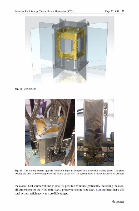
Fig. 13 The cooling system upgrade from cold finger to pumped fluid loop with cooling plates. The pipesfeeding the fluid to the cooling plates are shown on the left. The system under a shroud is shown on the right
the overall heat source volume as small as possible without significantly increasing the over-all dimensions of the RTG unit. Early prototype testing (see Sect. 5.2) outlined that a 5%total system efficiency was a credible target.
55 Page 26 of 41 R.M. Ambrosi et al.
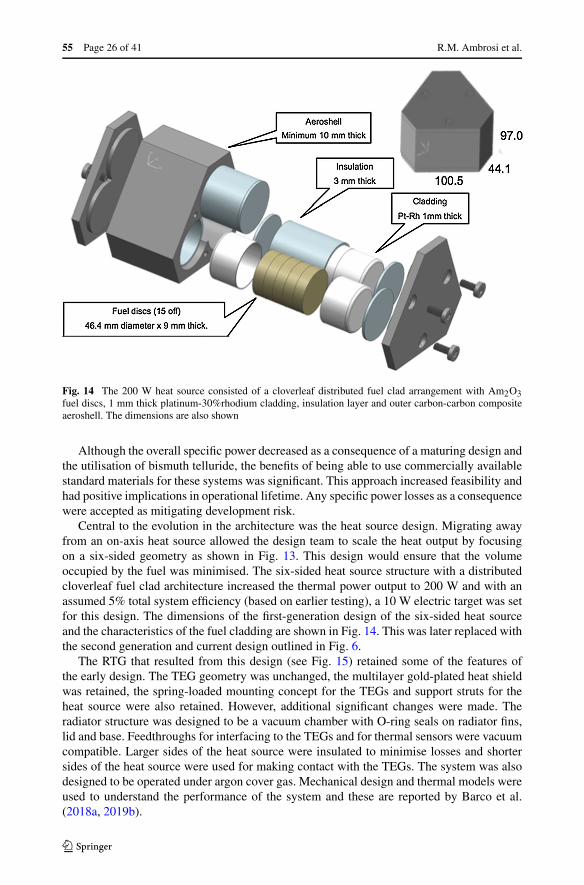
Fig. 14 The 200 W heat source consisted of a cloverleaf distributed fuel clad arrangement with Am2O3fuel discs, 1 mm thick platinum-30%rhodium cladding, insulation layer and outer carbon-carbon compositeaeroshell. The dimensions are also shown
Although the overall specific power decreased as a consequence of a maturing design andthe utilisation of bismuth telluride, the benefits of being able to use commercially availablestandard materials for these systems was significant. This approach increased feasibility andhad positive implications in operational lifetime. Any specific power losses as a consequencewere accepted as mitigating development risk.
Central to the evolution in the architecture was the heat source design. Migrating awayfrom an on-axis heat source allowed the design team to scale the heat output by focusingon a six-sided geometry as shown in Fig. 13. This design would ensure that the volumeoccupied by the fuel was minimised. The six-sided heat source structure with a distributedcloverleaf fuel clad architecture increased the thermal power output to 200 W and with anassumed 5% total system efficiency (based on earlier testing), a 10 W electric target was setfor this design. The dimensions of the first-generation design of the six-sided heat sourceand the characteristics of the fuel cladding are shown in Fig. 14. This was later replaced withthe second generation and current design outlined in Fig. 6.
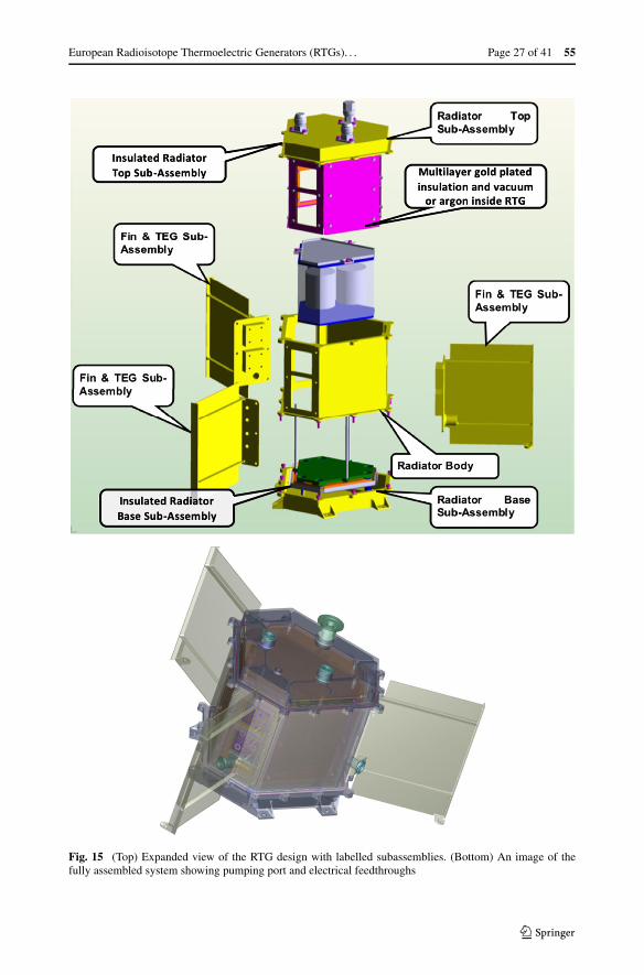
The RTG that resulted from this design (see Fig. 15) retained some of the features ofthe early design. The TEG geometry was unchanged, the multilayer gold-plated heat shieldwas retained, the spring-loaded mounting concept for the TEGs and support struts for theheat source were also retained. However, additional significant changes were made. Theradiator structure was designed to be a vacuum chamber with O-ring seals on radiator fins,lid and base. Feedthroughs for interfacing to the TEGs and for thermal sensors were vacuumcompatible. Larger sides of the heat source were insulated to minimise losses and shortersides of the heat source were used for making contact with the TEGs. The system was alsodesigned to be operated under argon cover gas. Mechanical design and thermal models wereused to understand the performance of the system and these are reported by Barco et al.(2018a, 2019b).
European Radioisotope Thermoelectric Generators (RTGs). . . Page 27 of 41 55
Fig. 15 (Top) Expanded view of the RTG design with labelled subassemblies. (Bottom) An image of thefully assembled system showing pumping port and electrical feedthroughs
55 Page 28 of 41 R.M. Ambrosi et al.
The design of the heat source is such that top, bottom and large sides of the six-sidedstructure are insulated by using a multilayer gold-plated rigid structure with very low emis-sivity that is specifically designed for this system. The combination of this design of multi-layer insulation and vacuum inside the chamber ensures that the heat flows mainly throughthe thermoelectric generators in contact with the heat source. Alternatively, Ar can be in-serted in the chamber which still provides a degree of insulation but is not as effective asvacuum. The lower operating temperature of the system also reduces the radiation lossescompared with higher power systems that operate at higher temperatures.
5.4 Building the Elegant Breadboard of the 10 W Electric RTG
The scaling of a functional lab system from initial concept to a more representative system isshown in Fig. 16. This system was fully tested. Tests included bench testing and testing in arepresentative space environment simulator at Leicester. In addition, laser Doppler vibrom-etry testing (Barco et al. 2018a, 2018b, 2019b), using specialised facilities at the Universityof Leicester, enabled the team to verify the mechanical models produced for the systemwithout resorting to destructive conventional vibration tests. This RTG system incorporatedsix thermoelectric modules supported by the fins of the radiator. Tests with argon cover gaswere also executed. Notable features of this system include (see Fig. 16):
• Carbon-carbon composite aeroshell for the heat source.• Multilayer gold-plated heat shield.• System is a sealed vacuum chamber with pumping port and electrical feedthroughs for
heating, thermal sensing and TEG outputs.• System can be operated under cover gas.• System mass of 9.4 kg excluding the liquid-cooling plates.• Pumped fluid loop cooling system with cooling plates attached to the radiator.
5.5 Refinement of the RTG Architecture: 3rd Generation Design
The architecture was further refined to reflect the updated heat source design that is shownin Sect. 3.1. The design (as shown in Fig. 17) was updated to reflect the following:
• The work by Watkinson et al. (2017b) suggests that a smaller diameter fuel form com-pared to early designs is preferred in order to ensure the successful consolidation of ameri-cium ceramic fuel. This is reflected in the clad design shown in Sects. 2.2 and 3.2.
• Standardisation of fuel clad manufacturing processes across RHU and RTG systems.• The work by Vigier et al. (2018) also suggests that the fuel form is likely to be a mixed
oxide of americium and uranium-based fuels where the latter could comprise 15% of thetotal fuel mass.
• The need to potentially accommodate more fuel mass while constraining the heat sourcevolume.
• A larger radiator to ensure that TEG cold side temperatures are in line with the ZT curveof bismuth telluride.
Thermal analyses of this design (Table 8, Fig. 18) show temperatures in line with the re-quirements of the baseline thermoelectric generator design described in Sect. 4.
The heat source itself has been modelled in detail, some of which is shown in Fig. 18. Thetop panel of Fig. 18 provides an indication of the heat source temperatures at the interfaceswith the TEGs. The TEG interface temperatures in this model are at around 190 °C and
European Radioisotope Thermoelectric Generators (RTGs). . . Page 29 of 41 55
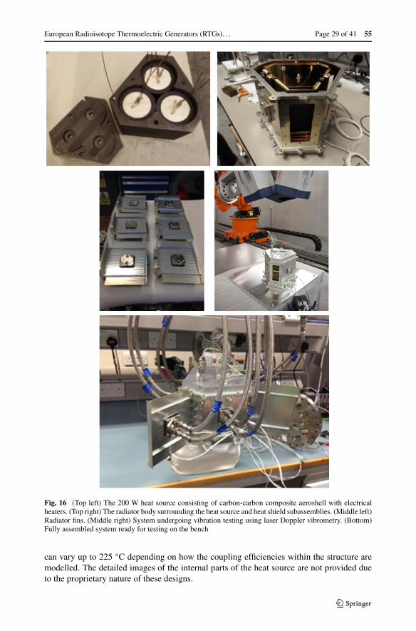
Fig. 16 (Top left) The 200 W heat source consisting of carbon-carbon composite aeroshell with electricalheaters. (Top right) The radiator body surrounding the heat source and heat shield subassemblies. (Middle left)Radiator fins. (Middle right) System undergoing vibration testing using laser Doppler vibrometry. (Bottom)Fully assembled system ready for testing on the bench
can vary up to 225 °C depending on how the coupling efficiencies within the structure aremodelled. The detailed images of the internal parts of the heat source are not provided dueto the proprietary nature of these designs.
55 Page 30 of 41 R.M. Ambrosi et al.
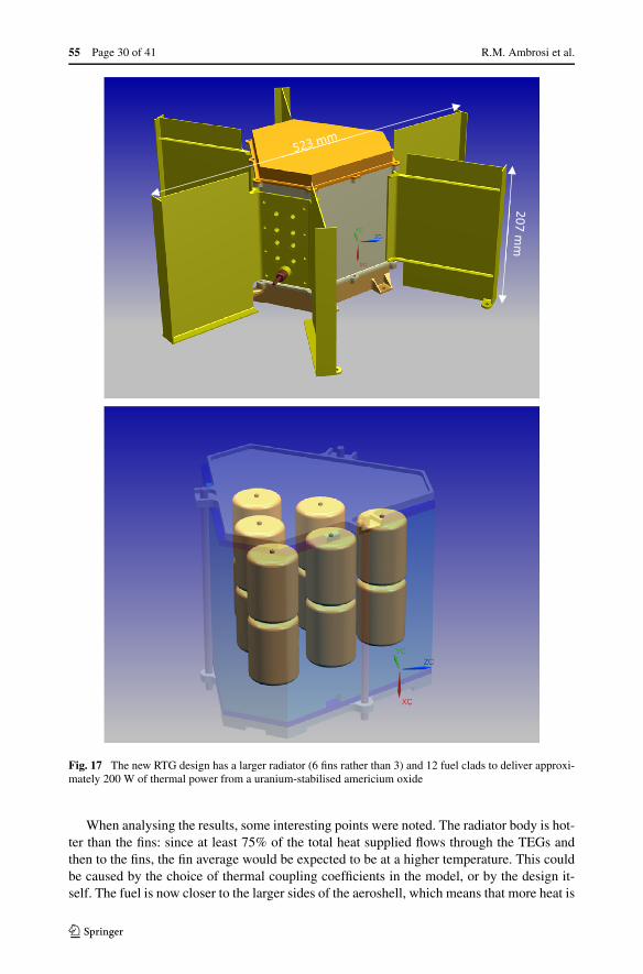
Fig. 17 The new RTG design has a larger radiator (6 fins rather than 3) and 12 fuel clads to deliver approxi-mately 200 W of thermal power from a uranium-stabilised americium oxide
When analysing the results, some interesting points were noted. The radiator body is hot-ter than the fins: since at least 75% of the total heat supplied flows through the TEGs andthen to the fins, the fin average would be expected to be at a higher temperature. This couldbe caused by the choice of thermal coupling coefficients in the model, or by the design it-self. The fuel is now closer to the larger sides of the aeroshell, which means that more heat is
European Radioisotope Thermoelectric Generators (RTGs). . . Page 31 of 41 55
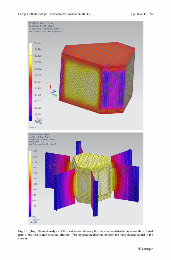
Fig. 18 (Top) Thermal analysis of the heat source showing the temperature distribution across the externalparts of the heat source structure. (Bottom) The temperature distribution from the finite element model of thesystem

55 Page 32 of 41 R.M. Ambrosi et al.
Table 8 Results from the finiteelement thermal analysis for thenew designaThe hot side of thethermoelectric generators canvary depending on the couplingefficiencies in the model. In thelatest design this is 224 °C butcan range between 190 °C and225 °CbSimilarly the TEG cold side canalso vary between 10 °C and25 °C in the thermal model
Components Temperature[°C]
Aeroshell 226
TEG hot face 224a
TEG cold face 25b
Radiator body (average) 23
Fin (average) 16
Fin (tips) 0
Radiator & fin (average) 21
likely to be transferred to the radiator body directly and not via the TEG modules. This couldalso suggest that the fin conductivity is too low in the model and that losses are higher thanexpected. This analysis outlines a likely worst-case scenario that will need to be confirmedby measurement. Particularly given the higher thermal efficiencies obtained experimentallywith earlier designs suggest that 80% to 90% of the heat flows through the TEGs. Measure-ments based on the latest design are planned in future phases of the programme once thebuild of this new model has been completed.
6 Designing and Building the RHU
Three generations of RHU flight design have been produced, each building and improvingon previous designs. Two prototype devices reflecting the flight designs have been built andtested. In addition, mechanical models have been developed for vibration testing and somesafety studies. The current TRL of the RHU system is 4 (i.e. breadboard functional verifi-cation in a laboratory environment). The University of Leicester team is currently workingon a further iteration of the flight design and is in the process of building a flight systemto TRL 5 (i.e. breadboard critical functional verification in a relevant environment) on thenew ESA ISO scale (ECSS 2017). The plan is for the new RHU system to be completedin 2020. A roadmap to develop a flight-ready RHU by 2025 or 2026 has been developedin collaboration with ESA, which would be compatible with an outer solar system missiontarget of around 2030.
The RHU design architecture is highlighted in Sect. 2 and details of the mechanical andthermal performance are provided in detail by Barco et al. (2018b). Models developed byBarco et al. (2018b, 2019a) for both the thermal and the structural analysis of the RHUassume good contact between the different layers of the heat source under operating condi-tions. Rapid heating during assembly would result in a compression of all the layers due tothermal expansion. It is not pre-defined how an ESA RHU would be thermally integrated ina spacecraft; therefore, three cases were analysed in order to cover all the possible configu-rations of the RHU installation on a spacecraft:
• Radiation to the internal spacecraft environment and conduction via a thermal manage-ment interface.
• Conduction only via a thermal management interface with the spacecraft, which has atemperature of 20 °C. This would require insulation around the RHU to minimise radia-tion.
• Radiation only to the internal spacecraft environment (20 °C).
European Radioisotope Thermoelectric Generators (RTGs). . . Page 33 of 41 55
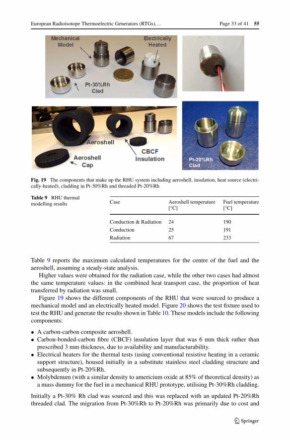
Fig. 19 The components that make up the RHU system including aeroshell, insulation, heat source (electri-cally-heated), cladding in Pt-30%Rh and threaded Pt-20%Rh
Table 9 RHU thermalmodelling results Case Aeroshell temperature
[°C]Fuel temperature[°C]
Conduction & Radiation 24 190
Conduction 25 191
Radiation 67 233
Table 9 reports the maximum calculated temperatures for the centre of the fuel and theaeroshell, assuming a steady-state analysis.
Higher values were obtained for the radiation case, while the other two cases had almostthe same temperature values: in the combined heat transport case, the proportion of heattransferred by radiation was small.
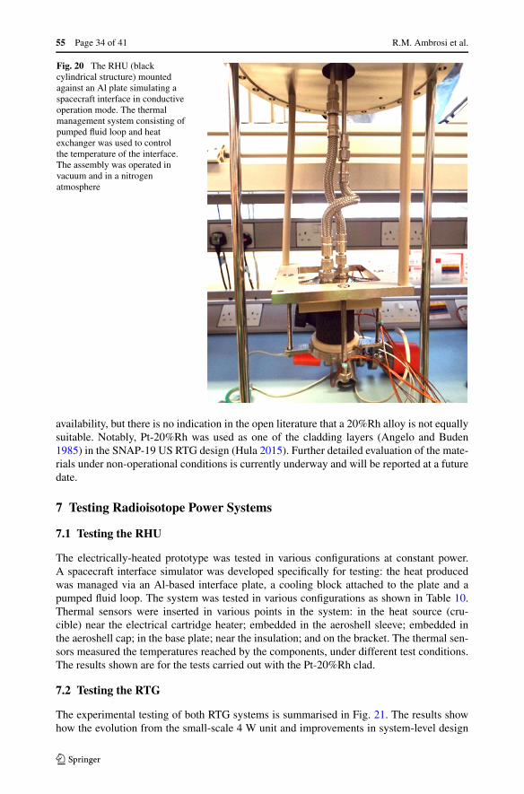
Figure 19 shows the different components of the RHU that were sourced to produce amechanical model and an electrically heated model. Figure 20 shows the test fixture used totest the RHU and generate the results shown in Table 10. These models include the followingcomponents:
• A carbon-carbon composite aeroshell.• Carbon-bonded-carbon fibre (CBCF) insulation layer that was 6 mm thick rather than
prescribed 3 mm thickness, due to availability and manufacturability.• Electrical heaters for the thermal tests (using conventional resistive heating in a ceramic
support structure), housed initially in a substitute stainless steel cladding structure andsubsequently in Pt-20%Rh.
• Molybdenum (with a similar density to americium oxide at 85% of theoretical density) asa mass dummy for the fuel in a mechanical RHU prototype, utilising Pt-30%Rh cladding.
Initially a Pt-30% Rh clad was sourced and this was replaced with an updated Pt-20%Rhthreaded clad. The migration from Pt-30%Rh to Pt-20%Rh was primarily due to cost and
55 Page 34 of 41 R.M. Ambrosi et al.
Fig. 20 The RHU (blackcylindrical structure) mountedagainst an Al plate simulating aspacecraft interface in conductiveoperation mode. The thermalmanagement system consisting ofpumped fluid loop and heatexchanger was used to controlthe temperature of the interface.The assembly was operated invacuum and in a nitrogenatmosphere
availability, but there is no indication in the open literature that a 20%Rh alloy is not equallysuitable. Notably, Pt-20%Rh was used as one of the cladding layers (Angelo and Buden1985) in the SNAP-19 US RTG design (Hula 2015). Further detailed evaluation of the mate-rials under non-operational conditions is currently underway and will be reported at a futuredate.
7 Testing Radioisotope Power Systems
7.1 Testing the RHU
The electrically-heated prototype was tested in various configurations at constant power.A spacecraft interface simulator was developed specifically for testing: the heat producedwas managed via an Al-based interface plate, a cooling block attached to the plate and apumped fluid loop. The system was tested in various configurations as shown in Table 10.Thermal sensors were inserted in various points in the system: in the heat source (cru-cible) near the electrical cartridge heater; embedded in the aeroshell sleeve; embedded inthe aeroshell cap; in the base plate; near the insulation; and on the bracket. The thermal sen-sors measured the temperatures reached by the components, under different test conditions.The results shown are for the tests carried out with the Pt-20%Rh clad.
7.2 Testing the RTG
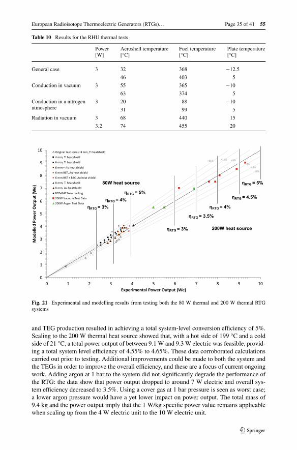
The experimental testing of both RTG systems is summarised in Fig. 21. The results showhow the evolution from the small-scale 4 W unit and improvements in system-level design
European Radioisotope Thermoelectric Generators (RTGs). . . Page 35 of 41 55
Table 10 Results for the RHU thermal tests
Power[W]
Aeroshell temperature[°C]
Fuel temperature[°C]
Plate temperature[°C]
General case 3 32 368 −12.5
46 403 5
Conduction in vacuum 3 55 365 −10
63 374 5
Conduction in a nitrogenatmosphere
3 20 88 −10
31 99 5
Radiation in vacuum 3 68 440 15
3.2 74 455 20
Fig. 21 Experimental and modelling results from testing both the 80 W thermal and 200 W thermal RTGsystems
and TEG production resulted in achieving a total system-level conversion efficiency of 5%.Scaling to the 200 W thermal heat source showed that, with a hot side of 199 °C and a coldside of 21 °C, a total power output of between 9.1 W and 9.3 W electric was feasible, provid-ing a total system level efficiency of 4.55% to 4.65%. These data corroborated calculationscarried out prior to testing. Additional improvements could be made to both the system andthe TEGs in order to improve the overall efficiency, and these are a focus of current ongoingwork. Adding argon at 1 bar to the system did not significantly degrade the performance ofthe RTG: the data show that power output dropped to around 7 W electric and overall sys-tem efficiency decreased to 3.5%. Using a cover gas at 1 bar pressure is seen as worst case;a lower argon pressure would have a yet lower impact on power output. The total mass of9.4 kg and the power output imply that the 1 W/kg specific power value remains applicablewhen scaling up from the 4 W electric unit to the 10 W electric unit.
55 Page 36 of 41 R.M. Ambrosi et al.
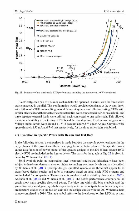
Fig. 22 Summary of the small-scale RTG performance including the more recent 10 W electric unit
Electrically, each pair of TEGs on each radiator fin operated in series, with the three seriespairs connected in parallel. This configuration would provide redundancy at the system level,with failure of a TEG not resulting in total failure at system level. During testing, TEGs withsimilar electrical and thermoelectric characteristics were connected in series on each fin, andthree separate external loads were utilised, each connected to one series pair. This allowedmaximum flexibility in the testing of TEGs and the investigation of optimum configurations.Voltage output levels were around 11 V in vacuum and 9.5 V under Ar gas. Currents wereapproximately 850 mA and 740 mA respectively, for the three series pairs combined.
7.3 Evolution in Specific Power with Design and Test Data
In the following section, a comparison is made between the specific power estimates in theearly phases of the project and those emerging from the latter phases. The specific powervalues as a function of power output of the updated designs of the 200 W heat source 10 Welectric RTG are included in the figures below. The basis for the graph in Fig. 22 is given indetail by Williams et al. (2011).
Solid symbols (with no connecting lines) represent studies that historically have beensubject to hardware demonstration or higher technology readiness levels and are describedby Williams et al. (2011). Concept designs (unfilled symbols) are those that appear to bepaper-based design studies and refer to concepts based on small-scale RTG systems andare included for comparison. These concepts are described in detail by Pustovalov (2007),Abelson et al. (2004) and Williams et al. (2011). The dotted performance contours on thegraph show mass-specific electrical power. The blue line with solid blue symbols and thegreen line with solid green symbols respectively refer to the outputs from the early systemarchitecture studies with the fuel on-axis and the design studies with the 200 W thermal heatsource completed in 2014. The red symbol refers to the breadboard or first RTG lab system
European Radioisotope Thermoelectric Generators (RTGs). . . Page 37 of 41 55
delivering 4 W of electrical power. The orange line with solid orange symbols refers to themost recent updated RTG system based on the 200 W design with 12 clads rather than 3clads, which was completed in 2018. The plot shows that exceeding the 2 W/kg specificpower level is challenging with an Am-based power system.
8 Conclusion
The ESA radioisotope power systems programme has resulted in the evolution of RTG sys-tem design from a 4 W electric system to a 10 W electric system. Standard heat sourcedesigns for RTG and RHU application have been produced to form the building blocks ofEuropean RTGs and RHUs that would be deployed in space. In the case of the RTG sys-tems developed, mass-specific power levels of 1 W/kg have been demonstrated. Mechanicaland thermal models produced correlate effectively with experimental tests. Thermoelectricproduction methods have been established in the UK with the capability to produce be-spoke thermoelectric modules based on bismuth telluride technology. Testing on the benchand in a space environment simulator was carried out. Two 10 W electric lab prototypeswere successfully tested, incorporating carbon-carbon composite and graphite aeroshells re-spectively. Additional testing of subcomponents (cladding, aeroshell materials) under non-operational conditions was successfully completed and reported by Ambrosi et al. (2019).Extended operation testing of TEGs was successfully completed (Mesalam et al. 2019). Irra-diation of TEGs was also successfully completed (Mesalam et al. 2019). Extended lifetimeand radiation testing suggest that bismuth telluride TEG technology is robust partly due tolower operating temperatures of these RTG systems.
A scaled 50 W electric unit is currently being designed, based on optimisation of the10 W electric unit as the system level building block. The focus is less on specific power butrather optimisation of the power output, reliability and longevity of the building block (i.e.the 10 W electric unit). This approach will reduce the development time and control the costfor larger RTGs applicable to missions requiring several hundred Watts of electrical power.This approach will also make building and assembly of RTG systems with radioisotope fuelmore straightforward.
The RHU for the ESA RPS programme has been designed and tested in a representativeconfiguration and environment. The RHU is a 3 W thermal unit with an overall mass of200 g, giving a specific thermal power of 15 W/g. This is a competitive design and can beoperated in a number of modes: conduction only, radiation only, or both conduction andradiation.
Materials for the RTG and RHU laboratory test units reflect the flight designs and includecarbon-carbon composites for the aeroshell and platinum alloy fuel cladding. A frit vent hasbeen also added in the design of the cladding for both RTG and RHU systems, to allowthe helium and the oxygen released by the fuel to flow out of the inner containment and,therefore, avoid stresses on the clad. This frit development is currently underway and willfeature in future prototype models.
Concerning the fuel development, pellet sintering was performed both on surrogate ma-terials and on americium oxide. The stabilisation of cubic americium oxide with uraniumwas proposed to improve the ceramic properties.
The next steps in the programme (already underway) include:
• To improve the characterisation of the Pt-20%Rh thermal and mechanical properties, es-pecially at high temperatures.
• Although successful clad welding trials were recently completed, data and welds are stillbeing analysed and further work on clad welding is required.
55 Page 38 of 41 R.M. Ambrosi et al.
• To perform new launch failure and Earth re-entry performance studies.• To perform new analyses for the frit vent design (choice of porosity and frit particle sizes),
also keeping in mind the need for manufacturing and testing.• To perform further vibration tests (to find natural frequencies, and through a wider vibra-
tion spectrum).• To further develop the americium fuel ceramic production, achieving better control of the
microstructure and the open porosity, investigating 16O enrichment to decrease neutronproduction, determining the minimum amount of uranium needed to stabilise the cubicoxide form in freshly purified 241Am and scaling up the ceramic production.
• To perform interaction tests between americium fuel ceramic and the cladding material.
The RTG systems outlined in this paper could be easily adapted to provide power in chal-lenging environments on Earth such as deep geological repositories for storing nuclearwaste, deep sea applications or in locations where a deployable long-lived power systemis required. The systems outlined in this paper and variations of these could be modified andadapted to deploy in terrestrial environments. RHUs could be used to make very small RTGsystems delivering power outputs between 100 mW and 1 W electric.
The ESA radioisotope power systems programme has been active since 2009, when thefirst radioisotope selection studies were initiated. Since then, a series of projects have ad-vanced the development of heat sources and heat-to-electricity conversion technologies thatcould enable a range of ESA missions in the latter half of the 2020s and into the 2030s.The University of Leicester team has been working on three aspects of the programme since2010: radioisotope thermoelectric generators (RTGs); radioisotope heater units (RHUs); andsupporting the National Nuclear Laboratory in developing the americium fuel form. Thetechnology programme to date has advanced these technologies to TRL 4 or “componentand/or breadboard functional verification in laboratory environment”. By the early 2020s,the maturity levels of these systems (i.e. RTGs and RHUs) will reach TRL6 on the ISO scaleor “model demonstrating the critical functions of the element in a relevant environment”,preparing the way for the utilisation of these systems in future missions. In the course ofthe TRL progression to date, the various system aspects and the radioisotope fuel work haveconverged into a programme where the different elements that make up space nuclear powersystems can no longer be developed in parallel or isolation, given that each subcomponenthas an impact on the overall system design and performance. This has resulted in the es-tablishment of a unique community of partners across academia and industry as well as theidentification of the facilities and infrastructure that have enabled ESA to establish a sus-tainable space nuclear power technology programme. Europe has all of the expertise andfacilities to offer competitive radioisotope power solutions for both planetary science anddeep space missions. In addition, the ESA programme has developed significant credibilityon the international stage. This is embodied by the establishment of a network of interna-tional partners which has the potential to open up bilateral or multilateral exploration orscientific initiatives in the future.
Acknowledgements This work is funded by the European Space Agency. The authors would like to thankthe UK Space Agency and in particular Sue Horne, Nick Cox, Elizabeth Seaman, Tony Mears, Helen Roberts,Libby Jackson. The results outlined in this programme would not have been possible without the support ofMatthew Stuttard. The authors would also like to thank the team at the University of Dayton: ChadwickBarklay, Steven Goodrich, Christopher Whiting and Ronald Hoffman for their continued help and support.The authors like to thank Jan König and Martin Jägle from Fraunhofer IPM in Freiburg for their early workand collaboration on lead telluride thermoelectric generators. Robert C O’Brien whose PhD work sponsoredby the Engineering and Physical Science Research Council contributed to the very early research at Leicesterin this field.
European Radioisotope Thermoelectric Generators (RTGs). . . Page 39 of 41 55
Publisher’s Note Springer Nature remains neutral with regard to jurisdictional claims in published mapsand institutional affiliations.
Open Access This article is licensed under a Creative Commons Attribution 4.0 International License,which permits use, sharing, adaptation, distribution and reproduction in any medium or format, as long asyou give appropriate credit to the original author(s) and the source, provide a link to the Creative Commonslicence, and indicate if changes were made.The images or other third party material in this article are in-cluded in the article’s Creative Commons licence, unless indicated otherwise in a credit line to the material.If material is not included in the article’s Creative Commons licence and your intended use is not permittedby statutory regulation or exceeds the permitted use, you will need to obtain permission directly from thecopyright holder.To view a copy of this licence, visit http://creativecommons.org/licenses/by/4.0/.
References
R.D. Abelson et al., NASA Jet Propulsion Laboratory, JPL Pub 04–10 (2004). https://trs.jpl.nasa.gov/handle/2014/40856, accessed 30 August 2019
H.J. Allen, A.J. Eggers, in National Advisory Committee for Aeronautics Report, vol. 1381 (1957), p. 1125R.M. Ambrosi, A. Barco, H. Williams et al., in Proceedings Nuclear and Emerging Technologies for Space
Conference (American Nuclear Society, LaGrange Park, 2018), 978-0-89448-744-6R.M. Ambrosi, E.J. Watkinson, A. Barco, R. Mesalam et al., in Proceedings IEEE Aerospace Conference
(2019). https://doi.org/10.1109/AERO.2019.8742245J.A. Angelo, D. Buden, Space Nuclear Power. Orbit, a Foundation Series (1985), p. 138C.S. Arridge, N. Achilleos, J. Agarwal et al., Planet. Space Sci. 104, 122–140 (2014). https://doi.org/10.1016/
j.pss.2014.08.009T.S. Balint, N.D. Emis, AIP Conf. Proc. 813, 327 (2006). https://doi.org/10.1063/1.2169209A. Barco, R.M. Ambrosi, H.R. Williams et al. (American Nuclear Society), in Proceedings of Nuclear and
Emerging Technologies for Space (NETS 2018), Paper 24177 (2018a). 978-0-89448-744-6A. Barco, R.M. Ambrosi, H.R. Williams et al. (American Nuclear Society), in Proceedings of Nuclear and
Emerging Technologies for Space (NETS 2018), Paper 24176 (2018b). 978-0-89448-744-6A. Barco, C. Fongarland, R.M. Ambrosi et al., in Proceedings IEEE Aerospace Conference (2019a). https://
doi.org/10.1109/AERO.2019.8741744A. Barco, R.M. Ambrosi, H.R. Williams et al., in Proceedings IEEE Aerospace Conference (2019b). https://
doi.org/10.1109/AERO.2019.8741786G.L. Bennett, AIAA Pap. 2006(4191), 26–29 (2012). https://doi.org/10.2514/6.2006-4191J. Birden, K. Jordan, US Patent 2,913,510 (1959). https://patentimages.storage.googleapis.com/1a/64/d3/
0acea71016065f/US2913510.pdf, accessed 30 August 2019A.M. Brandis, C.O. Johnston, in 45th AIAA Plasmadynamics and Lasers Conference Atlanta, GA (2014).
https://doi.org/10.2514/6.2014-2374T. Caillat et al., in Presented at Direct Thermal-to-Electrical Energy Conversion Conference, San
Diego (2006). https://trs.jpl.nasa.gov/bitstream/handle/2014/40238/06-2720.pdf?sequence=1, accessed30 August 2019
T.D. Chikalla, L. Eyring, J. Inorg. Nucl. Chem. 30, 133 (1968)R.W. Detra, H. Hidalgo, J. Am. Rocket Soc. 31, 318–321 (1961). https://doi.org/10.2514/8.5471M.S. El Genk, J-M. Tournier, Nucl. Eng. Des. 208, 29–50 (2001). https://doi.org/10.1016/
S0029-5493(01)00351-XE. Epifano, C. Guéneau, R.C. Belin, R. Vauchy et al., Inorg. Chem. 56(13), 7416–7432 (2017). https://doi.org/
10.1021/acs.inorgchem.7b00572European Cooperation for Space Standardisation—ECSS, ECSS-E-HB-11A (2017). https://ecss.nl/home/
ecss-e-hb-11a-technology-readiness-level-trl-guidelines-1-march-2017/, accessed 30 August 2019European Space Agency (ESA), Safety Policy on the Use of Nuclear Power Sources, United Nations Office
for Outer Space Affairs, Committee on the Peaceful Uses of Outer Space, Scientific and TechnicalSubcommittee, Fifty-sixth session. Paper A/AC.105/C.1/2019/CRP.10 (2019)
J.A. Fay, F.R. Riddell, J. Aeronaut. Sci. 25(2), 54 (1958)G. Gilley, M. Crook, T. Bradshaw et al., in International Cryocooler Conference Proceedings (2018).
https://cryocooler.org/resources/Documents/C20/387.pdf, accessed 11 November 2019S.F. Hoerner, Fluid Dynamic Drag: Practical Information on Aerodynamic Drag and Hydrodynamic Resis-
tance, Brick Town, New Jersey (1965)T.C. Holgate et al., J. Electron. Mater. (2014). https://doi.org/10.1007/s11664-014-3564-9
55 Page 40 of 41 R.M. Ambrosi et al.
G. Hula (ed.), Idaho National Laboratory, US Department of Energy, Atomic Power in Space II: A History(2015). https://www.inl.gov/research-program/space-power-systems/, accessed 30 August 2019
H. Inouye et al., Oak Ridge National Lab Report, ORNL-4813, UC-33 Propulsion and Energy Conversion(1972). https://www.osti.gov/servlets/purl/4633320, accessed 30 August 2019
R.I. Jaffee et al., Refractory Metals and Alloys, vol. 11 (1961), pp. 383–464E.W. Johnson, Monsanto Research Corporation, Mound Laboratory Report, MLM-3250(OP) (1984).
https://www.osti.gov/servlets/purl/5688898, accessed 30 August 2019R.D. Klett, Sandia Laboratory Report, SC-RR-64-2141 (1964). https://www.osti.gov/servlets/purl/4630398,
accessed 30 August 2019R.J.M. Konings, O. Beneš, A. Kovács et al., J. Phys. Chem. Ref. Data 43(1), 013101 (2014). https://doi.org/
10.1063/1.4825256D.P. Kramer, R.M. Ambrosi, E.J. Watkinson et al. (American Nuclear Society), in Proceedings of Nuclear
and Emerging Technologies for Space (NETS 2018), Paper 24209 (2018). 978-0-89448-744-6M. Lacoste, A. Lacombe, P. Joyez et al., Acta Astronaut. 50(6), 357 (2002). https://doi.org/10.1016/
S0094-5765(01)00178-3F. Lebreton, R.C. Belin, T. Delahye et al., J. Solid State Chem. 196, 217 (2012). https://doi.org/10.1016/
j.jssc.2012.06.027A. Masters, N. Achilleos, C.B. Agnor et al., Planet. Space Sci. 104, 108–121 (2014)P. McLure, in A Presentation to: The National Academies of Sciences, Engineering, and Medicine
Committee on Biological and Physical Sciences in Space, Los Alamos National Lab (2018).http://sites.nationalacademies.org/cs/groups/ssbsite/documents/webpage/ssb_185452.pdf, accessed 30August 2019
Mersen, https://www.mersen.com/products/graphite-specialties/carboncarbon-composite/carbon-carbon-composite-grades, accessed 30 August 2019
R. Mesalam, H.R. Williams, R.M. Ambrosi et al., Appl. Energy 226, 1208–1218 (2018). https://doi.org/10.1016/j.apenergy.2018.05.041
R. Mesalam, H.R. Williams, R.M. Ambrosi et al., AIP Adv. 9(5), 055006 (2019). https://doi.org/10.1063/1.5095619
T. Nishi, A. Itoh, K. Ichise, Y. Arai, J. Nucl. Mater. 414(2), 109–113 (2011). https://doi.org/10.1016/j.jnucmat.2011.01.019
H. Okamoto, et al., Bi-Te (Bismuth-Tellurium), Binary Alloy Phase Diagrams, ed. by T.B. Massalski, 2ndedn. (1990), pp. 800–801
A.A. Pustovalov, in Proceedings of the 5th European conference on thermoelectrics, Odessa, Ukraine, 10–12September (2007). http://ect2007.its.org/ect2007.its.org/system/files/u1/pdf/05.pdf, accessed 5 Decem-ber 2019
Z.R. Putnam, R.D. Braun, J. Guid. Control Dyn. 38(3), 414 (2015)D.M. Rowe, Thermoelectrics Handbook: Macro to Nano (CRC Taylor and Francis, Boca Raton, 2006), pp. 7–
10C. Sari, E. Zamorani, J. Nucl. Mater. 37(3), 324–330 (1970). https://doi.org/10.1016/0022-3115(70)90162-5M. Sarsfield, C. Campbell, C. Carrigan et al., E3S Web Conf. 16, 05003 (2017). https://doi.org/10.1051/
e3sconf/20171605003M. Sarsfield, J. Brown, C. Campbell et al., Prog. Nucl. Energy 106, 396–416 (2018). https://doi.org/
10.1016/j.pnucene.2018.02.008W.W. Schulz, The Chemistry of Americium. ERDA Critical Review Series (1976). https://www.osti.gov/
servlets/purl/7232133, accessed 30 August 2019R.E. Tate LANL Report, LA-9078-MS (1982). https://www.osti.gov/servlets/purl/5253319, accessed 30 Au-
gust 2019C. Thiriet, R.J.M. Konings, J. Nucl. Mater. 320(3), 292–298 (2003). https://doi.org/10.1016/
S0022-3115(03)00188-0D.J. Trump, Presidential Memorandum on Launch of Spacecraft Containing Space Nuclear Systems
(2019). https://www.whitehouse.gov/presidential-actions/presidential-memorandum-launch-spacecraft-containing-space-nuclear-systems/, accessed 30 August 2019
J-F. Vigier, D. Freis, P. Pöml et al., Inorg. Chem. 578, 4317–4327 (2018). https://doi.org/10.1021/acs.inorgchem.7b03148
E.J. Watkinson, Ph.D. Thesis “Space Nuclear Power Systems: Enabling Innovative Space Science and Ex-ploration Missions” (2017). http://hdl.handle.net/2381/40461
E.J. Watkinson, C.E. Whiting, C.D. Barklay et al. (American Nuclear Society), in Proceedings of Nuclearand Emerging Technologies for Space Conference, Paper 5041 (2015)
E.J. Watkinson, R.M. Ambrosi, H.R. Williams et al., J. Nucl. Mater. 486, 308–322 (2017a). https://doi.org/10.1016/j.jnucmat.2017.01.011

European Radioisotope Thermoelectric Generators (RTGs). . . Page 41 of 41 55
E.J. Watkinson, R.M. Ambrosi, D.P. Kramer et al., J. Nucl. Mater. 491, 18–30 (2017b). https://doi.org/10.1016/j.jnucmat.2017.04.028
E.J. Watkinson, D. Chateigner, R.M. Ambrosi et al., J. Nucl. Mater. 507, 158–163 (2018). https://doi.org/10.1016/j.jnucmat.2018.05.003
E.J. Watkinson, R. Ambrosi, D. Freis et al., in Proceedings IEEE Aerospace Conference (2019). https://doi.org/10.1109/AERO.2019.8741815
H.R. Williams, R.M. Ambrosi, N.P. Bannister et al., Int. J. Energy Res. (2011). https://doi.org/10.1002/er.1864
H.R. Williams, H. Ning, M.J. Reece, R.M. Ambrosi et al., J. Nucl. Mater. 433(1–3), 116–123 (2013).https://doi.org/10.1016/j.jnucmat.2012.09.030
H.R. Williams, R.M. Ambrosi, K. Chen et al., J. Alloys Compd. 626, 368–374 (2014)B.G. Woods, L.C. Arnold, T.S. Balint, AIP Conf. Proc. 813, 348 (2006). https://doi.org/10.1063/1.2169212Y. Yamada et al., Metrologia 38, 213–219 (2001). https://doi.org/10.1088/0026-1394/38/3/3