Embed Size (px)
Citation preview

EUROPEAN LI-ION BATTERY ADVANCED
MANUFACTURING FOR ELECTRIC VEHICLES
Quality control Battery electrode manufacturing steps optical surface inspection …
a

1
Quality control
Battery electrode manufacturing steps optical surface inspection …
Inspection for battery applications
Process steps and requirements
Introduction
Optical surface inspection is a key player in controlling and tracing production quality and assisting the
operating staff during the various production steps. To give a brief, non-exclusive overview, optical
surface inspection is deployed in:
Substrate inspection: anode and cathode raw foils inspection to highlight surface cleanliness and
foil defects
Coating inspection: quality inspection and dimensional control of pre-coatings and active cathode
/ anode layers.
Separator and electrolyte: separator materials inspection to highlight damages and electrolyte
gels to highlight inclusions and foreign particles.
The defects criticality morphological features are highly depending on the various converting and coating
processing steps. Indeed, the separator and electrolyte inspection requires a much higher resolution than
the electrode coatings inspection.
The foil production will be discussed later on, the following parts of this section focusing on the vast area
of the possible coating inspection location on the manufacturing process for batteries.
Inspection requirements for pre-coatings and active layer coatings
The surface inspection target for coating, pre-coatings or actual layers inspection, consists of two main
tasks: defect control and measurements. Other type of defects such as load anomalies, can be controlled
using dedicated sensors and added in the global inspection map overview of the roll. Wet coating
processes can generate bubbles, agglomerates, coating free areas or streaks which must be detected as
soon as possible to enable to adjust the process and to avoid to produce waste or non-conform surfaces.
Some selected defects are shown below in Figure 1.
Figure 1 Different cathode and anode defects detected by the vision system

2
The dimensional control of the coating is equally important for the final quality of the product. The
camera system is also used to control the position of the electrode foil’s edges and applied coating on both
sides. The inspection software monitors the following parameters: foil position, coating and uncoated
edge position and width in real time. For double-sided coated electrodes, a top and bottom side inspection
offers further the possibility to control the alignment of top to bottom layer.
Figure 2 shows a schematic example of a continuous single lane battery coating moreover the system is
equally capable of inspecting continuous multi-lanes or skip coating.
Figure 2 Schematic overview of control on a double-sided coated battery electrode.
In most cases, the resolution of the inspection system is defined by the required accuracy for the
measurements and not by the minimum defect size. The high contrast between coated area and foil
permits an inspection accuracy of +/- 1 pixel. In general systems operate with an optical resolution
between 70µm and 110µm. The precise resolution is defined as a function of specific process demands; the
number of cameras selected has to cover the full production width.

3
Implementation position of an inspection unit for active layer coatings
It is not trivial to define a single, perfect location for the inspection system along the process. Several
valuable and beneficial locations are relevant:
Wet coating inspection: an inspection directly located after the coating steps is well suited and perfectly
assists the operator in his task by providing a direct feedback, especially regarding the alignment of the
coating and its quality as well. The production of scrap is minimised as the feedback to the operator is
immediate preventing several meter long oven scraps. This aspect remains of the utmost importance for
pilot lines where the setup time is usually long compared with the length of the test run.
Inspection after the dryer: it is also of a great importance to validate dimensions of the top and the bottom
coated layers together with the alignment in respect to each other, after the wet coated layers have been
dried. The inspection at this stage, enables a final control especially regarding the quality of the coated
surface before the next process stages. A double-sided inspection is recommendable for simultaneous
double-sided coating or for tandem lines and for sequential coating runs as well, as the defect may occur
on the firstly coated step during the coating run for the second side.
Inspection after slitting or before calendering: calenders operate at very high pressures and might be
damaged by height variations of the coating: larger uncoated area, pins, agglomerates or also defects
introduced by material transportation (folds) and slitting process. An automated inspection at this stage is
economically demonstrated as the costs for the single repair or replacement of a set of calendering
cylinders exceeds the costs of the inspection system. The detected localised defect can either be removed
before or after calendering.
Final coating inspection: a final quality control can be implemented after calendering or, in case of
stacked sheets, after cross cutting. An inspection at this position allows also to include all damages
introduced by the transportation of the coated electrode foils.
Separator and Electrolyte inspection:
Separator materials are thin layers of ~25µm thickness which are deployed to physically separate the
electrodes. Due to its low thickness, inclusions, contaminations due to foreign particles and also very
small size material defects can lead to critical short defects between anode and cathode, resulting in
shortened lifetimes and potentially safety risks.
The example below shows detected defects in an electrolyte gel which also fulfils the role of a separator in
Li-ion polymer battery based.
Figure 3 Typical defects present in an electrolyte gel

4
Implementation and system architecture
Hardware architecture
Line-scan cameras are the perfect choice for the optical inspection of the flat continuously running surface
as the battery electrodes. Line-scan cameras consist of a single row of pixels which are aligned in cross
web direction. A true meter is used to synchronise the image acquisition of the camera with the
translation speed of the web so that the one dimensional lines are correctly assembled to a two
dimensional picture. Multiple cameras can be used, side by side, depending on the web width and the
resolution requirements. The robust and well adjustable mechanical mounts allow an excellent alignment.
Resolution requirements and production width usually result in a several cameras system for each point
of view (see Figure 4).
Figure 4 Implementation example of inspection solution into a battery coating line
Linear light sources are used to provide sufficient intensity in accordance with the process speed. A vast
majority of line-scan cameras inspection systems operate nowadays with light sources based on LED light
modules as they allow, thanks to their high output power, inspections at high speeds. However, due to the
fact that most of the battery wet coating process run at low speeds, inspection systems for this application
may also be equipped with light sources based on fluorescent tubes.
The multi-cameras configuration is managed using the real time processing architecture based on BPU
(Real time computer) performing all inspection tasks and connected to FPU (a front-end windows
computer) to the plant network and the quality management system.
5
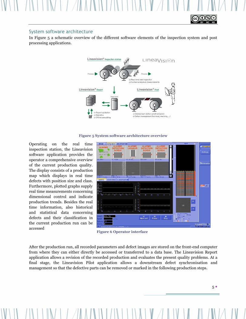
System software architecture
In Figure 5 a schematic overview of the different software elements of the inspection system and post
processing applications.
Figure 5 System software architecture overview
Operating on the real time
inspection station, the Lineavision
software application provides the
operator a comprehensive overview
of the current production quality.
The display consists of a production
map which displays in real time
defects with position size and class.
Furthermore, plotted graphs supply
real time measurements concerning
dimensional control and indicate
production trends. Besides the real
time information, also historical
and statistical data concerning
defects and their classification in
the current production run can be
accessed
After the production run, all recorded parameters and defect images are stored on the front-end computer
from where they can either directly be accessed or transferred to a data base. The Lineavision Report
application allows a revision of the recorded production and evaluates the present quality problems. At a
final stage, the Lineavision Pilot application allows a downstream defect synchronisation and
management so that the defective parts can be removed or marked in the following production steps.
Figure 6 Operator interface

6
Improved inspection solution
Structured foil inspection defect control Fraunhofer IPA developed in the ELIBAMA project macro- and micro-structured electrode foils to achieve
better wetting results and increase coating adhesion while reducing the weight of the battery when being
compared with plain electrode foils. Compared to the standard foils, the structured foil imposes two
additional inspection tasks. Firstly, to inspect the quality of regularly spaced holes (macro-structure) and
secondly to inspect the foil for defects specific to the micro-structuring process of the surface of the foils.
Inspection of macro-structure
The main source of quality variations origins from a decay of the mask quality used to generate the macro-
structure during the foil production. As the materials used as a mask wear out, the holes not fully present
or, at a later stage of mask decay, fully closed. Technical specifications stated that a 20% hole closure
should be detectable as defect. Laboratory based studies defined that ~50pixels covering the original size
of the hole area can detect this defect with sufficient accuracy. The actual imaging resolution can be
defined by considering the ideal amount of cameras as a function of macro-structure size and web width.
Tested pattern had diameter between 1mm and 200µm.
Figure 7 Defect images of foil macro-structure
For the on-line inspection of such patterns the system generates binary masks from the acquired image
which permits to exclude influences of camera noise or light source variation. The accuracy could further
be improved by using sub-pixel calculations at the border area. The 100% inspection of the surface allows
to detect defects on single structures and the repetitive defect feature informs the operator if certain parts
of the mask generating the holes are damaged.
Inspection of micro-structured surface
Fraunhofer deploys an electro-chemical process to impose a micro-structure on macro-structured foil.
Depending on the process parameters, spike like defects can develop on the surface. Those spikes need to
be detected above a certain height in order to avoid that they generate a short connection through the
active layer and the separator to the opposite electrode.
A laser triangulation based cameras system has been selected as the most suitable inspection means
considering acquisition speed, resolution requirements and a 100% inspection over the full width. In the
first system a LED based light source projecting a line of 10µm width over the length of the sample was
deployed. This type of light source was preferred as it offers a very homogeneous profile unlike laser based
sources which show so called speckle noise due to their spatial and temporal coherence. However, in

7
order to permit acceptable machine speeds at the given resolution a diode laser based source is more
suitable for an integration into the envisioned bath-to-roll process. To capture the height profile outlined
by the laser line, an area sensor based high speed 3D camera has been implemented.
The capabilities of the system have been evaluated off-line by using rod like samples mounted in a rugged
sample holder connected to a true meter which synchronised the height profile data with the movement.
Considering the image acquisition conditions, the resulting theoretical height resolution was 0.25µm due
to the ability of the camera to work with a higher precision than the optical resolution. This setting
allowed to detect height defects present on the samples kindly provided by Fraunhofer IPA.
Figure 8 Height defect detection on micro-structured electrode.
Inspection of powder coated battery electrodes Fraunhofer IPA developed a new active material coating process based on electrostatic application
techniques. As a powder is applied to the conducting electrode, this process is solvent free and offers a
tremendous factory floor-space saving as instead of a long dryer, which is used to evaporate solvent or
water from the wet coating, only a short infrared stage is needed to pre-melt the binder material.
An on-line inspection system was designed on the basis of coated samples from first laboratory test and
specifications developed in cooperation with Fraunhofer IPA. The first system (see Figure 9, right) was
installed on the demonstrator provided by INGECAL to Fraunhofer and taken into service in the
demonstration phase of the ELIBAMA project. Furthermore, a second system was mounted on the
laboratory coater at KROENERT (see Figure 9, left) to accompany temperature treatment and compacting
tests for electrostatically applied cathode layers in the framework of the demonstration phase.
Figure 9 Inspection system for electrode coating at Fraunhofer IPA (left) and Kroenert (right).

8
Linear LED light sources were deployed in both installations to enable larger camera line rates than it is
possible with linear sources based on fluorescent tubes. This was mainly necessary due to the optical and
machine direction resolution (shorter maximum exposure times at the same machine speed) and to
permit an inspection of differently strong compacted powder coatings (strong change in reflectivity
depending on binder curing and compacting pressure settings). Furthermore, this acknowledges the
possibility of higher process speeds the powder application processes and suits the forecasted machine
speed1 resulting demands for wet coating processes.
A newest generation CMOS based line-scan camera was deployed in the Fraunhofer system instead of the
normally used CCD based sensors. CMOS imaging sensors have in general better anti-blooming functions
which avoid that overexposed pixels on the sensor affect their neighbouring pixels. This function is very
valuable for a battery inspection as the contrast between coated parts (very dark) and electrode foil (shiny
and thus very bright depending on acquisition conditions) is high. The measurement and detection
accuracy on coating edges and of coating defects is higher.
Results from both installations showed that the system provides able to detect valuable defects in the
powder electrode. Figure 10 shows from the left to the right side normal surface aspect variations, non-
adhering coating, pin-holes, non-homogeneous coating (thickness variations) and a defect caused by
wrinkles in the electrode foil.
Figure 10 Inspection results from powder coated electrode material on primer.
During assembly, the capabilities of the system were also evaluated on a test roll with wet coated anode
material on a copper foil. As shown below in Figure 11, the chosen image acquisition setting with the LED
light source enables also an inspection for this electrode.
Figure 11 Cathode defect images acquired with inspection system on Fraunhofer demonstrator
1 Andrea Glawe - KROENERT, ELIBAMA Stakeholder Conference, Newcastle

9
Automatic defect classification The vision system records all optically detectable anomalies which are above a certain size and optical
contrast. Specific filters can be used to enhance the detection performance of certain anomalies or
features while eliminating inherent production variations. In a second processing step, classification rules
are deployed to discriminate within the detected anomalies defects of different types such as agglomerates
of foreign particles in an active layer process. This supervised computer learning (see principle in Figure
12, left) can either be based on manually or automatically generated classification rules. During the
project, a variety of methods (neural networks, decision tree, support vector machine, etc.) have been
evaluated concerning their ability to perform a classification in real time, complexity of implementation
and their robustness (selection of initial learning data, repeatability of results and accuracy during
inspection). Figure 12 shows in the centre a defect distribution from an electrode wet coating process used
as reference data and the resulting quality of classification for these defects on the right.
Figure 12 Principle of supervised computer learning (left), input data defect class distribution (centre) and the automatic classification result (right).
Management of multiple, independent process steps A data management solution has been developed to permits to merge inspection results in one process or
of different production steps. Thereby, for example inspection results from sequential or tandem coating
systems and also results from substrate inspection with pre coating & active layer coating can be merged
by storing them in a data base. In a first step, this system concerns only the measurement results acquired
at the different production steps. However, in a following step the system is extended to allow also the
storage of defect data and images which represent a heavier load from a data volume point of view. All
data can be then be implemented into the live inspection of a subsequent production step by for example
providing relative measurements of primer coating to active layer coating or informing the operator if a
certain defect is not caused in the current production step but actually rooted in one of the previous
production steps. Furthermore, a multi production step quality report can be generated which cumulates
the inspection results of all process steps.

10
Future developments
Continuous traceability of product quality As a further step, the industrial implementation of a coherent inspection and traceability solution which
covers the manufacturing chain from foil production to stacking and final function test can be applied.
This solution would be based on the developed data base solution for the quality reports on optical
inspection results. The integration of other sensor would enable a full scale quality report about
parameters logged during the production process. For example, the integration of local thickness
measurements performed by external optical sensors or b-gauges after and before calendering would
result in a complete overview of the anode and the cathode coating quality parameters. The results from
this quality report could then be linked with non-destructive test (NDT) results, example achieved by the
system developed by Newcastle University2 in the ELIBAMA framework or results from a post-mortem
analysis. The correlation of NDT results with the production quality parameters represents a powerful
analysis tool for the process as it allows to adjust inspection parameters according to the final
performance of the battery packs. With this tool in hand, inspection parameters of each sensor can be
finely adjusted and tailored to the specific needs of each production step. Ultimately, this would increase
the yield at each of the subsequent process steps and thus, especially on battery pack level, and would
reduce expensive scrap as only cells were implemented which were produced to most suitable quality
standards.
Implementation of multi sensor systems and 3D camera To pave the path for a full traceability, a full integration of 3D inspection results is performed, from the
structured foil production into the system, and the possibilities to control and receive data from external
sensors are augmented. While the integration of the 3D camera is straight forward, as this system is a
line-scan cameras based on real time communication using one of the standards used in machine vision,
the variety of sensor communication interfaces and protocols is rather large and sensor specific. This case
needs to be taken that signals are provided either in real time or with a known delay so that the provided
data can be logged with an encoder controlled position. Furthermore, needs to be evaluated which data is
to be implemented in a binary, pass-fail manner and which is more valuable and thus requires the actual
measurement to be stored.
2 Matthew Armstrong – University of Newcastle, ELIBAMA Stakeholder conference, Newcastle

11
Contacts
IN CORE Systèmes PARC AKTILAND - Bât. A Chemin du Lortaret 69800 SAINT PRIEST – FRANCE http://www.incore-systemes.fr
Dr. Michel Popovic - General Manager
Tel (33) 04 69 84 16 66
Mob (33) 06 14 35 20 98
Dr. Christoph Bay - R&D project manager
Tel (33) 04 69 84 16 60 Mob (33) 06 28 45 54 18
The ELIBAMA project is granted by the European Commission under the “Nanosciences,
nanotechnologies, materials & new production technologies” (NMP) Theme of the 7th
Framework Programme for Research and Technological Development.