Embed Size (px)
Citation preview

EUROPEAN ORGANISATION FOR THE SAFETY OF AIR NAVIGATION
EUROCONTROL
EUROPEAN AIR TRAFFIC MANAGEMENT PROGRAMME
EUROCONTROL Guidance Material for Approach Path
Monitor Appendix D-1: Enhancement of
APM for Geneva
Edition Number : 1.0 Edition Date : 19 May 2009 Status : Released Issue Intended for : CND Stakeholders

EUROCONTROL Guidance Material for Approach Path Monitor Appendix D-1: Enhancement of APM for Geneva
Page ii Released Issue Edition Number: 1.0
DOCUMENT CHARACTERISTICS
TITLE
EUROCONTROL Guidance Material for Approach Path Monitor
Appendix D-1: Enhancement of APM for Geneva Document Identifier Edition Number: 1.0
EUROCONTROL-GUID-129 Edition Date: 19 May 2009
Abstract Skyguide’s MSAW system, installed in Geneva, has been configured to serve two different functions. Generally, the MSAW provides an alert when an aircraft deviates significantly below the minimum vectoring altitude (MVA). The MSAW also provides an alert when an aircraft on the Geneva final approach segment deviates below a user-defined approach profile; this is in effect an Approach Path Monitor (APM) function.
The objective of this study was to compare the performance of the current Skyguide MSAW system on the final approach segment with that of a more typical APM system, in order to assess if any advantage would be gained.
This document describes the actions undertaken and the results achieved. It forms a Case Study in applying the guidance material that supports the EUROCONTROL Specification for APW, and as such is guidance material in its own right.
Keywords Safety Nets APM
Contact Person(s) Tel Unit Ben Bakker +32 2 72 91346 CND/COE/AT/AO
STATUS, AUDIENCE AND ACCESSIBILITY Status Intended for Accessible via
Working Draft General Public Intranet Draft CND Stakeholders Extranet Proposed Issue Restricted Audience Internet (www.eurocontrol.int) Released Issue Printed & electronic copies of the document can be obtained from
ALDA (see page iii)
ELECTRONIC SOURCE Path: \\HHBRUNA02\bakkerb$\QC
Host System Software Size Windows_NT Microsoft Word 10.0 5039 Kb
EUROCONTROL Guidance Material for Approach Path Monitor Appendix D-1: Enhancement of APM for Geneva
Edition Number: 1.0 Released Issue Page iii
EUROCONTROL Agency, Library Documentation and Archives (ALDA) EUROCONTROL Headquarters (50.703) 96 Rue de la Fusée B-1130 BRUSSELS Tel: +32 (0)2 729 11 52 E-mail: [email protected]
DOCUMENT APPROVAL
The following table identifies all management authorities who have successively approved the present issue of this document.
AUTHORITY NAME AND SIGNATURE DATE
Technical Manager
Ben Bakker 19-5-2009
Head of ATC Operations and Systems Unit
Martin Griffin 19-5-2009
Deputy Director Network
Development
Alex Hendriks 19-5-2009

EUROCONTROL Guidance Material for Approach Path Monitor Appendix D-1: Enhancement of APM for Geneva
Page iv Released Issue Edition Number: 1.0
DOCUMENT CHANGE RECORD
The following table records the complete history of the successive editions of the present document. EDITION NUMBER
EDITION DATE REASON FOR CHANGE PAGES AFFECTED
1.0 19-5-2009 First released issue All

EUROCONTROL Guidance Material for Approach Path Monitor Appendix D-1: Enhancement of APM for Geneva
Edition Number: 1.0 Released Issue Page v
CONTENTS
DOCUMENT CHARACTERISTICS.............................................................................ii
DOCUMENT APPROVAL..........................................................................................iii
DOCUMENT CHANGE RECORD..............................................................................iv
FOREWORD ...............................................................................................................1
1. INTRODUCTION...................................................................................................3 1.1 Overview of the Study ...............................................................................................................3 1.2 Study Objectives .......................................................................................................................3 1.3 Report Structure........................................................................................................................4
2. MSAW/APM at Geneva........................................................................................5 2.1 MSAW Polygons .......................................................................................................................5 2.2 Track Eligibility and Inhibition....................................................................................................5 2.3 MSAW/APM Performance.........................................................................................................6
3. Methodology and Tools ......................................................................................7 3.1 Overview of Analysis Methodology ...........................................................................................7 3.2 APM Optimisation Objectives ...................................................................................................7 3.3 Data Samples............................................................................................................................7 3.4 MSAW/APM Model ...................................................................................................................7
3.4.1 MSAW/APM Model............................................................................................................8
3.4.2 MSAW Conflict Detection using Polygons ......................................................................10
3.4.3 Approach Path Definitions and Conflict Detection ..........................................................11
3.4.4 MSAW/APM Alert Results Files ......................................................................................14
3.5 Google Earth™ .......................................................................................................................14
4. Analysis and Results ........................................................................................15 4.1 Initial Analysis .........................................................................................................................15
4.1.1 Situation 1........................................................................................................................17
4.1.2 Situation 2........................................................................................................................17
4.1.3 Situation 3........................................................................................................................17
4.1.4 Situation 4........................................................................................................................17

EUROCONTROL Guidance Material for Approach Path Monitor Appendix D-1: Enhancement of APM for Geneva
Page vi Released Issue Edition Number: 1.0
4.1.5 Situation 5........................................................................................................................18
4.2 The effect of raising LOWERSLOPE ......................................................................................18 4.3 The effect of increasing MAXDISTANCE................................................................................20
4.3.1 Using the JOININGHEIGHT parameter ..........................................................................21
4.4 Emulating the MSAW polygons as closely as possible using the APM funnels .....................22 4.5 Reducing MINDISTANCE .......................................................................................................23 4.6 The MSAW / APM boundary...................................................................................................25
4.6.1 Guiding Principles............................................................................................................26
4.6.2 Suggested Logic..............................................................................................................26
4.6.3 Comparison Runs............................................................................................................27
5. Conclusions.......................................................................................................30 5.1 The Analysis Method...............................................................................................................30 5.2 Comparison of APM Funnels and MSAW Polygons...............................................................30 5.3 APM parameter tuning ............................................................................................................31 5.4 The MSAW / APM Boundary ..................................................................................................31
6. Recommendations ............................................................................................32
7. References.........................................................................................................33
8. List of Abbreviations.........................................................................................34
9. Figures ...............................................................................................................35

EUROCONTROL Guidance Material for Approach Path Monitor Appendix D-1: Enhancement of APM for Geneva
FOREWORD
Skyguide have had an MSAW system operational since 1999. It is currently applied in the vicinity of Geneva and Zurich airports. The system, amongst others, provides an alert when an aircraft deviates below a user-defined approach profile; this is in effect an Approach Path Monitor (APM) function. In the first half of 2008, Skyguide and EUROCONTROL, supported by QinetiQ and Deep Blue, collaborated to study possible enhancements of the APM function. This document describes the actions undertaken and the results achieved. It forms a Case Study in applying the guidance material that supports the EUROCONTROL Specification for APM, and as such is guidance material in its own right. Note however that specific solutions identified in the document should not be adopted without performing similar analysis to determine their applicability in the target environment.
Edition Number: 1.0 Released Issue Page 1

EUROCONTROL Guidance Material for Approach Path Monitor Appendix D-1: Enhancement of APM for Geneva
Page 2 Released Issue Edition Number: 1.0

EUROCONTROL Guidance Material for Approach Path Monitor Appendix D-1: Enhancement of APM for Geneva
1. INTRODUCTION
1.1 Overview of the Study
Skyguide have had an MSAW system operational since 1999. It is currently applied in the vicinity of Geneva and Zurich airports.
Significantly, the MSAW system installed in Geneva has been configured to serve two different functions:
• Generally, the MSAW provides an alert when an aircraft deviates significantly below the minimum vectoring altitude (MVA).
• The MSAW also provides an alert when an aircraft on the Geneva final approach segment deviates below a user-defined approach profile; this is in effect an Approach Path Monitor (APM) function.
The MSAW solution that Skyguide use for the final approach segment is different in a number of respects to typical APM systems. Whereas the Skyguide MSAW uses polygons with predefined altitude limits to define an MSAW surface, in a typical APM system, the alerting threshold is defined by a funnel shape; aircraft above or below the approach funnel provoke an APM alert.
It should be noted, that the use of the acronym MSAW, in this study report, refers to not only MSAW in the general sense, but also to the part of MSAW used by Skyguide to alert on the final approach path. The acronym APM refers to the more typical type of an APM system that uses funnels.
1.2 Study Objectives
The objective of this study was to compare the performance of the current Skyguide MSAW system on the final approach segment with that of a more typical APM system, in order to assess if any advantage would be gained in implementing a typical APM solution.
Furthermore, this study examines the spatial boundary between MSAW and APM – the point at which APM should take over from MSAW during an aircraft arrival to Geneva airport.
The study is also carried out in the context of the MSAW case study (reference 1) which considers the future geographical expansion of Skyguide’s MSAW function.
Edition Number: 1.0 Released Issue Page 3

EUROCONTROL Guidance Material for Approach Path Monitor Appendix D-1: Enhancement of APM for Geneva
1.3 Report Structure
The key elements of Skyguide’s current MSAW system are described in chapter 2 of this study. The analysis method and tools, including the MSAW/APM model, are described in chapter 3. A detailed description of the steps taken in the study and the results are presented in chapter 4. Conclusions are drawn in chapter 5, and recommendations are made in chapter 6. References are in chapter 7, and a list of abbreviations is included in chapter 8.
Most of the pictures and diagrams in this report are contained in chapter 9. These pictures show, amongst other things, the MSAW polygons and APM approach funnels that were used, as well as pertinent situations.
Many of these pictures were produced using Google Earth™. The KML files used to draw the polygons, funnels and tracks can be found on www.eurocontrol.int/safety-nets if the reader wishes to examine the pictures using Google Earth™ (a free version is available at earth.google.com). The use of Google Earth™ (see section 3.5) greatly facilitated the discussions in the study team and with operational staff.
Page 4 Released Issue Edition Number: 1.0

EUROCONTROL Guidance Material for Approach Path Monitor Appendix D-1: Enhancement of APM for Geneva
2. MSAW/APM AT GENEVA
2.1 MSAW Polygons
Skyguide’s current MSAW system works on the basis of detecting aircraft tracks that penetrate predefined volumes of airspace. These MSAW volumes have been carefully defined off-line by Skyguide engineers with the assistance of experienced controllers.
The MSAW volumes for Geneva are shown in Figure 9-1. They extend to a maximum of 30 NM from the airport. Each MSAW volume is defined as a polygon with a fixed ceiling height. The majority of the coverage is based on pre-defined Minimum Vectoring Altitudes (MVAs) with each MSAW polygon ceiling set 350ft below the respective MVA.
In addition, Skyguide employ the MSAW function as an Approach Path Monitor (APM). This has been achieved by defining numerous small MSAW polygons along the line of the runway final approach paths (GVA RWY 23 and 05). When viewed in 3D, these small polygons resemble a staircase. See Figure 9-2 and Figure 9-3. These small polygons have been constructed taking into account the defined procedural approach for each runway.
No prediction is applied in the MSAW system. If an eligible aircraft penetrates one of the defined MSAW volumes then an alert is immediately generated which may then be displayed to the controller, depending on whether the controller has already manually inhibited the track from MSAW alerting.
2.2 Track Eligibility and Inhibition
An aircraft is eligible for MSAW processing if it is correlated with a flight plan, and its SSR code is not on a pre-defined VFR or Military (MIL) code list. On the face of it, this scheme should work well. However, there is sometimes a mismatch between the flight rules for an aircraft and the allocated SSR code. For example, a flight may be allocated an SSR code which indicates IFR, yet the flight takes off VFR joining IFR later (This situation includes aircraft taking off from Annemasse, in France, as well as Swiss airports local to Geneva). In other cases a flight may be squawking an SSR code indicating IFR but may then “leave” make a VFR approach, and as a consequence proceed intentionally below the MVA into an MSAW polygon.
The controller has the facility to inhibit MSAW for selected tracks. This is usually done for visual approaches or departures, and VFR traffic squawking an IFR SSR code (joining flights). The controller knows these flights will remain close to the terrain to have visual references, and therefore an MSAW alert would just be a distraction.
Edition Number: 1.0 Released Issue Page 5

EUROCONTROL Guidance Material for Approach Path Monitor Appendix D-1: Enhancement of APM for Geneva
2.3 MSAW/APM Performance
The current MSAW system generates around 15 alerts per day on average. Normally, however, not all of these would result in an alert (visual or audible) at the CWP, since the controller has the facility to disable MSAW for specific tracks, and also to acknowledge an alert that is in progress. (In the case of MSAW being disabled, the track label indicates this so the controller remains aware that MSAW is disabled for this particular track).
Furthermore, the number of MSAW alerts on the final approach segment represents only a very small fraction of the total number of MSAW alerts, and consequently the current alert rate here is not of great concern to Skyguide.
Nevertheless, this study does measure alert rates for MSAW and APM, to compare the two systems, whilst also examining issues related to the timing and appropriateness of alerts. The study goes on to examine the spatial boundary between MSAW and APM.
Page 6 Released Issue Edition Number: 1.0

EUROCONTROL Guidance Material for Approach Path Monitor Appendix D-1: Enhancement of APM for Geneva
3. METHODOLOGY AND TOOLS
3.1 Overview of Analysis Methodology
The central theme in this study was the use of a fast time MSAW/APM model to measure and compare the performance of both MSAW (using polygons) and APM (using funnels).
The work was carried out in a series of steps. The precise steps and the results of each stage of the analysis are explained in detail in chapter 4.
3.2 APM Optimisation Objectives
Essentially, the object of APM design and optimisation is to maximise the number of conflicts which are alerted with adequate warning time and minimise the number of nuisance alerts.
In APM, the correct balance between the warning time and the nuisance alert rate is usually achieved by careful adjustment of the defined APM approach funnels. However, on final approach, there may be a very small time between a detected deviation below the glide slope and a potential CFIT. Therefore, the optimum balance between these to competing objectives may be difficult to achieve without compromising on either the warning time or the nuisance alert rate to some extent.
Many APM systems are capable of alerting for deviation above as well as below the nominal approach slope. However, for this study, only deviations below the nominal approach slope were deemed necessary, and the “deviation above the glide slope” aspect of APM was not considered.
3.3 Data Samples
The data used for this study comprised radar track recordings made at Skyguide premises in Geneva. The sample period covered 25 days in September and October 2006. Not all the recorded days were complete, so the total recording duration was in fact around 23 days, 5½ hours.
3.4 MSAW/APM Model
During the course of this study, the track recordings were input into the fast-time MSAW/APM model in order to measure the performance of the current MSAW system alongside the APM system. The performance results of each run were recorded in text files.
The model was written in the C programming language, running on a PC under the Fedora operating system.
Edition Number: 1.0 Released Issue Page 7

EUROCONTROL Guidance Material for Approach Path Monitor Appendix D-1: Enhancement of APM for Geneva
The inputs to and outputs from the MSAW/APM model are shown diagrammatically in Figure 3-1 below. The text results files were of primary importance to the study, whilst the ASTERIX Cat004 files were not used here.
Tracks
ASTERIX Cat 030
MSAW/APM Model
MSAW Polygons,
APM Funnels and Parameters
Alerts ASTERIX Cat 004
MSAW/APM Alert Results
(Text)
Figure 3-1 Inputs to and outputs from the MSAW/APM Model
3.4.1 MSAW/APM Model
The MSAW/APM model is a simulation tool capable of modelling not only the current Skyguide MSAW system, but also APM, as well as MSAW in a variety of other configurations, including the use of digital terrain elevation data (DTED). The model runs in fast time, generating a week’s worth of results typically in less than thirty minutes.
The processing stages in the MSAW/APM model are shown in Figure 3-2 below:
Page 8 Released Issue Edition Number: 1.0

EUROCONTROL Guidance Material for Approach Path Monitor Appendix D-1: Enhancement of APM for Geneva
System Tracks
DTED Conflict Detection
Polygon Conflict
Detection
APM Conflict Detection
Polygon Alert Confirmation
DTED Alert Confirmation
APM Alert Confirmation
Polygon Alerts DTED Alerts APM Alerts
Figure 3-2 Processing Stages in the MSAW/APM model
The DTED Conflict Detection in the MSAW/APM model was in fact unused in the initial steps of the study, but was activated later on when consideration was given to the appropriate MSAW/APM spatial boundary.
Various files defining essential parameters, the MSAW polygons, the APM funnels and a list of SSR codes were input into the MSAW/APM model each time it was run.
An extract from the MSAW polygon definition file is shown in Figure 9-4. The polygon definition file contains the polygons used for MSAW conflict detection. Each polygon definition includes the name of the polygon, a ceiling altitude in feet, and a list of points defined in latitude and longitude.
A sample APM funnel definition file is shown in Figure 9-5. The funnel definition file contains the approach funnels used for APM conflict detection. The most fundamental parameters in the funnel definition are the ground altitude, the upper and lower elevation angles, and the two latitude and longitude coordinates that define the lateral position and orientation of the funnel. The funnel definition and APM conflict detection are described in detail in section 3.4.3.
Edition Number: 1.0 Released Issue Page 9

EUROCONTROL Guidance Material for Approach Path Monitor Appendix D-1: Enhancement of APM for Geneva
The parameters to be applied were specified in a simple text file, an example of which is shown in Figure 9-6. The parameters include activation flags for various parts of the MSAW/APM model, as well as the critical conflict detection thresholds.
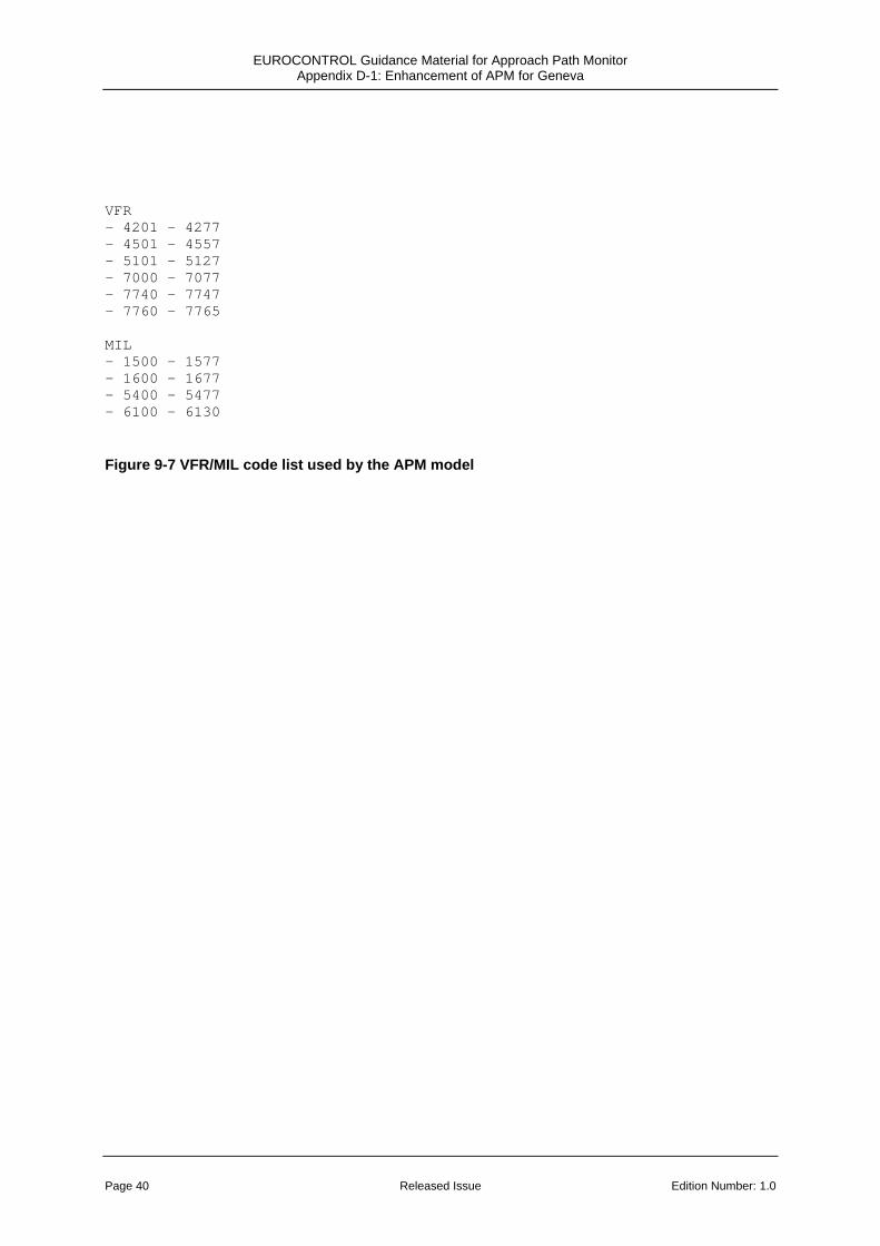
The full VFR/MIL code list is shown in Figure 9-7. This comprises a number of SSR code blocks that are automatically suppressed from MSAW/APM alerting.
The model generated two types of output; the alert results as a text file (described in section 3.4.2) and a binary file of ASTERIX Category 4 (Safety Nets) records, which can be used in other tools. However, in this study, only the text results files were used.
3.4.2 MSAW Conflict Detection using Polygons
MSAW conflict detection against polygons as implemented in the current Skyguide MSAW system is illustrated in Figure 3-3 below:
Terrain
MSAW Polygon
350ft
MVA
Figure 3-3 Illustration of MSAW conflict detection using polygons
Page 10 Released Issue Edition Number: 1.0

EUROCONTROL Guidance Material for Approach Path Monitor Appendix D-1: Enhancement of APM for Geneva
The MSAW surface is typically (though not always) defined 350ft below the MVA. The MVA has to assure 1000ft clearance above the highest obstacle with a 5NM lateral buffer in non-mountainous terrain. In mountainous terrain this clearance is increased to 2000ft. Since the MVA varies through the airspace, the MSAW surface consists of numerous polygons. An MSAW alert is triggered whenever an MSAW eligible aircraft enters one of the pre-defined polygons, irrespective of whether the aircraft entered through the wall or ceiling.
Of specific interest to this study are the MSAW polygons that are defined for the final approach segment, and which take into account the expected approach paths to the Geneva runway (05 and 23) rather than any MVAs.
3.4.3 Approach Path Definitions and Conflict Detection
The APM part of the MSAW model allows APM approach funnels to be defined for each runway of interest. Each approach path definition has a name identifying the airport and runway, and parameters that define a volume or funnel which describe the limits of the nominal final approach path.
The shape of the approach path definition is much the same as in the reference APM description (reference 2). However, there are some additional features, in the APM model which add some flexibility to the reference APM system.
CENTRELINELEFT
CENTRELINERIGHT MINDISTANCE
HEADINGTOL LATERALANGLE TOUCHDOWN
MAXDISTANCE
OUTERMARKER
Figure 3-4 Plan View of APM Approach Path Definition
Edition Number: 1.0 Released Issue Page 11

EUROCONTROL Guidance Material for Approach Path Monitor Appendix D-1: Enhancement of APM for Geneva
The TOUCHDOWN point and the OUTERMARKER point between them define the expected touchdown point for aircraft landing on the particular runway and the orientation of the approach path.
LATERALANGLE defines the angular extent of the lateral area, and MINDISTANCE and MAXDISTANCE complete the lateral area definition.
Aircraft are not processed by APM if they are less than MINDISTANCE or more than MAXDISTANCE from the runway touchdown.
Furthermore, aircraft are not processed by APM if they are more than CENTRELINELEFT to the left of the extended runway centre line, or more than CENTRELINERIGHT to the right of the extended runway centre line. This feature was added because of a single nuisance alert generated by the MSAW/APM model when an aircraft used a grass strip, which lies parallel to the concrete runway at Geneva. The feature also allows MSAW to function in the event that an aircraft deviates laterally from the approach path towards the Jura (The Jura mountain range is quite close to the expected approach path). In general, however, this feature is thought to be especially applicable to parallel runway situations.
If the aircraft is within the lateral area and the heading of the aircraft is within HEADINGTOL of the nominal approach path, then the aircraft is deemed to be on final approach. It is then subject to vertical and lateral APM alerts as described further.
If the aircraft is on the lateral final approach path then the current vertical position is considered relative to the approach path shape, shown below:
Page 12 Released Issue Edition Number: 1.0

EUROCONTROL Guidance Material for Approach Path Monitor Appendix D-1: Enhancement of APM for Geneva
JOININGHEIGHT
OVERFLIGHTALT
GROUNDALT
UPPERSLOPE
MAXDISTANCE
MINDISTANCE
LOWERSLOPE
TOUCHDOWN
Figure 3-5 Altitude View of APM Approach Path Definition
For a start, some aircraft can be automatically discounted because they are assumed to be flying over the airport. Aircraft above OVERFLIGHTALT are not considered by APM.
The vertical section of the volume is defined by GROUNDALT, TOUCHDOWN, LOWERSLOPE, UPPERSLOPE, JOININGHEIGHT, MINDISTANCE and MAXDISTANCE as shown in the altitude view diagram.
Many aircraft intercept the glide slope whilst they are in level flight; The JOININGHEIGHT parameter allows the approach volume definition to take this into account as part of the expected approach procedure.
If APMActivateBelowGlideSlope is set in the parameter file and the aircraft’s current vertical position is below LOWERSLOPE then a below glide slope alert is generated by the MSAW/APM model.
Edition Number: 1.0 Released Issue Page 13
EUROCONTROL Guidance Material for Approach Path Monitor Appendix D-1: Enhancement of APM for Geneva
If APMActivateAboveGlideSlope is set in the parameter file and the aircraft’s current vertical position is above UPPERSLOPE then an above glide slope alert is generated by the MSAW/APM model.
3.4.4 MSAW/APM Alert Results Files
The MSAW/APM results file provides statistics such as the number of MSAW and APM alerts as well as pertinent information relating to each alert including the identity and location of the flight, and the time and duration of the alert.
Additional information for the MSAW alerts includes the polygon that has been infringed at the start of the alert, whereas each APM alert identifies whether the aircraft is above or below the expected approach path and the distance to the runway threshold at the start of the alert.
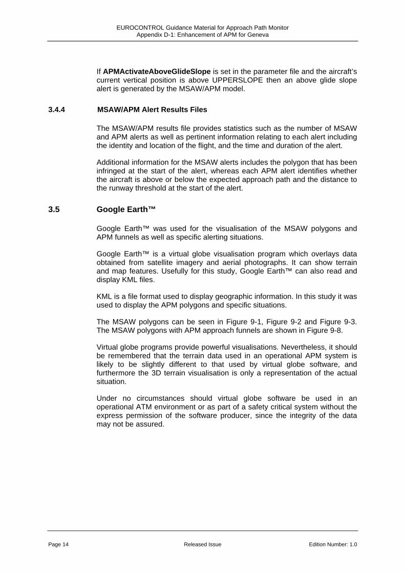
3.5 Google Earth™
Google Earth™ was used for the visualisation of the MSAW polygons and APM funnels as well as specific alerting situations.
Google Earth™ is a virtual globe visualisation program which overlays data obtained from satellite imagery and aerial photographs. It can show terrain and map features. Usefully for this study, Google Earth™ can also read and display KML files.
KML is a file format used to display geographic information. In this study it was used to display the APM polygons and specific situations.
The MSAW polygons can be seen in Figure 9-1, Figure 9-2 and Figure 9-3. The MSAW polygons with APM approach funnels are shown in Figure 9-8.
Virtual globe programs provide powerful visualisations. Nevertheless, it should be remembered that the terrain data used in an operational APM system is likely to be slightly different to that used by virtual globe software, and furthermore the 3D terrain visualisation is only a representation of the actual situation.
Under no circumstances should virtual globe software be used in an operational ATM environment or as part of a safety critical system without the express permission of the software producer, since the integrity of the data may not be assured.
Page 14 Released Issue Edition Number: 1.0

EUROCONTROL Guidance Material for Approach Path Monitor Appendix D-1: Enhancement of APM for Geneva
4. ANALYSIS AND RESULTS
4.1 Initial Analysis
The first aim of the study was to make an initial comparison of APM and MSAW alerts on the final approach to Geneva.
The MSAW/APM model was run using a subset of the current MSAW polygon definitions (i.e. those on the final approach path) and an initial definition of the APM approach funnels for runways 05 and 23 at Geneva. For a direct comparison of the MSAW polygons and APM, the APM funnels were designed to extend to the same range as the MSAW polygons. That is, from 3NM to 16NM for runway 05 and from 3NM to 9NM for runway 23. The APM LOWERSLOPE parameter was set to 2°, which allowed for a 1 degree deviation from the glide slope before an alert was raised.
The APM funnel definitions are listed in Figure 9-5. Figure 9-8 shows the MSAW polygons and APM funnels together on the same picture, with the polygons being a darker blue colour where they are above the lower slope of the APM funnel. It can be seen that the MSAW polygons are higher than the APM lower slope for the whole of the defined runway 05 approach, but for runway 23, they only jut above the APM lower slope in a few places.
Note that the APM polygons in the figures show the lateral boundary of the funnel, but without CENTRELINELEFT and CENTRELINERIGHT being applied. [In the MSAW/APM model, the tests for an aircraft lying within the funnel and for an aircraft lying within the centre line tolerances are done separately]. Hence in an aircraft is only eligible for APM processing if:
• it is within the lateral plan of the funnel (as shown in Figure 9-8)
• it is within CENTRELINELEFT and CENTRELINERIGHT of the extended runway centre line (in this study, within 0.6NM)
• it’s heading is aligned with the runway (within HEADINGTOL of the expected approach heading)
The model was run on the full 25 day data sample, processing flights that were correlated with a flight plan, and that had an IFR SSR code (i.e. the same eligibility criteria as currently used for MSAW at Geneva). As well as logging the alerts, the model also recorded the number of “qualifying tracks” – those tracks that were in an approach funnel and laterally lined up with the runway (i.e. qualifying for vertical consideration against the APM funnel). Over the whole data sample the number of qualifying tracks for runway 05 was 64888, and for runway 23, 197330. This equated to 25% of flights landing on runway 05, and 75% landing on runway 23. Consequently, for this data sample, around three times as many alerts were expected for runway 23, compared to runway 05.
Edition Number: 1.0 Released Issue Page 15

EUROCONTROL Guidance Material for Approach Path Monitor Appendix D-1: Enhancement of APM for Geneva
There were only five alerting situations for the entire data sample. There were four situations which generated an MSAW (polygon) and an APM alert, and an additional situation which generated an MSAW alert only. The mean daily alert rate for APM was 0.17, and for MSAW was 0.22.
The five situations are depicted in Figure 9-9, Figure 9-10, Figure 9-11, Figure 9-12 and Figure 9-13. In the figures, the MSAW alerts are shown in white, APM alerts in red, and simultaneous (MSAW and APM) alerts are in pink.
The results are also summarised in Table 4-1 below. The deviation below the glide slope was computed by comparing the aircraft altitude to the Geneva glide slope elevation of 3°. The distance of the aircraft above the local terrain was computed using the terrain spot height available from Google Earth™.
Alerting Situation No. 1 2 3 4 5
Approx. Time of Day 14:49 14:05 09:19 15:23 11:40
SSR Code 5715 3224 6750 3106 2320
Call Sign N525PM N45WF HBGHD DGX960 HBLTL
Runway 05 23 23 05 23
Distance to Runway 9.2NM 3.0NM 8.9NM - 3.1NM
Aircraft Altitude 3316ft 1989ft 2989ft - 1989ft
Deviation below Glide Slope
1021ft 376ft 1252ft - 408ft
At start of APM Alert:
Distance above local terrain
1895ft 772ft 1755ft - 772ft
Distance to Runway 11.3NM 3.0NM 8.9NM 11.5NM 3.1NM
Aircraft Altitude 4316ft 1989ft 2989ft 4330ft 1989ft
Deviation below Glide Slope
688ft 376ft 1252ft 738ft 408ft
At start of MSAW Alert:
Distance above local terrain
1688ft 772ft 1755ft 1210ft 772ft
Table 4-1 Table Summarising the five alerting situations
Page 16 Released Issue Edition Number: 1.0

EUROCONTROL Guidance Material for Approach Path Monitor Appendix D-1: Enhancement of APM for Geneva
4.1.1 Situation 1
In situation 1 the MSAW (polygon) alerts first at 11.3NM from touchdown, as shown by the white track markers. The APM does not alert at this stage because the aircraft is above the lower slope of the APM funnel and furthermore the track heading is more than HEADINGTOL (8°) from the final approach heading. The markers turn pink when the APM alert triggers, at 9.2NM from the runway, indicating that both MSAW and APM alerts are now in progress.
At the time that the MSAW alert triggers, it can be seen clearly in Figure 9-9 that the aircraft has just flown over a ridge, although it is very doubtful that there is any significant risk of CFIT at this stage.
4.1.2 Situation 2
In situation 2 the aircraft just clips the MSAW and APM surface at 3NM from the runway. At this point there is more than a minute until touchdown, so there would in principle be plenty of time for communication between the controller and the pilot. It is anticipated that the APM funnel could be extended towards the runway by about 1NM. However, there will be a limit as to how close to the runway APM can effectively operate, due to the limited time available to resolve the situation, and an anticipated increase in the number of nuisance alerts. (Closer to the runway, the funnel becomes narrower, and small errors in the computed vertical track position can provoke nuisance alerts).
4.1.3 Situation 3
In situation 3 the MSAW and APM alerts trigger simultaneously when the aircraft enters the lateral limits of the corresponding volumes. One thing to note in this situation is that the trigger of the alert is also coincident with a small but significant jump in the vertical track. This suggests that the track is in error either just before or just after the jump, and one therefore cannot be certain that the aircraft deviated from the glide slope by the extent that has been recorded.
4.1.4 Situation 4
Situation 4 is quite similar to situation 1, except that in this case there is no APM alert. The MSAW alert occurs just as the aircraft is flying over the ridge (slightly earlier than in situation 1). Again, the MSAW alert is irrelevant in relation to the ridge, because there is no risk of CFIT at this point; the alert only has value as a warning of deviation from the expected glide slope path. At the point the alert triggers the aircraft is 738ft below the expected glide slope path and 1210ft above the terrain.
Edition Number: 1.0 Released Issue Page 17

EUROCONTROL Guidance Material for Approach Path Monitor Appendix D-1: Enhancement of APM for Geneva
4.1.5 Situation 5
Situation 5 is very similar to situation 2, where the aircraft just penetrates the relevant MSAW and APM surfaces.
4.2 The effect of raising LOWERSLOPE
For aircraft executing a precision approach to Geneva (i.e. following the ILS), a one degree glide slope deviation could be considered very large.
Typically, the Course Deviation Indicator (CDI) in the aircraft cockpit would indicate a vertical deviation from the glide slope in 0.1 degree increments (dots), up to a maximum scale of +/- 0.5° (i.e. +/- 5 dots). A one degree deviation is therefore off the scale of a CDI.
Nevertheless, the threshold for triggering an APM alert does also need to take account of a number of factors, including:
• The nominal vertical profile for aircraft on precision and non-precision approach
• Allowance for normal vertical fluctuations due to aircraft avionics
• Allowance for the surveillance data precision (i.e. 25ft or 100ft in height) and tracker accuracy
• Allowance for the precision of the applied correction for QNH (approx 30ft for 1 millibar)
With LOWERSLOPE set at 2.0°, the most probable circumstances that would lead to an alert would be an aircraft flying a non-precision approach. Conversely, aircraft flying a precision approach would be much less likely to provoke an APM alert.
The MSAW/APM model was rerun, adjusting the LOWERSLOPE parameter each time in order to see what effect this would have on the number and type of APM alerts The LOWERSLOPE parameter for APM was first raised to 2.25°, then to 2.5° for both runway approach funnels.
The results are summarised in below:
Page 18 Released Issue Edition Number: 1.0

EUROCONTROL Guidance Material for Approach Path Monitor Appendix D-1: Enhancement of APM for Geneva
Number of APM alerts by value of LOWERSLOPE parameter
0
5
10
15
20
25
30
35
2 2.25 2.5
LOWERSLOPE / degrees
Ale
rts o
ver d
ata
sam
ple
(23.
23 d
ays)
Runway 23Runway 05
Figure 4-1 The number of APM alerts as a function of
the LOWERSLOPE parameter
An additional run was made with LOWERSLOPE increased to 2.75°. This resulted in 178 alerts for runway 05 and 208 alerts for runway 23. [Note: These results are omitted from the graph to avoid compression of the scale]
The timing of the four common alerts for the various runs of the MSAW/APM model is compared in the table below.
Edition Number: 1.0 Released Issue Page 19

EUROCONTROL Guidance Material for Approach Path Monitor Appendix D-1: Enhancement of APM for Geneva
Alerting Situation No. 1 2 3 5
Time of Day 14:49 14:05 09:19 11:40
SSR Code 5715 3224 6750 2320
Call Sign N525PM N45WF HBGHD HBLTL
Runway 05 23 23 23
LOWERSLOPE = 2.0 (Baseline run)
Distance to runway 9.2NM 3.0NM 8.9NM 3.1NM
Distance to runway 9.4NM 3.9NM 8.9NM 3.4NMLOWERSLOPE = 2.25
Time advantage over baseline
4s 24s none 4s
Distance to runway 9.4NM 5.0NM 8.9NM 3.6NMLOWERSLOPE = 2.5
Time advantage over baseline
4s 52s none 8s
Table 4-2 Table comparing the four common alerts for various values of LOWERSLOPE
The table shows that there is some extra warning time to be gained by increasing the LOWERSLOPE parameter. The potential gain is quite considerable for situation 2. However, the extra warning time that can be gained for situation 1 is limited because the aircraft has only just turned onto the localiser at 9.4NM. Before this time, the aircraft heading exceeds the 8 degree tolerance allowed for by the current approach path definition.
There is no warning time to be gained for situation 3, since the timing of the alert is constrained by the MAXDISTANCE parameter (8.93NM) set for runway 23.
4.3 The effect of increasing MAXDISTANCE
Initial examinations showed that at least one potential APM alert was constrained by the MAXDISTANCE parameter being set to 8.93NM.
The next step was to consider the potential to extend the coverage of the APM system to a larger range, by increasing MAXDISTANCE for the two approach funnel definitions.
Page 20 Released Issue Edition Number: 1.0

EUROCONTROL Guidance Material for Approach Path Monitor Appendix D-1: Enhancement of APM for Geneva
Figure 9-14 shows a sample of nine different approach paths to Geneva runway 23. Runway 23 is an approach over Lake Geneva, and the latest point where aircraft shall be lined up is PETAL at 4000ft. In the figure, the nine aircraft can be seen lining up with the runway – before PETAL (at around 10NM from touchdown). Indeed, some of the approaches to Geneva are lined up well before PETAL.
The MAXDISTANCE parameter was set to 17NM for both final approach funnels, and the MSAW/APM model was run in order to see what effect this extension would have on APM performance. The LOWERSLOPE parameter was set to 2.25NM, which was judged to offer a reasonable timing of alerts without overly affecting the alert rate.
For this run there were 83 alerts for runway 23 (mean = 3.57 per day) and just one alert for runway 05. On retrospect, the result should have been expected. For geographical reasons, there are different approach profiles for the two runways. Runway 23 is an approach over the lake and the aircraft may be at 4000ft. For runway 05, the mountains are closer to the final approach path and so (unless a visual approach is performed) the aircraft have to be kept higher and lined up on final further away at 6000ft.
4.3.1 Using the JOININGHEIGHT parameter
An examination of the 83 alerts showed the new alerts occurred at least 10NM from the runway threshold, with the aircraft broadly between 3900ft and 5000ft. However, according to the procedure for runway 23, aircraft could be at 4000ft by PETAL (10NM). Simply extending the funnels was introducing a lot of nuisance alerts, and it was clear that if APM was to be applied beyond 10NM of runway 23, then the height at which aircraft joined the glide slope would have to be taken into account.
For the next run, the JOININGHEIGHT parameter for runway 23 was set to 3850ft, to reduce the number of alerts for aircraft between 10.4NM and 17NM.
For this run the number of alerts for runway 23 was successfully reduced to 12 (with still just 1 alert for runway05).
The timing of the four common APM alerts for the latest run of the MSAW/APM model was re-examined, and is shown in the table below.
Edition Number: 1.0 Released Issue Page 21

EUROCONTROL Guidance Material for Approach Path Monitor Appendix D-1: Enhancement of APM for Geneva
Alerting Situation No. 1 2 3 5
Time of Day 14:49 14:05 09:19 11:40
SSR Code 5715 3224 6750 2320
Call Sign N525PM N45WF HBGHD HBLTL
Runway 05 23 23 23
Distance to runway 9.4NM 3.9NM 12.2NM 3.4NMJOININGHEIGHT = 3850ft
Time advantage over baseline
4s 24s 75s 4s
Table 4-3 Table presenting the four common alerts when JOININGHEIGHT is set to 3850ft
The alert for situation 3 was previously limited by the MAXDITANCE parameter (set to 8.93NM). The extension of the MAXDISTANCE parameter had allowed this APM alert to trigger considerably earlier, 75s earlier than in the baseline run.
4.4 Emulating the MSAW polygons as closely as possible using the APM funnels
It was noticed at this point that the current MSAW surface (defined by polygons) appeared to offer a reasonably low alert rate. This was no doubt due to the care and attention that had been dedicated to designing the current MSAW surface. As an experiment, the MSAW/APM model was run with the APM approach funnels defined to match as closely as possible the MSAW polygons out to 17NM.
The parameters for the APM funnels were set to the following values.
Runway 05 Runway 23
LOWERSLOPE 2.35° 2.0°
MAXDISTANCE 17NM 17NM
JOININGHEIGHT 4850ft 3750ft
Table 4-4 APM parameter values used to (crudely) emulate the MSAW polygons
Page 22 Released Issue Edition Number: 1.0

EUROCONTROL Guidance Material for Approach Path Monitor Appendix D-1: Enhancement of APM for Geneva
The number of alerts over the data sample was 3 for runway 05 and 5 for runway 23. The result shows that the combination of reducing the LOWERSLOPE to 2.0° and JOININGHEIGHT to 3750ft significantly reduced the number of alerts for runway 23.
The timing of the four common alerts for the various runs of the MSAW/APM model is compared in the table below. The timing of the alerts is not very different to the original baseline run, except for situation 3, which is still able to alert early due to the extended MAXDISTANCE parameter.
Alerting Situation No. 1 2 3 5
Time of Day 14:49 14:05 09:19 11:40
SSR Code 5715 3224 6750 2320
Call Sign N525PM N45WF HBGHD HBLTL
Runway 05 23 23 23
Distance to runway 9.4NM 3.0NM 11.5NM 3.1M APM resembling the Polygons Time advantage over
baseline 4s none 59s none
Table 4-5 Table presenting the four common alerts when APM is set to resemble
the MSAW polygons
4.5 Reducing MINDISTANCE
Having examined the maximum distance to which the APM funnel could be extended, it was then of interest to see how close to the runway threshold APM could remain effective. It is inevitable that there will be a limit as to how close to the runway APM can remain an effective safety net.
Firstly, closer to the runway, the defined funnel becomes narrower, and there are likely to be more nuisance alerts. This is not to say that aircraft are unduly deviating from the approach path here, but the limited precision of the vertical data (mode S = 25ft, Mode C = 100ft), and unavoidable limitations in vertical tracking accuracy will combine, and occasional nuisance alerts will result. The narrower the funnel becomes, the more likely it is that nuisance alerts will arise.
Secondly, there will be a point when time is so short before touchdown that the controller will not be able to give a useful instruction to an aircraft if he were to receive an APM alert.
Edition Number: 1.0 Released Issue Page 23

EUROCONTROL Guidance Material for Approach Path Monitor Appendix D-1: Enhancement of APM for Geneva
In order to test the effectiveness of APM at distances closer to the runway, the MINDISTANCE parameter was varied from 3NM to 1NM in increments of 0.5NM. In all of these runs, the other parameters remained static at the values set in Table 4-4. The number of resulting APM alerts are shown in Figure 4-2 below:
The number of APM alerts vs. the MINDISTANCE parameter
5 7 8 921
4 5 8
27
89
0
20
40
60
80
100
120
3 2.5 2 1.5 1
MINDISTANCE (NM)
Num
ber o
f ale
rts
of th
e da
ta s
ampl
e
Runway 05Runway 23
Figure 4-2 The number of APM alerts vs. MINDISTANCE
As the MINDISTANCE parameter is reduced, the number of APM alerts increases quite rapidly. These alerts are due to the causes already described.
Figure 4-3 shows the density of alerts along the final approach segment, essentially by plotting the distance from the runway threshold of each alert for each runway approach.
The results indicate quite clearly a drastic increase in the number of APM alerts when MINDISTANCE is reduced below 2NM. These alerts are much more likely a nuisance, than truly wanted alerts. With the data set used, even a small decrease in MINDISTANCE to, say, less than 2.75 NM would increase the alert rate. In conclusion, it would appear that Skyguide’s original choice to continue MSAW coverage down to 3NM from the runway was fairly well judged.
Page 24 Released Issue Edition Number: 1.0

EUROCONTROL Guidance Material for Approach Path Monitor Appendix D-1: Enhancement of APM for Geneva
Distance from runway at start of each APM alert
0
1
2
3
4
5
6
7
8
9
10
11
12
13
Runway 05 Runway 23
Dis
tanc
e fr
om th
resh
old
(NM
)
Figure 4-3 The distance from the runway threshold for each APM alert
4.6 The MSAW / APM boundary
At the start of this case study, Skyguide raised the issue of the MSAW / APM boundary – the point on the final approach where APM should take over from conventional MSAW.
The MSAW Case Study (reference 1) used simple inhibition volumes around Geneva and Lausanne airports to reduce the number of nuisance alerts. Without these, there would have been an alert against the terrain for virtually every airport arrival. Figure 9-15 shows the inhibition volume that was used around Geneva.
The use of APM approach funnels and associated logic provides an opportunity to replace the inhibition volumes with a slightly more complex rule set for suppressing MSAW alerts on final approach.
Edition Number: 1.0 Released Issue Page 25

EUROCONTROL Guidance Material for Approach Path Monitor Appendix D-1: Enhancement of APM for Geneva
4.6.1 Guiding Principles
With careful consideration, it is possible to formulate a few guiding principles for defining the points in space where MSAW should be active, where APM should be active and where neither should be active. Some are suggested here:
1. The amount of time in an aircraft’s flight when it has no MSAW or APM protection should be minimised where practical. i.e.
a. There should be no ‘gap’ between MSAW and APM
b. A combined MSAW/APM solution should operate as close to the runway threshold as possible, bearing in mind practical limitations (as described in section 4.5).
c. Aircraft on the airport surface should in all circumstances be excluded from MSAW/APM processing – thus an MSAW inhibition volume for airports is still required even when APM is used. (It may be necessary for the dimensions of the volume to encompass not only the genuine tracks, but also reflected tracks and other common errors in the track position for aircraft on the ground.)
2. APM should take over from MSAW at the appropriate moment in the aircraft’s trajectory.
a. Since aircraft would in most circumstances align with the runway before following the appropriate approach slope, it is suggested that APM should only take over from MSAW when the aircraft is aligned with the runway.
4.6.2 Suggested Logic
A simple algorithm was designed to define the MSAW/APM boundary and for MSAW suppression, based upon the guiding principles described above. The algorithm is presented in Figure 4-4 below:
Page 26 Released Issue Edition Number: 1.0

EUROCONTROL Guidance Material for Approach Path Monitor Appendix D-1: Enhancement of APM for Geneva
Is the aircraft in the lateral bounds of an APM funnel and lined up with the runway (i.e. heading within HEADINGTOL)?
Track for consideration
Execute APM
Is the aircraft inside an MSAW suppression area
(e.g. very close to an airport)?
Execute neither
Execute MSAW
yes
no
no
yes
Figure 4-4 A simple algorithm to define the APM/MSAW interface
4.6.3 Comparison Runs
An assumption was made that a future MSAW system would used DTED data for conflict detection, and an APM system based on funnels. To test the new logic, the MSAW/APM model was run twice.
For the first run, the original inhibition volumes were used to suppress the DTED alerts. The inhibition volume around Geneva airport is shown with the APM funnels in Figure 9-15.
For the second run, the logic described in Figure 4-4 was used, with the inhibition volume around Geneva reduced in size as shown in Figure 9-16.
Edition Number: 1.0 Released Issue Page 27

EUROCONTROL Guidance Material for Approach Path Monitor Appendix D-1: Enhancement of APM for Geneva
In both runs, the following values for APM funnels were used:
Runway 05 Runway 23
LOWERSLOPE 2.35° 2.0°
MINDISTANCE 3NM 3NM
MAXDISTANCE 17NM 17NM
JOININGHEIGHT 4850ft 3750ft
HEADINGTOL 8° 8°
Apart from the difference in the size and shape of the volumes, the second run of the model further required the aircraft to be within HEADINGTOL (8°) of the runway final approach path in order suppress any DTED alerts.
The results are summarised in the table below:
Original Logic Test Logic
APM alerts 9 9
MSAW (DTED) alerts 55 64
Over the data sample, the test logic yielded 9 more DTED alerts than the original inhibition volumes. Two of these new alerts are shown in Figure 9-17 and Figure 9-18. They show the aircraft turning relatively late onto the Geneva final approach, with a significant descent rate, and consequently producing a nuisance DTED alert.
It was considered that at the time of these particular DTED alerts, it would be better to compare the aircraft’s position against the expected approach path (APM), rather than to produce a DTED alert. The easiest way to achieve this was to widen the HEADINGTOL criterion for considering aircraft on final approach.
In increasing HEADINGTOL, what would essentially happen is that more aircraft would be considered for APM, and fewer would be considered for MSAW (using DTED). Whilst the number of nuisance DTED alerts could be expected to decrease, there may also be an unforeseen penalty on APM performance.
Page 28 Released Issue Edition Number: 1.0

EUROCONTROL Guidance Material for Approach Path Monitor Appendix D-1: Enhancement of APM for Geneva
Three further runs of the MSAW/APM model were made with HEADINGTOL increased to 10°, 15° and 20°. The results of these runs are summarised in the table:
HEADINGTOL 10° 15° 20°
APM alerts 9 9 10
MSAW (DTED) alerts 55 48 46
There is no doubt that increasing the HEADINGTOL parameter was effective in reducing the number of MSAW (DTED) alerts in the vicinity of Geneva. A sample of the situations where DTED alerts that are suppressed in increasing the HEADINGTOL from 8° to 20° are shown in Figure 9-19 to Figure 9-21.
Setting HEADINGTOL to 20° introduced an extra APM alert, which is shown in Figure 9-22; It shows the APM alert for an aircraft on approach to Annemasse airport, which is momentarily lined up with the Geneva final approach (runway 23). This is a nuisance alert, which would fortunately be removed by setting HEADINGTOL back to 15°.
Edition Number: 1.0 Released Issue Page 29

EUROCONTROL Guidance Material for Approach Path Monitor Appendix D-1: Enhancement of APM for Geneva
5. CONCLUSIONS
5.1 The Analysis Method
This study clearly demonstrates the power of an MSAW/APM model, which was used here to:
• Compare the performance of MSAW polygons and APM funnels for the final approach segment
• Execute some steps in the optimisation process
To carry out the study, it was absolutely essential that the APM funnels were flexibly designed and therefore easy to modify for the local conditions.
The method also involved the use of powerful display tools which allowed each alert to be studied in detail and the location of alert hotspots to be seen.
One clear conclusion is that the MSAW/APM model provided a powerful way of measuring the performance of MSAW/APM, without the need to make any changes to the operational system. The use of an accurate model for this type of study, for setting up APM in a particular environment, and for parameter optimisation is highly recommended for all ANSPs
5.2 Comparison of APM Funnels and MSAW Polygons
From the initial runs, it was clear that the APM system (using funnels) gave similar results to MSAW (using polygons) on the Geneva final approach segment. In some cases, MSAW alerted a little earlier than APM, and in other cases APM alerted a little earlier than MSAW
During the study, it became apparent that Skyguide had made a successful APM implementation by constructing the MSAW polygons on the final approach segment. With due care and attention, Skyguide had limited the number of nuisance alerts, whilst still retaining a reasonable safety margin from the terrain.
The APM funnels were tuned to try to out-perform the current MSAW system. Although a gain in warning time for some flights could be achieved by extending the funnels, the small increase in alerting performance alone would not justify the cost of a new APM system.
Nevertheless, APM funnels are innately easier to set up and tune than MSAW polygons for a final approach segment; If Skyguide plan in the future to implement APM for other airport approaches, then the cost of a new APM system should be balanced against the relative cost and complexity of configuring the system. Depending on the number of airport approaches for
Page 30 Released Issue Edition Number: 1.0

EUROCONTROL Guidance Material for Approach Path Monitor Appendix D-1: Enhancement of APM for Geneva
which Skyguide intends to provide APM coverage, it may turn out to be cost effective to invest in a new, easier to configure APM solution.
5.3 APM parameter tuning
The lessons learnt in APM parameter tuning probably applied equally to most final approaches, and not just the Geneva final approach.
A number of the APM parameters were critical to achieving good APM alerting performance. Certain parameter thresholds were found beyond which the alert rate would become too high.
The maximum values for LOWERSLOPE that could be tolerated before the alert rate increased dramatically were 2.35° for runway 05 and 2.25° for runway 23.
The MAXDISTANCE parameter could be extended to 17NM. However, this could only be achieved for runway 23 if the JOININGHEIGHT parameter was employed to allow for aircraft at 4000ft over PETAL. Some tolerance was included in the parameter value, to allow for small deviations and surveillance errors.
There were found to be practical limits that constrained the MINDISTANCE parameter. Values less than 2.75NM would introduce an unacceptable number of nuisance APM alerts.
5.4 The MSAW / APM Boundary
The boundary between MSAW and APM processing was examined. It was considered that as an aircraft intercepted the localiser, it was more appropriate to subject the track to APM, rather than MSAW. In this sense, the boundary was not just a matter of specifying the APM funnel dimensions, but also the appropriate HEADINGTOL for the APM funnel definitions.
The advantage of this logic is that the time in an aircrafts flight when it is not in MSAW or APM cover is limited to when the aircraft is close to touchdown (perhaps 3NM from the runway)
It was found that a number of nuisance DTED alerts were generated by aircraft just as they were intercepting the localiser. These alerts were quite easily removed by increasing the HEADINGTOL parameter, thus slightly increasing the time when an aircraft is processing by APM, and reducing the time when the aircraft is processed by MSAW.
Edition Number: 1.0 Released Issue Page 31

EUROCONTROL Guidance Material for Approach Path Monitor Appendix D-1: Enhancement of APM for Geneva
6. RECOMMENDATIONS
There is no doubt that the current MSAW performs well as an APM system on the Geneva final approach segment.
The more typical style of APM algorithm did not show any clear improvement in alerting performance over the MSAW (on the final approach).
Nevertheless, the APM funnels are considerably easier to set up and tune than multiple polygons.
The advice is clear for ANSPs who have both APM and MSAW systems and have not yet set up APM for the final approach segment. It is highly recommended to use APM itself, and not to stretch the MSAW system to a role for which it was not designed.
If Skyguide intends to introduce APM at a number of airports, it may prove more cost effective to implement an APM algorithm based on funnels. In this case, Skyguide should undertake a small cost-benefit analysis to consider the relative costs and benefits of implementing APM against designing new MSAW polygons for the airports.
If Skyguide purchases an APM system, the company should insist that the system allows for sufficient flexibility in the approach funnel definitions. For example, the APM funnels defined in this study included parameters, such as JOININGHEIGHT, which allowed the APM funnels to be extended whilst limiting the nuisance alert rate. In fact this recommendation probably applies to all ANSPs.
Finally, it would be of great value if APM is tested and tuned off-line, with an MSAW/APM model, before the system goes for operational validation. MSAW and APM performance cannot always be considered in isolation, since the boundary between the MSAW and APM will itself need to be tuned to achieve the best performance from both systems.
Page 32 Released Issue Edition Number: 1.0
EUROCONTROL Guidance Material for Approach Path Monitor Appendix D-1: Enhancement of APM for Geneva
7. REFERENCES
1. EUROCONTROL Guidance Material for Minimum Safe Altitude Warning – Appendix D-1: Extending MSAW Coverage for Skyguide
2. EUROCONTROL Guidance Material for Approach Path Monitor –
Appendix A: Reference APM System
Edition Number: 1.0 Released Issue Page 33

EUROCONTROL Guidance Material for Approach Path Monitor Appendix D-1: Enhancement of APM for Geneva
8. LIST OF ABBREVIATIONS
APM Approach Path Monitor
ASTERIX All purpose Structured Eurocontrol surveillance Information eXchange
ATC Air Traffic Control
ACC Area Control Centre
CFIT Controlled Flight Into Terrain
DTED Digital Terrain Elevation Data
ECIP European Convergence and Implementation Plan
IFR Instrument Flight Rules
KML Keyhole Markup Language
MSAW Minimum Safe Altitude Warning
MVA Minimum Vectoring Altitude
SNTF (Skyguide) Safety Nets Task Force
SSR Secondary Surveillance Radar
VFR Visual Flight Rules
Page 34 Released Issue Edition Number: 1.0

EUROCONTROL Guidance Material for Approach Path Monitor Appendix D-1: Enhancement of APM for Geneva
9. FIGURES
Figure 9-1 Birds Eye view of the current MSAW polygons in use at Geneva ACC (height in feet)
Edition Number: 1.0 Released Issue Page 35

EUROCONTROL Guidance Material for Approach Path Monitor Appendix D-1: Enhancement of APM for Geneva
5750 5450 5650
Figure 9-2 MSAW Polygons for Geneva final approach – Runway 05 (height shown in feet)
Page 36 Released Issue Edition Number: 1.0

EUROCONTROL Guidance Material for Approach Path Monitor Appendix D-1: Enhancement of APM for Geneva
Figure 9-3 MSAW polygons for Geneva final approach – Runway 23 (height shown in feet)
3750
Edition Number: 1.0 Released Issue Page 37

EUROCONTROL Guidance Material for Approach Path Monitor Appendix D-1: Enhancement of APM for Geneva
CENTER 46°14'20"N 06°06'06"E
#APMG30 5150
APM73 46°02'47"N 05°48'47"E
APM78 46°03'29"N 05°49'48"E
APM80 46°02'47"N 05°50'49"E
APM74 46°02'05"N 05°49'48"E
#APMGBE 4250
CRANS 46°21'58"N 06°11'09"E
APM87 46°23'39"N 06°10'12"E
MUIDS 46°26'54"N 06°13'27"E
APM06 46°32'03"N 06°21'18"E
APM89 46°30'58"N 06°22'59"E
#APMGBO 3750
CRANS 46°21'58"N 06°11'09"E
APM89 46°30'58"N 06°22'59"E
APM08 46°24'33"N 06°31'56"E
APM94 46°14'01"N 06°16'26"E
APM95 46°15'49"N 06°12'58"E
APM04 46°22'40"N 06°23'03"E
APM03 46°25'31"N 06°19'00"E
APM88 46°20'57"N 06°12'02"E
Figure 9-4 Extract from MSAW Polygon Definition File
Page 38 Released Issue Edition Number: 1.0

EUROCONTROL Guidance Material for Approach Path Monitor Appendix D-1: Enhancement of APM for Geneva
#Geneva Runway 05 GROUNDALT 1411 GLIDESLOPE 3 LOWERSLOPE 2.0 UPPERSLOPE 4.8 TOUCHDOWN 46°13’40”N 06°05’40”E OUTERMARKER 46°04’50”N 05°52’08”E LATERALANGLE 40 MINDISTANCE 3.04 MAXDISTANCE 16.06 OVERFLIGHTALT 8800 CENTRELINETOLEFT 0.6 CENTRELINETORIGHT 0.6 HEADINGTOL 8 JOININGHEIGHT 5800 #Geneva Runway 23 GROUNDALT 1365 GLIDESLOPE 3 LOWERSLOPE 2.0 UPPERSLOPE 4.8 TOUCHDOWN 46°15’02”N 06°07’36”E OUTERMARKER 46°23’20”N 06°20’06”E LATERALANGLE 40 MINDISTANCE 2.93 MAXDISTANCE 8.93 OVERFLIGHTALT 8800 CENTRELINETOLEFT 0.6 CENTRELINETORIGHT 0.6 HEADINGTOL 8 JOININGHEIGHT 3390 Figure 9-5 Initial APM funnel definitions for Geneva GTMActive 1 GTMProcessNonCorrel 0 GTMProcessCorrelVFR 0 GTMProcessCorrelMIL 0 GTMLookAheadTime 10 DTEDActive 1 DTEDProcessNonCorrel 0 DTEDProcessCorrelVFR 0 DTEDProcessCorrelMIL 0 DTEDLookAheadTime 55 DTEDWarningTime 45 DTEDVerticalMargin 450 APMAboveActive 0 APMBelowActive 0 Figure 9-6 Example Parameter for the MSAW/APM model
Edition Number: 1.0 Released Issue Page 39
EUROCONTROL Guidance Material for Approach Path Monitor Appendix D-1: Enhancement of APM for Geneva
VFR - 4201 - 4277 - 4501 - 4557 - 5101 - 5127 - 7000 - 7077 - 7740 - 7747 - 7760 - 7765 MIL - 1500 - 1577 - 1600 - 1677 - 5400 - 5477 - 6100 - 6130 Figure 9-7 VFR/MIL code list used by the APM model
Page 40 Released Issue Edition Number: 1.0

EUROCONTROL Guidance Material for Approach Path Monitor Appendix D-1: Enhancement of APM for Geneva
Figure 9-8 APM Funnels (green), set to extend to the same distance as the MSAW polygons (blue) for GVA final approach
Edition Number: 1.0 Released Issue Page 41

EUROCONTROL Guidance Material for Approach Path Monitor Appendix D-1: Enhancement of APM for Geneva
Track
Colour Meaning
Blue No Alert
White MSAW Polygon Alert
Red APM Alert Pink Both MSAW
and APM
Figure 9-9 Situation 1 in plan view and profile
Page 42 Released Issue Edition Number: 1.0

EUROCONTROL Guidance Material for Approach Path Monitor Appendix D-1: Enhancement of APM for Geneva
Track
Colour Meaning
Blue No Alert
White MSAW Polygon Alert
Red APM Alert Pink Both MSAW
and APM
Figure 9-10 Situation 2 in plan view and profile
Edition Number: 1.0 Released Issue Page 43

EUROCONTROL Guidance Material for Approach Path Monitor Appendix D-1: Enhancement of APM for Geneva
Track
Colour Meaning
Blue No Alert
White MSAW Polygon Alert
Red APM Alert Pink Both MSAW
and APM
Figure 9-11 Situation 3 in plan view and profile
Page 44 Released Issue Edition Number: 1.0

EUROCONTROL Guidance Material for Approach Path Monitor Appendix D-1: Enhancement of APM for Geneva
Track
Colour Meaning
Blue No Alert
White MSAW Polygon Alert
Red APM Alert Pink Both MSAW
and APM
Figure 9-12 Situation 4 in plan view and profile
Edition Number: 1.0 Released Issue Page 45

EUROCONTROL Guidance Material for Approach Path Monitor Appendix D-1: Enhancement of APM for Geneva
Track
Colour Meaning
Blue No Alert
White MSAW Polygon Alert
Red APM Alert Pink Both MSAW
and APM
Figure 9-13 Situation 5 in plan view and profile
Page 46 Released Issue Edition Number: 1.0

EUROCONTROL Guidance Material for Approach Path Monitor Appendix D-1: Enhancement of APM for Geneva
Figure 9-14 A sample of nine flights into Geneva runway 23
Edition Number: 1.0 Released Issue Page 47

EUROCONTROL Guidance Material for Approach Path Monitor Appendix D-1: Enhancement of APM for Geneva
Figure 9-15 Extended APM approach funnels with the original inhibition volume
for Geneva airport
Page 48 Released Issue Edition Number: 1.0

EUROCONTROL Guidance Material for Approach Path Monitor Appendix D-1: Enhancement of APM for Geneva
Figure 9-16 Extended APM approach funnels with the Geneva airport inhibition volume shrunk
Edition Number: 1.0 Released Issue Page 49

EUROCONTROL Guidance Material for Approach Path Monitor Appendix D-1: Enhancement of APM for Geneva
Figure 9-17 A DTED alert as an aircraft is turning onto the localiser, runway 05
Page 50 Released Issue Edition Number: 1.0

EUROCONTROL Guidance Material for Approach Path Monitor Appendix D-1: Enhancement of APM for Geneva
Figure 9-18 Another DTED alert as an aircraft is turning onto the localiser, runway 05
Edition Number: 1.0 Released Issue Page 51

EUROCONTROL Guidance Material for Approach Path Monitor Appendix D-1: Enhancement of APM for Geneva
Figure 9-19 DTED alert that is generated when HEADINGTOL is 8° or 10°, but not when it’s 15° or 20°
Page 52 Released Issue Edition Number: 1.0

EUROCONTROL Guidance Material for Approach Path Monitor Appendix D-1: Enhancement of APM for Geneva
Figure 9-20 DTED alert that is generated when HEADINGTOL is 8° or 10°, but not when it’s 15° or 20°
Edition Number: 1.0 Released Issue Page 53

EUROCONTROL Guidance Material for Approach Path Monitor Appendix D-1: Enhancement of APM for Geneva
Figure 9-21 DTED alert that is generated when HEADINGTOL is 8°, 10° or 15°, but not when it’s 20°
Page 54 Released Issue Edition Number: 1.0

EUROCONTROL Guidance Material for Approach Path Monitor Appendix D-1: Enhancement of APM for Geneva
Figure 9-22 Additional APM alert that is generated when HEADINGTOL is set to 20°
Edition Number: 1.0 Released Issue Page 55

EUROCONTROL Guidance Material for Approach Path Monitor Appendix D-1: Enhancement of APM for Geneva
END OF DOCUMENT
Page 56 Released Issue Edition Number: 1.0