Embed Size (px)
Citation preview
EUROCODES
Workshop - 27-29 November 2006, Varese, Italy
Bui
ldin
g th
e Fu
ture
in t
he E
uro-
Med
iterr
anea
n A
rea
Building the Future
Eurocode 8 – Buildings.
Steel and Composite.
André PLUMIER
EUROCODES
Workshop - 27-29 November 2006, Varese, Italy
Bui
ldin
g th
e Fu
ture
in t
he E
uro-
Med
iterr
anea
n A
rea
Building the Future
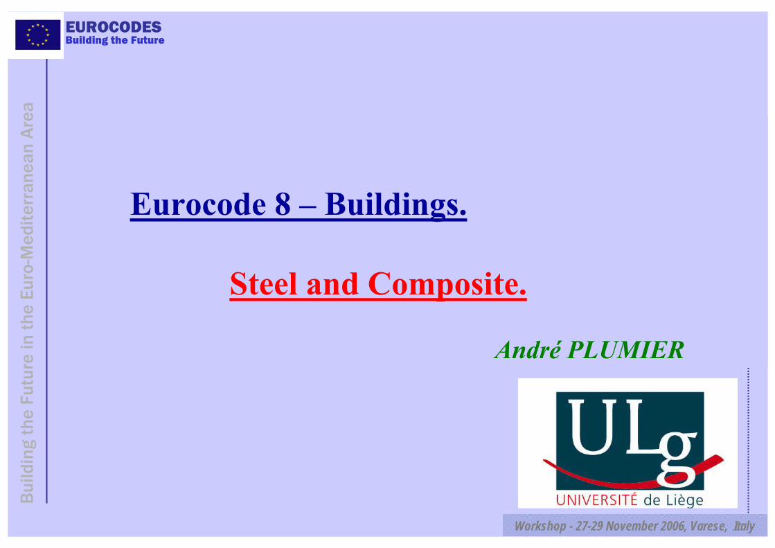
Foreword…
Origin of Eurocode 8 ruleson steel and composite steel – concrete structures
1986. ECCS Design RecommandationsECCS: European Convention for Constructional SteelworkAuthors: Aribert, Ballio, Mazzolani, Plumier, Sedlacek
1994. 1st Eurocode 8 = ENV For steel structures ≈ ECCS RecommendationsFor composite: really weak.
1994 – 2000 Research: ICONS ProjectECOEST, ECOLEADER

EUROCODES
Workshop - 27-29 November 2006, Varese, Italy
Bui
ldin
g th
e Fu
ture
in t
he E
uro-
Med
iterr
anea
n A
rea
Building the Future
ICONS Reports
<= Topic 4
= Background document to Eurocode 8 on composite steel concrete structures.
The world most developed code for those structures

EUROCODES
Workshop - 27-29 November 2006, Varese, Italy
Bui
ldin
g th
e Fu
ture
in t
he E
uro-
Med
iterr
anea
n A
rea
Building the Future
Eurocode 8. Section 6. Steel Buildings
6.1 General
Design Concepts q Ductility classesNon Dissipative Structures 1≤ q≤ 1,5 DCL L for Low Dissipative Structures 1,5<q< 4 DCM M for Medium Dissipative structures q ≥ 4 DCH H for HighDuctility classes:plastic deformation capacity without degradation of resistance
Design of non dissipative structures. (Eurocode 3)- requirements on steel material + bolts 8.8 -10.9- preferably in low seismicity regions- K bracings may not be used
EUROCODES
Workshop - 27-29 November 2006, Varese, Italy
Bui
ldin
g th
e Fu
ture
in t
he E
uro-
Med
iterr
anea
n A
rea
Building the Future
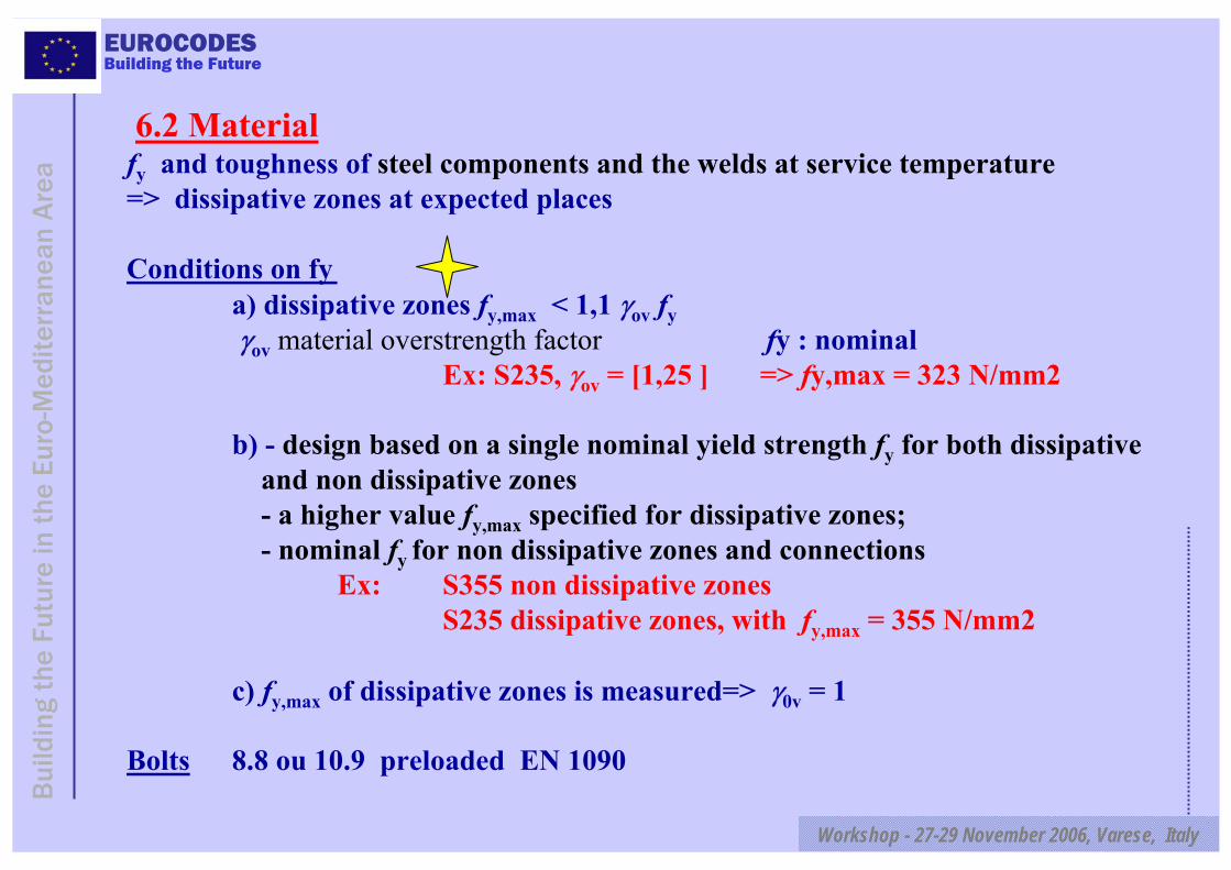
6.2 Materialfy and toughness of steel components and the welds at service temperature=> dissipative zones at expected places
Conditions on fya) dissipative zones fy,max < 1,1 γov fyγov material overstrength factor fy : nominal
Ex: S235, γov = [1,25 ] => fy,max = 323 N/mm2
b) - design based on a single nominal yield strength fy for both dissipative and non dissipative zones- a higher value fy,max specified for dissipative zones; - nominal fy for non dissipative zones and connections
Ex: S355 non dissipative zones S235 dissipative zones, with fy,max = 355 N/mm2
c) fy,max of dissipative zones is measured=> γ0v = 1
Bolts 8.8 ou 10.9 preloaded EN 1090
EUROCODES
Workshop - 27-29 November 2006, Varese, Italy
Bui
ldin
g th
e Fu
ture
in t
he E
uro-
Med
iterr
anea
n A
rea
Building the Future
6.12 Control of design and construction
Drawings indicate details, steel grades…noting the maximum permissible yield stress fymax of the steelto be used in the dissipative zones
Tightening of bolts to EN 1090
No structural changes involving a variation in stiffness orstrength of more than 10 % of the values assumed in design
If not, appropriate corrections or justifications
EUROCODES
Workshop - 27-29 November 2006, Varese, Italy
Bui
ldin
g th
e Fu
ture
in t
he E
uro-
Med
iterr
anea
n A
rea
Building the Future
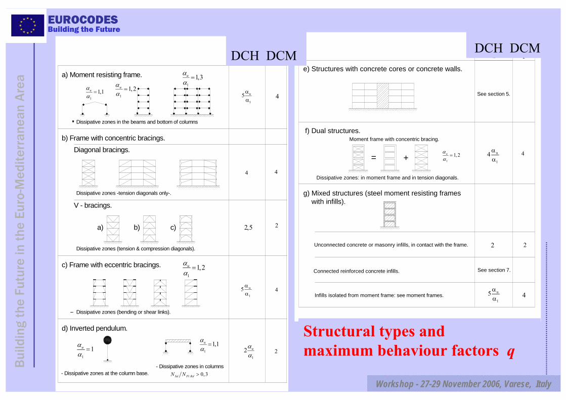
a) Moment resisting frame.
b) Frame with concentric bracings.
c) Frame with eccentric bracings.
d) Inverted pendulum.
Diagonal bracings.
V - bracings.
Dissipative zones in the beams and bottom of columns
Dissipative zones -tension diagonals only-.
u
1
5 αα
4
u
1
5 αα
a) b) c)
4
2
4
4
21
2 uαα
S I
Ductility Class
1
1,3=uαα
1
1,2=uαα
1
1,1=uαα
2,5
1
1,2=uαα
Dissipative zones (tension & compression diagonals).
1
1,1=uαα
Dissipative zones (bending or shear links).
- Dissipative zones at the column base.
1
1uαα
=
. 0,3>Sd Pl RdN N- Dissipative zones in columns
e) Structures with concrete cores or concrete walls.
See section 5.
f) Dual structures.
= +
Dissipative zones: in moment frame and in tension diagonals.
g) Mixed structures (steel moment resisting frames with infills).
Unconnected concrete or masonry infills, in contact with the frame.
Connected reinforced concrete infills.
u
1
5 αα
2
See section 7.
Moment frame with concentric bracing.
Ductility Class
S I
4
4
2
u
1
4 αα1
1, 2=uαα
Infills isolated from moment frame: see moment frames.
Structural types and maximum behaviour factors q
DCH DCM DCH DCM
EUROCODES
Workshop - 27-29 November 2006, Varese, Italy
Bui
ldin
g th
e Fu
ture
in t
he E
uro-
Med
iterr
anea
n A
rea
Building the Future
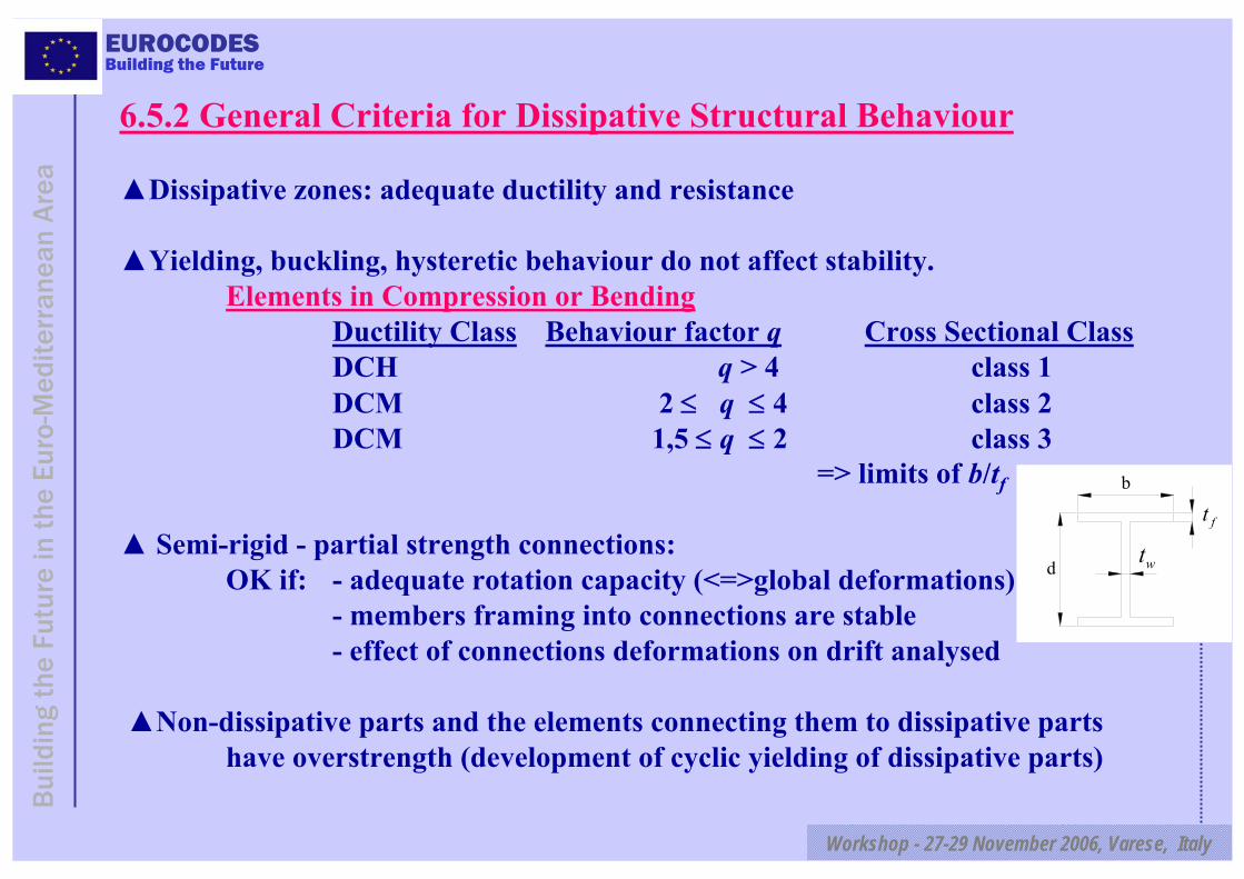
6.5.2 General Criteria for Dissipative Structural Behaviour
Dissipative zones: adequate ductility and resistance
Yielding, buckling, hysteretic behaviour do not affect stability.Elements in Compression or Bending
Ductility Class Behaviour factor q Cross Sectional ClassDCH q > 4 class 1DCM 2 ≤ q ≤ 4 class 2DCM 1,5 ≤ q ≤ 2 class 3
=> limits of b/tf
Semi-rigid - partial strength connections: OK if: - adequate rotation capacity (<=>global deformations)
- members framing into connections are stable- effect of connections deformations on drift analysed
Non-dissipative parts and the elements connecting them to dissipative parts have overstrength (development of cyclic yielding of dissipative parts)
ft
wt
b
d
EUROCODES
Workshop - 27-29 November 2006, Varese, Italy
Bui
ldin
g th
e Fu
ture
in t
he E
uro-
Med
iterr
anea
n A
rea
Building the Future
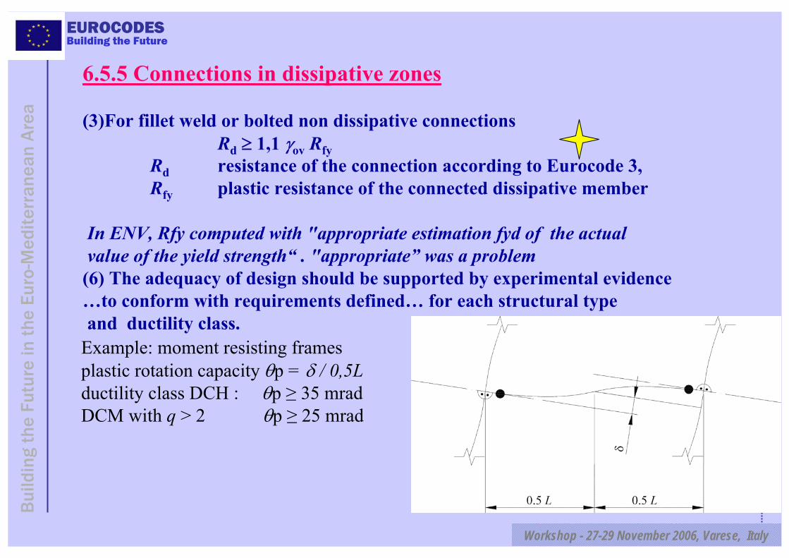
6.5.5 Connections in dissipative zones
(3)For fillet weld or bolted non dissipative connectionsRd ≥ 1,1 γov Rfy
Rd resistance of the connection according to Eurocode 3,Rfy plastic resistance of the connected dissipative member
In ENV, Rfy computed with "appropriate estimation fyd of the actual value of the yield strength“ . "appropriate” was a problem(6) The adequacy of design should be supported by experimental evidence…to conform with requirements defined… for each structural typeand ductility class.
Example: moment resisting framesplastic rotation capacity θp = δ / 0,5Lductility class DCH : θp ≥ 35 mradDCM with q > 2 θp ≥ 25 mrad
EUROCODES
Workshop - 27-29 November 2006, Varese, Italy
Bui
ldin
g th
e Fu
ture
in t
he E
uro-
Med
iterr
anea
n A
rea
Building the Future
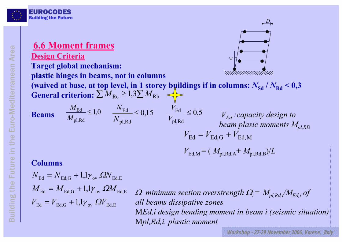
6.6 Moment framesDesign CriteriaTarget global mechanism: plastic hinges in beams, not in columns (waived at base, at top level, in 1 storey buildings if in columns: NSd / NRd < 0,3General criterion:
Beams VEd :capacity design to beam plasic moments Mpl,RD
Columns
Ω minimum section overstrength Ωi = Mpl,Rd,i/MEd,i of all beams dissipative zones MEd,i design bending moment in beam i (seismic situation) Mpl,Rd,i. plastic moment
ψ
D
∑ ∑≥ RbRc 3,1 MM
0,1Rdpl,
Ed ≤MM
15,0Rdpl,
Ed ≤NN 5,0
Rdpl,
Ed ≤VV
MEd,GEd,Ed VVV +=
VEd,M = ( Mpl,Rd,A+ Mpl,Rd,B)/L
EEd,ovGEd,Ed
EEd,ovGEd,Ed
EEd,ovGEd,Ed
1,11,1
1,1
VVVMMM
NNN
ΩγΩγ
Ωγ
+=
+=
+=
EUROCODES
Workshop - 27-29 November 2006, Varese, Italy
Bui
ldin
g th
e Fu
ture
in t
he E
uro-
Med
iterr
anea
n A
rea
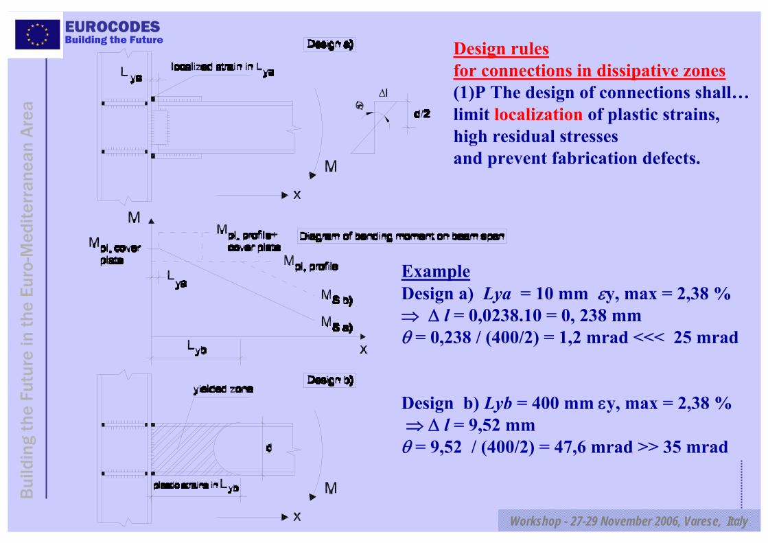
Building the Future Design rules for connections in dissipative zones(1)P The design of connections shall…limit localization of plastic strains, high residual stresses and prevent fabrication defects.
ExampleDesign a) Lya = 10 mm εy, max = 2,38 % ⇒ Δ l = 0,0238.10 = 0, 238 mmθ = 0,238 / (400/2) = 1,2 mrad <<< 25 mrad
Design b) Lyb = 400 mm εy, max = 2,38 % ⇒ Δ l = 9,52 mmθ = 9,52 / (400/2) = 47,6 mrad >> 35 mrad

EUROCODES
Workshop - 27-29 November 2006, Varese, Italy
Bui
ldin
g th
e Fu
ture
in t
he E
uro-
Med
iterr
anea
n A
rea
Building the Future
wp,Ed
wp,Rd
1,0VV
≤
Connection design detail Ductility classes: National Annexes
Shear resistance of framed web panels
Vwp,Ed < Vwb,Rd Vwb,Rd shear buckling resistance of the web panel
Vwp,Rd shear resistance of the web panel
EUROCODES
Workshop - 27-29 November 2006, Varese, Italy
Bui
ldin
g th
e Fu
ture
in t
he E
uro-
Med
iterr
anea
n A
rea
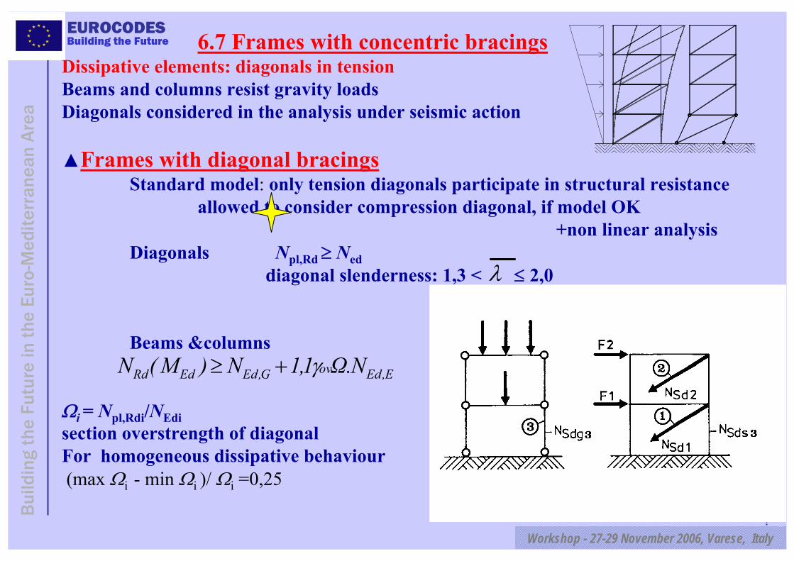
Building the Future 6.7 Frames with concentric bracingsDissipative elements: diagonals in tension Beams and columns resist gravity loads Diagonals considered in the analysis under seismic action
Frames with diagonal bracingsStandard model: only tension diagonals participate in structural resistance
allowed to consider compression diagonal, if model OK+non linear analysis
Diagonals Npl,Rd ≥ Neddiagonal slenderness: 1,3 < ≤ 2,0
Beams &columns
Ωi = Npl,Rdi/NEdisection overstrength of diagonalFor homogeneous dissipative behaviour (max Ωi - min Ωi )/ Ωi =0,25
λ
E,EdovG,EdEdRd N.Ω1,1N)M(N γ+≥

EUROCODES
Workshop - 27-29 November 2006, Varese, Italy
Bui
ldin
g th
e Fu
ture
in t
he E
uro-
Med
iterr
anea
n A
rea
Building the Future
Frames with V or Λ bracingsDissipative elements: diagonals in tension
Standard model: only beams and columns are in the model for gravity loadsCompression and tension diagonals participate in structural resistance to seismic action+ and - diagonals considered in standard analysis Diagonals Npl,Rd ≥ NEd Npl,Rd design bukling resistance
≤ 2,0Beams and columnsCapacity design to diagonals Ω minimum value of Ωi = Npl,Rd,i/NEd,i
Beams resist all non-seismic actions without considering the intermediate support given by the diagonals+ the unbalanced vertical seismic action effect applied to the beam by the braces after buckling of the compression diagonal. This force is calculated using:Npl,Rd for the brace in tension γpb Npl,Rd for the brace in compressionγpb = 0,3
λEEd,ovGEd,EdRdpl, .1,1)( NNMN Ωγ+≥
F1
N pl,Rd 0,3 N pl,Rd
EUROCODES
Workshop - 27-29 November 2006, Varese, Italy
Bui
ldin
g th
e Fu
ture
in t
he E
uro-
Med
iterr
anea
n A
rea
Building the Future
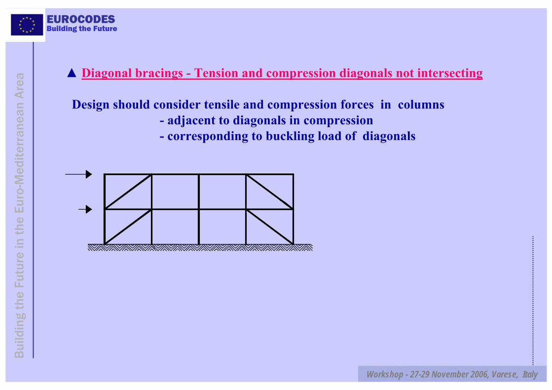
Diagonal bracings - Tension and compression diagonals not intersecting
Design should consider tensile and compression forces in columns - adjacent to diagonals in compression - corresponding to buckling load of diagonals
EUROCODES
Workshop - 27-29 November 2006, Varese, Italy
Bui
ldin
g th
e Fu
ture
in t
he E
uro-
Med
iterr
anea
n A
rea
Building the Future
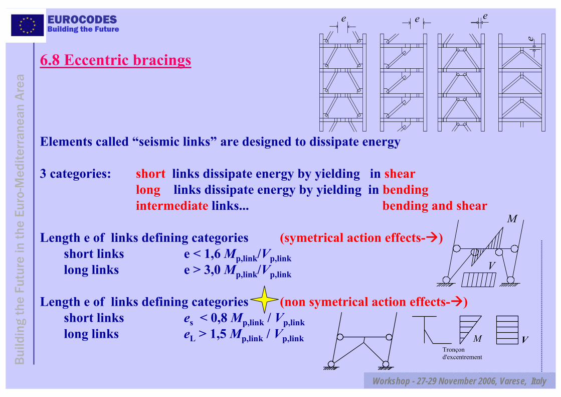
6.8 Eccentric bracings
Elements called “seismic links” are designed to dissipate energy
3 categories: short links dissipate energy by yielding in shearlong links dissipate energy by yielding in bendingintermediate links... bending and shear
Length e of links defining categories (symetrical action effects- )short links e < 1,6 Mp,link/Vp,linklong links e > 3,0 Mp,link/Vp,link
Length e of links defining categories (non symetrical action effects- )short links es < 0,8 Mp,link / Vp,linklong links eL > 1,5 Mp,link / Vp,link
e e e
e
M
V
M VTronçon d'excentrement

EUROCODES
Workshop - 27-29 November 2006, Varese, Italy
Bui
ldin
g th
e Fu
ture
in t
he E
uro-
Med
iterr
anea
n A
rea
Building the Future
Stiffeners in links.
Short links (shear on complete length)
Long links (plastic hinges at both ends)
E,EdovG,EdEdEdRd ΩN1,1N)V,M(N γ+≥
Members not containing seismic links:Capacity design to the links. Checks: like for concentric bracings
Ωi = 1,5 Mp,link,i/MEdi Ωi = 1,5 Vp,link,i /VEdi
EUROCODES
Workshop - 27-29 November 2006, Varese, Italy
Bui
ldin
g th
e Fu
ture
in t
he E
uro-
Med
iterr
anea
n A
rea
Building the Future
6.9 Inverted pendulum structure
≤ 1,5θ ≤ 0,20
6.10 Structures with concrete cores or concrete wallsConcrete structure is primary structure
Dual structuresMoment resisting frames and braced frames acting in the same direction: designed using a single q factor. Horizontal forces: distributed between frames according to their elastic stiffness
Mixed structuresReinforced concrete infills positively connected to steel structure=> compositeMoment resisting frame with infills structurally disconnected from frame on lateral and top sides: design as steel structures.Infills in contact: frame-infill interaction to take into account.
λ
EUROCODES
Workshop - 27-29 November 2006, Varese, Italy
Bui
ldin
g th
e Fu
ture
in t
he E
uro-
Med
iterr
anea
n A
rea
Building the Future
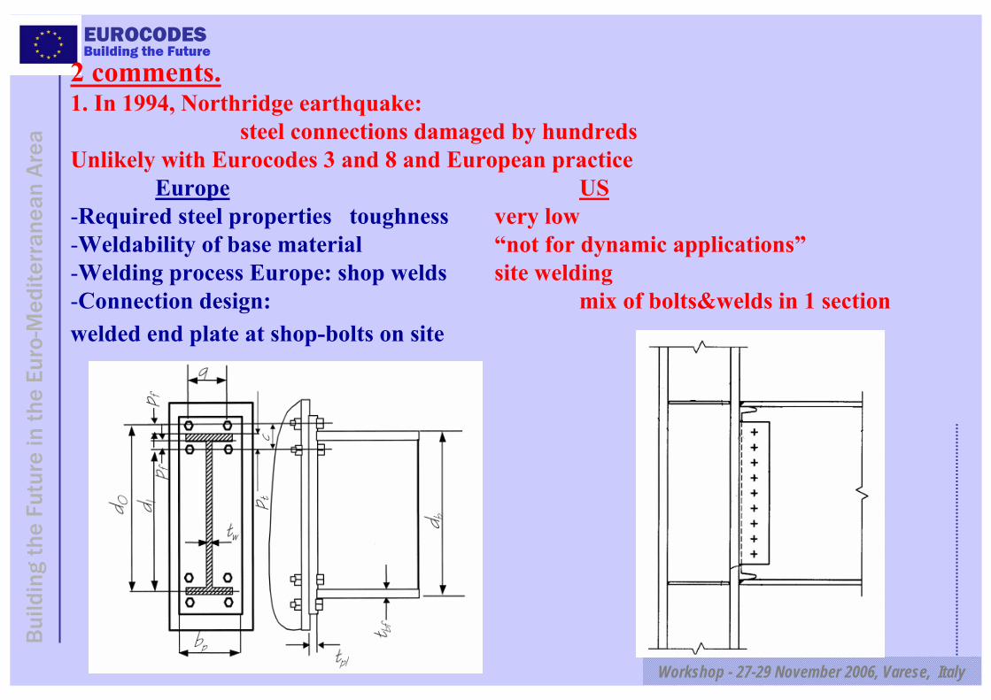
2 comments.1. In 1994, Northridge earthquake:
steel connections damaged by hundredsUnlikely with Eurocodes 3 and 8 and European practice
Europe US-Required steel properties toughness very low-Weldability of base material “not for dynamic applications”-Welding process Europe: shop welds site welding-Connection design: mix of bolts&welds in 1 sectionwelded end plate at shop-bolts on site
EUROCODES
Workshop - 27-29 November 2006, Varese, Italy
Bui
ldin
g th
e Fu
ture
in t
he E
uro-
Med
iterr
anea
n A
rea
Building the Future
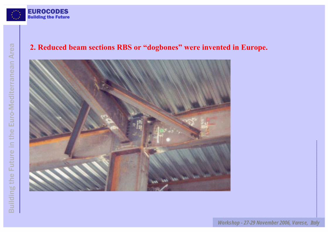
2. Reduced beam sections RBS or “dogbones” were invented in Europe.
EUROCODES
Workshop - 27-29 November 2006, Varese, Italy
Bui
ldin
g th
e Fu
ture
in t
he E
uro-
Med
iterr
anea
n A
rea
Building the Future
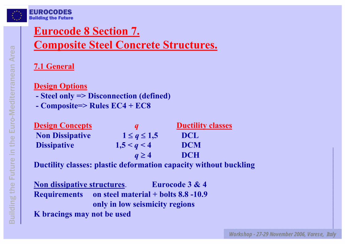
Eurocode 8 Section 7. Composite Steel Concrete Structures.
7.1 General
Design Options- Steel only => Disconnection (defined)- Composite=> Rules EC4 + EC8
Design Concepts q Ductility classesNon Dissipative 1 ≤ q ≤ 1,5 DCL Dissipative 1,5 < q < 4 DCM
q ≥ 4 DCHDuctility classes: plastic deformation capacity without buckling
Non dissipative structures. Eurocode 3 & 4Requirements on steel material + bolts 8.8 -10.9
only in low seismicity regionsK bracings may not be used
EUROCODES
Workshop - 27-29 November 2006, Varese, Italy
Bui
ldin
g th
e Fu
ture
in t
he E
uro-
Med
iterr
anea
n A
rea
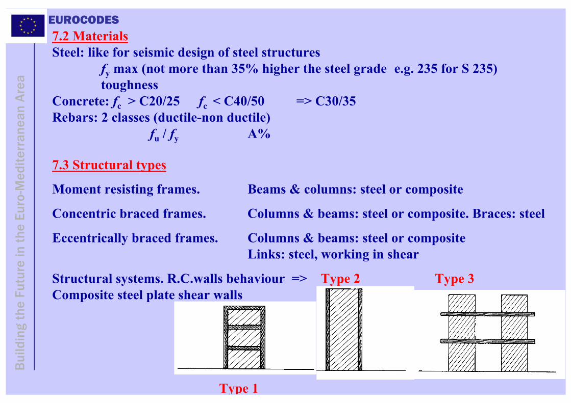
Building the Future7.2 MaterialsSteel: like for seismic design of steel structures
fy max (not more than 35% higher the steel grade e.g. 235 for S 235) toughness
Concrete: fc > C20/25 fc < C40/50 => C30/35Rebars: 2 classes (ductile-non ductile)
fu / fy A%
7.3 Structural types
Moment resisting frames. Beams & columns: steel or composite
Concentric braced frames. Columns & beams: steel or composite. Braces: steel
Eccentrically braced frames. Columns & beams: steel or composite Links: steel, working in shear
Structural systems. R.C.walls behaviour => Type 2 Type 3Composite steel plate shear walls
Type 1
EUROCODES
Workshop - 27-29 November 2006, Varese, Italy
Bui
ldin
g th
e Fu
ture
in t
he E
uro-
Med
iterr
anea
n A
rea
Building the Future
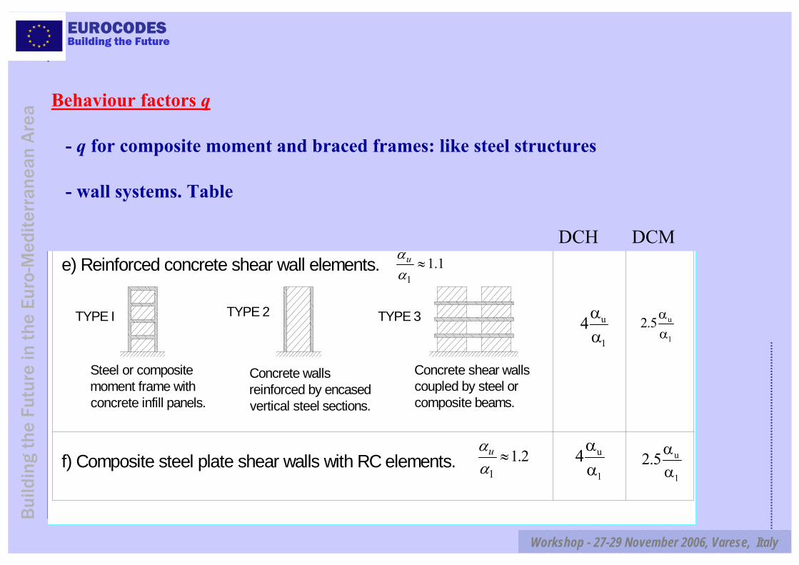
e) Reinforced concrete shear wall elements.
Steel or composite moment frame with concrete infill panels.
Concrete shear walls coupled by steel or composite beams.
Concrete walls reinforced by encased vertical steel sections.
1.11
≈ααu
TYPE I TYPE 2 TYPE 3
Ductility Class
S I
f) Composite steel plate shear walls with RC elements. 2.11
≈ααu u
1
2.5 αα
u
1
4αα
u
1
4αα
u
1
2.5 αα
Behaviour factors q
- q for composite moment and braced frames: like steel structures
- wall systems. Table
DCH DCM
EUROCODES
Workshop - 27-29 November 2006, Varese, Italy
Bui
ldin
g th
e Fu
ture
in t
he E
uro-
Med
iterr
anea
n A
rea
Building the Future
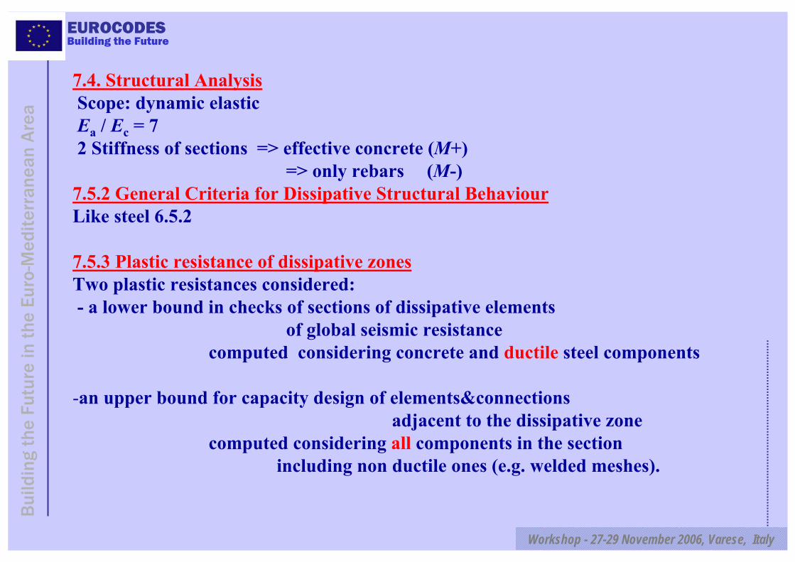
7.4. Structural AnalysisScope: dynamic elasticEa / Ec = 72 Stiffness of sections => effective concrete (M+)
=> only rebars (M-)7.5.2 General Criteria for Dissipative Structural BehaviourLike steel 6.5.2
7.5.3 Plastic resistance of dissipative zonesTwo plastic resistances considered:- a lower bound in checks of sections of dissipative elements
of global seismic resistance computed considering concrete and ductile steel components
-an upper bound for capacity design of elements&connectionsadjacent to the dissipative zone
computed considering all components in the sectionincluding non ductile ones (e.g. welded meshes).
EUROCODES
Workshop - 27-29 November 2006, Varese, Italy
Bui
ldin
g th
e Fu
ture
in t
he E
uro-
Med
iterr
anea
n A
rea
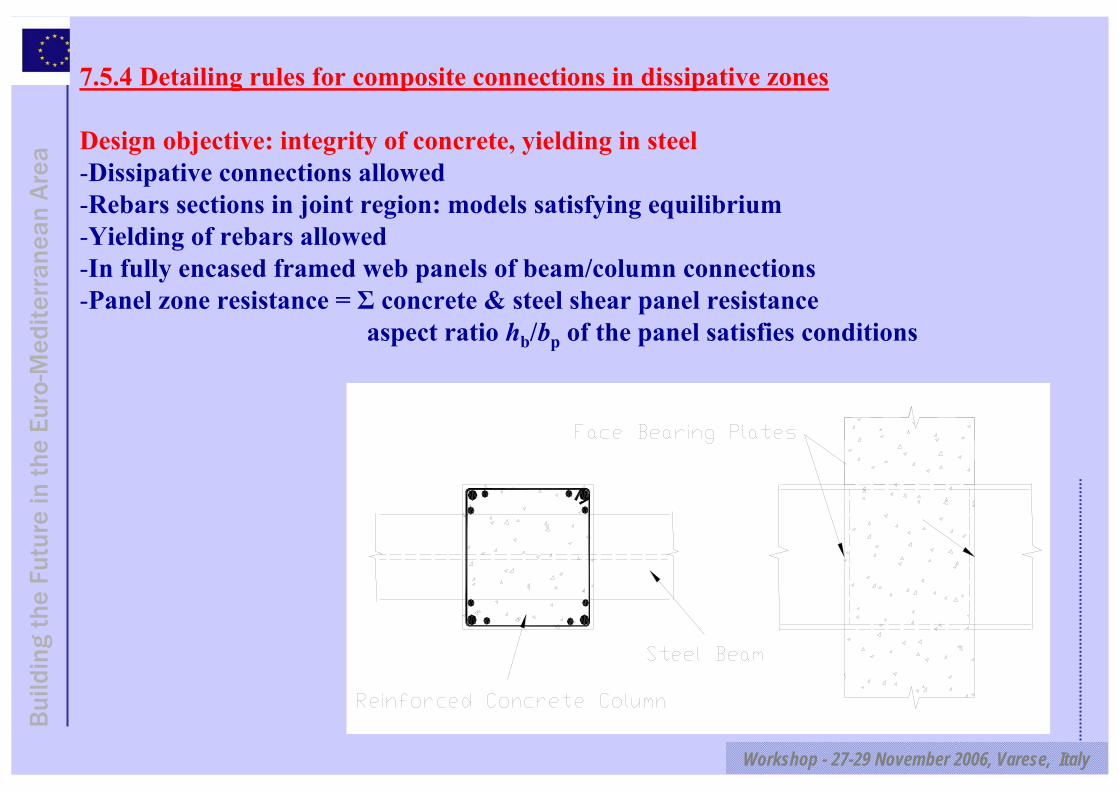
Building the Future7.5.4 Detailing rules for composite connections in dissipative zones
Design objective: integrity of concrete, yielding in steel -Dissipative connections allowed-Rebars sections in joint region: models satisfying equilibrium-Yielding of rebars allowed-In fully encased framed web panels of beam/column connections-Panel zone resistance = Σ concrete & steel shear panel resistance
aspect ratio hb/bp of the panel satisfies conditions

EUROCODES
Workshop - 27-29 November 2006, Varese, Italy
Bui
ldin
g th
e Fu
ture
in t
he E
uro-
Med
iterr
anea
n A
rea
Building the Future
Vertical rebars to take beam shear forceIf composite column, distribute beam shear between steel and concrete
In partially encased stiffened web panels: similar Σ, additional conditions
h b
b c
b b
t
b p = h c
EUROCODES
Workshop - 27-29 November 2006, Varese, Italy
Bui
ldin
g th
e Fu
ture
in t
he E
uro-
Med
iterr
anea
n A
rea
Building the Future
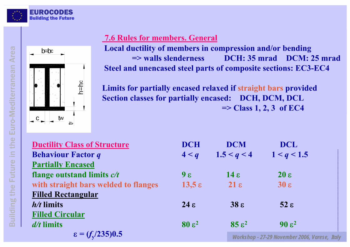
7.6 Rules for members. GeneralLocal ductility of members in compression and/or bending
=> walls slenderness DCH: 35 mrad DCM: 25 mradSteel and unencased steel parts of composite sections: EC3-EC4
Limits for partially encased relaxed if straight bars providedSection classes for partially encased: DCH, DCM, DCL
=> Class 1, 2, 3 of EC4
Ductility Class of Structure DCH DCM DCLBehaviour Factor q 4 < q 1.5 < q < 4 1 < q < 1.5Partially Encasedflange outstand limits c/t 9 ε 14 ε 20 εwith straight bars welded to flanges 13,5 ε 21 ε 30 εFilled Rectangularh/t limits 24 ε 38 ε 52 εFilled Circulard/t limits 80 ε2 85 ε2 90 ε2
ε = (fy/235)0.5
b=bc
tfh=
hc
twc
EUROCODES
Workshop - 27-29 November 2006, Varese, Italy
Bui
ldin
g th
e Fu
ture
in t
he E
uro-
Med
iterr
anea
n A
rea
Building the Future
Columns Columns generally not dissipative => EC 4 designColumns may be dissipative : - at ground level in moment frames
- top&bottom of fully encased columns at any storey(= "critical zones" of RC)
Bond and friction shear resistance not reliable in cyclic conditionsIn non-dissipative columns design bond stress = 1/3 static If bond stress insufficient => shear connectors
For all columns, in bending, steel alone or combined resistances of steel and concrete may be considered
For shear resistance: strong restrictions (research needed)fully encased => concrete section resistancepartially encased => steel section resistancefilled => either steel or concrete considered resistance

EUROCODES
Workshop - 27-29 November 2006, Varese, Italy
Bui
ldin
g th
e Fu
ture
in t
he E
uro-
Med
iterr
anea
n A
rea
Building the Future
Steel beams with slabDesign objective: - maintain integrity of slab
- yielding in steel section and/or rebarsDuctility in plastic hingesP.N.A= Plastic Neutral Axisεcu = concrete crushing strainεapl = plastic strain of steel
εapl
x
d
εcu
P.N.A.
/ ε≤
ε +εcu
cu aplx d
εcu= 2,5 10-3 εs= q εy = q fy / E=>x/d upper limits Ductility class q fy x/d upper limit
DCH q ≥ 4 355 0,19DCH q ≥ 4 235 0,26DCM 1,5 < q < 4 355 0,26DCM 1,5 < q < 4 235 0,35

EUROCODES
Workshop - 27-29 November 2006, Varese, Italy
Bui
ldin
g th
e Fu
ture
in t
he E
uro-
Med
iterr
anea
n A
rea
Building the Future
Steel beams with slab- Partial shear connection in dissipative zones of beams OK if
# in M>0 region, connection degree > 0,8 # total resistance of connectors in M<0 region > plastic resistance of rebars.
-Reduction of shear resistance by a rib shape efficiency factor kr if steel sheeting with ribs transverse to beams
kr = 1 kr = 1 kr = 0,8-Full shear connection required with non ductile connectors

EUROCODES
Workshop - 27-29 November 2006, Varese, Italy
Bui
ldin
g th
e Fu
ture
in t
he E
uro-
Med
iterr
anea
n A
rea
Building the Future
Definition of longitudinal & transverse elements + details in Moment Frame Structure
EUROCODES
Workshop - 27-29 November 2006, Varese, Italy
Bui
ldin
g th
e Fu
ture
in t
he E
uro-
Med
iterr
anea
n A
rea
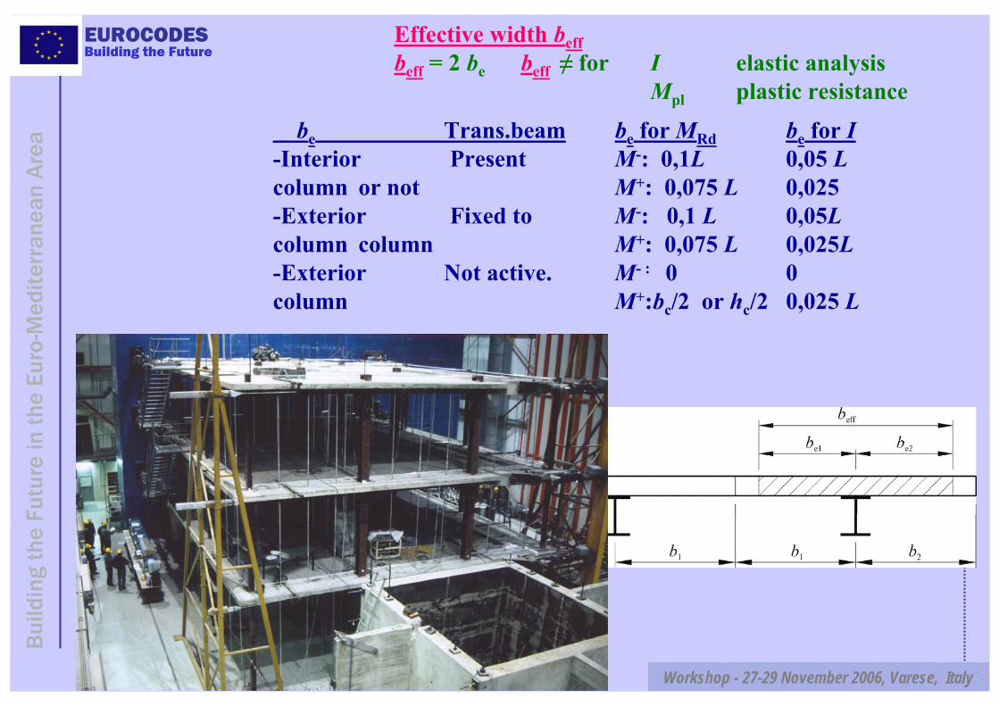
Building the FutureEffective width beffbeff = 2 be beff ≠ for I elastic analysis
Mpl plastic resistance
be Trans.beam be for MRd be for I-Interior Present M-: 0,1L 0,05 Lcolumn or not M+: 0,075 L 0,025 -Exterior Fixed to M-: 0,1 L 0,05Lcolumn column M+: 0,075 L 0,025L-Exterior Not active. M- : 0 0column M+:bc/2 or hc/2 0,025 L
EUROCODES
Workshop - 27-29 November 2006, Varese, Italy
Bui
ldin
g th
e Fu
ture
in t
he E
uro-
Med
iterr
anea
n A
rea
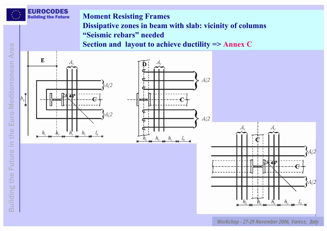
Building the Future Moment Resisting Frames Dissipative zones in beam with slab: vicinity of columns“Seismic rebars” neededSection and layout to achieve ductility => Annex C
EUROCODES
Workshop - 27-29 November 2006, Varese, Italy
Bui
ldin
g th
e Fu
ture
in t
he E
uro-
Med
iterr
anea
n A
rea
Building the Future
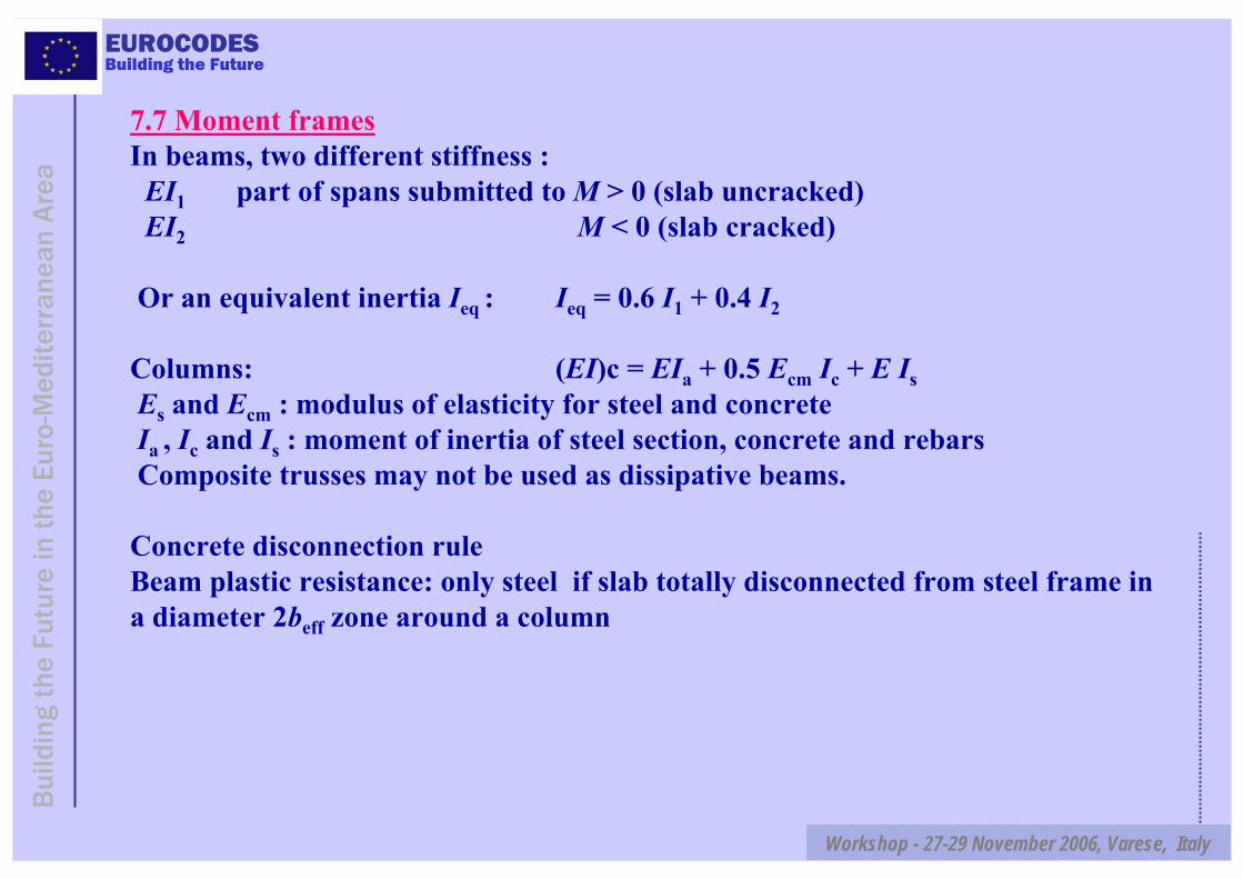
7.7 Moment framesIn beams, two different stiffness :
EI1 part of spans submitted to M > 0 (slab uncracked) EI2 M < 0 (slab cracked)
Or an equivalent inertia Ieq : Ieq = 0.6 I1 + 0.4 I2
Columns: (EI)c = EIa + 0.5 Ecm Ic + E IsEs and Ecm : modulus of elasticity for steel and concreteIa , Ic and Is : moment of inertia of steel section, concrete and rebarsComposite trusses may not be used as dissipative beams.
Concrete disconnection ruleBeam plastic resistance: only steel if slab totally disconnected from steel frame in a diameter 2beff zone around a column
EUROCODES
Workshop - 27-29 November 2006, Varese, Italy
Bui
ldin
g th
e Fu
ture
in t
he E
uro-
Med
iterr
anea
n A
rea
Building the Future
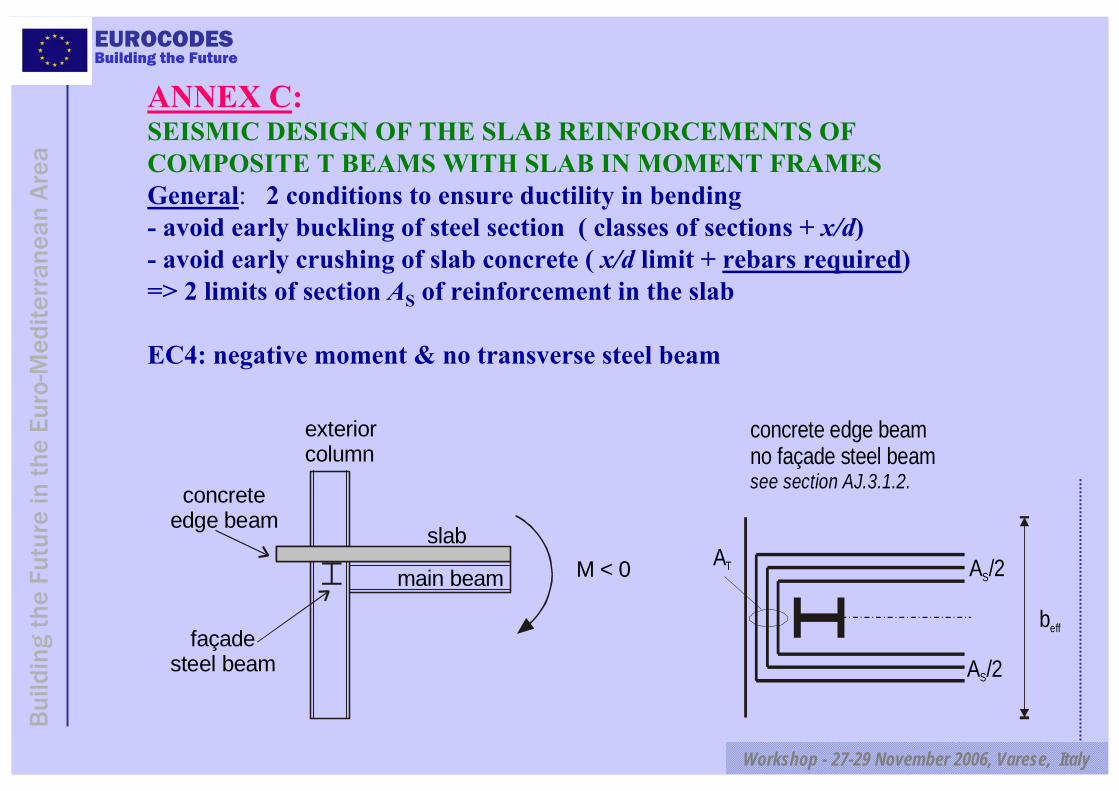
ANNEX C:SEISMIC DESIGN OF THE SLAB REINFORCEMENTS OF COMPOSITE T BEAMS WITH SLAB IN MOMENT FRAMESGeneral: 2 conditions to ensure ductility in bending - avoid early buckling of steel section ( classes of sections + x/d)- avoid early crushing of slab concrete ( x/d limit + rebars required)=> 2 limits of section AS of reinforcement in the slab
EC4: negative moment & no transverse steel beam
M < 0
concreteedge beam
façadesteel beam
exteriorcolumn
slab
main beam
concrete edge beamno façade steel beamsee section AJ.3.1.2.
beff
A /2S
A /2S
AT
EUROCODES
Workshop - 27-29 November 2006, Varese, Italy
Bui
ldin
g th
e Fu
ture
in t
he E
uro-
Med
iterr
anea
n A
rea
Building the Future
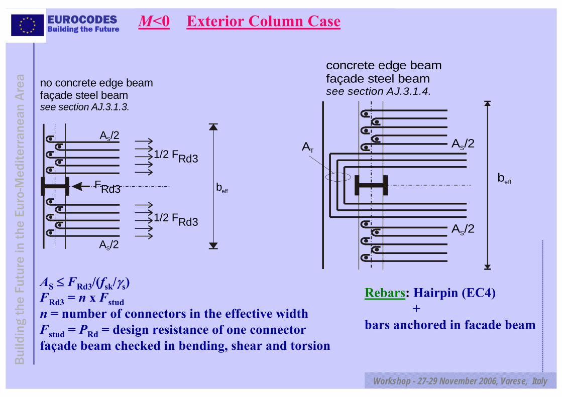
no concrete edge beamfaçade steel beamsee section AJ.3.1.3.
beff
A /2S
A /2S
FRd3
1/2 FRd3
1/2 FRd3
AS ≤ FRd3/(fsk/γs)FRd3 = n x Fstudn = number of connectors in the effective widthFstud = PRd = design resistance of one connectorfaçade beam checked in bending, shear and torsion
M<0 Exterior Column Case
concrete edge beamfaçade steel beamsee section AJ.3.1.4.
beff
ATA /2S
A /2S
Rebars: Hairpin (EC4) +
bars anchored in facade beam

EUROCODES
Workshop - 27-29 November 2006, Varese, Italy
Bui
ldin
g th
e Fu
ture
in t
he E
uro-
Med
iterr
anea
n A
rea
Building the Future
M > 0
concreteedge beam
façadesteel beam
exteriorcolumn
slab
main beam
Exterior Column Case3 Force Transfer Mechanisms
of Slab Compression
Mechanism 1Direct compression on columnFRd1 = bc deff (0.85 fck/γc)Confinement of concrete close to column flange by transverse re-bars
no concrete edge beamno façade steel beamsee section AJ.3.2.1.
FRd1 FRd1
hc
bc

EUROCODES
Workshop - 27-29 November 2006, Varese, Italy
Bui
ldin
g th
e Fu
ture
in t
he E
uro-
Med
iterr
anea
n A
rea
Building the FutureMechanism 2Compression on column sides by concrete struts
concrete edge beam or concrete into the column flangesno façade steel beamsee section AJ.3.2.2.
mechanism 2AT
1/2 FRd2
FRd2
1/2 FRd2
hc hc
θ = 45°
b+
4h+
2lc
cb
bc
FRd2 = 0.7 hc deff (0.85 fck/γc)
deff : depth of the slabR d 2 c k c
T c e ffsk ,T s sk ,T s
F f /A 0 .3 h df / f /
γ≥ =
γ γ
max compr. force : FRd1 + FRd2 = beff deff (0.85 fck/γc)b+
eff connec = 0.7 hc + bc ≅ 1.7 bc≅ 0.085 L << b+
eff = 0.15 L≅ 0.5 b+eff (EC4)

EUROCODES
Workshop - 27-29 November 2006, Varese, Italy
Bui
ldin
g th
e Fu
ture
in t
he E
uro-
Med
iterr
anea
n A
rea
Building the Future
Mechanism 3 Compression on connectors of facade steel beamFRd3 = n x Fstud n = number of connectors in effective width
Fstud = PRd = design resistance of one connector
concrete edge beam present or notfaçade steel beamsee section AJ.3.2.3.
beff
1/2 FRd3
1/2 FRd3
FRd3
maximum compression force beff deff (0.85 fck/γc)transmitted if:
FRd1 + FRd2 + FRd3 > beff deff (0.85 fck/γc)
=> choose n to achieve adequate FRd3
EUROCODES
Workshop - 27-29 November 2006, Varese, Italy
Bui
ldin
g th
e Fu
ture
in t
he E
uro-
Med
iterr
anea
n A
rea
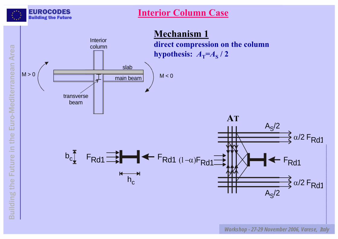
Building the FutureInterior Column Case
Interior column
transversebeam
M > 0 M < 0slab
main beam
FRd1FRd1bc
hc
A /2S
A /2S
FRd1(1−α)FRd1
α/2 FRd1
α/2 FRd1
Mechanism 1direct compression on the columnhypothesis: AT=AS / 2
AT
EUROCODES
Workshop - 27-29 November 2006, Varese, Italy
Bui
ldin
g th
e Fu
ture
in t
he E
uro-
Med
iterr
anea
n A
rea
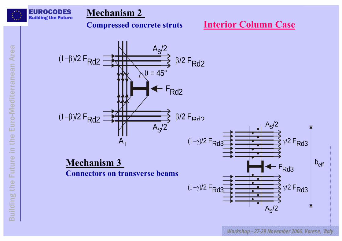
Building the FutureMechanism 2 Compressed concrete struts Interior Column Case
A /2S
AT
β/2 FRd2(1−β)/2 FRd2
FRd2
β/2 FRd2(1−β)/2 FRd2θ = 45°
A /2S
γ/2 FRd3(1−γ)/2 FRd3
FRd3
(1−γ)/2 FRd3 γ/2 FRd3
A /2S
A /2S
beffMechanism 3 Connectors on transverse beams

EUROCODES
Workshop - 27-29 November 2006, Varese, Italy
Bui
ldin
g th
e Fu
ture
in t
he E
uro-
Med
iterr
anea
n A
rea
Building the Future Interior Column Case
Without Transverse Beam: FRd1 = bc deff (0.85 fck/γc)FRd2 = 0.7 hc deff (0.85 fck/γc)same section AT on each side of column
Rd2 ck cT c eff
sk,T s sk,T s
F f /A 0.3h df / f /
γ≥ =
γ γ
Resistance: FRd1 + FRd2 = (0.7 hc + bc) deff (0.85 fck/γc)Applied force : tension of re-bars (M- side) + compression of concrete (M+ side)FSt + FSc = AS (fsk /γs) + b+
eff deff (0.85 fck/γc)
Impossible to transfer force corresponding to effective width under M > 0 & M < 0=>situation is not controlled = no ductility
With Transverse BeamFRd3 activated FRd3 = n x FstudResistance: FRd1 + FRd2 + FRd3 = (0.7 hc + bc) deff (0.85 fck/γc) + n FstudCheck 1.2 (FSc + FSt) ≤ FRd1 + FRd2 + FRd3
The situation is controlled and the transferred forces correspond to the EC8 effective widths b-eff = 0.2 L and b+eff = 0.15L

EUROCODES
Workshop - 27-29 November 2006, Varese, Italy
Bui
ldin
g th
e Fu
ture
in t
he E
uro-
Med
iterr
anea
n A
rea
Building the Future
7.8 Composite concentrically braced framesConcepts- Yielding of diagonals in tension- Tension only design & no composite braces
7.9 Composite eccentrically braced frames- Dissipative action occur through yielding in shear of links- All other members remain elastic- Links may be short or intermediate with a maximum length ee < 2Mp, link/ Vp, link
- Links are made of steel sections, possibly composite with slabs,not encased
- In a composite brace under tension, only the steel section isconsidered in the resistance of the brace - Failure of connections is prevented
EUROCODES
Workshop - 27-29 November 2006, Varese, Italy
Bui
ldin
g th
e Fu
ture
in t
he E
uro-
Med
iterr
anea
n A
rea
Building the Future
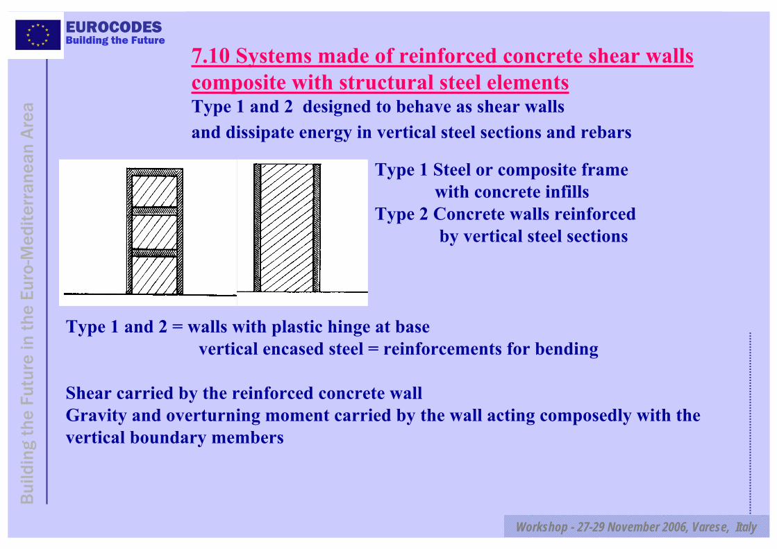
7.10 Systems made of reinforced concrete shear wallscomposite with structural steel elementsType 1 and 2 designed to behave as shear walls and dissipate energy in vertical steel sections and rebars
Type 1 Steel or composite frame with concrete infills
Type 2 Concrete walls reinforced by vertical steel sections
Type 1 and 2 = walls with plastic hinge at basevertical encased steel = reinforcements for bending
Shear carried by the reinforced concrete wallGravity and overturning moment carried by the wall acting composedly with the vertical boundary members
EUROCODES
Workshop - 27-29 November 2006, Varese, Italy
Bui
ldin
g th
e Fu
ture
in t
he E
uro-
Med
iterr
anea
n A
rea
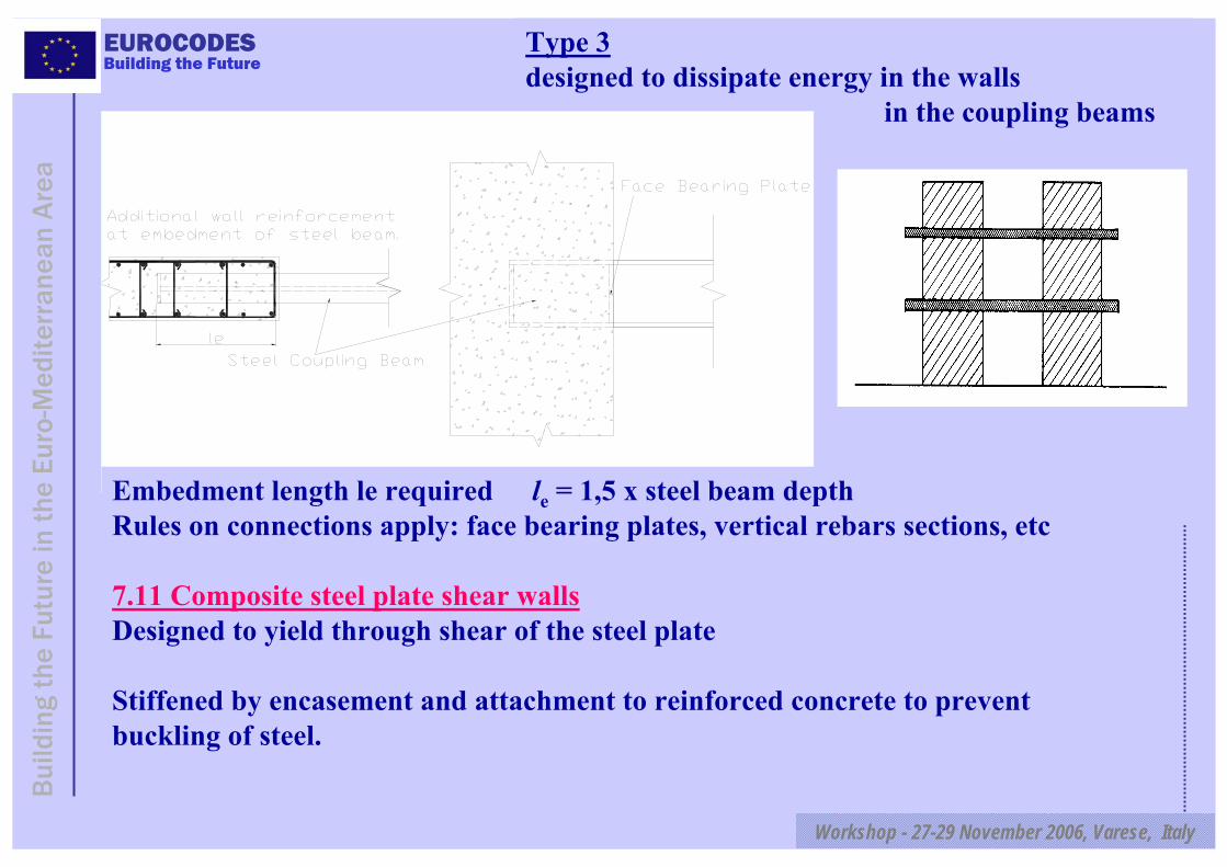
Building the FutureType 3designed to dissipate energy in the walls
in the coupling beams
Embedment length le required le = 1,5 x steel beam depthRules on connections apply: face bearing plates, vertical rebars sections, etc
7.11 Composite steel plate shear wallsDesigned to yield through shear of the steel plate
Stiffened by encasement and attachment to reinforced concrete to prevent buckling of steel.
EUROCODES
Workshop - 27-29 November 2006, Varese, Italy
Bui
ldin
g th
e Fu
ture
in t
he E
uro-
Med
iterr
anea
n A
rea
Building the FutureAnd finally… education is the key
2 personal involvments: - writing 1 book for students- Organising seminars in Algeria for a total of 15 daysOn seismic design of bridges, soils and foundations, buildings and retrofitting.
With the financial help of the European Investment BankWith the friendly contribution of a number ofspecialists.With constant reference to Eurocode 8
Thank you for your attention !