Embed Size (px)
Citation preview
Euro ET
www.highwayguardrail.com

Euro ET
Version 1.3 Page 2BUILDING TOMORROW`S HIGHWAY
SAFETY SOLUTIONS TODAY
Table of Content
About ET………………………………………………………………………………….3
Product Overview………………………………………………………………………..4
Full Scale Crash Tests………………………………………………………………….5
Typical Crash Sequence……………………………………………………………….6
Photos of Installation……………………………………………………………………7
Photos after Impact……………………………………………………………………..8
Installation Instructions……………………………………………………………….. 9
Installation Check List………………………………………………………………...19
Maintenance and Repair Instructions……………………………………………….20
Annex 1………………………………………………………………………….Drawings
Annex 2………………………………………………………..….In-Service Evaluation
Euro ET
Version 1.3 Page 3BUILDING TOMORROW`S HIGHWAY
SAFETY SOLUTIONS TODAY
About ET 2000TM and the Family of ET Products
First installed in 1990 as an NCHRP-230 product, ET-2000TM is the first extruder terminaldesigned to eliminate the hazard of guardrail ends. In 1995, ET-2000TM became the firstNCHRP Report 350, level 3, guardrail end treatment.Since initial introduction, over 100,000 ET-2000TM ´s have been installed throughout theUnited States and around the world. While improvements in the overall system have beenadopted, the same durable original Extruder Head continues to serve impeccably.Additional economies are obtained by re-using the head with repaired installations.Our current record for maximum re-uses of the same head is nineteen.
EURO ET
To meet the requirements from those who prefer steel posts Trinity has developed theEURO ET. This is a all steel version of the successful ET-2000TM including the newPlus Head. The EURO ET comes with two reuseable HBA posts (Euro. Pat. Appl. 1147261)and four C120 steel posts, which fits into all existing W-beam guardrail systems.
How EURO ET Saves Lives
Upon impact with the EURO ET, a vehicle forces the extruder “head” along the guardrail,bending the steel posts and flattening and curving the guardrail away from the traffic as itbrings the vehicle to a controlled stop. In the extruding process, the kinetic energy of theimpacting vehicle is absorbed by the force required to reduce the W-beam shape of theguardrail to a flatter section.
Where to Use EURO ET
When minimal right of way or limited shoulder exists, or if limited budgets do not coverthe cost of added earth work requirements for flared terminals, EURO ET is the lowestcost choice of NCHRP 350/prEN 1317-4 guardrail end treatments.
Why Specify EURO ET
EURO ET´s reuseable Extruder head means lower repair cost if hit, which allows reducedparts inventories. Other fine-tuned features make EURO ET easy to install and repair.Unique design, distinctive features and no flare requirements, along with years of provenperformance all make specifying EURO ET a wise policy. An In-service evaluation reportbased on field data confirms the superior performance of ET-family.
CE Certificate
EURO ET hold´s a CE Certificate 0402-CPD-49 58 03 in accordance to EN 1317-5.
Euro ET
Version 1.3 Page 4BUILDING TOMORROW`S HIGHWAY
SAFETY SOLUTIONS TODAY
Product Overview
Dimensions Class P4 (P2)
Length……………………………………………………………………………12,000 (4,000) mmWidth……………………………………………………………………………………….....381 mmPost Spacing……………………………………………………………………………….2,000 mm
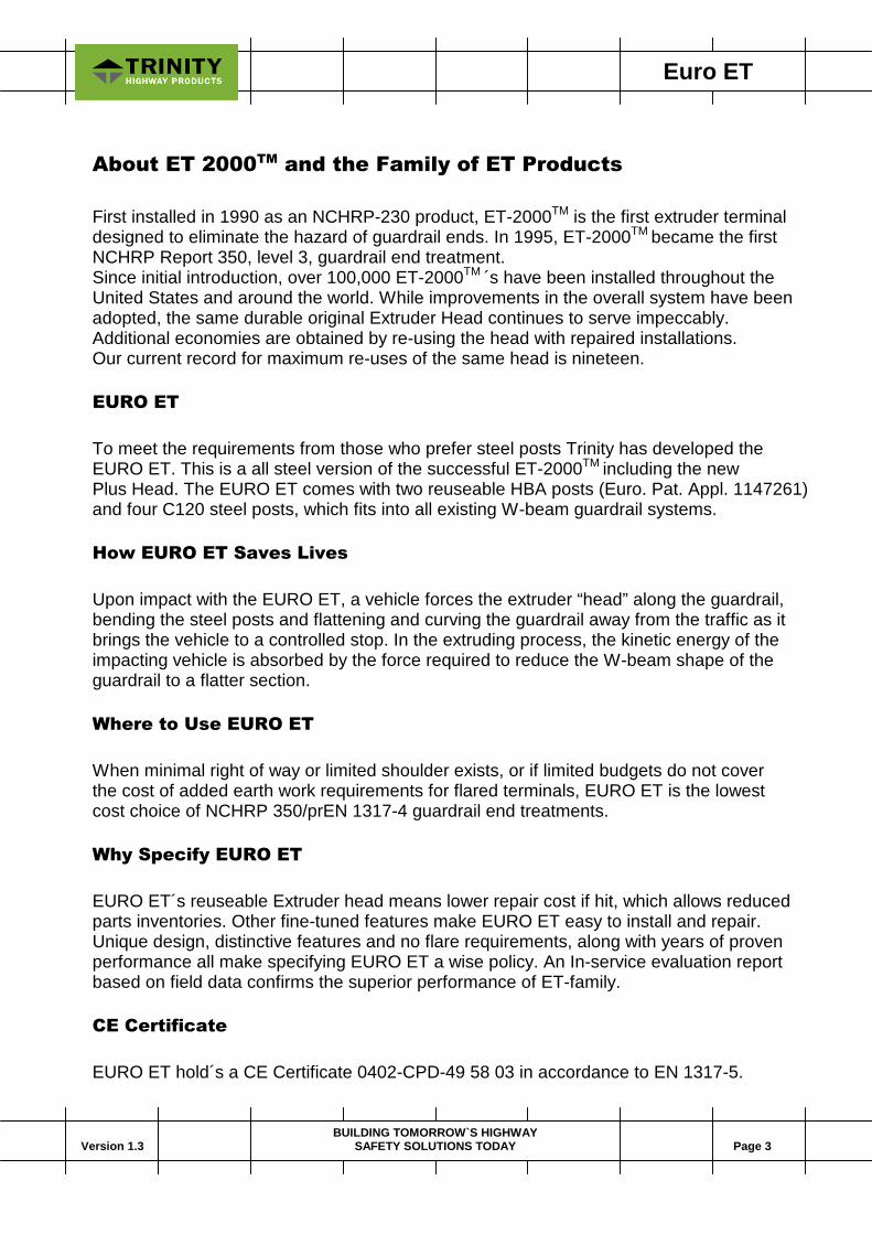
Energy Absorbing Technic
Upon impact with the EURO ET, a vehicle forces the extruder head along the guardrail,bending the steel posts and flattening and curving the guardrail away from the traffic as itbrings the vehicle to a controlled stop. In the extruding process, the kinetic energy of theimpacting vehicle is absorbed by the force required to reduce the W-beam shape of theguardrail to a flatter section.

Euro ET
Version 1.3 Page 5BUILDING TOMORROW`S HIGHWAY
SAFETY SOLUTIONS TODAY
Full Scale Crash Tests
The ET-family has been subject for a very comprehensive test program. It’s impossible toreport all figures and information in a document like this. Following is a short review of someof the test results. There are some differences in configuration of the tested systems due towhen the test was carried out and to which standard/level.
Standard Level Speed Mass Angle
NCHRP 350 3 102 km/h 2,028 kg 20.3 (side impact)
NCHRP 350 3 99 km/h 815 kg 14.8
NCHRP 350 3 102 km/h 1,990 kg 15
NCHRP 350 3 104 km/h 2,018 kg 0.8
NCHRP 350 3 101 km/h 2,000 kg 170 (reversed side impact)
PrEN 1317-4 4 114 km/h 1,427 kg 0
PrEN 1317-4 4 104 km/h 905 kg 0 (1/4 offset)
PrEN 1317-4 4 101 km/h 908 kg 165 (reversed side impact)
PrEN 1317-4 4 112 km/h 1,428 kg 15 (side impact)
There have been tests carried out to NCHRP 230 and the system has also been approvedto NCHRP 350 Level 2.
In all above mentioned tests ET has passed by filling or exceeding the criteria. For moredetailed information regarding PHD, THIV and ASI please contact us. We can also submitboth videos and high-speed films from the tests if required.
ET-family can be designed for speeds from 70-120 km/h (Class P2-P4) and for vehicles from800-2,050 kg.
Class P2 Terminal (L=4.0 meter)
Euro ET
Version 1.3 Page 6BUILDING TOMORROW`S HIGHWAY
SAFETY SOLUTIONS TODAY
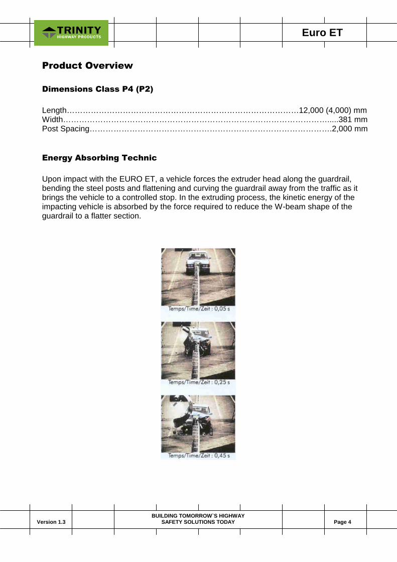
Typical Crash Sequence
Crash Test conducted at LIER in Lyon, France the 12th of October 2000.

Euro ET
Version 1.3 Page 7BUILDING TOMORROW`S HIGHWAY
SAFETY SOLUTIONS TODAY
Photos of Installation

Euro ET
Version 1.3 Page 8BUILDING TOMORROW`S HIGHWAY
SAFETY SOLUTIONS TODAY
Photos after Impact
Euro ET
Version 1.3 Page 9BUILDING TOMORROW`S HIGHWAY
SAFETY SOLUTIONS TODAY
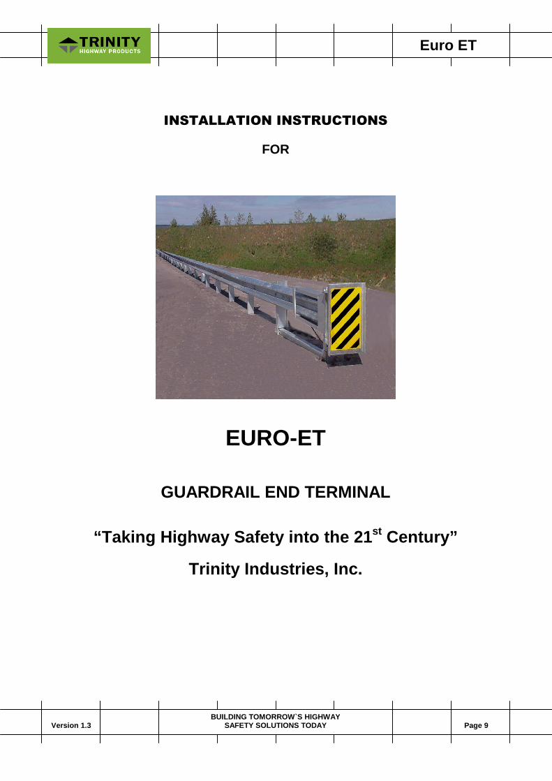
INSTALLATION INSTRUCTIONS
FOR
EURO-ET
GUARDRAIL END TERMINAL
“Taking Highway Safety into the 21st Century”
Trinity Industries, Inc.

Euro ET
Version 1.3 Page 10BUILDING TOMORROW`S HIGHWAY
SAFETY SOLUTIONS TODAY
EURO-ET
12.0 Meter System
FOR SPECIFIC DETAILS, REFER TO TRINITY DRAWING SS-328
BILL OF MATERIAL
NO PC DESCRIPTION________________________________
EU995/995A 1 EURO-ET GUARDRAIL EXTRUDER HEADEU9/10629G 2 EURO-ET STANDARD GUARDRAIL 3.0MM/4.0/2.0/SEU32/29G 1 EURO-ET ANCHOR GUARDRAIL 3.0MM/4.0/2.0/SEU704/704A 1 EURO-ET CABLE ANCHOR BRACKETEU782/782G 1 EURO-ET BEARING PLATE 200MM x 200MM x 16MMEU104/33462A 1 EURO-ET HBA POST #1 TOPEU105/33877A 1 EURO-ET HBA POST #2 TOPEU103/33873A 2 EURO-ET HBA POST #1-#2 STUBEU102/33463G 1 EURO-ET ANGLE STRUT 2062MMEU101/33464G 2 EURO-ET FLANGE PLATE 5MM x 70MM x 100MMEU107/6183G 4 EURO-ET POSTS C120 x 2000MEU106/33461G 4 EURO-ET BRACKET U200EU4254/4254G 8 10MM WASHERSEU4261/4261G 4 10MM x 40MM HEX HD BOLTEU4258/4258G 8 10MM LOCKWASHEREU6321/6321G 4 10MM x 50MM HEX HEAD BOLTEU6405/6405G 8 10MM HEX NUTEU3701/3701G 7 20MM WASHEREU4699/4699G 4 20MM LOCKWASHEREU3704/3704G 4 20MM HEX NUTEU3717/3717G 3 20MM x 65MM HIGH STRENGTH HEX HEAD BOLTEU3718/3718G 1 20MM x 75MM HIGH STRENGTH HEX HEAD BOLT (POST#2)EU3000/3000G 1 CABLE ASSEMBLYEU3300/3300G 5 16MM WASHEREU3340/3340G 29 16MM DOUBLE RECESS NUTEU3360/3360G 24 16MM x 30MM GUARDRAIL SPLICE BOLTSEU3400/3400G 5 16MM x 40MM GUARDRAIL POST BOLTSEU3900/3900G 2 24MM WASHEREU3910/3910G 2 24MM HEX NUT________________________________________________________________
DELINEATION OPTIONS
EU6668/6668B 2 OBJECT MARKER 300MM x 300MM DECAL
Euro ET
Version 1.3 Page 11BUILDING TOMORROW`S HIGHWAY
SAFETY SOLUTIONS TODAY
INSTALLING THE EURO-ET
MATERIALS
As packaged, your EURO-ET system includes all materials needed for a completeinstallation. This will include a 12.0 meter pay limit. Note that concrete footings orfoundations are not required.
SITE PREPARATION
When the guardrail is installed in-line with edge of the shoulder (without any offset),a 50:1 (25:1 taper can be used) taper is recommended so the extruder head will notencroach on the shoulder. Minor site grading may be necessary for the installationsbeyond the edge of the shoulder to prevent the HBA Posts from extending more than100 mm above the ground.
TOOLS REQUIRED
Tools required are those ordinarily used to install standard highway guardrail (HGR).They include 10mm, 16mm, 20mm and 25mm wrenches and such other equipmentas augers and post drivers commonly used in driving posts.
INSTALLATION
Be sure adequate time is allowed for “Same Day” complete installation.
DELINEATION OPTION FOR THE EURO-ET
Two high intensity object markers (EU6667) are installed on the front face of theEURO-ET Guardrail Extruder Head. The delineation object marker is an option tothe EURO-ET and needs to be ordered separately from the EURO-ET package.
Euro ET
Version 1.3 Page 12BUILDING TOMORROW`S HIGHWAY
SAFETY SOLUTIONS TODAY
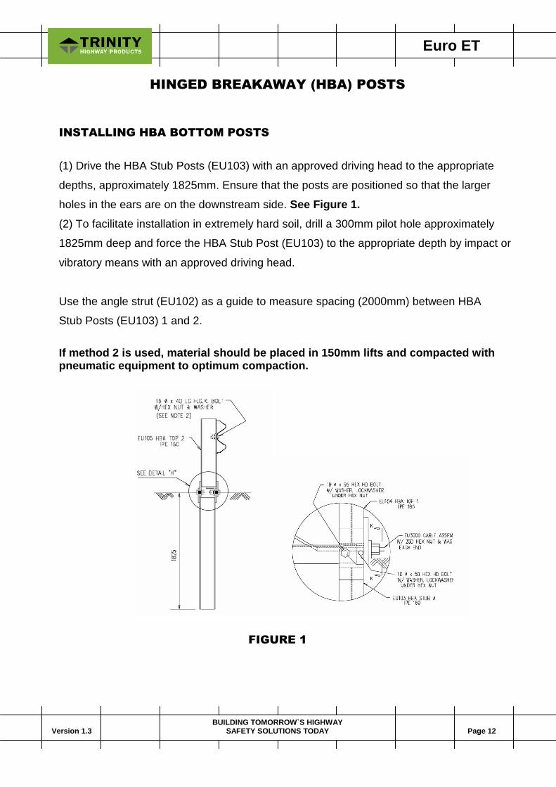
HINGED BREAKAWAY (HBA) POSTS
INSTALLING HBA BOTTOM POSTS
(1) Drive the HBA Stub Posts (EU103) with an approved driving head to the appropriate
depths, approximately 1825mm. Ensure that the posts are positioned so that the larger
holes in the ears are on the downstream side. See Figure 1.
(2) To facilitate installation in extremely hard soil, drill a 300mm pilot hole approximately
1825mm deep and force the HBA Stub Post (EU103) to the appropriate depth by impact or
vibratory means with an approved driving head.
Use the angle strut (EU102) as a guide to measure spacing (2000mm) between HBA
Stub Posts (EU103) 1 and 2.
If method 2 is used, material should be placed in 150mm lifts and compacted withpneumatic equipment to optimum compaction.
FIGURE 1

Euro ET
Version 1.3 Page 13BUILDING TOMORROW`S HIGHWAY
SAFETY SOLUTIONS TODAY
INSTALLING HBA TOP POSTS
Once the HBA Stub Posts are installed, the upper post can now be installed. At PostNo. 1, install the upper post (EU104) by aligning the holes of the ears on the upper andlower posts. In the 11mm holes, install a 10mm diameter x 50mm hex head bolt (EU6321)with a 10mm washer (EU4254), 10mm lock washer (EU4258) under the 10mm hex nut(EU6405G). See Figure 1. The bolts should be installed so the nuts are on the inside ofthe ears. See Figure 3. In the 21mm holes, install a 20mm diameter x 65mm hex headhigh strength bolt (EU3717) with a 20mm washer (EU3701), 20mm lock washer (EU4699)under the 20mm hex nut (EU3704). There is no torque requirement for these bolts.They should be tightened to a snug position. Do not install the bolt on the traffic side untilthe strut is ready to be installed.
FIGURE 2
Attach the Flange Plates (EU101) to the centre holes of the HBA upper post 1 (EU104)
flanges with a 10mm x 40mm hex head bolt (EU4261) and 10mm hex nut (EU6405) with
a 10mm round washer (EU4254) under the bolt head and a 10mm lock washer (EU4258)
under the hex nut. See Figure 2.

Euro ET
Version 1.3 Page 14BUILDING TOMORROW`S HIGHWAY
SAFETY SOLUTIONS TODAY
At Post No. 2, install the upper post (EU105) by aligning the holes of the ears on the
upper and lower posts. In the 11mm holes, install a 10mm diameter x 50mm hex head
bolt (EU6321) with a 10mm washer (EU4254), 10mm lock washer (EU4258) under the
10mm hex nut (EU6405). The bolts should be installed so the nuts are on the inside of
the ears. See Figure 3. In the 21mm holes, install a 20mm diameter x 65mm hex head
high strength bolt (EU3717) with a 20mm washer (EU3701), 20mm lock washer (EU4699)
under the 20mm) hex nut (EU3704). There is no torque requirement for these bolts.
They should be tightened to a snug position.
Do not install the bolt on the traffic side until the strut is ready to be installed.
FIGURE 3
INSTALLING THE STRUT
Place the angle iron strut (EU102) between HBA stub posts (EU103) at the base of
posts 1 and 2. At Post No. 1, a 20mm x 65mm hex head bolt (EU3717) is used to
attach the strut to the post. At post No. 2, a 20mm x 75mm hex head bolt (EU3718)
is used to attach the strut to the post. The bolts should be installed from the traffic side.
At Post No. 1, a 20mm washer (EU3701) and 20mm lock washer (EU4699) are placed
between the 20mm hex nut (EU3704) and the strut. See Figure 1. At Post No. 2, three
(3) 20 mm washers (EU3701) and a 20mm lock washer (EU4699), are placed between the
20mm hex nut (EU3704) and the strut. See Figure 3. There is no torque requirement for
these bolts. They should be tightened to a snug position.
Euro ET
Version 1.3 Page 15BUILDING TOMORROW`S HIGHWAY
SAFETY SOLUTIONS TODAY
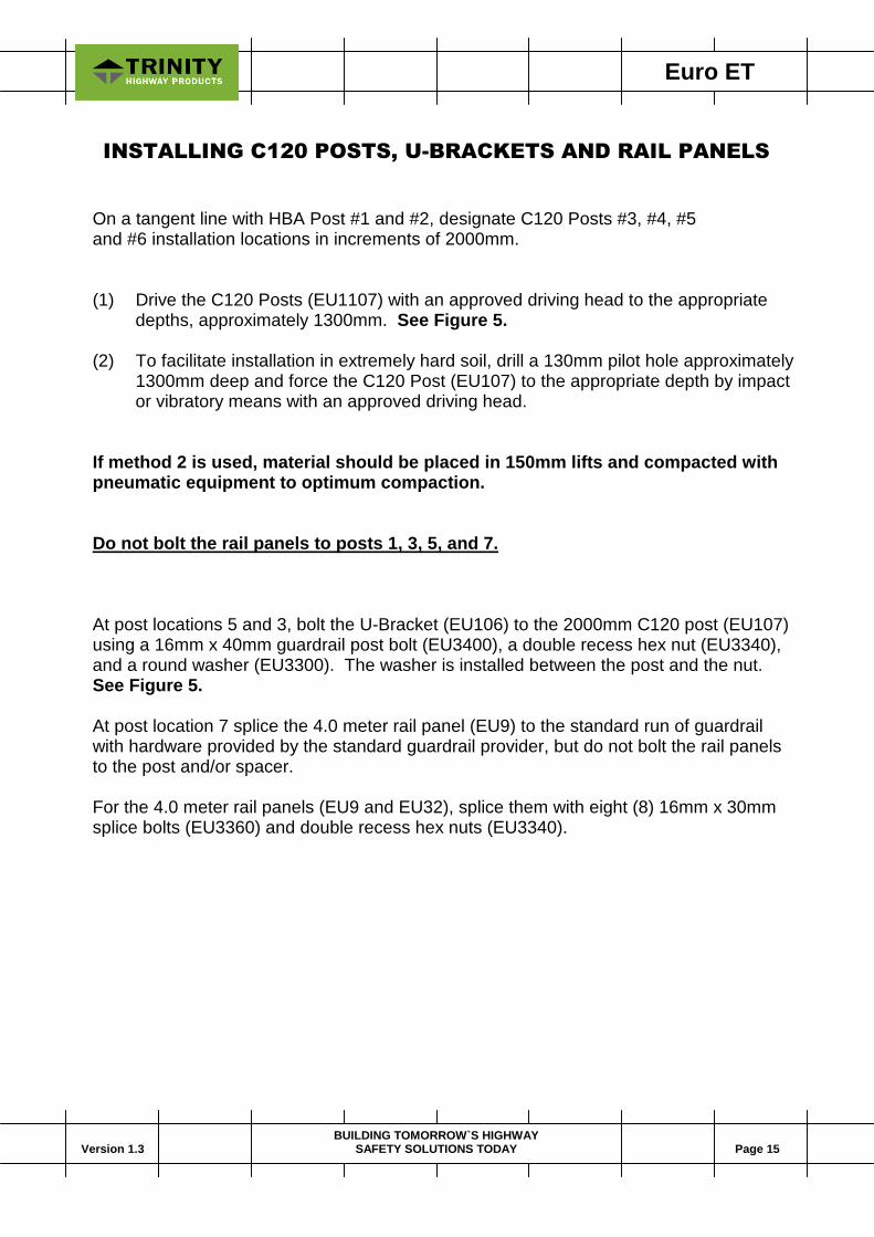
INSTALLING C120 POSTS, U-BRACKETS AND RAIL PANELS
On a tangent line with HBA Post #1 and #2, designate C120 Posts #3, #4, #5and #6 installation locations in increments of 2000mm.
(1) Drive the C120 Posts (EU1107) with an approved driving head to the appropriatedepths, approximately 1300mm. See Figure 5.
(2) To facilitate installation in extremely hard soil, drill a 130mm pilot hole approximately1300mm deep and force the C120 Post (EU107) to the appropriate depth by impactor vibratory means with an approved driving head.
If method 2 is used, material should be placed in 150mm lifts and compacted withpneumatic equipment to optimum compaction.
Do not bolt the rail panels to posts 1, 3, 5, and 7.
At post locations 5 and 3, bolt the U-Bracket (EU106) to the 2000mm C120 post (EU107)using a 16mm x 40mm guardrail post bolt (EU3400), a double recess hex nut (EU3340),and a round washer (EU3300). The washer is installed between the post and the nut.See Figure 5.
At post location 7 splice the 4.0 meter rail panel (EU9) to the standard run of guardrailwith hardware provided by the standard guardrail provider, but do not bolt the rail panelsto the post and/or spacer.
For the 4.0 meter rail panels (EU9 and EU32), splice them with eight (8) 16mm x 30mmsplice bolts (EU3360) and double recess hex nuts (EU3340).
Euro ET
Version 1.3 Page 16BUILDING TOMORROW`S HIGHWAY
SAFETY SOLUTIONS TODAY
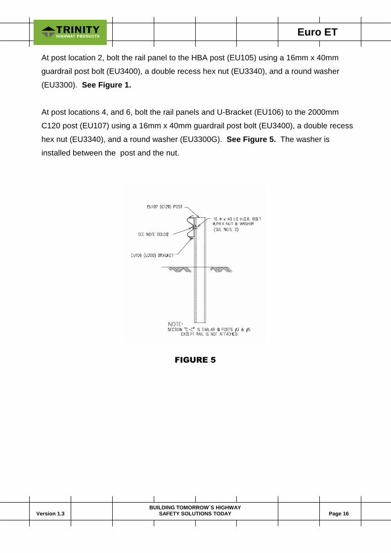
At post location 2, bolt the rail panel to the HBA post (EU105) using a 16mm x 40mm
guardrail post bolt (EU3400), a double recess hex nut (EU3340), and a round washer
(EU3300). See Figure 1.
At post locations 4, and 6, bolt the rail panels and U-Bracket (EU106) to the 2000mm
C120 post (EU107) using a 16mm x 40mm guardrail post bolt (EU3400), a double recess
hex nut (EU3340), and a round washer (EU3300G). See Figure 5. The washer is
installed between the post and the nut.
FIGURE 5
Euro ET
Version 1.3 Page 17BUILDING TOMORROW`S HIGHWAY
SAFETY SOLUTIONS TODAY
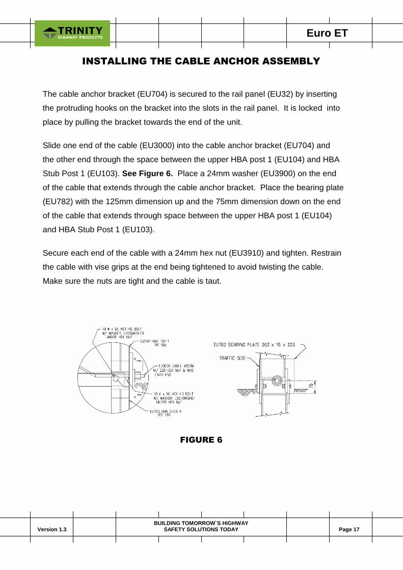
INSTALLING THE CABLE ANCHOR ASSEMBLY
The cable anchor bracket (EU704) is secured to the rail panel (EU32) by inserting
the protruding hooks on the bracket into the slots in the rail panel. It is locked into
place by pulling the bracket towards the end of the unit.
Slide one end of the cable (EU3000) into the cable anchor bracket (EU704) and
the other end through the space between the upper HBA post 1 (EU104) and HBA
Stub Post 1 (EU103). See Figure 6. Place a 24mm washer (EU3900) on the end
of the cable that extends through the cable anchor bracket. Place the bearing plate
(EU782) with the 125mm dimension up and the 75mm dimension down on the end
of the cable that extends through space between the upper HBA post 1 (EU104)
and HBA Stub Post 1 (EU103).
Secure each end of the cable with a 24mm hex nut (EU3910) and tighten. Restrain
the cable with vise grips at the end being tightened to avoid twisting the cable.
Make sure the nuts are tight and the cable is taut.
FIGURE 6
Euro ET
Version 1.3 Page 18BUILDING TOMORROW`S HIGHWAY
SAFETY SOLUTIONS TODAY
INSTALLING THE GUARDRAIL EXTRUDER
The final piece to attach is the guardrail extruder head (EU995). Place the extruder
head over the end of the rail panel (EU32). The extruder head can be used on the
left or right hand shoulder. Be sure the exit slot is on the backside, away from traffic.
The extruder head should be pushed on the rail panel as far as it will go, making
sure that the end edge of the guardrail is completely inside the extruder head.
Center the rail in the tail of the extruder.
The attachment brackets have 3 holes in each bracket to provide tolerance in the
installation. Choose the hole in the bracket that is closest to the predrilled hole in
the post while making sure that the edge end of the guardrail is completely inside
the extruder head. Secure the extruder with a 10mm x 40mm hex head bolt
(EU4281) and a washer (EU4254) under the bolt head and lock washer (EU4258)
between the nut (EU6405) and the post at the top and bottom brackets.

Euro ET
Version 1.3 Page 19BUILDING TOMORROW`S HIGHWAY
SAFETY SOLUTIONS TODAY
EURO-ET
INSTALLATION CHECK LIST
COUNTRY: ____________________________________________________________DATE: ________________________________________________________________PROJECT: _____________________________________________________________LOCATION: ____________________________________________________________
o The rail height is in accordance with the plans (generally 700mm to 750mm)above the edge of the shoulder or the ground line).
o The 20mm hex head bolts that connect the HBA stub posts to the HBA top postsare at ground level and HBA stub posts do not protrude more than100mm abovethe ground line (measured by the AASHTO 1.5m cord method). Site grading maybe necessary to meet this requirement.
o The 20mm hex head bolts that connect the HBA stub posts to the HBA top postsare tightened to a snug position.
o The end of the guardrail is butted up to the beginning of the bending slot inside theextruder head.
o The first HBA post is the only one with holes for attaching the extruder head andhas connecting plates cut at a 45 degree angle.
o The 200mm x 200mm bearing plate at post 1 is correctly positioned and the anchorcable is taut and correctly installed (it should be rechecked after installation to besure it hasn’t relaxed).
o The backfill material around the posts is properly compacted.
o Each HBA post has two bolts on either side of the post and should be oriented sothat the larger bolt is downstream of the smaller bolt.
o The rail panels are not attached to the posts at locations identified for thesystem installed.
o The object marker is correctly positioned on the extruder face.
SIGNATURE:________________________________________________________

Euro ET
Version 1.3 Page 20BUILDING TOMORROW`S HIGHWAY
SAFETY SOLUTIONS TODAY
MAINTENANCE/REPAIR INSTRUCTIONS FOR
EURO-ETGUARDRAIL END TERMINAL
MAINTENANCE
Maintenance consists of periodically checking the system to see that the cable is taut,
the nuts have not been removed from the cable.
REPAIR
1) At the accident site, remove any debris that has encroached onto the traveled way
or shoulder. Install any necessary delineation for the damaged system. Take
inventory of the damaged system and determine what parts are reusable and what
parts need to be replaced. Check the extruder head for damage. It is normally
reusable. Check the anchor cable and bracket for damage. The bearing plate,
nuts and washers, and anchor bracket are rarely damaged.
2) Obtain those parts that need to be replaced.
3) With the replacement parts, return to the repair site.
4) Burn off the extruded rail near the extruder head. Attach a chain to the extruder
head. Pull the extruder off of the rail with the chain attached to a truck frame while the
other end of the rail is still tied to the down-stream posts that provide an anchor.
5) Remove any damaged rail that has to be replaced.
6) Remove any damaged posts C120 posts and U-Brackets.
7) Remove any damaged Hinged Breakaway (HBA) posts.
8) After the site has been cleared of damaged debris, the system can bereconstructed following the installation instructions.
Euro ET
Version 1.3 Page 21BUILDING TOMORROW`S HIGHWAY
SAFETY SOLUTIONS TODAY
EQUIPMENT NEEDED FOR REPAIR OPERATION
1) Acetylene torch to cut off extruded rail.
2) Heavy duty chain to remove the extruder along with a chain hook up as
recommended (see below).
3) S.A.E. wrench or proper socket sizes.
4) Vice grip or channel lock pliers and sledge hammer.
5) Vehicle to pull the extruder off from the damaged rail.
TRINITY INDUSTRIES, INC.HIGHWAY SAFETY PRODUCTS
It has been demonstrated by crash testing that Trinity Industries, Inc.’s EURO-ETGuardrail Terminal meets the requirements of prEN 1317-4 Level P4.
Euro ET
Version 1.3 Page 22BUILDING TOMORROW`S HIGHWAY
SAFETY SOLUTIONS TODAY
Annex 1Drawings

Euro ET
Version 1.3 Page 23BUILDING TOMORROW`S HIGHWAY
SAFETY SOLUTIONS TODAY
Euro ET
Version 1.3 Page 24BUILDING TOMORROW`S HIGHWAY
SAFETY SOLUTIONS TODAY
Annex 2In-Service Evaluation

Euro ET
Version 1.3 Page 25BUILDING TOMORROW`S HIGHWAY
SAFETY SOLUTIONS TODAY
Euro ET
Version 1.3 Page 26BUILDING TOMORROW`S HIGHWAY
SAFETY SOLUTIONS TODAY
Euro ET
Version 1.3 Page 27BUILDING TOMORROW`S HIGHWAY
SAFETY SOLUTIONS TODAY
Euro ET
Version 1.3 Page 28BUILDING TOMORROW`S HIGHWAY
SAFETY SOLUTIONS TODAY
Euro ET
Version 1.3 Page 29BUILDING TOMORROW`S HIGHWAY
SAFETY SOLUTIONS TODAY

Euro ET
Version 1.3 Page 30BUILDING TOMORROW`S HIGHWAY
SAFETY SOLUTIONS TODAY

Euro ET
Version 1.3 Page 31BUILDING TOMORROW`S HIGHWAY
SAFETY SOLUTIONS TODAY

Euro ET
Version 1.3 Page 32BUILDING TOMORROW`S HIGHWAY
SAFETY SOLUTIONS TODAY