Embed Size (px)
Citation preview

EuratomTORE SUPRA
G. Bosia Proposals for the ITER IC System R&D CCFW 37 - 23 /11/2004
Proposals for ITER IC systems R&D developments
G. Bosia, B. Beaumont, S. Brémond, K.Vulliez
Association Euratom-CEA, CEA/DSM/DRFC, CEA/Cadarache, F-13108 SAINT PAUL LEZ DURANCE.

EuratomTORE SUPRA
G. Bosia Proposals for the ITER IC System R&D CCFW 37 - 23 /11/2004
The CEA program for the development of the The CEA program for the development of the ITER IC systemITER IC system
• The CEA program for the ITER Ion Cyclotron System R&D development is carried out since year 2000 on voluntary basis and funding.
• The goal of this program is to address operational issues complementary to the JET EP program, in particular related to high power, long pulse operation, which do not seem to concern too much the IC Community at present.
• We instead believe that these issues could be potential show stoppers for IC in ITER and should be resolved during ITER construction period. These issue can be experimentally addressed on TS.
• We also believe that it is high time that a serious R&D program is started to develop ITER Ion Cyclotron heating system. ITER equipment should be prototyped and tested to be available for procurement

EuratomTORE SUPRA
G. Bosia Proposals for the ITER IC System R&D CCFW 37 - 23 /11/2004
ICH ITER issue no. 1 - Plasma coupling
10
5
2
1
0.10 0.12 0.14 0.16 0.18 0.20
gap (m)
R’
(ohm/m)RANT 3Dphasing, 53.0
MHz)
• At the nominal antenna loading (R’ = 4 /m), obtained in a “quiet” H-mode plasma with LCS at 12 cm from the first wall, and 10 MW/m2, the antenna maximum field in the torus “vacuum” is in excess of Emax < 2 kV/mm .
• However, there is no guarantee that the ITER IC array will actually operate at the nominal gap.
• We regard as important to significantly reduce the max operating E-field

EuratomTORE SUPRA
G. Bosia Proposals for the ITER IC System R&D CCFW 37 - 23 /11/2004
ICH ITER issue no. 2 – Torus “vacuum”
.
• 2 kV/mm peak is approximately the RF breakdown voltage of today best experiments in a neutral pressure that never exceeds 10-4 torr .
• However there is no guarantee that the ITER IC array will actually operate at a neutral pressure below 10-4 torr, as it is assumed in some ITER paper.
In ITER the neutral pressure at the first wall is enhanced by the large wall loading and, compared with present experiments it is likely to be higher of an amount difficult to predict,as this critically depends on local sources distribution and molecular flow.
We regard as important to improve the “torus vacuum” in the areas of high E-fields

EuratomTORE SUPRA
G. Bosia Proposals for the ITER IC System R&D CCFW 37 - 23 /11/2004
IC ITER issue no. 3 – RF power losses in plasma edge• A non negligible fraction of the ICH power is lost in the plasma edge and could be
responsible for experimentally observed local effects of hot spots, ions acceleration, further wall loading and production of metal impurities. • Sheath potentials generated by non-linear E-field rectification in the neighborhood of the IC antenna are thought to be the prime cause of the edge power losses.
• For a simple strap, the sheath voltage is proportional to the strap current, and reducing the strap voltage is of no use, to minimize sheath potentials
• We regard as important to minimize sheath potentials ions kinetic energy below the level of sputtering by optimising the antenna geometry.
EuratomTORE SUPRA
G. Bosia Proposals for the ITER IC System R&D CCFW 37 - 23 /11/2004
IC ITER issue no. 4 – Array RF currents control
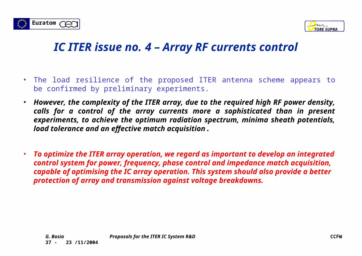
• The load resilience of the proposed ITER antenna scheme appears to be confirmed by preliminary experiments.
• However, the complexity of the ITER array, due to the required high RF power density, calls for a control of the array currents more a sophisticated than in present experiments, to achieve the optimum radiation spectrum, minima sheath potentials, load tolerance and an effective match acquisition.
• To optimize the ITER array operation, we regard as important to develop an integrated control system for power, frequency, phase control and impedance match acquisition, capable of optimising the IC array operation. This system should also provide a better protection of array and transmission against voltage breakdowns.
EuratomTORE SUPRA
G. Bosia Proposals for the ITER IC System R&D CCFW 37 - 23 /11/2004
Proposed ITER Array Design Upgrade(s)
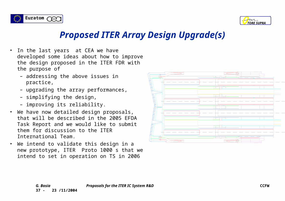
• In the last years at CEA we have developed some ideas about how to improve the design proposed in the ITER FDR with the purpose of
– addressing the above issues in practice,
– upgrading the array performances,
– simplifying the design,
– improving its reliability.
• We have now detailed design proposals, that will be described in the 2005 EFDA Task Report and we would like to submit them for discussion to the ITER International Team.
• We intend to validate this design in a new prototype, ITER Proto 1000 s that we intend to set in operation on TS in 2006
EuratomTORE SUPRA
G. Bosia Proposals for the ITER IC System R&D CCFW 37 - 23 /11/2004
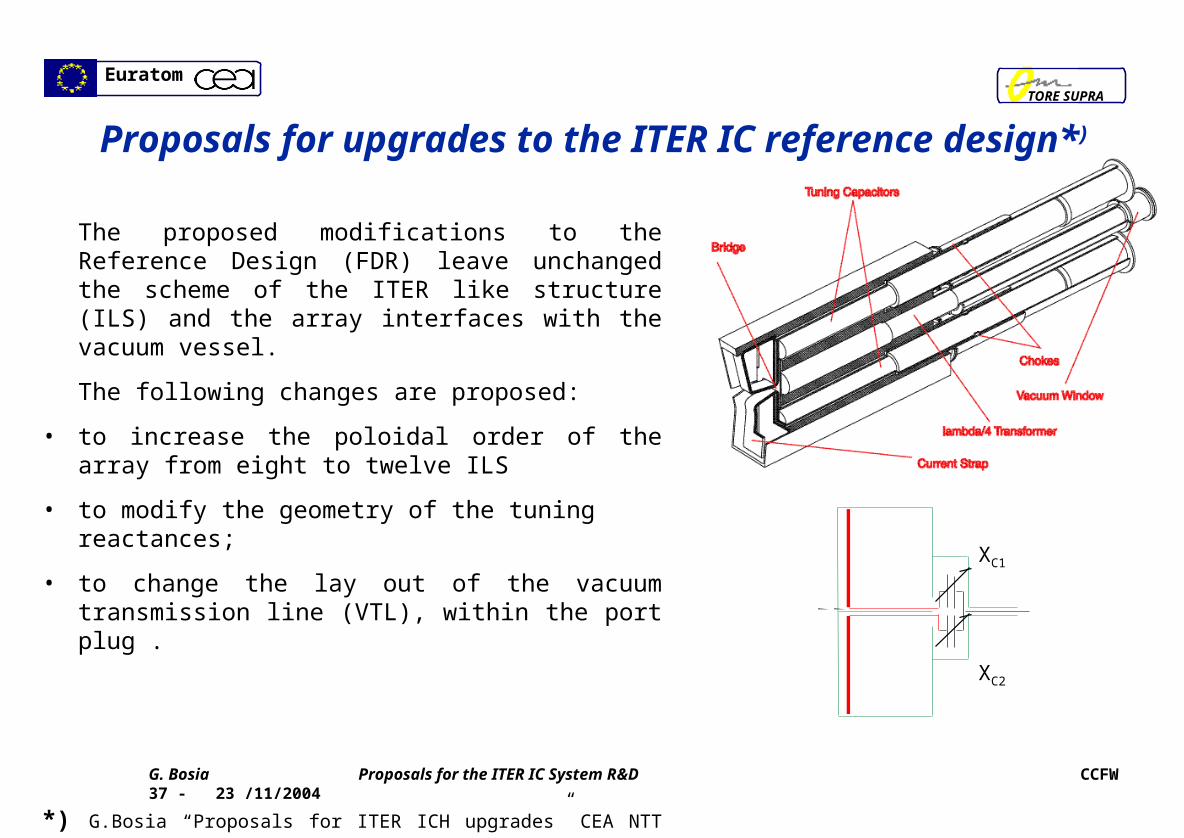
The proposed modifications to the Reference Design (FDR) leave unchanged the scheme of the ITER like structure (ILS) and the array interfaces with the vacuum vessel.
The following changes are proposed:
• to increase the poloidal order of the array from eight to twelve ILS
• to modify the geometry of the tuning reactances;
• to change the lay out of the vacuum transmission line (VTL), within the port plug .
*) G.Bosia “Proposals for ITER ICH upgrades” CEA NTT xxxxx (2004)
XC1
XC2
Proposals for upgrades to the ITER IC reference design*)
EuratomTORE SUPRA
G. Bosia Proposals for the ITER IC System R&D CCFW 37 - 23 /11/2004
Increase the array poloidal order of the from 8 to 12 ILS
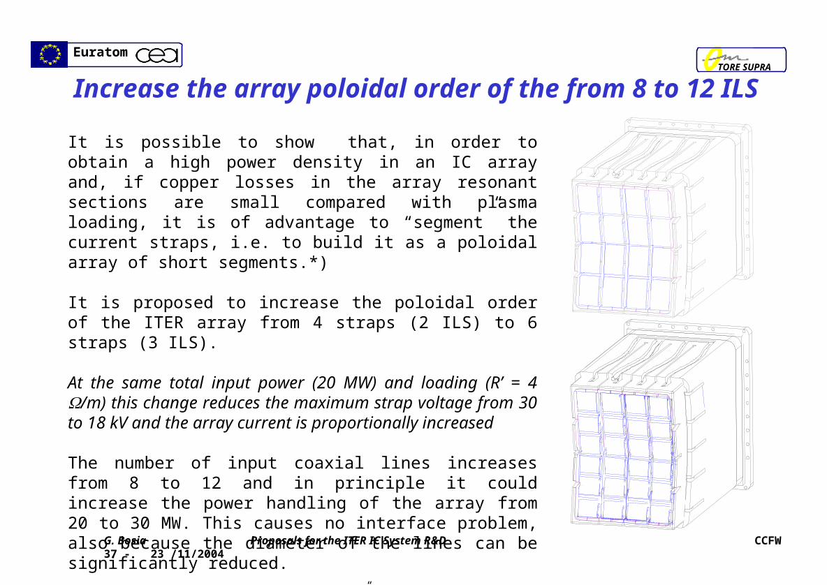
It is possible to show that, in order to obtain a high power density in an IC array and, if copper losses in the array resonant sections are small compared with plasma loading, it is of advantage to “segment” the current straps, i.e. to build it as a poloidal array of short segments.*)
It is proposed to increase the poloidal order of the ITER array from 4 straps (2 ILS) to 6 straps (3 ILS).
At the same total input power (20 MW) and loading (R’ = 4 /m) this change reduces the maximum strap voltage from 30 to 18 kV and the array current is proportionally increased
The number of input coaxial lines increases from 8 to 12 and in principle it could increase the power handling of the array from 20 to 30 MW. This causes no interface problem, also because the diameter of the lines can be significantly reduced.
*G. Bosia “Properties of IC segmented antennas” (Proc of Moran Technical meeting, 2003)
EuratomTORE SUPRA
G. Bosia Proposals for the ITER IC System R&D CCFW 37 - 23 /11/2004
Replace short circuited stubs
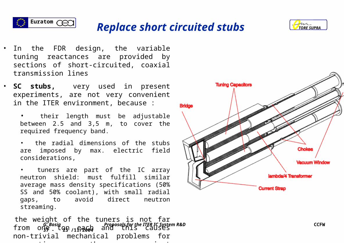
• In the FDR design, the variable tuning reactances are provided by sections of short-circuited, coaxial transmission lines
• SC stubs, very used in present experiments, are not very convenient in the ITER environment, because :
• their length must be adjustable between 2.5 and 3,5 m, to cover the required frequency band.
• the radial dimensions of the stubs are imposed by max. electric field considerations,
• tuners are part of the IC array neutron shield: must fulfill similar average mass density specifications (50% SS and 50% coolant), with small radial gaps, to avoid direct neutron streaming.
the weight of the tuners is not far from one ton each and this causes non-trivial mechanical problems for supporting them against electromagnetic and inertial loads.
EuratomTORE SUPRA
G. Bosia Proposals for the ITER IC System R&D CCFW 37 - 23 /11/2004
SlidersStrap input
Strap input
Remove stubs chokes
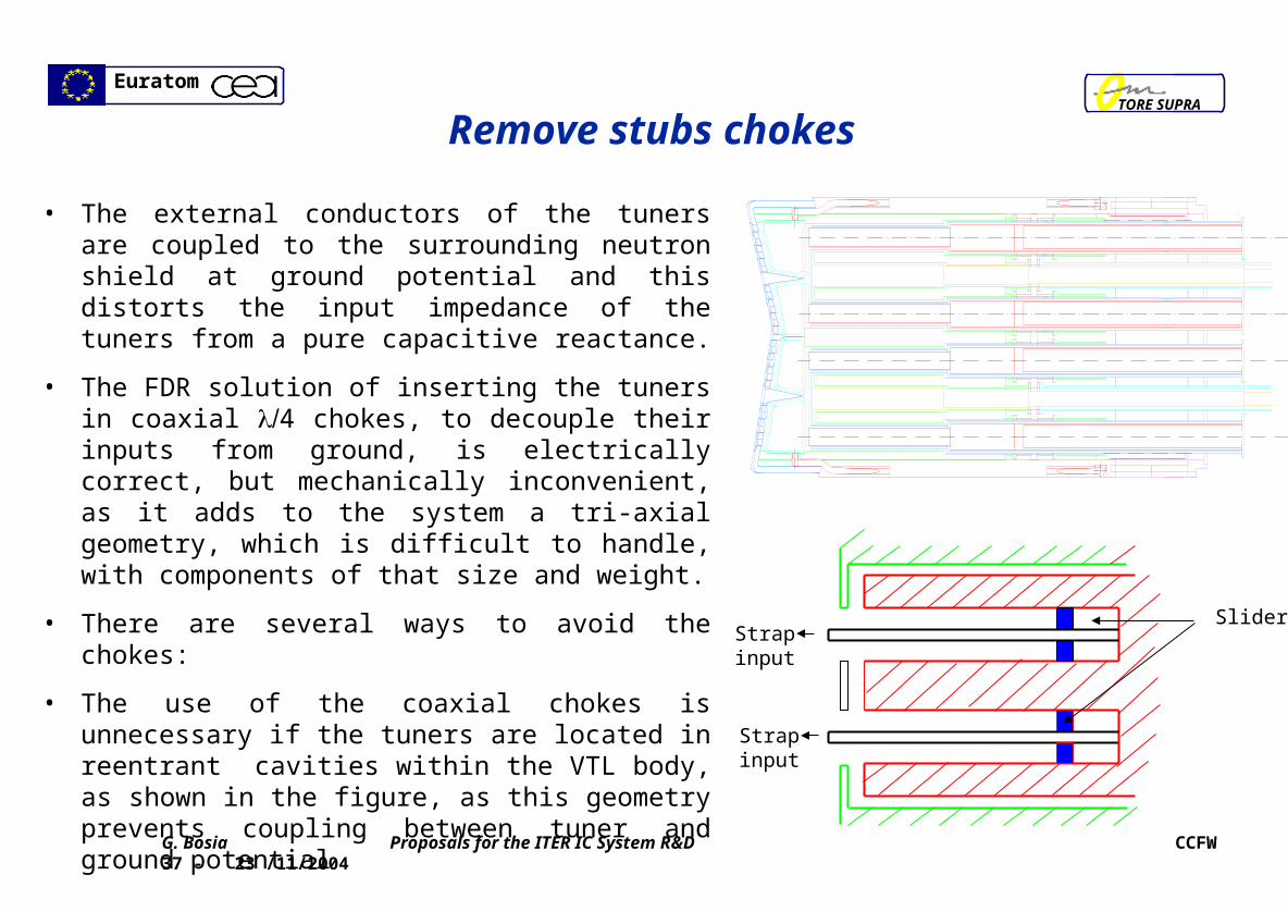
• The external conductors of the tuners are coupled to the surrounding neutron shield at ground potential and this distorts the input impedance of the tuners from a pure capacitive reactance.
• The FDR solution of inserting the tuners in coaxial 4 chokes, to decouple their inputs from ground, is electrically correct, but mechanically inconvenient, as it adds to the system a tri-axial geometry, which is difficult to handle, with components of that size and weight.
• There are several ways to avoid the chokes:
• The use of the coaxial chokes is unnecessary if the tuners are located in reentrant cavities within the VTL body, as shown in the figure, as this geometry prevents coupling between tuner and ground potential

EuratomTORE SUPRA
G. Bosia Proposals for the ITER IC System R&D CCFW 37 - 23 /11/2004
Use capacitively loaded stubs
A variable-length open-circuit transmission line would :
• reduce the length of the tuner to less than one meter, • not require metallic sliders operating in vacuum, • be submitted to a Vmax sin(2l/), voltage profile as function of length similar to one of
the short circuited stub, but terminated at voltage significantly lower than the maximum voltage (for ITER typical parameters and power densities, higher than 40 kV)
A way to further reduce the length of the tuner and the max voltage is to load the coaxial line at the end by a variable capacitor, as shown in the figure. This also reduces the variable length of the tuner to few centimeters.
d
CC
Torus vacuum
Improved vacuumDielectric septum
Zin
Zc
XC

EuratomTORE SUPRA
G. Bosia Proposals for the ITER IC System R&D CCFW 37 - 23 /11/2004
Matching range Matching range
• For ITER typical load parameters the tuning capacitor has dimensions comparable with TS COMET capacitors
l .
14 16 18 20 22 2420
30
40
50
60
70
80
90
matching reactance Xin (ohm)
Load c
ap
acit
ance (
pF
)
l = 0.3m l = 0.4m l = 0.5m l = 0.6m
0.07 0.075 0.08 0.085 0.09 0.095 0.1 0.10520
30
40
50
60
70
80
90
axial displacement (m)
inpu
t rea
ctan
ce (o
hm)
.
.
n =1
n =2
n =3
n =4
n =5
EuratomTORE SUPRA
G. Bosia Proposals for the ITER IC System R&D CCFW 37 - 23 /11/2004
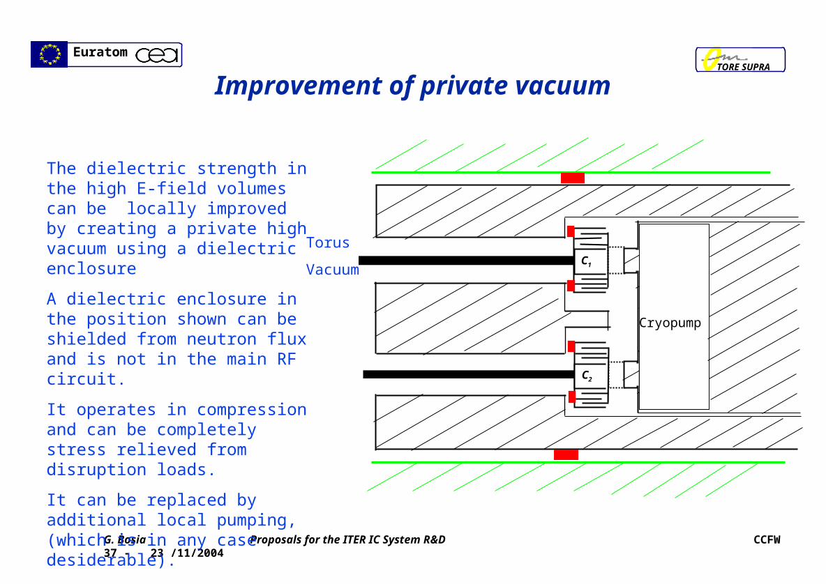
Improvement of private vacuum
Torus
Vacuum
The dielectric strength in the high E-field volumes can be locally improved by creating a private high vacuum using a dielectric enclosure
A dielectric enclosure in the position shown can be shielded from neutron flux and is not in the main RF circuit.
It operates in compression and can be completely stress relieved from disruption loads.
It can be replaced by additional local pumping, (which is in any case desiderable).
C1
C2
Cryopump
EuratomTORE SUPRA
G. Bosia Proposals for the ITER IC System R&D CCFW 37 - 23 /11/2004
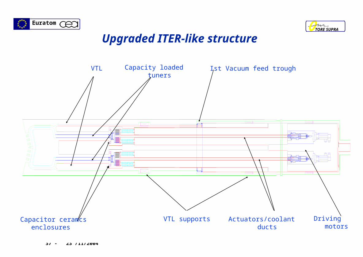
Upgraded ITER-like structure
VTL Capacity loaded tuners Ist Vacuum feed trough
VTL supportsCapacitor ceramcs enclosures Actuators/coolant ducts Driving motors
EuratomTORE SUPRA
G. Bosia Proposals for the ITER IC System R&D CCFW 37 - 23 /11/2004
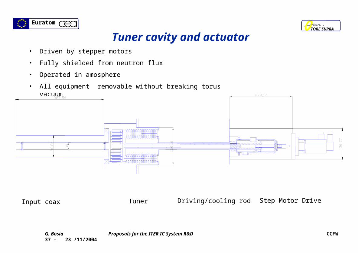
Tuner cavity and actuator
Input coax Tuner Driving/cooling rod Step Motor Drive
• Driven by stepper motors
• Fully shielded from neutron flux
• Operated in amosphere
• All equipment removable without breaking torus vacuum

EuratomTORE SUPRA
G. Bosia Proposals for the ITER IC System R&D CCFW 37 - 23 /11/2004
Tuning Capacitor
• 3 cm stroke
• Small high vacuum volume
• Water cooled at blanket temperature
• Shielded from neutron flux
• Stress relieved from disruption loads

EuratomTORE SUPRA
G. Bosia Proposals for the ITER IC System R&D CCFW 37 - 23 /11/2004
Ceramic feed-through
• Fully shielded from neutron flux
• Fully stress relieved
• High vacuum on both ends
• Ceramic (possibly) only conduction cooled

EuratomTORE SUPRA
G. Bosia Proposals for the ITER IC System R&D CCFW 37 - 23 /11/2004
Array modules separable without breaking torus vacuum

EuratomTORE SUPRA
G. Bosia Proposals for the ITER IC System R&D CCFW 37 - 23 /11/2004
Reference and upgraded layouts
b)
a)

EuratomTORE SUPRA
G. Bosia Proposals for the ITER IC System R&D CCFW 37 - 23 /11/2004
Geometry of ITER IC array module and TS Proto 1000 s
The ITER design proposal is the basis for our next TS ITER prototype 1000s, which is dimensionally similar to a four straps ITER array module, and can include all equipment used in the ITER array, to be realistically tested in TS operation.

EuratomTORE SUPRA
G. Bosia Proposals for the ITER IC System R&D CCFW 37 - 23 /11/2004
Performances @ 2f Performances @ 2f CtCt= 53 MHz 20 MW/ port= 53 MHz 20 MW/ port
Parameter Reference Upgrade
Tuning reactances () 46.1 & 37.8
Voltage at the strap feeder input (kV) 28 17 and 16
Voltage at tuning capacitor (kV) - < 20
Max Electric field in torus vacuum (kV/mm) 2 1
Max electric field in private vacuum - < 10
• @ 2f @ 2f CtCt= 53 MHz , 20 MW/ port, R’ = 4 = 53 MHz , 20 MW/ port, R’ = 4 /m, /m,

EuratomTORE SUPRA
G. Bosia Proposals for the ITER IC System R&D CCFW 37 - 23 /11/2004
ICH ITER issue no. 1 - Plasma coupling
0.10 0.12 0.14 0.16 0.18 0.20
gap (m)
10
5
2
1
R’
(ohm/m)
RANT 3Dphasing, 53.0 MHz)
• Operation at R’ = 1 /m, i.e. with the LCS at 20 cm from the first wall would be possible with the same performances as the FDR.
• We regard this gain as significant
EuratomTORE SUPRA
G. Bosia Proposals for the ITER IC System R&D CCFW 37 - 23 /11/2004
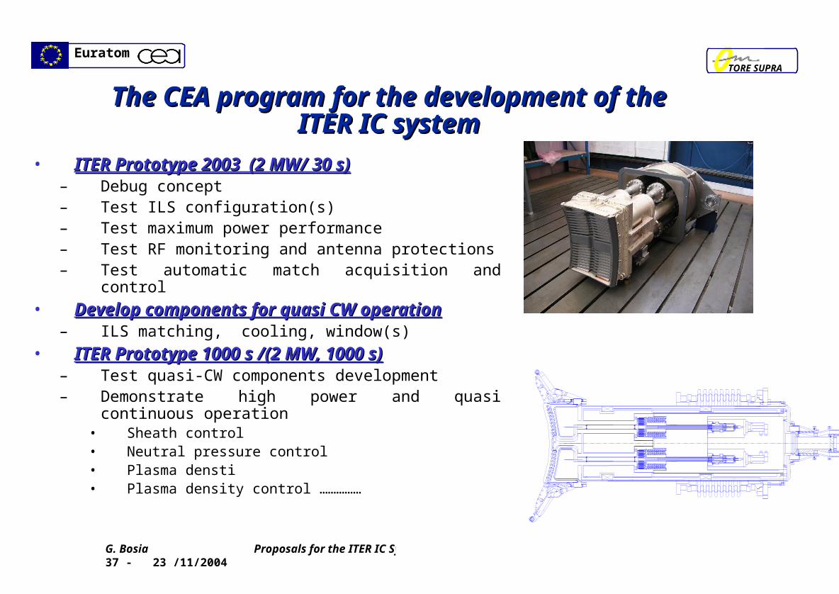
The CEA program for the development of the The CEA program for the development of the ITER IC systemITER IC system
• ITER Prototype 2003 (2 MW/ 30 s)ITER Prototype 2003 (2 MW/ 30 s)– Debug concept – Test ILS configuration(s)– Test maximum power performance– Test RF monitoring and antenna protections– Test automatic match acquisition and control
• Develop components for quasi CW operationDevelop components for quasi CW operation– ILS matching, cooling, window(s)
• ITER Prototype 1000 s /(2 MW, 1000 s)ITER Prototype 1000 s /(2 MW, 1000 s)– Test quasi-CW components development– Demonstrate high power and quasi continuous
operation• Sheath control• Neutral pressure control• Plasma densti• Plasma density control ……………

EuratomTORE SUPRA
G. Bosia Proposals for the ITER IC System R&D CCFW 37 - 23 /11/2004
Array monitoring/control/ protection systemsArray monitoring/control/ protection systems
• The experience of the first operation of the TS ITER proto has evidenced the need for an accurate vectorial control of the IC array currents, to :
– easily acquire match conditions (in particular in vacuum) and to optimise load resilience – detect breakdowns in the resonant part of the circuit, which may be not efficiently detected by usual VSWR
monitors.
• This experiment has guided the design of an integrated monitor/control/protection system (the method is described in the interim report of the current EFDA task) which will be developed in 2005 and installed for evaluation and testing on plasma in next operational run of ITER Proto in 2005
• Monitoring The system operates driven by two impedance monitors per ILS
• Control Input currents vectorially controlled using the two tuners and RF output. forward voltages. Tuning control includes both match trim against “slow” load variations ( >10 ms)
• Protection Breakdown monitors are operated by threshold values imposed on absolute and the differential values of each half sections ( <10 s)
• The method is applicable to arrays of any order. However, the evolution toward the control of a large poloidal/ toroidal array such as the one of ITER, may require the adoption of standard system optimisation techniques applied to the control algorithms, which needs to be further developed.
EuratomTORE SUPRA
G. Bosia Proposals for the ITER IC System R&D CCFW 37 - 23 /11/2004
Development of ITER tuning components Development of ITER tuning components • The operation of the ITER Prototype 1000 s requires the development of tuning
components, tuning actuators, precision position monitors and vacuum feed through with adequate cooling capabilities for CW operation.
• We plan do develop these components starting in 2005, with industry support, to have them available in 2006 (to be included in the ITER Prototype 1000).
• These components can be designed and constructed to be fully compatible with ITER environment and their operation can be extensively tested in the TS Prototype 1000 s in time to be available for use in ITER
• We are ready to agree with EFDA and the ITER IT detailed specifications for these components, so as to make them suitable for potential ITER use, whether or not our design proposals are accepted .

EuratomTORE SUPRA
G. Bosia Proposals for the ITER IC System R&D CCFW 37 - 23 /11/2004
Development of ITER Proto 2001 Development of ITER Proto 2001
No R&D support requested

EuratomTORE SUPRA
G. Bosia Proposals for the ITER IC System R&D CCFW 37 - 23 /11/2004
Proposed program and budget Proposed program and budget
Activity Year R&D Design
Development of integrated array control/protection 2005 50 0.5 PPY
Development of tuners and actuation 2005-2006 300 1.0 PPY
Procurement of 6 production items for TS Proto 1000 2007 150
Ceramic feed troughs 2006 50 0.5 PPY


![arXiv:1705.08041v2 [cs.CV] 18 Dec 2018 · iter iter iter iter Single Iteration: CNN Prior Figure 1: A proximal gradient ODP network for deblurring under Gaussian noise, mapping the](https://img.pdfslide.us/doc/110x75/5f39be22f6fe290b831f0c4a/arxiv170508041v2-cscv-18-dec-2018-iter-iter-iter-iter-single-iteration-cnn.jpg)