Embed Size (px)
Citation preview

arX
iv:a
stro
-ph/
0101
161v
1 1
0 Ja
n 20
01
ON TURBULENT
RECONNECTION
EUN-JIN KIM and P. H. DIAMOND
Department of Physics, University of
California at San Diego, La Jolla, CA 92093,
USA
Received ;
accepted

– 2 –
ABSTRACT
We examine the dynamics of turbulent reconnection in 2D and 3D reduced MHD
by calculating the effective dissipation due to coupling between small–scale fluctua-
tions and large–scale magnetic fields. Sweet–Parker type balance relations are then
used to calculate the global reconnection rate. Two approaches are employed —
quasi–linear closure and an eddy-damped fluid model. Results indicate that despite
the presence of turbulence, the reconnection rate remains inversely proportional to√Rm, as in the Sweet–Parker analysis. In 2D, the global reconnection rate is shown
to be enhanced over the Sweet–Parker result by a factor of magnetic Mach number.
These results are the consequences of the constraint imposed on the global recon-
nection rate by the requirement of mean square magnetic potential balance. The
incompatibility of turbulent fluid–magnetic energy equipartition and stationarity
of mean square magnetic potential is demonstrated.
Subject headings: MHD — magnetic fields — turbulence
1. INTRODUCTION
Magnetic reconnection is the process
whereby large scale magnetic field energy
is dissipated and magnetic topology is
altered in MHD fluids and plasmas (for
instance, see, Vasyliunas 1975; Parker 1979;
Forbes & Priest 1984; Biskamp 1993; Wang,
Ma, & Bhattacharjee 1996 and references
therein). Reconnection is often invoked
as the explanation of large scale magnetic
energy release in space, astrophysical, and
laboratory plasmas. Specifically, magnetic
reconnection is thought to play an integral
role in the dynamics of the magnetotail,
the solar dynamo, solar coronal heating,
and in the major disruption in tokamaks.
For these reasons, magnetic reconnection
has been extensively studied in the context
of MHD, two-fluid and kinetic models, via
theory, numerical simulations and laboratory
experiments.
The basic paradigm for magnetic
reconnection is the Sweet–Parker (called
SP hereafter) problem (Parker 1957; Sweet
1958), in which a steady inflow velocity
advects oppositely directed magnetic field
lines (±B) together, resulting in current
sheet formation and, thus, reconnection (see
Fig. 1). The current sheet has thickness ∆
and length L, so that imposition of continuity
(vrL = v0∆), momentum balance (v0 = vA)
and magnetic energy balance (vrB = ηB/∆)
constrains the inflow, or “reconnection”,
velocity to be vr = vA/√S ∝ vA/
√Rm.
Here v0 is the outflow velocity; vA is the

– 3 –
Alfven speed associated with B; S ≡ vAL/η
is the Lundquist number; Rm = ul/η is
the magnetic Reynolds number, with u
and l being the characteristic amplitude
and length scale of the velocity — S is
called the magnetic Reynolds number
Rm in some literatures. Note that the
SP process forms strangely anisotropic
current sheets since ∆/L =√S and
S ≫ 1. Note also the link between sheet
anisotropy and the reconnection speed vr,
i.e., vr/vA = ∆/L = 1/√S. Finally, it should
be noted that vr is a measure of the global
reconnection rate, in that it parameterizes
the mean inflow velocity to the layer.
The SP Picture is intrinsically appealing,
on account of its simplicity and dependence
only upon conservation laws. Moreover, the
SP prediction has been verified by laboratory
experiments (Ji, Yamada, & Kulsrud 1998).
However, since Rm is extremely large in
most astrophysical applications of interest
(i.e. Rm ∼ 1013 in the solar corona), the
SP reconnection speed is pathetically slow.
Hence, there have been many attempts
to develop models of fast reconnection.
For example, in 1964 Petschek proposed
a fast reconnection model involving shock
formation near the reconnection layer, which
predicted vr = vA/ lnS. Unfortunately,
subsequent numerical (Biskamp 1986)
and theoretical (Kulsrud 2000) study has
indicated that Petschek’s model is internally
inconsistent. While research on fast, laminar
reconnection continues today (i.e., Kleva,
Drake, & Waelbroeck 1995) in the context of
two-fluid models, the failure of the Petschek
scenario has sparked increased interest
in turbulent reconnection (Matthaeus &
Lamkin 1986) in which turbulent transport
coefficients (which can be large for large
Reynolds number) act as effective dissipation
coefficients, and so are thought to facilitate
fast reconnection (i.e., Diamond et al.
1984; Strauss 1988). Interest in turbulent
reconnection has also been stimulated by
the fact that many instances of reconnection
occur in systems where turbulence is
ubiquitous, i.e., coronal heating of turbulent
accretion disks, the dynamo in the sun’s
convection zone, and turbulent tokamak
plasmas during disruptions.
– 4 –
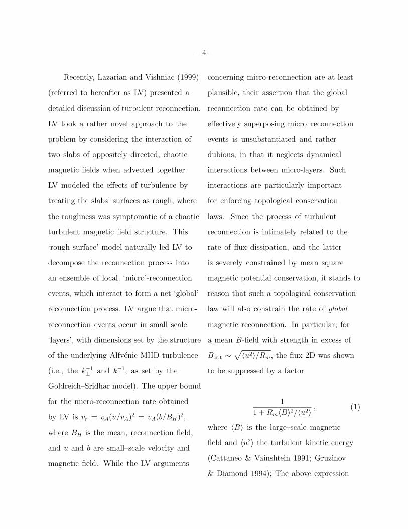
Recently, Lazarian and Vishniac (1999)
(referred to hereafter as LV) presented a
detailed discussion of turbulent reconnection.
LV took a rather novel approach to the
problem by considering the interaction of
two slabs of oppositely directed, chaotic
magnetic fields when advected together.
LV modeled the effects of turbulence by
treating the slabs’ surfaces as rough, where
the roughness was symptomatic of a chaotic
turbulent magnetic field structure. This
‘rough surface’ model naturally led LV to
decompose the reconnection process into
an ensemble of local, ‘micro’-reconnection
events, which interact to form a net ‘global’
reconnection process. LV argue that micro-
reconnection events occur in small scale
‘layers’, with dimensions set by the structure
of the underlying Alfvenic MHD turbulence
(i.e., the k−1⊥ and k−1
‖ , as set by the
Goldreich–Sridhar model). The upper bound
for the micro-reconnection rate obtained
by LV is vr = vA(u/vA)2 = vA(b/BH)
2,
where BH is the mean, reconnection field,
and u and b are small–scale velocity and
magnetic field. While the LV arguments
concerning micro-reconnection are at least
plausible, their assertion that the global
reconnection rate can be obtained by
effectively superposing micro–reconnection
events is unsubstantiated and rather
dubious, in that it neglects dynamical
interactions between micro-layers. Such
interactions are particularly important
for enforcing topological conservation
laws. Since the process of turbulent
reconnection is intimately related to the
rate of flux dissipation, and the latter
is severely constrained by mean square
magnetic potential conservation, it stands to
reason that such a topological conservation
law will also constrain the rate of global
magnetic reconnection. In particular, for
a mean B-field with strength in excess of
Bcrit ∼√
〈u2〉/Rm, the flux 2D was shown
to be suppressed by a factor
1
1 +Rm〈B〉2/〈u2〉 , (1)
where 〈B〉 is the large–scale magnetic
field and 〈u2〉 the turbulent kinetic energy
(Cattaneo & Vainshtein 1991; Gruzinov
& Diamond 1994); The above expression

– 5 –
implies that even a weak magnetic field
(i.e, one far below the equipartition value
〈b2〉 ∼ 〈u2〉) is potentially important. The
origin of this suppression is ultimately
linked to the conservation of mean square
potential (see Das & Diamond 2000 for flux
diffusion in EMHD). Hence, it is natural to
investigate the effect of such constraints on
reconnection, as well.
In turbulent reconnection, fluctuating
magnetic fields are dynamically coupled to a
large–scale magnetic field so that a similar
suppression of energy transfer is expected to
occur. In other words, fluctuating magnetic
fields will inhibit the energy transfer from
large–scale to small–scale magnetic fields
(responsible for turbulent diffusion), even
when the latter is far below equipartition
value. This link between small and large
scale magnetic field dynamics is indeed the
very feature that is missing in LV, where
a global reconnection rate is considered
to be a simple sum of local reconnection
events, without depending on either 〈B〉 or
Rm. That is, even if one local reconnection
event may proceeds fast, the energy transfer
from large–scale to small–scale is suppressed
inversely with Rm, preventing many local
reconnection events for a large Rm and fixed
large–scale field strength. Thus, the global
reconnection rate is very likely to be reduced
for large Rm.
The purpose of this paper is to
determine the global reconnection rate
by treating the dynamics of large and
small–scale magnetic fields in a consistent
way. The key idea is to compute the effective
dissipation rate of a large–scale magnetic
field (turbulent diffusivity) by taking into
account small–scale field backreaction and
then to use Sweek-Parker type balance
relations to obtain the global reconnection
rate. Since magnetic fields across current
sheets are not always strictly antiparallel
in real systems, we assume that only one
component of the magnetic field (e.g.,
poloidal or horizontal field) changes its
sign across the current sheet (see Fig. 2).
The other component (e.g., axial field) is
assumed to be very strong compared to
the poloidal component. A strong axial
magnetic field avoids the null point problem
– 6 –
inherent in SP slab model, justifying the
assumption of incompressibility of the
flow in the poloidal (horizontal) plane.
Such a magnetic configuration is ideal for
the application of so–called 3D reduced
MHD (3D RMHD) (Strauss 1976). In
3D RMHD, the conservation of the mean
square potential is linearly broken due to
the propagation of Alfven waves along an
axial field, but preserved by the nonlinearity.
As we shall show later, the latter effect
introduces additional suppression in the
effective dissipation of a large–scale magnetic
field compared to 2D MHD. We also discuss
the 2D MHD case which can be recovered
from our results simply by taking the limit
B0 → 0, where B0 is a axial magnetic field.
To be able to obtain analytic results,
we adopt the following two methods. The
first is a quasi–linear closure together using
τ approximation by assuming the same
correlation time for fluctuating velocity and
magnetic fields employing unity magnetic
Prandtl number. The second is an eddy-
damped fluid model, based on large viscosity
(Kim 1999), which may have relevance in
Galaxy where ν ≫ η. In this model, the
nonlinear backreaction can be incorporated
consistently, without having to invoking the
presence of fully developed MHD turbulence,
or assumptions such as a quasi–linear closure
or τ approximation. In both models, the
isotropy and homogeneity of turbulence is
assumed in the horizontal (poloidal) plane
since the reduction in effective dissipation
of a large–scale poloidal magnetic field
is likely to occur when its strength is far
below the equipartition value. The effect
of hyper-resistivity is incorporated in our
analysis. This can potentially accelerate the
dissipation of a large–scale poloidal magnetic
field.
The paper is organized in the following
way. In §2, we set up our problem in
3D RMHD and provide the quasi–linear
closure using τ approximation where the
flux is estimated in a stationary case.
Section 3 contains a similar analysis for
an eddy-damped fluid model. The global
reconnection rate for both models is
presented in §4. Our main conclusion and
discussion is found in §5.

– 7 –
2. QUASI–LINEAR MEAN FIELD
EQUATIONS
We assume that a strong constant
axial magnetic field B0 is aligned in the z
direction and that a poloidal (horizontal)
magnetic field BH lies in the horizontal x-y
plane, as shown in Fig. 2. The subscript
H denotes horizontal direction. The
total magnetic field is then expressed as
B = B0z +BH = B0z +∇×ψz, in terms of
a parallel component of the vector potential
ψ (i.e., BH = ∇×ψz). According to the
RMHD ordering, the flow in the horizontal
plane u is incompressible and therefore can
be written using a scalar potential φ as
u = ∇×φz. Then, the equations governing
3D RMHD are (see Strauss 1976):
∂tψ + u · ∇ψ = η∇2ψ +B0∂zψ , (2)
∂t∇2φ+ u · ∇∇2φ = ν∇2∇2φ+B · ∇∇2ψ ,(3)
where η and ν are Ohmic diffusivity and
viscosity, respectively. For the quasi–linear
closure, unity magnetic Prandtl number
(η = ν) will implicitly be assumed. In
comparison with 2D MHD, the equation for
the vector potential contains an additional
term B0∂zφ, which reflects the propagation
of Alfven wave along the axial magnetic
field B0z. Due to this additional term,
the conservation of the mean square
potential is broken in 3D RMHD, albeit
only linearly. In other words, the nonlinear
term in equation (2) conserves 〈ψ2〉 since
〈u · ∇ψ2〉 = ∇ · 〈uψ2〉 = 0, assuming that
boundary terms vanish (cf. Blackman &
Field 2000). Similarly, the momentum
equation contains an additional term
B0∂z∇2ψ. These additional terms are
proportional to the wavenumber kz along
B0z. Thus, the 2D case can be recovered
by taking kz → 0 or B0 → 0. Note that
due to a strong axial field B0z, the vertical
wavenumber kz is much smaller than
horizontal wavenumber kH = kxx + kyz;
specifically, the 3D RMHD ordering implies
that kz/kH ∼ BH/B0 ∼ ǫ ≪ 1.
We envisage a situation where large–
scale magnetic fields with a horizontal
component BH = 〈BH〉 = ∇×〈ψ〉z are
embedded in a turbulent background.
The turbulence can be generated by an
external forcing, for instance. The horizontal

– 8 –
component of a large–scale magnetic field
〈BH〉 flows to form a current sheet of
thickness ∆ in the horizontal plane, so 〈BH〉
changes sign across the current sheet. As
reconnection proceeds, small–scale flows as
well as magnetic fields are generated within
the current sheet. It is reasonable to model
the physical processes within a current sheet
as well as the background turbulence by an
(approximately) isotropic and homogeneous
turbulence with fluctuating velocity u
and magnetic field b = ∇×ψ′z. Here the
assumption of isotropy is justified since
〈BH〉2 ≪ 〈u2〉, i.e. the reconnecting field is
taken to be weak.
Outside the reconnection region, there
are large–scale inflow and outflow in addition
to the background turbulence. Thus, to
obtain SP-like balance relations, small–scale
flow as well as large–scale flow should be
incorporated. However, since small–scale
velocity is assumed to be homogeneous and
isotropic, there is no net contribution from
the fluctuating velocity to mass continuity.
Effectively, the small–scale velocity does not
appear in the momentum balance either.
However, Ohm’s law (magnetic energy
balance) now contains an additional term
due to the correlation between fluctuating
fields 〈u×b〉, leading to turbulent diffusitivy
(effective dissipation rate), which then
effectively changes the Ohmic diffusivity to
the sum of Ohmic diffusivity and turbulent
diffusivity inside current sheet. Therefore,
similar balance relations to the original
SP hold in our case as long as the Ohmic
diffusivity is replaced by the total diffusivity.
To recapitulate, homogeneous and
isotropic turbulence is assumed to be present
with magnetic fields BH = 〈BH〉 + b
(〈b〉 = 0) and small–scale velocity u
(〈u〉 = 〈φ〉 = 0). Once the effective
dissipation rate of 〈BH〉 within the
reconnection zone is computed, it will be
used to determine the reconnection velocity
vr through SP balance relations by using the
total diffusivity in place of Ohmic diffusivity.
2.1. Mean Field Equation
The evolution equation for ψ is obtained
by taking the average of the above equation

– 9 –
as:
∂t〈ψ〉+ 〈u · ∇ψ′〉 = η∇2〈ψ〉 . (4)
Note that although equation (4) does not
exhibit an explicit dependence on B0, it does
depend on B0 through the flux Γi ≡ 〈uiψ′〉.
To compute the flux Γi, we first do a
quasi–linear closure of 〈u · ∇ψ′〉.
The effect of the backreaction can be
incorporated in the flux Γi by considering
the change in flux Γi to be due to the change
in the velocity as well as the fluctuating
magnetic field. That is, we can rewrite the
flux as
Γi = ǫij3〈∂jφψ′〉 = ǫij3〈∂jφδψ′ − δφ∂jψ′〉 ,(5)
where unity magnetic Prandtl number is
assumed for the equal splitting between
〈∂jφδψ′〉 and 〈δφ∂jψ′〉; the latter essentially
takes the backreaction to be as important as
the kinematic contribution.
2.2. Fluctuations
¿From equations (2) and (3), we can
write the equation for the fluctuations in the
following form.
(∂t + u · ∇)ψ′ − 〈u · ∇ψ′〉 = −u · ∇〈ψ〉+ η∇2ψ′ +B0∂zψ′ ,
(∂t + u · ∇)∇2φ− 〈u · ∇∇2φ〉 = ν∇2∇2φ+B0∂z∇2ψ′ + 〈BH〉 · ∇H∇2ψ′ + b · ∇H∇2〈ψ〉 .
Here we have assumed that there is no
large–scale flow in the current sheet. To
estimate δφ and δψ′ in equation (5),
we introduce a correlation time τ that
represents the overall effect of inertial and
advection terms on the left hand side of the
above equations. That is, we approximate
(∂t + u · ∇)ψ′ − 〈u · ∇ψ′〉 ≡ τ−1ψ′, and
(∂t + u · ∇)∇2φ − 〈u · ∇∇2φ〉 ≡ τ−1∇2φ,
where the same correlation time τ is assumed
for both the fluctuating flow and magnetic
field due to unity magnetic Prandtl number.
Then, δφ and δψ′ in equation (5) can be
estimated from the above equations as
follows:
δψ′ = τ [B0∂zφ′ − ǫij3∂jφ
′∂i〈ψ〉] , (6)
δ∇2φ = τ[
B0∂z∇2ψ′ + ǫij3∂j〈ψ〉∂i∇2ψ′ + ǫij3∂jψ′∂i∇2〈ψ〉
]
.(7)
In Fourier space, the above equations take
the following form:
δψ′(k) = τ [B0ikzφ(k) + ǫij3
∫
d3k′k′jφ(k′)(k − k′)i〈ψ(k− k′)〉] , (8)
δφ(k) = iτ[
B0kzψ′(k) + iǫij3
1
k2
∫
d3k′[
(k − k′)jk′ik
′2 + k′j(k − k′)j(k− k′)2]
ψ′(k′)

– 10 –
×〈ψ(k− k′)〉]
. (9)
Note that in principle, the correlation time
can be a function of the spatial scale, or the
wavenumber, i.e., τ = τk. Nevertheless, for
the notational simplicity, we have taken τ to
be a constant by assuming that the variation
of τk in k is small or that the small–scale
fields possess a characteristic scale with
a small spread in k. Our final result will
not fundamentally change when the scale
dependence of τ is incorporated.
The flux Γi can readily be computed
once the statistics of small–scale magnetic
field and the velocity are specified. As
mentioned earlier, the statistics of both
fluctuations are assumed to be homogeneous
and isotropic in the x-y plane. We further
assume that the former is homogeneous and
reflectionally symmetric in the z direction
with no cross correlation between horizontal
and vertical components, thereby eliminating
a helicity term. The absence of helicity terms
rules out a possibility of a mean field dynamo
in our model. Note that due to the presence
of a strong axial field B0z, the correlation
functions cannot be everywhere isotropic.
Specifically, the correlation functions at
equal time t are taken to have the form:
〈ψ′(k1, t)ψ′(k2, t)〉 = δ(k1 − k2)ψ(k1H , k1z) ,(10)
〈φ(k1, t)φ(k2, t)〉 = δ(k1 − k2)φ(k1H , k1z) ,(11)
where ψ(k1H , k1z) and φ(k1H , k1z) are the
power spectra of ψ′ and φ, respectively.
These depend on only the magnitude of
horizontal wavenumber k1H =√
k21x + k21y
and vertical wavenumber k1z. Finally, we
assume that 〈φψ′〉 = 0, which can be shown
to be equivalent to excluding the generation
of a large–scale flow by the Lorentz force.
Straightforward but tedious algebra
using equations (8)–(11) in equation (5)
leads to the following expression for the flux
(the details are given in Appendix A):
Γi = −τ2
[
(〈u2〉 − 〈b2〉)∂i〈ψ〉 − 〈ψ′2〉∂i∇2〈ψ〉]
,(12)
where 〈u2〉 =∫
d3kk2φ(k), 〈ψ′2〉 =∫
d3kψ(k), and 〈b2〉 =∫
d3kk2ψ(k). The
first term on the right hand side of equation
(12) represents the kinematic turbulent
diffusion by fluid advection of the flux;
the second represents the flux coalescence

– 11 –
due to the backreaction of small–scale
magnetic fields with the (negative) diffusion
coefficient proportional to the small–scale
magnetic energy 〈b2〉. The third term is the
hyper-resistivity, reflecting the contribution
to Γi due to the gradient of a large–scale
current 〈J〉 = −∇2〈ψ〉. (Jz = ∇×BH).
Note that the value of hyper-resistivity,
being proportional to mean square potential,
is related to the small–scale magnetic
energy as 〈ψ′2〉 = L2bH〈b2〉, where LbH is
the typical horizontal scale of b. Thus, the
negative magnetic diffusion (second) term
and hyper-resistivity (third) term are closely
linked through the small–scale magnetic
energy 〈b2〉. Indeed, the negative diffusivity
and hyper-resistivity together conserve total
〈ψ′2〉, while shuffling the 〈ψ′2〉 spectrum
toward large scales. We now put equation
(12) in the following form:
〈b2〉 =2Γi/τ + 〈u2〉∂i〈ψ〉∂i〈ψ〉+ L2
bH∂i∇2〈ψ〉 , (13)
where no summation over the index i occurs.
2.3. Stationary Case: ∂t〈ψ′2〉 = 0
To compute the flux Γi, we need an
additional relation between 〈b2〉 and Γi
besides equation (13). This can be attained
by imposing a stationarity condition on
〈ψ′2〉. The stationarity of fluctuations is
achieved in a situation where the energy
transfer from large–scale fields balances
the dissipation of fluctuations locally, as
is usually the case in the presence of an
external forcing and dissipation. To obtain
this relation, we multiply the equation for ψ′
by ψ′ and then take the average
1
2∂t〈ψ′2〉+ ǫij3〈∂jφψ′〉∂i〈ψ〉 = −η〈(∂iψ′)2〉+B0〈ψ′∂zφ〉 .(14)
Here, the integration by parts was used
assuming that there are no boundary
terms. We note that either when the
stationarity condition is not satisfied or
when boundary terms do not vanish, there
will be a correction to our results (Blackman
& Field 2000). When 〈ψ′2〉 is stationary, the
first term on the left hand side of equation
(14) vanishes, simplifying the equation that
relates 〈b2〉 to Γi = 〈uiψ′〉 = ǫij3〈∂iφψ′〉 to

– 12 –
the form:
〈(∂iψ′)2〉 = 〈b2〉 = 1
η[−Γi∂i〈ψ〉+B0〈ψ′∂zφ〉] .(15)
Note that in 2D MHD (B0 = 0), the flux is
proportional to η〈b2〉. This balance reflects
the conservation of 〈ψ2〉, which is damped
only by Ohmic diffusion. The second term
on the right hand side of equation (15) can
be evaluated in a similar way as for Γi, i.e.,
by writing
〈ψ′∂zφ〉 = 〈δψ′∂zφ− ∂zψ′δφ〉 , (16)
and then by using equations (8)–(11).
Omitting the intermediate steps (see
Appendix A for details), the final result is
〈ψ′∂zφ〉 = τB0[ξv〈u2〉 − ξb〈b2〉] . (17)
Here
ξv ≡∫
d3kk2zφ(k)/
∫
d3kk2Hφ(k) , (18)
ξb ≡∫
d3kk2zψ(k)/
∫
d3kk2Hψ(k) ,(19)
and k2H = k2x + k2y. If the characteristic
horizontal and vertical scales of u are LvH
and Lvz, and if those of b are LbH and Lbz ,
then ξv and ξb can be expressed in terms of
these characteristic scales as:
ξv =L2vH
L2vz
, ξb =L2bH
L2bz
. (20)
Insertion of equation (17) into (15) gives us
〈b2〉 =1
η
[
−Γi∂i〈ψ〉+ τξvB20〈u2〉
]
/
(
1 +τξbηB2
0
)
.(21)
Thus, from equations (13) and (21), we
obtain
Γi = −τ2〈u2〉
1 + τηB2
0(ξb − ξv) +τL2
bH
ηξvB
20 |∂i∇
2〈ψ〉∂i〈ψ〉
|
1 + τη
[
12〈BH〉2 + ξbB
20 −
L2
bH
2〈J〉2
] ∂i〈ψ〉 ,(22)
where Jz = ∇×BH and the integration
by part is used to express ∂i〈ψ〉∂i∇2〈ψ〉 =
−(∇2〈ψ〉)2 = −〈J〉2 < 0. Note the last
term in the numerator and denominator
in equation (22) comes from the hyper-
resistivity. Equation (22) is the flux in
3D RMHD, which generalizes the 2D
MHD result (Cattaneo & Vainshtein 1991;
Gruzinov & Diamond 1994). Several aspects
of this result are of interest. First, in the
limit as B0 → 0 and 〈BH〉 → 0 (〈J〉 → 0),
the flux reduces to the kinematic value
Γi = −ηk∂i〈ψ〉, with the kinematic turbulent
diffusivity ηk = τ〈u2〉/2. This corresponds to
the 2D hydrodynamic result where the effect
of the Lorentz force is neglected. The full 2D
MHD result can be obtained by taking the
limit B0 → 0 in equation (22), which will
reproduce equation (1). This agrees with

– 13 –
the well–known result on the suppression of
flux diffusion in 2D (Cattaneo & Vainshtein
1991; Gruzinov & Diamond 1994).
Another interesting case may be
the limit 〈BH〉 → 0. In fact, this limit
can be shown to be consistent with the
ordering of 3D RMHD as follows. First,
note that 3D RMHD ordering (kz/kH ∼
BH/B0 ∼ ǫ < 1) requires ξbB20 ∼ 〈B2
H〉.
Since 〈BH〉2 ≪ 〈B2H〉 ∼ 〈b2〉, we expect
that ξbB20 ∼ 〈b2〉 ≫ 〈BH〉2. Furthermore,
L2bH〈J〉2 ∼ (LbH/LBH)
2〈BH〉2 < 〈BH〉2,
where LBH is the characteristic scale of
〈BH〉. Thus, the dominant term in the
square brackets in the denominator of
equation (22) is ξbB20 ∼ 〈b2〉. That is, the
effect of B0 seems to be stronger than that
of 〈BH〉 in 3D RMHD.
Finally, to determine whether B0
enhances the flux or not, we note that
ξv − ξb in equation (22) can be taken to
be zero, since the scales for b and u are
likely to be comparable in this model, which
employs unity magnetic Prandtl number.
Then, we estimate the last term in the
numerator, due to hyper–resistivity, to be
τ〈b2〉L2bH/(ηL
2BH) ∼ (LbH/LBH)
2Rm where
ξbB20 ∼ 〈b2〉 and 〈b2〉 ∼ 〈u2〉 are used. If
(LbH/LBH)2 ∼ R−1
m , this term will be of
order unity. Note Rm = ul/η is the magnetic
Reynolds number, with u and l being the
characteristic amplitude and length scale
of the velocity. Therefore, equation (22)
indicates that the flux is reduced on account
of the strong axial magnetic field B0 as well
as the horizontal reconnecting field 〈BH〉.
The above analyses will be used in §4.1 in
order to estimate the effective dissipation
and global reconnection rate.
3. EDDY-DAMPED FLUID MODEL
The analysis performed in the previous
section introduced an arbitrary correlation
time τ that is assumed to be the same for
both small–scale velocity and small–scale
magnetic fields. Moreover, the quasi–linear
closure is valid strictly only when the
small–scale fields remain weaker than the
large–scale fields. In order to compensate
for these shortcomings, we now consider an

– 14 –
eddy-damped fluid model which is based a
large viscosity (Kim 1999). In this model, the
fluid motion is self–consistently generated by
a forcing with a prescribed statistics as well
as by the Lorentz force, without having to
assume the presence of fully developed MHD
turbulence, to invoke a quasi–linear closure,
or to introduce an arbitrary correlation
time for the fluctuating fields. This is the
simplest model within which the nonlinear
effect of the back–reaction can rigorously
be treated. Even though this model has
limited applicability to a system with a large
viscosity, it could be quite relevant to small
scale fields in Galaxy where ν ≫ η. As shall
be shown later, this model gives rise to an
effective correlation time for the fluctuating
magnetic fields that is given by the viscous
time τν = l2bH/ν, where lbH is the typical
scale of the magnetic fluctuations in the
horizontal plane (cf eqs. [22] and [32]). Thus,
in comparison with the τ approximation in
the previous section, this model is equivalent
to replacing τ by τν despite the fact that
some of detailed results for the two models
are not the same.
3.1. Splitting of Velocity
In a high viscosity limit with the fluid
kinetic Reynolds number Re = ul/ν < 1,
the nonlinear advection term as well as
inertial term in the momentum equation
can be neglected. Then, the linearity of the
remaining terms in the momentum equation
enables us to split the velocity into two
components; the first — random velocity —
is solely governed by the random forcing, and
the second — induced velocity — is governed
by the Lorentz force only. Specifically, we
express the total velocity u as u = v + v′,
where v and v′ are the random and induced
velocity, respectively, and introduce velocity
potential φ0 and φI as v = ∇×φ0z and
v′ = ∇×φI z. Then, the equations for these
potentials are:
0 = ν∇2φ0 + F , (23)
0 = ν∇2φI +B · ∇∇2ψ , (24)
where the nonlinear advection term as
well as the inertial term is neglected since
Re < 1 is assumed. In equation (23),
F is a prescribed forcing with known
statistics. Instead of solving equation (23)

– 15 –
for φ0, we can equivalently prescribe the
statistics of the random velocity φ0 (or v).
Therefore, we assume that the statistics of
random component satisfies homogeneity
and isotropy in the horizontal plane and
homogeneity and reflectional symmetry in
the z direction, respectively. Furthermore,
we assume that it is delta correlated in time.
The correlation function is then given by:
〈φ0(k1, t1)φ0(k2, t2)〉 = δ(k1 − k2)δ(t1 − t2)φ0(k1H , k1z) ,(25)
where φ0(k1H , k1z) is the power spectrum
of φ0. Note that τ0〈φ20〉 =
∫
d3kφ(k) and
τ0〈v2〉 =∫
d3kk2φ(k), where τ0 is the
correlation time of v that is assumed to be
short.
On the other hand, the induced velocity
can be constructed by solving equation (24)
for φI in terms of B. This can easily be done
in Fourier space as:
φI(k) =i
νk2k2H
[
B0k2k2H + iǫij3
∫
d3k′(k − k′)jk′Hik
′2Hψ(k− k′)ψ(k′)
]
,(26)
where BHi(k) = iǫij3kjψ(k) is used. Note
that the ψ in the above equation contains
both mean and fluctuating parts.
3.2. Magnetic Field
Both random and induced velocities
are to be substituted in equation (2) to
solve for the magnetic field. Notice that
equation (2) then has a cubic nonlinearity,
since the induced velocity is quadratic in B.
We again assume that the magnetic field in
the horizontal plane consists of mean and
fluctuating components, i.e., ψ = 〈ψ〉 + ψ′
and that the fluctuation is homogeneous and
isotropic in the x-y plane and homogeneous
and reflectionally symmetric in the z
direction, satisfying the same correlation
function as equation (10).
To obtain equations for 〈ψ〉 and 〈ψ2〉, we
utilize the delta–correlation in time of v and
iterate equation (2) for small time intervals
δt. Specifically, we use 〈vi(t1)B(t)j〉 = 0
for t1 > t and v ∼ O((δt)−1/2) since
〈vi(t1)vj(t2)〉 ∝ δ(t1 − t2) ∼ 1/δt, where
δt = t1 − t2. Then, for δt ≪ 1, equation (2)
can be iterated up to order O(δt) as:
ψ(t+ δt)
= ψ(t) + δtη∇2ψ(t) +
∫ t+δt
t
dt1 [ǫij3∂jψ(t)∂iφ(t1) +B0∂zψ(t1)]

– 16 –
+1
2ǫij3
∫ t+δt
t
dt1dt2 [ǫlm3∂iφ(t1)∂j [∂mψ(t)∂lφ(t2)] +B0∂iφ(t1)∂jzφ(t2)] +O(δt3/2) ,(27)
where ψ and φ are to be evaluated at the
same spatial position x.
The mean field equation is obtained
by substituting equation (26) in (27), by
taking the average with the help of equations
(10) and (25), and then by taking the limit
δt → 0. The derivation is tedious and is
outlined in Appendix B. Here, we give the
final result
∂t〈ψ〉 = η∇2〈ψ〉+[
τ04〈v2〉 − 1
2νG
]
∇2〈ψ〉 − F
ν∇2∇2〈ψ〉
= (η + ηM)∇2〈ψ〉 − µ∇2∇2〈ψ〉 . (28)
Here τ0 is the short correlation time of
random velocity v and
ηM ≡ τ04〈v2〉 − 1
2νG ≡ ηk −
1
2νG ,
µ ≡ F
ν,
G ≡∫
d3kk2Hk2ψ(k) ≃ 〈ψ′2〉 ≡ κ〈b2〉 ,
F ≡∫
d3kk2Hk
2z
k6ψ(k) ≃ L4
bH
L2bz
G ≡ γG ,
where ηk = τ0〈v2〉/4 is the kinematic
diffusivity; κ ≡ L2bH and γ ≡ L4
bH/L2bz = κξb.
The above equation implies that the flux
Γi = 〈uiψ′〉 is given by
Γi = −ηM∂i〈ψ〉+ µ∂i∇2〈ψ〉 . (29)
Again, the two terms in ηM are due to
the kinematic turbulent diffusivity and
backreaction. Note that the kinematic
diffusivity ηk = τ0〈v2〉/4 now comes only
from the random velocity, with τ0 being
its correlation time that can be prescribed.
The backreaction term is proportional to
〈ψ′2〉, not 〈b2〉 (cf. eq. [11]) and inversely
proportional to the viscosity ν. It is because
the cutoff scale of the magnetic field lη
is smaller than that of the velocity lν in
this model so that for a larger ν, there are
magnetic modes over a larger interval of
scale l between lη and lν (i.e. lη < l < lν)
where the velocity is absent due to viscous
damping. That is, the induced velocity
(Lorentz force) cannot be generated on this
scale (lη < l < lν) due to viscous damping,
thereby weakening the overall effect of
backreaction (see eq. [48]). Now, the last
term in equation (29) is the contribution
from the hyper-resistivity µ. It is interesting
to see that µ is inversely proportional to
L2bz and thus vanishes as Lbz → ∞ (or
γ → 0) which corresponds to the 2D limit.
Therefore, in this eddy-damped fluid model,

– 17 –
the hyper-resistivity term vanishes in two
dimensions. It should be contrasted to the
case considered in the previous section where
the hyper-resistivity, being proportional
〈ψ′2〉, survives in 2D MHD limit (see eq.
[12]).
For use later, we solve equation (29) for
〈b2〉 yielding
〈b2〉 =Γi + ηk∂i〈ψ〉
κ2ν∂i〈ψ〉+ κγ
ν∂i∇2〈ψ〉 , (30)
where again the summation over the index i
is not implied.
3.3. Stationary Case: ∂t〈ψ′2〉 = 0
The additional relation between the flux
Γi and magnetic energy 〈b2〉 is obtained for
the case of stationary 〈ψ′2〉. To derive an
equation for 〈ψ2〉, we multiply equation (27)
by itself, take average, and then take the
limit of δt → 0. After considerable algebra
(see Appendix B), we obtain the following
equation
∂t〈ψ′2〉+ ∂t〈ψ〉2 − 2η[
−〈(∂iψ)2〉+ 〈ψ〉∇2〈ψ〉]
= B20
[
ξv〈v2〉 −2
νG
]
,(31)
where
G ≡∫
d3kk2zk2ψ(k) ∼ L2
bz
L2bH
G = ξbG ,
In a stationary case, equations (28), (30),
and (31) lead us to the following expression
for the flux:
Γi = −τ04〈v2〉
1 + κηνB2
0(ξb − ξv) +2κγηνξvB
20
∣
∣
∣
∂i∇2〈ψ〉∂i〈ψ〉
∣
∣
∣
1 + κην
[
ξbB20 +
12〈BH〉2 − γ〈J〉2
] ∂i〈ψ〉 ,(32)
where Jz = ∇×BH, and ∂i∇2〈ψ〉∂i〈ψ〉 =
−(∇2〈ψ〉)2 = −〈J〉2 < 0 is used. When the
characteristic scales of fluctuating velocity
and magnetic field are comparable, or when
only the ratios of vertical to horizontal scales
of the fluctuating velocity and magnetic
fields are comparable, ξv can be taken to be
equal to ξb, simplifying the above expression.
It is worth considering a few interesting
limits of equation (32). First, in the limit
B0 → 0 and BH → 0, equation (32) again
recovers the 2D hydrodynamic result with
the kinematic diffusivity ηk = τ0〈v2〉/4.
The limit B0 → 0 leads to 2D MHD case
where the suppression of the turbulent
diffusion arises from 〈BH〉. In 3D RMHD,
the dominant suppression in the flux comes
from B0 when ξv = ξb, as discussed in §2.3.
We note that the last term in the
numerator and denominator is due to
the hyper-resistivity, which comes with a

– 18 –
multiplicative factor γ = L2bH/L
2bz ≪ 1.
Therefore, the effect of hyper-resistivity
can be neglected as compared to other
terms in equation (32). Since γ → 0 in
2D MHD, there is no contribution from
the hyper-resistivity to the flux in 2D in
this model. The estimate of the effective
dissipation in this model is provided in §4.2.
It is very interesting to compare
equation (32) with (22). We recall that
in order to derive equation (22), the same
correlation time τ was assumed for both
fluctuating magnetic field and velocity, which
appears in front of the mean magnetic fields
B0 and 〈ψ〉 in equation (22). In contrast, τ0
in equation (32) is the correlation time of
the random component of the velocity, which
can be arbitrarily prescribed. Moreover, τ
in front of mean magnetic fields in equation
(22) is now replaced by viscous time scale
τν = κ/ν = L2bH/ν in equation (32). The
latter represents the viscous time scale across
the typical horizontal scale of fluctuating
magnetic fields. Thus, as noted at the
beginning of this section, this viscous time τν
replaces τ in the quasi–linear closure, which
was assumed to be a parameter.
4. RECONNECTION RATE
In previous sections, the flux Γi was
derived by using a quasi–linear closure and
an eddy-damped fluid model. Assuming the
flux Γi has a form proportional to ∂i〈ψ〉
in both cases (see eqs. [22] and [32]), it
can be expressed in terms of the effective
dissipation rate (or, turbulent diffusivity)
ηeff as follows:
Γi = −ηeff∂i〈ψ〉 . (33)
Upon using equation (33), the mean field
equation (4) then becomes
∂t〈ψ〉 = (η + ηeff)∇2〈ψ〉 ≡ ηT∇2〈ψ〉 .(34)
where ηT ≡ η + ηeff is the total dissipation
rate of the mean field. The effective
dissipation rate is the quantity that
represents the overall decay rate of a large–
scale magnetic field due to both small–scale
motions and magnetic fluctuations. That
is, the dynamical system consisting of
both small and large scale fields can be
represented by the evolution of a large–scale

– 19 –
field only when the effect of small–scale fields
is absorbed in this turbulent coefficient.
In order to determine a global
reconnection rate, we now invoke the original
SP type balance equations and use the
total dissipation rate in place of the Ohmic
diffusivity (see §2):
vr =vA
√
vAL/ηT. (35)
Note that we have neglected a multiplicative
correction factor to the reconnection
rate in the eddy-damped model since its
dependence on ν is weak with 1/4 power
(for instance, see, Biskamp 1993). In the
following subsections, we assume ξv = ξb
for simplicity and estimate the reconnection
rate via equation (35). Then, we briefly
comment on the implication for reconnection
assuming ‘Alfvenic turbulence’, as Lazarian
and Vishniac (1999) did.
4.1. Using the Quasi-linear Result
The effective dissipation rate follows
from equations (22) and (32):
ηeff ≃ τ
2〈u2〉
1 +τL2
bH
ηξvB
20 |∂i∇
2〈ψ〉∂i〈ψ〉
|
1 + τη
[
12〈BH〉2 + ξbB2
0 −L2
bH
2〈J〉2
] ,(36)
after using ξv = ξb. As shown in §2.3, the
dominant term in the square brackets in the
denominator of equation (36) is ξbB20 ∼ 〈b2〉,
and the second term in the numerator is of
order unity if L2BH/L
2bH ∼ Rm. In that case,
ηeff is roughly given by
ηeff ∼ ηk1
1 + τ〈b2〉/η ∼ ηk1
1 + 2Rm〈b2〉/〈u2〉,(37)
where ηk = τ〈u2〉/2 is the kinematic value of
turbulent diffusivity in 2D and Rm = ηk/η.
In contrast to the 2D MHD result (eq. [1])),
the equation (37) reveals that the effective
diffusivity in 3D RMHD is more severely
reduced as 〈b2〉 ≫ 〈BH〉2 (= 〈B〉2). To
determine the leading order contribution in
equation (37), we need to estimate 〈b2〉. To
do so, we substitute equations (33) and (37)
in (13) and use LbH < LBH to obtain:
〈b2〉 ∼ 〈u2〉 − η
τ∼ 〈u2〉
[
1− 1
2Rm
]
,(38)
where Rm = ηk/η = τ〈u2〉/2η is used.
We note that 〈b2〉 > 0 is guaranteed since

– 20 –
〈b2〉 > 〈BH〉2 (implying Rm > 1) was
assumed to derive the above equation. Thus,
τ〈b2〉η
∼ 2Rm − 1 .
That is, for Rm ≫ 1, τ〈b2〉/η ≫ 1. Insertion
of the above equation in (37) then gives us
ηeff ∼ ηk1
2Rm∼ η
2. (39)
In other words, to leading order, the effective
dissipation rate is just that given by Ohmic
diffusivity! Therefore, by inserting equation
(39) into (35) with ηT = η + ηeff , the
reconnection rate is found to have the
original SP scaling with η, i.e.
vr ∼ vA√
vAL/η. (40)
It is interesting to contrast this result
to the 2D case where B0 = 0. In that
case, the dominant term in equation (36)
is 〈BH〉2, with ηeff ∼ ηk〈u2〉/Rm〈BH〉2 ∼
η〈u2〉/〈BH〉2 ∼ ηu2/v2A > η, where u is the
typical velocity. Therefore, in 2D, the global
reconnection rate becomes
vr ∼ vA√
vAL/η
u
vA, (41)
which is larger than SP by a factor of
magnetic Mach number MA = u/vA. Note
that the reduction in the effective dissipation
of a large–scale magnetic field is more severe
in 3D RMHD than in 2D MHD by a factor
of 〈u2〉/〈BH〉2 ∼ 〈u2〉/v2A.
4.2. Using the Eddy-Damped Fluid Model
Result
For an eddy-damped fluid model,
equation (32) yields:
ηeff =τ04〈v2〉
1 + 2κγηνξvB
20
∣
∣
∣
∂i∇2〈ψ〉
∂i〈ψ〉
∣
∣
∣
1 + κην
[
ξbB20 +
12〈BH〉2 − γ〈J〉2
] ,(42)
after assuming ξv = ξb. We recall that the
contribution from the hyper-resistivity comes
with a multiplicative factor γ = L2bH/L
2bz ≪ 1
(vanishing in the 2D MHD limit) and thus
can be neglected as compared to other terms
in equation (42). Then, a similar estimation
as in §4.1 simplifies equation (42) to
ηeff ∼ ηk1
1 + κνη〈b2〉 , (43)
where ηk = τ0〈v2〉/4 is the kinematic value of
the turbulent diffusivity in 2D and κ = L2bH .
To obtain the leading order behavior of
equation (43), we estimate 〈b2〉 with the help
– 21 –
of equation (30) to be
〈b2〉 ∼ ην
κ(2Rm − 1) , (44)
where Rm = ηk/η. By inserting equation
(44) in (43), we obtain
ηeff ∼ ηk2Rm
∼ η
2. (45)
Thus, the reconnection rate is again given by
vr ∼ vA√
vAL/η, (46)
i.e., SP scaling with η persists!
It is interesting to estimate 〈b2〉 in
equation (44) by using
ην
κ= 〈v2〉 η
√
〈v2〉LbHν
√
〈v2〉LbH∼ 〈v2〉 1
RmRe
,(47)
where Re =√
〈v2〉LbH/ν is the fluid
Reynolds number. Thus, equation (44)
becomes
〈b2〉 ∼ 〈v2〉 1
Re
(
2− 1
Rm
)
. (48)
The above equation clearly demonstrates
that 〈b2〉 > 〈v2〉 for our model (Re < 1) when
Rm > 1, as pointed out near the end of §3.2.
Finally, we note that in 2D limit with
B0 → 0, the dominant term in the square
brackets in the denominator of equation (42)
is 〈BH〉2. Thus, ηeff ∼ ηk〈v2〉/ReRm〈BH〉2 ∼
η〈v2〉/Re〈BH〉2 ∼ ηu2/Rev2A > η, where u is
the typical velocity. Therefore, in 2D, the
global reconnection rate becomes
vr ∼ 1√Re
vA√
vAL/η
u
vA, (49)
where u/vA = MA is the magnetic Mach
number. In comparison with equation (41),
the global reconnection rate in this model is
thus larger in the 2D limit (recall Re < 1).
4.3. Alfvenic Turbulence
In Alfvenic turbulence (Goldreich &
Sridhar 1994; 1995; 1997), the equipartition
between 〈b2〉 and 〈u2〉 is assumed from the
start. It is to be contrasted to the present
analysis in which the relation between
〈b2〉 and 〈u2〉 i.e., equations (38) and (49),
follows from the condition of stationarity
of 〈ψ′2〉 in the presence of B0 and 〈BH〉.
As can be seen from equation (38), in the
quasi–linear closure with unity magnetic
Prandtl number, exact equipartition is
possible only for η = 0. In the eddy-damped
fluid model, exact equipartition can never be
satisfied since the assumption Re < 1 implies

– 22 –
〈b2〉 > 〈v2〉 when Rm > 1 (see eq. [48])!
Therefore, in general, stationarity of 〈ψ′2〉
and exact Alfvenic equipartition cannot be
simultaneously achieved. In other words, if
Alfvenic turbulence is assumed, 〈ψ′2〉 cannot
be stationary; if 〈ψ′2〉 is stationary, the
turbulence cannot be in a state of Alfvenic
equipartition.
We easily confirm this in 2D MHD by
quasi–linear closure. The exact equipartition
(〈u2 − b2〉 = 0) implies that the flux Γi in
equation (12) is given by hyper-resistivity
only: Γi = −τ〈ψ′2〉∂i∇2〈ψ〉/2. Then,
if we were to impose the stationarity
of 〈ψ′2〉, equation (15) would indicate
〈ψ′2〉τ∂〈J〉〈BH〉 = η〈b2〉. Thus,
〈BH〉2〈b2〉 Rm ∼
(
lBlb
)2
, (50)
where lB and lb are the characteristic
scales of 〈BH〉 and b, respectively. Since
〈BH〉2/〈u2〉 ∼ 1/Rm (with 〈b2〉 ∼ 〈u2〉) and
(lB/lb)2 ∼ 1/Rm in 2D MHD, the relation
(49) (for stationarity) cannot be satisfied.
5. CONCLUSION AND
DISCUSSIONS
In view of the ubiquity of turbulence
in space and astrophysical plasmas,
magnetic reconnection will likely occur in
an environments with turbulence. On the
other hand, the reconnection itself generates
small–scale fluctuation, feeding back the
turbulence. Thus, it is important to treat
these two processes consistently, accounting
for the back reaction. Although LV argued
that the local reconnection rate can be
fast, they basically neglected the dynamic
coupling between small and large scale fields,
therefore leaving the issue of the global
reconnection rate unresolved. The coupling
between global and local reconnection rates
should be treated self consistently. The aim
of the present work was to shed some light
on this issue by taking the simplest approach
that is analytically tractable.
Our main strategy was to self–
consistently compute the effective dissipation
rate of a large–scale magnetic field within the
current sheet by using stationarity of 〈ψ′2〉

– 23 –
and then use the effective dissipation rate in
SP type balance relations to obtain the global
reconnection rate. To avoid the null point
problem associated with a 2D slab model,
we considered 3D RMHD, within which
we can solidly justify the incompressibility
of the fluid in the horizontal plane. To
facilitate analysis, two models (methods)
were employed, one being a quasi–linear
closure with τ approximation and the other
eddy-damped fluid model.
The effective dissipation rate ηeff that
we obtained generalizes the 2D MHD result
(Cattaneo & Vainshtein 1991; Gruzinov &
Diamond 1994). The quasi–linear closure
predicted ηeff ∼ ηk/(1 + 2Rm〈b2〉/〈u2〉) ∼
η/2 (see eqs. [37]–[39]). A similar result was
obtained in the eddy-damped fluid model
with ηeff ∼ ηk/(1 + RmRe〈b2〉/〈u2〉) ∼ η/2
(see eqs. [43]–[45] and [47]).
The 2D result can simply be recovered
from our results on the flux by taking
the limit B0 → 0. In that limit,
ηeff ∼ ηk/(1 + Rm〈BH〉2/〈u2〉) according
to the quasi–linear closure, consistent with
previous work. In the eddy-damped fluid
model, ηeff ∼ ηk/(1 +RmRe〈BH〉2/〈u2〉).
Since the effective dissipation rate
ηeff was found to be the same in both
models (in 3D RMHD), the global
reconnection, obtained by invoking SP
balance relations, was also the same with the
value vr ∼ vA/√
vAL/η in both models. This
result indicates that the global reconnection
rate is suppressed for large Rm as an inverse
power of R1/2m such that the original SP
scaling with η persists. Again, this persistent
η scaling results from the reduction in the
effective dissipation rate of a large–scale
magnetic field for large Rm mainly due to a
strong axial magnetic field, with the effective
dissipation rate ηeff ∼ η.
Furthermore, in the 2D limit, the
quasi–linear closure yielded the global
reconnection rate vr ∼ (vA/√
vAL/η)(u/vA),
which is enhanced over SP by a factor of
MA = u/vA (note that MA can be large). In
contrast, the eddy-damped fluid model gave
vr ∼√Re
−1(vA/
√
vAL/η)(u/vA).
The implication of these results for
– 24 –
the LV scenario is that no matter how fast
local reconnection events proceed, there is
not enough energy transfer from large–scale
to small–scale magnetic fields to allow
fast global reconnection. Therefore, global
reconnection cannot be given by a simple
sum of the local reconnection events as
LV suggested. We emphasize again that
the 〈ψ′2〉 balance played the crucial role in
determining the global reconnection rate
consistently. Alternatively, an accurate
calculation of the global reconnection
rates requires that (global) topological
conservation laws be enforced.
The reduction in the effective dissipation
in 2D is closely linked to the conservation
of mean square magnetic potential. In
3D RMHD, the mean square of parallel
component of potential is no longer an
ideal invariant due to the propagation of
Alfven waves along a strong axial magnetic
field. Nevertheless, the conservation of mean
magnetic potential is broken only linearly,
which turned out to introduce additional
suppression factors, as compared to 2D. The
interesting question is then how relevant
these results would be in 3D. The mean
square potential is not an invariant of 3D
MHD. However, its conservation is broken
nonlinearly, unlike 3D RMHD. Therefore,
the effective dissipation in 3D MHD may
be very different from that in 3D RMHD,
with the possibility that the former may not
be reduced, at least, in the weak magnetic
field limit (Gruzinov & Diamond 1994;
Kim 1999). Moreover, in 3D, there is a
possibility of a dynamo, which brings in
an additional transport coefficient (the α
effect) into the problem. Some insights into
the problem of effective dissipation of a
large–scale field in the presence of a dynamo
process might be obtained by considering a
simple extension of the present 3D RMHD
model by allowing a large–scale dynamo
in the horizontal plane. Recall that this
possibility was ruled out in the present
paper by assuming isotropy in the horizontal
plane and reflectional symmetry in the axial
direction, with no helicity term (i.e., no
correlation between horizontal and vertical
component of fluctuations).
Considering some of limitations of

– 25 –
the two models that were analyzed in
the paper, such as the τ approximation,
quasi–linear closure, low kinetic Reynolds
number limit, etc, it will be very interesting
to investigate our predictions via numerical
computation. The stationarity of 〈ψ′2〉
can be maintained as long as there is an
energy source in the system, such as an
external forcing. By incorporating the
proper ordering required for 3D RMHD, one
can measure the decay rate of 〈BH〉 to check
our predictions for ηeff ∼ η (see eqs. [40]
and [46]). Ultimately, a numerical simulation
with a simple reconnection configuration
should be performed to measure a global
reconnection rate as a function of Rm as well
as B0 and 〈BH〉. It will also be interesting
to investigate non–stationary states such as
plasmoid formation (Forbes & Priest 1983;
Priest 1984; Matthaeus & Lamkin 1986).
We thank E. Zweibel for bringing this
problem to our attention and for many
interesting discussions. We also thank E.T.
Vishniac and A.S. Ware for stimulating
conversations. This research was supported
by U.S. DOE FG03-88ER 53275. P.H.
Diamond also acknowledges partial support
from the National Science Foundation
under Grant No. PHY99-07949 to the
Institute for Theoretical Physics at U.C.S.B.,
where part of this work was performed.
E. Kim acknowledges partial support from
HAO/NCAR where part of this work was
completed.
Appendix A
In this appendix, we provide some
of steps leading to equations (12) and
(17). First, to derive equation (12), we let
Γi = Γ(1)i − Γ
(2)i , where Γ
(1)i = ǫij3〈∂jφψ′〉 and
Γ(2)i = ǫij3〈φ∂iψ′〉, and begin with Γ
(1)i .
Γ(1)i = ǫij3〈∂jφψ′〉
= ǫij3
∫
d3k1d3k2ik1j〈φ(k1)δψ
′(k2)〉 exp {i(k1 + k2) · x} .(A.1)
After inserting equation (8) in (A1) and
using equation (11), we can easily obtain
Γ(1)i = −iτǫij3ǫlm3
∫
d3k1d3kk1jkimklφ(k1)〈ψ(k)〉eik·x + τǫij3
∫
d3kk1jk1zB0φ(k1)
= −τ2∂l〈ψ〉δil
∫
d3k1k21φ(k1) = −τ
2〈u2〉∂i〈ψ〉 . (A.2)
where 〈u2〉 =∫
d3k1k21φ(k1). To obtain
the last line in equation (A2), we use the
– 26 –
following relations
∫
d3kkjkmφ(k) =1
2δjm
∫
d3kk2φ(k) ,∫
d3kkjkzφ(k) = 0 , (A.3)
which follows from the isotropy of φ in the
x-y plane, and reflectional symmetry in the
z direction.
The second part, Γ(2)i , is calculated in a
similar way.
Γ(2)i = ǫij3〈φ∂jψ′〉
= ǫij3
∫
d3k1d3k2ik2j〈δφ(k1)ψ
′(k2)〉 exp {i(k1 + k2) · x} .(A.4)
We insert equation (9) in (A4) and use (10)
to obtain
Γ(2)i = iτǫij3
[
−iB0
∫
d3k1k1zk1jψ(k1)
+ǫlm3
∫
d3k2d3keik·x
1
(k + k2)2[
kmk2lk22 + k2mklk
2]
k2jψ(k2)〈ψ(k)〉]
(A.5)
Since 〈ψ〉 has a scale much larger than ψ′,
k2 ≫ k in the second integral on the right
hand side. We thus expand the integrand
of this second term and use the following
isotropy relations:
∫
d3kkjkmψ(k) =1
2δjm
∫
d3kk2ψ(k) ,∫
d3kkikjklkmψ(k) =1
8(δijδlm + δilδjm + δimδjl)
∫
d3kk4ψ(k) ,∫
d3kkikzψ(k) = 0 . (A.6)
A bit of algebra then gives us
Γ(2)i =
τ
2
[
−〈b2〉∂i〈ψ(x)〉 − 〈ψ′2〉∂i∇2〈ψ(x)〉]
.(A.7)
Thus, from equations (A3) and (A7), we
obtain equation (12) in the main text.
Second, to derive equation (17), we
again compute the correlation function
on the right hand side of equation (16)
in Fourier space. The first term can be
rewritten as:
〈δψ′∂zφ〉 =
∫
d3k1d3k2ik1z〈φ(k1)δψ
′(k2)〉 exp {i(k1 + k2) · x} .(A.8)
Then, inserting equation (8) in (A8) and
using equation (11) give us
〈δψ′∂zφ〉 = τ[
∫
d3k1k1zk1zB0φ(k1)− ǫlm3
∫
d3k1d3kk1zkimklφ(k1)〈ψ(k)〉eik·x
]
= τB0
∫
d3k1k21zφ(k1) = τB0ξv〈u2〉 , (A.9)
where the isotropy and equation (18) were
used to obtain the last line. Similarly, the
second term on the right side of equation
(16) is easily calculated (in Fourier space) by
using the isotropy condition. The result is
〈∂zψ′δφ〉 = τB0
∫
d3k1k21zψ(k1) = τB0ξb〈b2〉 .(A.10)
Thus, equations (16), (A9), and (A10) yield
equation (17), in the main text.

– 27 –
Appendix B
In this Appendix, we provide some of
intermediate steps used to obtain equations
(28) and (31). For the mean field equation
(28), we first take the average of equation
(27)
〈ψ(t+ δt)〉 − 〈ψ(t)〉 − δtη∇2〈ψ(t)〉 = I1 + I2 + I3(B.1)
where
I1 =
∫ t+δt
t
dt1 [ǫij3∂jψ(t)∂iφI(t1)] ≃ δtǫij3∂i〈∂jψ(t)φI(t)〉 ≡ δt∂i∆i ,
I2 =
∫ t+δt
t
dt1B0∂z〈ψI(t1)〉 ≃ δtB0∂z〈φI(t)〉 ,
I3 =1
2ǫij3
∫ t+δt
t
dt1dt2〈ǫlm3∂iφ0(t1)[∂jmψ(t)∂lφ0(t2) + ∂mψ(t)∂jlφ(t2)]
+B0∂iφ0(t1)∂jzφ0(t2)〉 , (B.2)
where ∆i ≡ ǫij3〈∂jψ(t)φI(t)〉 and the smooth
variation of the induced velocity φI in time
was used to approximate the time integrals
in I1 and I2. To compute the averages,
it is convenient to express the correlation
function (24) in terms of v in real space as:
〈vi(x, t1)vj(y, t2)〉 = δ(t1 − t2)
[
TL(rH , rz)δij + rH∂TL∂rH
(
δij −rHirHjr2H
)]
,(B.3)
where r ≡ y − x and rH is the hor-
izontal component. Note that the
above relation implies that at r = 0,
〈vi(x, t1)vj(x, t2)〉 = δ(t1 − t2)δijTL(r = 0)
so that TL(0) = τ0〈v2〉/2 = 2ηk. Here
τ0 is the short correlation time of v
and ηk = τ0〈v2〉/4 is the kinematic
diffusivity. 〈vi(x)vj(x)〉 is obviously re-
lated to φ0 by 〈∂iφ0(x, t1)∂lφ0(y, t2)〉 =
δil〈vj(x, t1)vj(y, t2)〉+ 〈vi(x, t1)vl(y, t2)〉. By
using vj = −ǫij3∂iφ0 and 〈φ0(t1)ψ(t)〉 = 0,
I3 is determined to be:
I3 =1
2δtTL(0)∇2〈ψ〉 . (B.4)
I3 represents the kinematic turbulent
diffusivity. Next, to compute I2, we take the
inverse Fourier transform of equation (26)
and then take the average. Upon neglecting
∂z〈ψ〉 ∼ 0, one can easily show that I2 = 0.
Finally, I1 contains the backreaction as well
as hyper-resistivity. To evaluate this term,
we insert equation (26) in ∆i to obtain
∆i = ǫij3〈∂jψ(t)φI(t)〉
= − i
νǫij3ǫlm3
∫
d3k2d3k′eik
′·x 1
(k+ k′)2(kH + k′H)
2ψ(−k)Pjlm〈φ(k′)〉 ,(B.5)
here
Pjlm ≡ −kj[
kmk′lk
′2H + klk
′mk
2H
]
.
For notational convenience, we introduce
q = kH so that q3 = 0. Since the

– 28 –
characteristic scale of 〈ψ〉 is much larger
than that of ψ′, k′ ≪ k in equation (B5).
Thus, we expand the integrand of equation
(B5) to second order in (k′/k) and exploit
the isotropy and homogeneity of ψ′ in the
x − y plane. The latter implies equation
(A5) (recall q = kH) and also the following
relations
∫
d3kqjqlqrkn =
∫
d3kqjqlqrqn ,∫
d3kqjqlkzkz =1
2δjl
∫
d3kq2k2z .(B.6)
Then, a fair amount of algebra reduces
equation (B5) to
∆i = − 1
2ν∂i〈ψ〉
∫
d3kk2Hk2ψ(k)− 1
ν∂i∇2〈ψ〉
∫
d3kk2Hk
2z
k6ψ(k)
= − G
2ν∂i〈ψ〉 −
F
ν∂i∇2〈ψ〉 . (B.7)
Note that there is no contribution from the
first order term. By inserting equation (B7)
into (B1), by dividing both sides by δt, and
then by taking the limit of δt→ 0, we obtain
equation (28).
Next, to derive equation (31), we
multiply equation (27) by ψ and then take
average to obtain the following equation:
〈ψ2(t+ δt)〉 − 〈ψ2(t)〉 − 2ηδt〈ψ(t)∇2ψ(t)〉 = J1 + J2 + 2J3 ,(B.8)
where
J1 ≡∫ t+δt
t
dt1dt2
{
ǫij3ǫlm3〈∂jψ(t)∂m(t)∂iφI(t1)∂lφI(t2)〉+ 2B0ǫij3〈∂jψ(t)∂iφI(t1)∂xφI(t2)〉}
,
J2 = ǫij3
∫ t+δt
t
dt1dt2〈ψ(t) [∂iφ0(t1)ǫlm3∂j [∂mψ(t)∂lφ0(t2)] +B0∂iφ0(t1)∂jzφ0(t2)] 〉 ,
J3 =
∫ t+δt
t
dt1〈ψ(t) [ǫij3∂jψ(t)∂iφI(t1) +B0∂zφI(t1)] 〉 ≡ δt(J31 + J32) , (B.9)
where J31 ≡ ǫij3〈ψ(t)∂jψ(t)∂iφI(t)〉 and
J32 ≡ B0〈ψ(t)∂zφI(t)〉.
First, J1 can easily be computed by
using the correlation functions as
J1 = δt
[
TL(0)[
〈b2〉+ 〈BH〉2]
−B20
∫
d3k2zφ(k)
]
.(B.10)
Next, J2 can be computed upon substituting
equation (26) and then splitting average by
using 〈ψ(t)φ(t1)〉 = 0, with the result
J2 = δtTL(0)[
−〈b2〉+ 〈ψ〉∇2〈ψ〉]
.(B.11)
For J3, one can first show J31 = 0 due to
isotropy. To compute J32, we substitute
equation (26) and use 〈φI〉 = 0 to obtain
J32 = −B0
∫
d3k1d3k exp {i(k1 + k2) · x}
kzνk2Hk
2
×〈ψ′(k1)
[
B0kzk2Hψ
′(k) + iǫij3
∫
d3k′ψ(k− k′)(k − k′)jk′ik
′2Hψ(k
′)
]
〉
= −B0
ν
[
B0
∫
d3k1k21zk21ψ(k1)
+iǫij3
∫
d3kd3k1 exp {i(k1 + k2) · x}kzk2Hk
2Qijψ(k1)〈ψ(k+ k1)〉
]
(B.12)

– 29 –
where Qij ≡ −k1j(k + k1)i(kH + k1H)2 −
k1i(k + k1)jk21H . By using the definition
of G (see immediately after eq. [31]) and
ǫij3Qij = −ǫij3(k2H +2kH ·kH)kik1j, equation
(B12) becomes
J32 = −B0
ν
[
B0G− iǫij3
∫
d3k′d3keik′·x kzk2Hk
2
[
k2H + 2kl(k′ − k)l
]
ki(k′ − k)jψ(−k + k′)〈ψ(k′)〉
]
= −B0
ν
[
B0G− ǫij3∂jd3k′
∫
d3keik′·xkzki
k2
[
−1 +2klk
′l
k2H
]
ψ(−k + k′)〈ψ(k′)〉]
. (B.13)
Now, since k′ ≪ k, we expand the integrand
of equation (B13) to second order in k′/k, in
order to show that there is no contribution
from the second term in equation (B13)
(to this order). Therefore, J32 = −B20G/ν.
Inserting J1, J2, and J3 in equation (B8),
dividing by δt, and then taking the limit
δt→ 0 finally yields equation (31).

– 30 –
REFERENCES
Blackman, E.G. & Field, G.B. 2000, ApJ,
534, 984
Biskamp, D. 1986, Phys. Fluids, 29, 1520
Biskamp, D. 1993, Nonlinear Magneto-
hydrodynamics (Cambridge:
Cambridge Univ. Press)
Cattaneo, F & Vainshtein, S.I. 1991, ApJ,
376, L21
Das, A & Diamond, P.H. 2000, Phys.
Plasmas, 7, 170
Diamond, P.H., Hazeltine, R D., An, Z.G.,
Carreras, B.A., & Hickes, H.R.
1984, Phys. Fluids, 27, 1449
Kleva, R.G., Drake, J.F., & Waelbroeck,
F.L. 1995, Phys. Plasmas, 2,
23
Forbes, T., & Priest, E. 1983, J. Geophys.
Res., 88, 863
Goldreich, P. & Sridhar, S. 1994, ApJ, 432,
612
Goldreich, P. & Sridhar, S. 1995, ApJ, 438,
763
Goldreich, P. & Sridhar, S. 1997, ApJ, 485,
680
Gruzinov, A.V., & Diamond, P.H. 1994,
Phys. Rev. Lett., 72, 1651
Ji, H., Yamada, S.H., & Kulsrud, R. 1998,
Phys. Rev. Lett., 80, 3256
Kim, E. 1999, Phys. Lett. A, 259, 232
Kulsrud, R.M. 2000, Astro-ph/0007075
Lazarian, A. & Vishniac, E. 1999, ApJ, 517,
700
Matthaeus, W.H. & Lamkin, S.L. 1986,
Phys. Fluids, 29, 2513
Parker, E.N. 1957, J. Geophys. Res. 62, 509
Parker, E.N. 1979, Cosmical magnetic fields
(Oxford: Oxford University
Press)
Petschek, H.E. 1964, Physics of Solar Flares,
AAS-NASA symposium
(NASA SP-5), ed. W.N. Weiss
(Greenbelt, MD:NASA), 425
Priest, E. 1984, in Space and Laboratory
Plasmas, edited by E. Hones,
Jr. (American Geophysics
Union, Washington, DC), p.

– 31 –
63
Strauss, H.R. 1976, Phys. Fluids, 19, 134
Strauss, H.R. 1988, ApJ, 326, 412
Sweet, P.A. 1958, in IAU Symp. 6,
Electromagnetic Phenomena
in Cosmical Plasmas, ed. B.
Lehnert(New York: Cambridge
Univ. Press), 123
Vasyliunas, V. 1975, Rev. Geophys. Space
Phys., 13, 303
Wang, X, Ma, Z. W., & Bhattacharjee A.
1996, Phys. Plasmas, 3, 2129
This manuscript was prepared with the
AAS LATEX macros v5.0.

– 32 –
Fig. 1.— Sweet–Parker 2D slab configura-
tion. ∆ and L are the thickness and length of
the current sheet; ±B are reconnecting mag-
netic fields; vr and v0 are inflow (reconnec-
tion) and outflow velocities.
Fig. 2.— Configuration in 3D RMHD. B0 is
a strong axial magnetic field pointing in the z
direction, and ±BH are reconnecting (large–
scale) magnetic fields in the x-y plane. Panel
(a) shows the projection in the x-y plane, and
Panel (b) in the y-z plane.

∆
L
vr
v 2
o
y
x
-B
B

x
y
z
y
B
B
H
H+
-x
x
B
B
o
o
z
x
B
B
o
o.
x
B
BH
H
(a)
(b)


![· Homer Lopez James Penrose lie Meng Jin Huh Joyce Chan ]uhi Jain ... Stephanie Hadi Stephen Sebastyan Sue Gilchrist IJpasana Saha Young-Eun Russell](https://img.pdfslide.us/doc/110x75/5b7d57807f8b9a10598c5d26/-homer-lopez-james-penrose-lie-meng-jin-huh-joyce-chan-uhi-jain-stephanie.jpg)