Embed Size (px)
Citation preview
Sira Certification Service Unit 6 Hawarden Industrial Park, Hawarden, CH5 3US, United Kingdom
Tel: +44 (0) 1244 670900 Fax: +44 (0) 1244 681330 Email: [email protected] Web: www.csagroupuk.org
Project Number 70108149 C Ellaby Deputy Certification Manager This certificate and its schedules may only be reproduced in its entirety and without change. Page 1 of 10 Form 9400 Issue 4
1 EU-TYPE EXAMINATION CERTIFICATE 2 Equipment intended for use in Potentially Explosive Atmospheres Directive 2014/34/EU 3 Certificate Number: Sira 06ATEX1295X Issue: 8 4 Equipment: Types 753, 755, S753, 710 & 711 Compound Filled Cable Glands 5 Applicant: Hawke International
A Division of Hubbell Limited A Member of the Hubbell Group of Companies
6 Address: Oxford Street West
Ashton-Under-Lyne Lancashire OL7 0NA UK
7 This equipment and any acceptable variation thereto is specified in the schedule to this certificate and
the documents therein referred to. 8 Sira Certification Service, notified body number 0518 in accordance with Articles 17 and 21 of Directive
2014/34/EU of the European Parliament and of the Council, dated 26 February 2014, certifies that this equipment has been found to comply with the Essential Health and Safety Requirements relating to the design and construction of equipment intended for use in potentially explosive atmospheres given in Annex II to the Directive.
The examination and test results are recorded in the confidential reports listed in Section 14.2. 9 Compliance with the Essential Health and Safety Requirements, with the exception of those listed in the
schedule to this certificate, has been assured by compliance with the following documents:
EN 60079-0:2012/A11:2013 EN 60079-1:2014 EN 60079-31:2014 EN 60079-7:2015
The above list of documents may detail standards that do not appear on the UKAS Scope of Accreditation, but have been added through Sira’s flexible scope of accreditation, which is available on request.
10 If the sign ‘X’ is placed after the certificate number, it indicates that the equipment is subject to Specific
Conditions of Use identified in the schedule to this certificate. 11 This EU-Type Examination Certificate relates only to the design and construction of the specified
equipment. If applicable, further requirements of this Directive apply to the manufacture and supply of this equipment.
12 The marking of the equipment shall include the following:
II 2 G D Ex db IIC Gb and Ex eb IIC Gb Ex tb IIIC Db IP 66 Temperature at point of installation. = -60°C to +80°C or -50°C to +60°C
Note: The manufacturer may choose to include additional compliance marking
Sira Certification Service Unit 6 Hawarden Industrial Park, Hawarden, CH5 3US, United Kingdom
Tel: +44 (0) 1244 670900 Fax: +44 (0) 1244 681330 Email: [email protected] Web: www.csagroupuk.org
SCHEDULE EU-TYPE EXAMINATION CERTIFICATE Sira 06ATEX1295X Issue 8
This certificate and its schedules may only be reproduced in its entirety and without change. Page 2 of 10 Form 9400 Issue4
13 DESCRIPTION OF EQUIPMENT These compound filled cable glands are intended to terminate elastomeric insulated circular, unarmoured, single steel/aluminium wire or single/double tape armoured or braided cables (as defined by their model designations clamping mechanism and cable range accommodation) into a threaded entry point on associated flameproof or increased safety equipment without compromising the explosion protection provided by the enclosures in accordance with relevant codes of practice. The Type 753 compound filled cable glands consist of a male-threaded, front entry component that is fitted with a compound pot such that a spigot/combination joint is formed, which is intended to screw into an entry point on its associated enclosure. The compound pot contains an epoxy barrier compound, this is retained by the spigot component and makes a flameproof seal around the cable cores that pass through it. Electrical continuity of any armour or braid is effected between the spigot and clamping ring components within the middle nut that is fastened to the front entry component assembly. A sub-assembly, comprising a backnut, seal grip and elastomeric seal, threads onto the middle nut providing additional environmental sealing against the cable outer sheath. The Type 755 compound filled cable glands are formed by inserting an alternative armour ring into the Type 753 range of compound filled cable glands, they are suitable for elastomeric insulated, circular, single steel/aluminium wire armoured, lead or elastomeric inner sheathed cables only. The S753 glands are similar to the 753 but are fitted with a different entry component, compound pot and spigot components. Design options • The cable glands may be manufactured in brass, aluminium, steel or stainless steel dependent on
application. • Alternative combinations of spigot, clamping ring and middle nut components may be fitted
dependent on armour or braid dimensional requirements. (not applicable to Type 755) • The front entry component may be manufactured with either Metric or NPT entry thread forms
complying with the requirements of EN 60079-1:2004 Clause 5.3 Tables 3 and 4 and Clause C.2.2 as applicable.
• The front entry component of the cable gland may be manufactured with a larger external dimensions with respect to the male entry thread size that are equal or larger to those tabulated.
• The front entry component may be fitted with a deluge boot to seal around the main body component. • The cable glands may be coated or plated to suit the application. • The spigot component may optionally be fitted with a continuity washer for use with lead, inner
sheathed cables. • The S753 range of compound filled cable gland sizes D, E and F with NPT thread forms may be
fitted with a modified pot and cable entry component size that provides sealing on fewer conductors and is manufactured with a smaller NPT thread size.
Thread specifications Standard thread forms M16, M20, M25, M32, M40, M50, M63, M75 ½”NPT, ¾”NPT, 1”NPT, 1 ¼”NPT, 1 ½”NPT, 2”NPT, 2 ½”NPT, 3”NPT
Sira Certification Service Unit 6 Hawarden Industrial Park, Hawarden, CH5 3US, United Kingdom
Tel: +44 (0) 1244 670900 Fax: +44 (0) 1244 681330 Email: [email protected] Web: www.csagroupuk.org
SCHEDULE EU-TYPE EXAMINATION CERTIFICATE Sira 06ATEX1295X Issue 8
This certificate and its schedules may only be reproduced in its entirety and without change. Page 3 of 10 Form 9400 Issue4
Alternative thread forms
The front threaded ‘entry item’ may be provided with alternative thread type and size (as marked on the product) to the standard metric and NPT thread form as detailed below. These are intended for use within existing installations only that incorporate thread types that are no longer permitted by the current edition of EN 60079-1, but comply with the requirements of EN 50018:2000. o NPSM ANSI/ASME B1.20.1:1983 o BSPT BS 21:1985 o BSPP BS EN ISO 228-1:2003; BS EN ISO 228-2:2003 ‘full form only’ o PG DIN 40430:1971 o ET BS 31:1940 Table ‘A’
Model codes: 753/a/b/c, 755/a/b/c and S753 a/b/c Where a = Gland size b = Gland thread type & size c = clamping ring designation either: ‘X’ Fitted with a single tapered clamping ring to suit braided cable wire diameters
between 0.2 - 0.35 mm. or: ‘Omitted’ Fitted with either and RAC single tapered clamping ring to suit cable
armours between 0 - 1.25 mm or an alternative RAC single tapered clamping ring design to suit cable armours between 0.4 - 1.00 mm.
or: Clamping ring type ‘W’
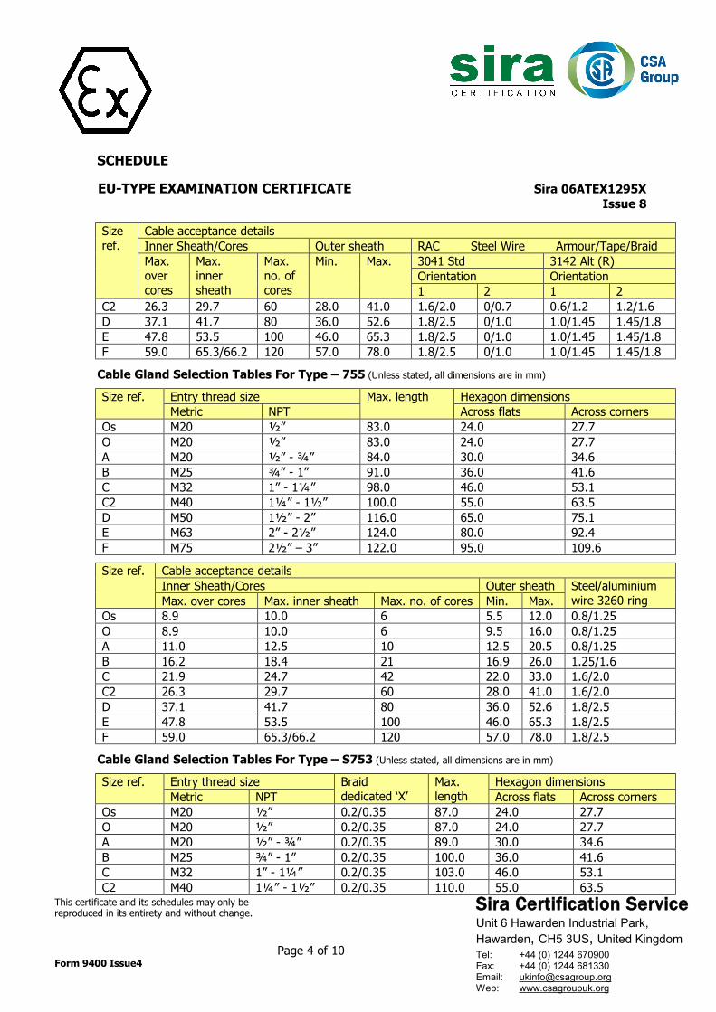
Cable Gland Selection Tables For Type – 753 (Unless stated, all dimensions are in mm)
Size ref. Entry thread size Braid dedicated ‘X’ Max. length
Hexagon dimensions Metric NPT Across flats Across corners
Os M20 ½” 0.2/0.35 87.0 24.0 27.7 O M20 ½” 0.2/0.35 87.0 24.0 27.7 A M20 ½” - ¾” 0.2/0.35 89.0 30.0 34.6 B M25 ¾” – 1” 0.2/0.35 100.0 36.0 41.6 C M32 1” – 1¼” 0.2/0.35 103.0 46.0 53.1 C2 M40 1¼” – 1½” 0.2/0.35 110.0 55.0 63.5 D M50 1½” – 2” 0.2/0.35 133.0 65.0 75.1 E M63 2” – 2½” 0.2/0.35 133.0 80.0 92.4 F M75 2½” – 3” 0.2/0.35 140.0 95.0 109.6
Size ref.
Cable acceptance details Inner Sheath/Cores Outer sheath RAC Steel Wire Armour/Tape/Braid Max. over cores
Max. inner sheath
Max. no. of cores
Min. Max. 3041 Std 3142 Alt (R) Orientation Orientation 1 2 1 2
Os 8.9 10.0 6 5.5 12.0 0.8/1.25 0/0.8 - - O 8.9 10.0 6 9.5 16.0 0.8/1.25 0/0.8 - - A 11.0 12.5 10 12.5 20.5 0.8/1.25 0/0.8 - - B 16.2 18.4 21 16.9 26.0 1.25/1.6 0/0.7 0.5/0.9 0.9/1.25 C 21.9 24.7 42 22.0 33.0 1.6/2.0 0/0.7 0.6/1.2 1.2/1.6
Sira Certification Service Unit 6 Hawarden Industrial Park, Hawarden, CH5 3US, United Kingdom
Tel: +44 (0) 1244 670900 Fax: +44 (0) 1244 681330 Email: [email protected] Web: www.csagroupuk.org
SCHEDULE EU-TYPE EXAMINATION CERTIFICATE Sira 06ATEX1295X Issue 8
This certificate and its schedules may only be reproduced in its entirety and without change. Page 4 of 10 Form 9400 Issue4
Size ref.
Cable acceptance details Inner Sheath/Cores Outer sheath RAC Steel Wire Armour/Tape/Braid Max. over cores
Max. inner sheath
Max. no. of cores
Min. Max. 3041 Std 3142 Alt (R) Orientation Orientation 1 2 1 2
C2 26.3 29.7 60 28.0 41.0 1.6/2.0 0/0.7 0.6/1.2 1.2/1.6 D 37.1 41.7 80 36.0 52.6 1.8/2.5 0/1.0 1.0/1.45 1.45/1.8 E 47.8 53.5 100 46.0 65.3 1.8/2.5 0/1.0 1.0/1.45 1.45/1.8 F 59.0 65.3/66.2 120 57.0 78.0 1.8/2.5 0/1.0 1.0/1.45 1.45/1.8
Cable Gland Selection Tables For Type – 755 (Unless stated, all dimensions are in mm)
Size ref. Entry thread size Max. length Hexagon dimensions
Metric NPT Across flats Across corners Os M20 ½” 83.0 24.0 27.7 O M20 ½” 83.0 24.0 27.7 A M20 ½” - ¾” 84.0 30.0 34.6 B M25 ¾” - 1” 91.0 36.0 41.6 C M32 1” - 1¼” 98.0 46.0 53.1 C2 M40 1¼” - 1½” 100.0 55.0 63.5 D M50 1½” - 2” 116.0 65.0 75.1 E M63 2” - 2½” 124.0 80.0 92.4 F M75 2½” – 3” 122.0 95.0 109.6
Size ref. Cable acceptance details
Inner Sheath/Cores Outer sheath Steel/aluminium wire 3260 ring Max. over cores Max. inner sheath Max. no. of cores Min. Max.
Os 8.9 10.0 6 5.5 12.0 0.8/1.25 O 8.9 10.0 6 9.5 16.0 0.8/1.25 A 11.0 12.5 10 12.5 20.5 0.8/1.25 B 16.2 18.4 21 16.9 26.0 1.25/1.6 C 21.9 24.7 42 22.0 33.0 1.6/2.0 C2 26.3 29.7 60 28.0 41.0 1.6/2.0 D 37.1 41.7 80 36.0 52.6 1.8/2.5 E 47.8 53.5 100 46.0 65.3 1.8/2.5 F 59.0 65.3/66.2 120 57.0 78.0 1.8/2.5
Cable Gland Selection Tables For Type – S753 (Unless stated, all dimensions are in mm)
Size ref. Entry thread size Braid
dedicated ‘X’ Max. length
Hexagon dimensions Metric NPT Across flats Across corners
Os M20 ½” 0.2/0.35 87.0 24.0 27.7 O M20 ½” 0.2/0.35 87.0 24.0 27.7 A M20 ½” - ¾” 0.2/0.35 89.0 30.0 34.6 B M25 ¾” - 1” 0.2/0.35 100.0 36.0 41.6 C M32 1” - 1¼” 0.2/0.35 103.0 46.0 53.1 C2 M40 1¼” - 1½” 0.2/0.35 110.0 55.0 63.5
Sira Certification Service Unit 6 Hawarden Industrial Park, Hawarden, CH5 3US, United Kingdom
Tel: +44 (0) 1244 670900 Fax: +44 (0) 1244 681330 Email: [email protected] Web: www.csagroupuk.org
SCHEDULE EU-TYPE EXAMINATION CERTIFICATE Sira 06ATEX1295X Issue 8
This certificate and its schedules may only be reproduced in its entirety and without change. Page 5 of 10 Form 9400 Issue4
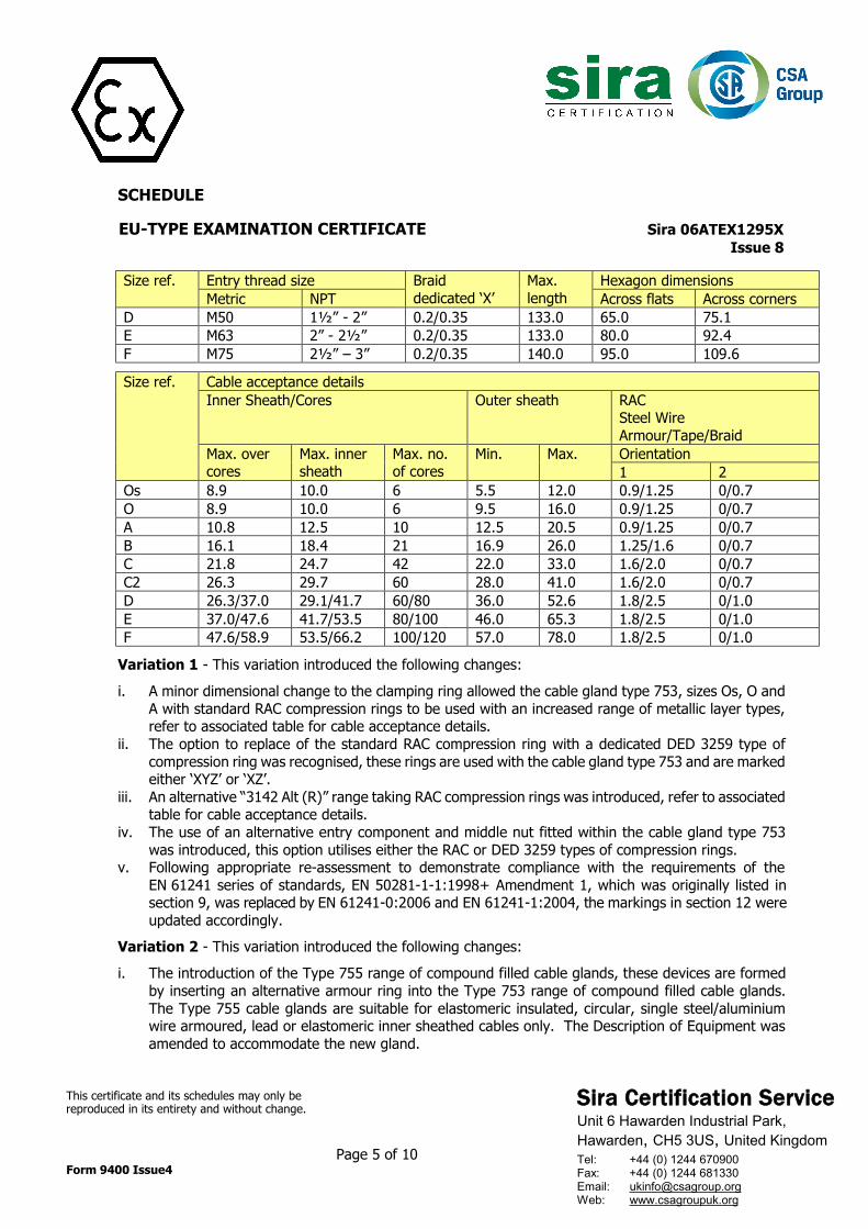
Size ref. Entry thread size Braid dedicated ‘X’
Max. length
Hexagon dimensions Metric NPT Across flats Across corners
D M50 1½” - 2” 0.2/0.35 133.0 65.0 75.1 E M63 2” - 2½” 0.2/0.35 133.0 80.0 92.4 F M75 2½” – 3” 0.2/0.35 140.0 95.0 109.6
Size ref. Cable acceptance details
Inner Sheath/Cores Outer sheath RAC Steel Wire Armour/Tape/Braid
Max. over cores
Max. inner sheath
Max. no. of cores
Min. Max. Orientation 1 2
Os 8.9 10.0 6 5.5 12.0 0.9/1.25 0/0.7 O 8.9 10.0 6 9.5 16.0 0.9/1.25 0/0.7 A 10.8 12.5 10 12.5 20.5 0.9/1.25 0/0.7 B 16.1 18.4 21 16.9 26.0 1.25/1.6 0/0.7 C 21.8 24.7 42 22.0 33.0 1.6/2.0 0/0.7 C2 26.3 29.7 60 28.0 41.0 1.6/2.0 0/0.7 D 26.3/37.0 29.1/41.7 60/80 36.0 52.6 1.8/2.5 0/1.0 E 37.0/47.6 41.7/53.5 80/100 46.0 65.3 1.8/2.5 0/1.0 F 47.6/58.9 53.5/66.2 100/120 57.0 78.0 1.8/2.5 0/1.0
Variation 1 - This variation introduced the following changes:
i. A minor dimensional change to the clamping ring allowed the cable gland type 753, sizes Os, O and
A with standard RAC compression rings to be used with an increased range of metallic layer types, refer to associated table for cable acceptance details.
ii. The option to replace of the standard RAC compression ring with a dedicated DED 3259 type of compression ring was recognised, these rings are used with the cable gland type 753 and are marked either ‘XYZ’ or ‘XZ’.
iii. An alternative “3142 Alt (R)” range taking RAC compression rings was introduced, refer to associated table for cable acceptance details.
iv. The use of an alternative entry component and middle nut fitted within the cable gland type 753 was introduced, this option utilises either the RAC or DED 3259 types of compression rings.
v. Following appropriate re-assessment to demonstrate compliance with the requirements of the EN 61241 series of standards, EN 50281-1-1:1998+ Amendment 1, which was originally listed in section 9, was replaced by EN 61241-0:2006 and EN 61241-1:2004, the markings in section 12 were updated accordingly.
Variation 2 - This variation introduced the following changes:
i. The introduction of the Type 755 range of compound filled cable glands, these devices are formed
by inserting an alternative armour ring into the Type 753 range of compound filled cable glands. The Type 755 cable glands are suitable for elastomeric insulated, circular, single steel/aluminium wire armoured, lead or elastomeric inner sheathed cables only. The Description of Equipment was amended to accommodate the new gland.
Sira Certification Service Unit 6 Hawarden Industrial Park, Hawarden, CH5 3US, United Kingdom
Tel: +44 (0) 1244 670900 Fax: +44 (0) 1244 681330 Email: [email protected] Web: www.csagroupuk.org
SCHEDULE EU-TYPE EXAMINATION CERTIFICATE Sira 06ATEX1295X Issue 8
This certificate and its schedules may only be reproduced in its entirety and without change. Page 6 of 10 Form 9400 Issue4
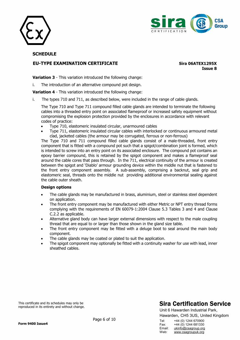
Variation 3 - This variation introduced the following change:
i. The introduction of an alternative compound pot design.
Variation 4 - This variation introduced the following change:
i. The types 710 and 711, as described below, were included in the range of cable glands.
The Type 710 and Type 711 compound filled cable glands are intended to terminate the following cables into a threaded entry point on associated flameproof or increased safety equipment without compromising the explosion protection provided by the enclosures in accordance with relevant codes of practice: • Type 710, elastomeric insulated circular, unarmoured cables • Type 711, elastomeric insulated circular cables with interlocked or continuous armoured metal
clad, jacketed cables (the armour may be corrugated, ferrous or non-ferrous) The Type 710 and 711 compound filled cable glands consist of a male-threaded, front entry component that is fitted with a compound pot such that a spigot/combination joint is formed, which is intended to screw into an entry point on its associated enclosure. The compound pot contains an epoxy barrier compound, this is retained by the spigot component and makes a flameproof seal around the cable cores that pass through. In the 711, electrical continuity of the armour is created between the spigot and ‘Diablo’ armour grounding device within the middle nut that is fastened to the front entry component assembly. A sub-assembly, comprising a backnut, seal grip and elastomeric seal, threads onto the middle nut providing additional environmental sealing against the cable outer sheath.
Design options
• The cable glands may be manufactured in brass, aluminium, steel or stainless steel dependent
on application. • The front entry component may be manufactured with either Metric or NPT entry thread forms
complying with the requirements of EN 60079-1:2004 Clause 5.3 Tables 3 and 4 and Clause C.2.2 as applicable.
• Alternative gland body can have larger external dimensions with respect to the male coupling thread that are equal to or larger than those shown in the gland size table.
• The front entry component may be fitted with a deluge boot to seal around the main body component.
• The cable glands may be coated or plated to suit the application. • The spigot component may optionally be fitted with a continuity washer for use with lead, inner
sheathed cables.
Sira Certification Service Unit 6 Hawarden Industrial Park, Hawarden, CH5 3US, United Kingdom
Tel: +44 (0) 1244 670900 Fax: +44 (0) 1244 681330 Email: [email protected] Web: www.csagroupuk.org
SCHEDULE EU-TYPE EXAMINATION CERTIFICATE Sira 06ATEX1295X Issue 8
This certificate and its schedules may only be reproduced in its entirety and without change. Page 7 of 10 Form 9400 Issue4
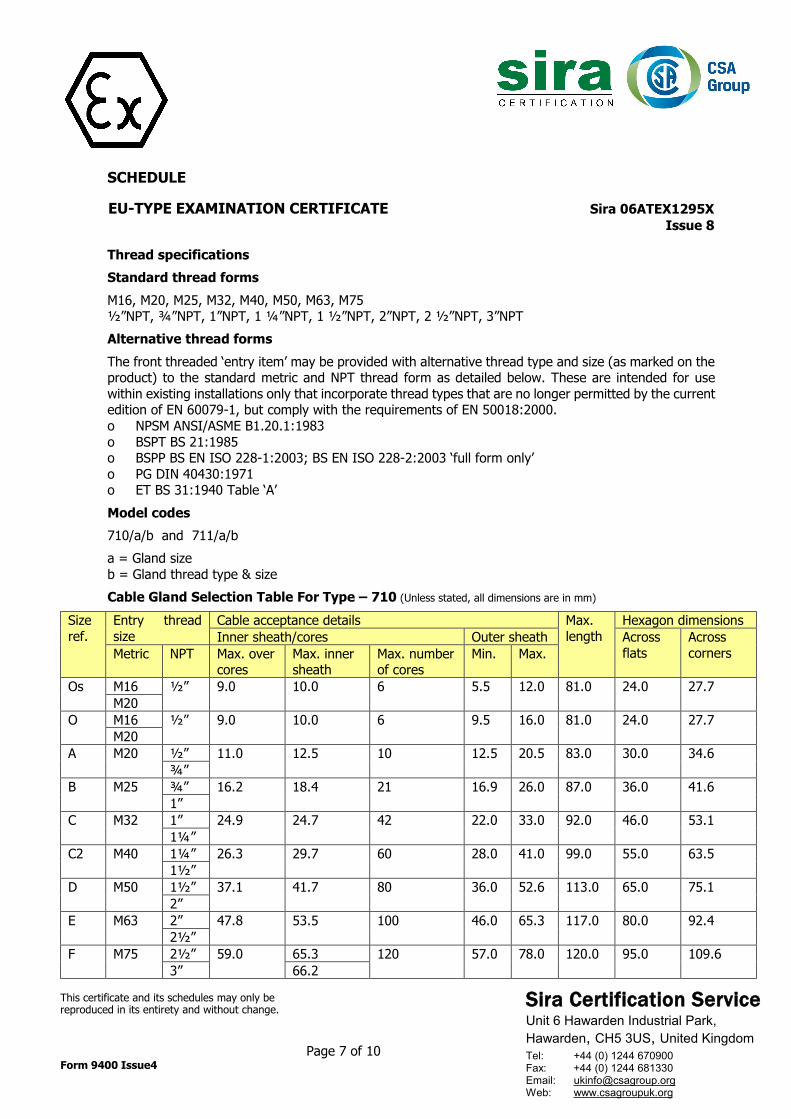
Thread specifications Standard thread forms M16, M20, M25, M32, M40, M50, M63, M75 ½”NPT, ¾”NPT, 1”NPT, 1 ¼”NPT, 1 ½”NPT, 2”NPT, 2 ½”NPT, 3”NPT Alternative thread forms The front threaded ‘entry item’ may be provided with alternative thread type and size (as marked on the product) to the standard metric and NPT thread form as detailed below. These are intended for use within existing installations only that incorporate thread types that are no longer permitted by the current edition of EN 60079-1, but comply with the requirements of EN 50018:2000. o NPSM ANSI/ASME B1.20.1:1983 o BSPT BS 21:1985 o BSPP BS EN ISO 228-1:2003; BS EN ISO 228-2:2003 ‘full form only’ o PG DIN 40430:1971 o ET BS 31:1940 Table ‘A’ Model codes 710/a/b and 711/a/b a = Gland size b = Gland thread type & size Cable Gland Selection Table For Type – 710 (Unless stated, all dimensions are in mm)
Size ref.
Entry thread size
Cable acceptance details Max. length
Hexagon dimensions Inner sheath/cores Outer sheath Across
flats Across corners Metric NPT Max. over
cores Max. inner sheath
Max. number of cores
Min. Max.
Os M16 ½” 9.0 10.0 6 5.5 12.0 81.0 24.0 27.7 M20
O M16 ½” 9.0 10.0 6 9.5 16.0 81.0 24.0 27.7 M20
A M20 ½” 11.0 12.5 10 12.5 20.5 83.0 30.0 34.6 ¾”
B M25 ¾” 16.2 18.4 21 16.9 26.0 87.0 36.0 41.6 1”
C M32 1” 24.9 24.7 42 22.0 33.0 92.0 46.0 53.1 1¼”
C2 M40 1¼” 26.3 29.7 60 28.0 41.0 99.0 55.0 63.5 1½”
D M50 1½” 37.1 41.7 80 36.0 52.6 113.0 65.0 75.1 2”
E M63 2” 47.8 53.5 100 46.0 65.3 117.0 80.0 92.4 2½”
F M75 2½” 59.0 65.3 120 57.0 78.0 120.0 95.0 109.6 3” 66.2
Sira Certification Service Unit 6 Hawarden Industrial Park, Hawarden, CH5 3US, United Kingdom
Tel: +44 (0) 1244 670900 Fax: +44 (0) 1244 681330 Email: [email protected] Web: www.csagroupuk.org
SCHEDULE EU-TYPE EXAMINATION CERTIFICATE Sira 06ATEX1295X Issue 8
This certificate and its schedules may only be reproduced in its entirety and without change. Page 8 of 10 Form 9400 Issue4
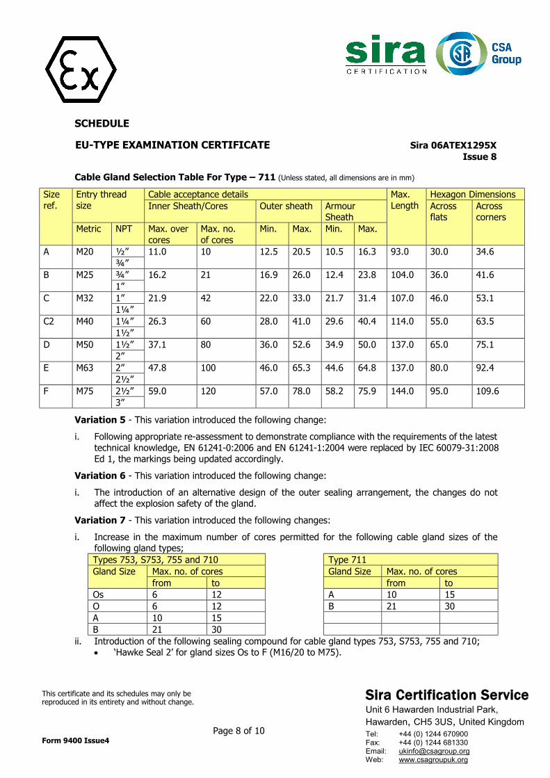
Cable Gland Selection Table For Type – 711 (Unless stated, all dimensions are in mm) Size ref.
Entry thread size
Cable acceptance details Max. Length
Hexagon Dimensions Inner Sheath/Cores Outer sheath Armour
Sheath Across flats
Across corners
Metric NPT Max. over cores
Max. no. of cores
Min. Max. Min. Max.
A M20 ½” 11.0 10 12.5 20.5 10.5 16.3 93.0 30.0 34.6 ¾”
B M25 ¾” 16.2 21 16.9 26.0 12.4 23.8 104.0 36.0 41.6 1”
C M32 1” 21.9 42 22.0 33.0 21.7 31.4 107.0 46.0 53.1 1¼”
C2 M40 1¼” 26.3 60 28.0 41.0 29.6 40.4 114.0 55.0 63.5 1½”
D M50 1½” 37.1 80 36.0 52.6 34.9 50.0 137.0 65.0 75.1 2”
E M63 2” 47.8 100 46.0 65.3 44.6 64.8 137.0 80.0 92.4 2½”
F M75 2½” 59.0 120 57.0 78.0 58.2 75.9 144.0 95.0 109.6 3”
Variation 5 - This variation introduced the following change:
i. Following appropriate re-assessment to demonstrate compliance with the requirements of the latest
technical knowledge, EN 61241-0:2006 and EN 61241-1:2004 were replaced by IEC 60079-31:2008 Ed 1, the markings being updated accordingly.
Variation 6 - This variation introduced the following change:
i. The introduction of an alternative design of the outer sealing arrangement, the changes do not
affect the explosion safety of the gland.
Variation 7 - This variation introduced the following changes:
i. Increase in the maximum number of cores permitted for the following cable gland sizes of the following gland types; Types 753, S753, 755 and 710 Type 711 Gland Size Max. no. of cores Gland Size Max. no. of cores
from to from to Os 6 12 A 10 15 O 6 12 B 21 30 A 10 15 B 21 30
ii. Introduction of the following sealing compound for cable gland types 753, S753, 755 and 710; • ‘Hawke Seal 2’ for gland sizes Os to F (M16/20 to M75).
Sira Certification Service Unit 6 Hawarden Industrial Park, Hawarden, CH5 3US, United Kingdom
Tel: +44 (0) 1244 670900 Fax: +44 (0) 1244 681330 Email: [email protected] Web: www.csagroupuk.org
SCHEDULE EU-TYPE EXAMINATION CERTIFICATE Sira 06ATEX1295X Issue 8
This certificate and its schedules may only be reproduced in its entirety and without change. Page 9 of 10 Form 9400 Issue4
iii. Removal of the following Special Condition For Safe Use: • The cable glands shall only be used where the temperature, at the point of entry, is within the
range -60°C to +80°C or -50°C to +60°C (as marked on the product). iv. Inclusion of alternate grades of brass and stainless steel for the materials of manufacture. v. The recognition of minor drawing modifications; these amendments are administrative or involve
changes to components and design that do not affect the aspects of the product that are relevant to explosion safety, and comprise of those detailed below: • Changing of compound material reference designations. • Addition of non-relevant thread size details. • Redraw to separate details onto more than one drawing sheet. • Dimensional corrections.
vi. Following appropriate assessment to demonstrate compliance with the latest technical knowledge, EN 60079-0:2009, EN 60079-1:2007 and IEC 60079-31:2008 Ed 1, were replaced by EN 60079-0:2012, EN 60079-1:2014 and EN 60079-31:2014, the product markings being amended as applicable to recognise the new standards.
Variation 8 - This variation introduced the following change:
i. Issue 7 of this certificate allowed the maximum number of cores to be increased; this has now been
formally recognised on the drawings that are associated with this change. ii. It was recognised that the flameproof joints are not intended to be repaired; consequently, the
associated Specific Condition of Use was amended. iii. Following appropriate assessment to demonstrate compliance with the latest technical knowledge,
EN 60079-0:2012 and EN 60079-7:2007 were replaced by EN 60079-0:2012/A11:2013 and EN 60079-7:2015, the markings were amended to recognise the new standards.
iv. The certificate schedule was appropriately amended to add the specification of the alternative types of thread forms that are available.
14 DESCRIPTIVE DOCUMENTS 14.1 Drawings
Refer to Certificate Annexe. 14.2 Associated Sira Reports and Certificate History
Issue Date Report no. Comment 0 26 October 2006 R51L15678A The release of the prime certificate. 1 19 November 2007 R51L17327B This Issue covers the following changes:
• All previously issued certification was rationalised into a single certificate, Issue 1, Issue 0 referenced above is only intended to reflect the history of the previous certification and has not been issued as a document in this format.
• The introduction of Variation 1. 2 28 October 2008 R51L19087A The introduction of Variation 2. 3 28 May 2009 R51L20192A The introduction of Variation 3. 4 9 September 2009 R51L20767A The introduction of Variation 4. 5 26 April 2010 R20859A/00 The introduction of Variation 5.
Sira Certification Service Unit 6 Hawarden Industrial Park, Hawarden, CH5 3US, United Kingdom
Tel: +44 (0) 1244 670900 Fax: +44 (0) 1244 681330 Email: [email protected] Web: www.csagroupuk.org
SCHEDULE EU-TYPE EXAMINATION CERTIFICATE Sira 06ATEX1295X Issue 8
This certificate and its schedules may only be reproduced in its entirety and without change. Page 10 of 10 Form 9400 Issue4
Issue Date Report no. Comment 6 31 August 2010 R23138A/00 The introduction of Variation 6. 7 30 March 2016 R70026937A The introduction of Variation 7. 8 21 November 2017 R70108149A This Issue covers the following changes:
• EC Type-Examination Certificate in accordance with 94/9/EC updated to EU Type-Examination Certificate in accordance with Directive 2014/34/EU. (In accordance with Article 41 of Directive 2014/34/EU, EC Type-Examination Certificates referring to 94/9/EC that were in existence prior to the date of application of 2014/34/EU (20 April 2016) may be referenced as if they were issued in accordance with Directive 2014/34/EU. Variations to such EC Type-Examination Certificates may continue to bear the original certificate number issued prior to 20 April 2016.)
• The introduction of Variation 8. 15 SPECIFIC CONDITIONS OF USE (denoted by X after the certificate number) 15.1 The entry component threads will be suitably sealed using a method that is applicable to the associated
equipment to which the gland will be attached, this will be in accordance with the relevant, installation code of practice and will ensure that any ingress protection sealing requirements are maintained.
15.2 The flameproof joints shall not be repaired. 16 ESSENTIAL HEALTH AND SAFETY REQUIREMENTS OF ANNEX II (EHSRs) The relevant EHSRs that are not addressed by the standards listed in this certificate have been identified
and individually assessed in the reports listed in Section 14.2. 17 CONDITIONS OF MANUFACTURE 17.1 The use of this certificate is subject to the Regulations Applicable to Holders of Sira Certificates. 17.2 Holders of EU-Type Examination Certificates are required to comply with the conformity to type
requirements defined in Article 13 of Directive 2014/34/EU.
Sira Certification Service Unit 6 Hawarden Industrial Park, Hawarden, CH5 3US, United Kingdom
Tel: +44 (0) 1244 670900 Fax: +44 (0) 1244 681330 Email: [email protected] Web: www.csagroupuk.org
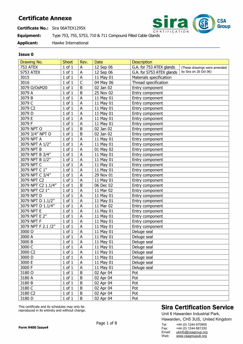
Certificate Annexe Certificate No.: Sira 06ATEX1295X Equipment: Type 753, 755, S753, 710 & 711 Compound Filled Cable Glands Applicant: Hawke International
This certificate and its schedules may only be reproduced in its entirety and without change. Page 1 of 8 Form 9400 Issue4
Issue 0 Drawing No. Sheet Rev. Date Description 753 ATEX 1 of 1 A 12 Sep 06 G.A. for 753 ATEX glands (These drawings were amended
by Sira on 26 Oct 06) S753 ATEX 1 of 1 A 12 Sep 06 G.A. for S753 ATEX glands 3015 1 of 1 A 11 May 01 Materials specification 3016 1 of 1 C 04 May 06 Thread specification 3079 O/OsM20 1 of 1 B 02 Jan 02 Entry component 3079 A 1 of 1 B 25 Nov 02 Entry component 3079 B 1 of 1 A 11 May 01 Entry component 3079 C 1 of 1 A 11 May 01 Entry component 3079 C2 1 of 1 A 11 May 01 Entry component 3079 D 1 of 1 A 11 May 01 Entry component 3079 E 1 of 1 A 11 May 01 Entry component 3079 F 1 of 1 A 11 May 01 Entry component 3079 NPT O 1 of 1 B 02 Jan 02 Entry component 3079 3/4” NPT O 1 of 1 B 02 Jan 02 Entry component 3079 NPT A 1 of 1 A 11 May 01 Entry component 3079 NPT A 1/2” 1 of 1 A 11 May 01 Entry component 3079 NPT B 1 of 1 A 01 May 02 Entry component 3079 NPT B 3/4” 1 of 1 A 11 May 01 Entry component 3079 NPT B 1/2” 1 of 1 A 11 May 01 Entry component 3079 NPT C 1 of 1 A 11 May 01 Entry component 3079 NPT C 1” 1 of 1 A 11 May 01 Entry component 3079 NPT C 3/4” 1 of 1 A 29 Nov 01 Entry component 3079 NPT C2 1 of 1 A 11 May 01 Entry component 3079 NPT C2 1.1/4” 1 of 1 B 06 Dec 02 Entry component 3079 NPT C2 1” 1 of 1 A 11 Mar 02 Entry component 3079 NPT D 1 of 1 A 11 May 01 Entry component 3079 NPT D 1.1/2” 1 of 1 A 11 May 01 Entry component 3079 NPT D 1.1/4” 1 of 1 A 11 Mar 02 Entry component 3079 NPT E 1 of 1 A 11 May 01 Entry component 3079 NPT E 2” 1 of 1 A 11 May 01 Entry component 3079 NPT F 1 of 1 A 11 May 01 Entry component 3079 NPT F 2.1 /2” 1 of 1 A 11 May 01 Entry component 3000 O 1 of 1 A 11 May 01 Deluge seal 3000 A 1 of 1 A 11 May 01 Deluge seal 3000 B 1 of 1 A 11 May 01 Deluge seal 3000 C 1 of 1 A 11 May 01 Deluge seal 3000 C2 1 of 1 A 11 May 01 Deluge seal 3000 D 1 of 1 A 11 May 01 Deluge seal 3000 E 1 of 1 A 11 May 01 Deluge seal 3000 F 1 of 1 A 11 May 01 Deluge seal 3180 O 1 of 1 B 02 Apr 04 Pot 3180 A 1 of 1 B 02 Apr 04 Pot 3180 B 1 of 1 B 02 Apr 04 Pot 3180 C 1 of 1 B 02 Apr 04 Pot 3180 C2 1 of 1 B 02 Apr 04 Pot 3180 D 1 of 1 B 02 Apr 04 Pot
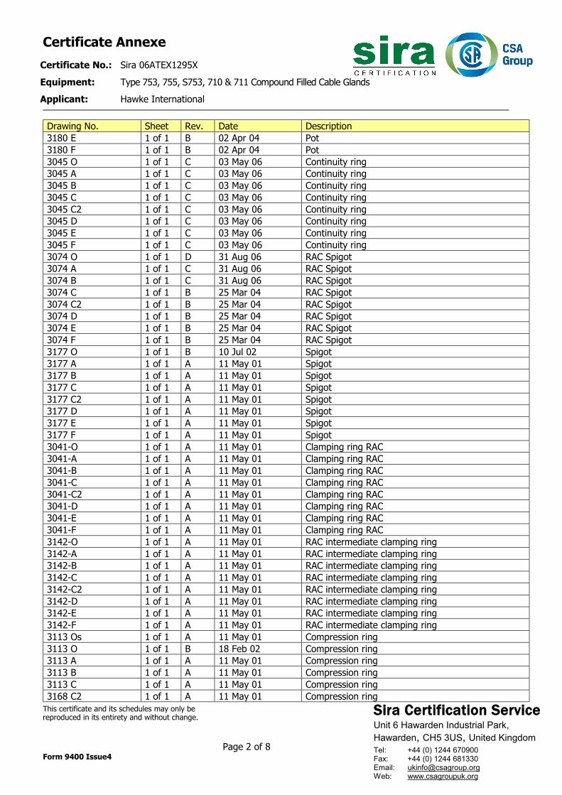
Sira Certification Service Unit 6 Hawarden Industrial Park, Hawarden, CH5 3US, United Kingdom
Tel: +44 (0) 1244 670900 Fax: +44 (0) 1244 681330 Email: [email protected] Web: www.csagroupuk.org
Certificate Annexe Certificate No.: Sira 06ATEX1295X Equipment: Type 753, 755, S753, 710 & 711 Compound Filled Cable Glands Applicant: Hawke International
This certificate and its schedules may only be reproduced in its entirety and without change. Page 2 of 8 Form 9400 Issue4
Drawing No. Sheet Rev. Date Description 3180 E 1 of 1 B 02 Apr 04 Pot 3180 F 1 of 1 B 02 Apr 04 Pot 3045 O 1 of 1 C 03 May 06 Continuity ring 3045 A 1 of 1 C 03 May 06 Continuity ring 3045 B 1 of 1 C 03 May 06 Continuity ring 3045 C 1 of 1 C 03 May 06 Continuity ring 3045 C2 1 of 1 C 03 May 06 Continuity ring 3045 D 1 of 1 C 03 May 06 Continuity ring 3045 E 1 of 1 C 03 May 06 Continuity ring 3045 F 1 of 1 C 03 May 06 Continuity ring 3074 O 1 of 1 D 31 Aug 06 RAC Spigot 3074 A 1 of 1 C 31 Aug 06 RAC Spigot 3074 B 1 of 1 C 31 Aug 06 RAC Spigot 3074 C 1 of 1 B 25 Mar 04 RAC Spigot 3074 C2 1 of 1 B 25 Mar 04 RAC Spigot 3074 D 1 of 1 B 25 Mar 04 RAC Spigot 3074 E 1 of 1 B 25 Mar 04 RAC Spigot 3074 F 1 of 1 B 25 Mar 04 RAC Spigot 3177 O 1 of 1 B 10 Jul 02 Spigot 3177 A 1 of 1 A 11 May 01 Spigot 3177 B 1 of 1 A 11 May 01 Spigot 3177 C 1 of 1 A 11 May 01 Spigot 3177 C2 1 of 1 A 11 May 01 Spigot 3177 D 1 of 1 A 11 May 01 Spigot 3177 E 1 of 1 A 11 May 01 Spigot 3177 F 1 of 1 A 11 May 01 Spigot 3041-O 1 of 1 A 11 May 01 Clamping ring RAC 3041-A 1 of 1 A 11 May 01 Clamping ring RAC 3041-B 1 of 1 A 11 May 01 Clamping ring RAC 3041-C 1 of 1 A 11 May 01 Clamping ring RAC 3041-C2 1 of 1 A 11 May 01 Clamping ring RAC 3041-D 1 of 1 A 11 May 01 Clamping ring RAC 3041-E 1 of 1 A 11 May 01 Clamping ring RAC 3041-F 1 of 1 A 11 May 01 Clamping ring RAC 3142-O 1 of 1 A 11 May 01 RAC intermediate clamping ring 3142-A 1 of 1 A 11 May 01 RAC intermediate clamping ring 3142-B 1 of 1 A 11 May 01 RAC intermediate clamping ring 3142-C 1 of 1 A 11 May 01 RAC intermediate clamping ring 3142-C2 1 of 1 A 11 May 01 RAC intermediate clamping ring 3142-D 1 of 1 A 11 May 01 RAC intermediate clamping ring 3142-E 1 of 1 A 11 May 01 RAC intermediate clamping ring 3142-F 1 of 1 A 11 May 01 RAC intermediate clamping ring 3113 Os 1 of 1 A 11 May 01 Compression ring 3113 O 1 of 1 B 18 Feb 02 Compression ring 3113 A 1 of 1 A 11 May 01 Compression ring 3113 B 1 of 1 A 11 May 01 Compression ring 3113 C 1 of 1 A 11 May 01 Compression ring 3168 C2 1 of 1 A 11 May 01 Compression ring
Sira Certification Service Unit 6 Hawarden Industrial Park, Hawarden, CH5 3US, United Kingdom
Tel: +44 (0) 1244 670900 Fax: +44 (0) 1244 681330 Email: [email protected] Web: www.csagroupuk.org
Certificate Annexe Certificate No.: Sira 06ATEX1295X Equipment: Type 753, 755, S753, 710 & 711 Compound Filled Cable Glands Applicant: Hawke International
This certificate and its schedules may only be reproduced in its entirety and without change. Page 3 of 8 Form 9400 Issue4
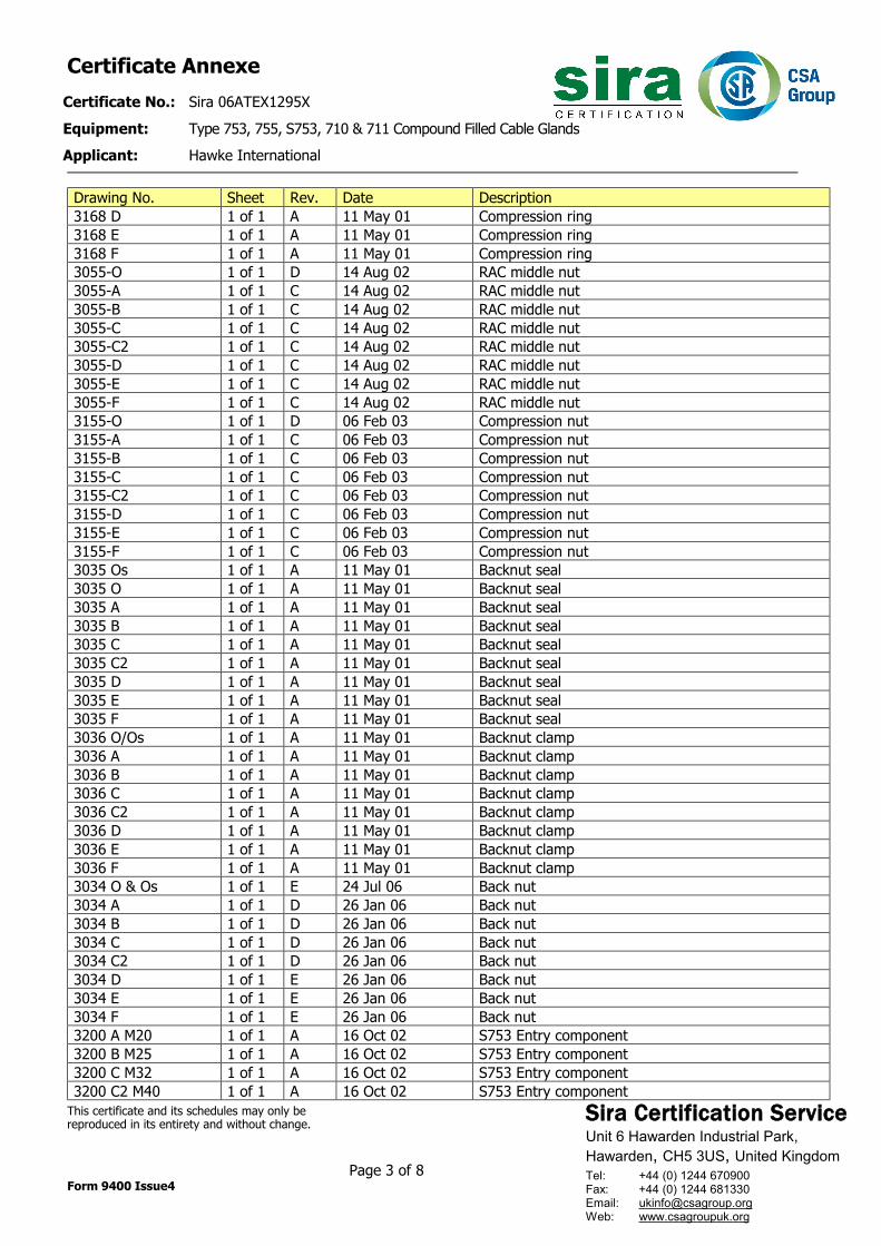
Drawing No. Sheet Rev. Date Description 3168 D 1 of 1 A 11 May 01 Compression ring 3168 E 1 of 1 A 11 May 01 Compression ring 3168 F 1 of 1 A 11 May 01 Compression ring 3055-O 1 of 1 D 14 Aug 02 RAC middle nut 3055-A 1 of 1 C 14 Aug 02 RAC middle nut 3055-B 1 of 1 C 14 Aug 02 RAC middle nut 3055-C 1 of 1 C 14 Aug 02 RAC middle nut 3055-C2 1 of 1 C 14 Aug 02 RAC middle nut 3055-D 1 of 1 C 14 Aug 02 RAC middle nut 3055-E 1 of 1 C 14 Aug 02 RAC middle nut 3055-F 1 of 1 C 14 Aug 02 RAC middle nut 3155-O 1 of 1 D 06 Feb 03 Compression nut 3155-A 1 of 1 C 06 Feb 03 Compression nut 3155-B 1 of 1 C 06 Feb 03 Compression nut 3155-C 1 of 1 C 06 Feb 03 Compression nut 3155-C2 1 of 1 C 06 Feb 03 Compression nut 3155-D 1 of 1 C 06 Feb 03 Compression nut 3155-E 1 of 1 C 06 Feb 03 Compression nut 3155-F 1 of 1 C 06 Feb 03 Compression nut 3035 Os 1 of 1 A 11 May 01 Backnut seal 3035 O 1 of 1 A 11 May 01 Backnut seal 3035 A 1 of 1 A 11 May 01 Backnut seal 3035 B 1 of 1 A 11 May 01 Backnut seal 3035 C 1 of 1 A 11 May 01 Backnut seal 3035 C2 1 of 1 A 11 May 01 Backnut seal 3035 D 1 of 1 A 11 May 01 Backnut seal 3035 E 1 of 1 A 11 May 01 Backnut seal 3035 F 1 of 1 A 11 May 01 Backnut seal 3036 O/Os 1 of 1 A 11 May 01 Backnut clamp 3036 A 1 of 1 A 11 May 01 Backnut clamp 3036 B 1 of 1 A 11 May 01 Backnut clamp 3036 C 1 of 1 A 11 May 01 Backnut clamp 3036 C2 1 of 1 A 11 May 01 Backnut clamp 3036 D 1 of 1 A 11 May 01 Backnut clamp 3036 E 1 of 1 A 11 May 01 Backnut clamp 3036 F 1 of 1 A 11 May 01 Backnut clamp 3034 O & Os 1 of 1 E 24 Jul 06 Back nut 3034 A 1 of 1 D 26 Jan 06 Back nut 3034 B 1 of 1 D 26 Jan 06 Back nut 3034 C 1 of 1 D 26 Jan 06 Back nut 3034 C2 1 of 1 D 26 Jan 06 Back nut 3034 D 1 of 1 E 26 Jan 06 Back nut 3034 E 1 of 1 E 26 Jan 06 Back nut 3034 F 1 of 1 E 26 Jan 06 Back nut 3200 A M20 1 of 1 A 16 Oct 02 S753 Entry component 3200 B M25 1 of 1 A 16 Oct 02 S753 Entry component 3200 C M32 1 of 1 A 16 Oct 02 S753 Entry component 3200 C2 M40 1 of 1 A 16 Oct 02 S753 Entry component
Sira Certification Service Unit 6 Hawarden Industrial Park, Hawarden, CH5 3US, United Kingdom
Tel: +44 (0) 1244 670900 Fax: +44 (0) 1244 681330 Email: [email protected] Web: www.csagroupuk.org
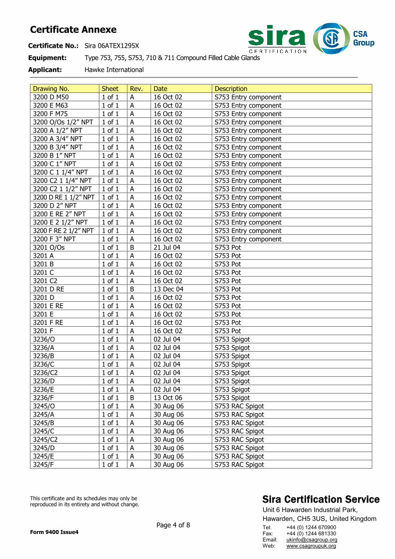
Certificate Annexe Certificate No.: Sira 06ATEX1295X Equipment: Type 753, 755, S753, 710 & 711 Compound Filled Cable Glands Applicant: Hawke International
This certificate and its schedules may only be reproduced in its entirety and without change. Page 4 of 8 Form 9400 Issue4
Drawing No. Sheet Rev. Date Description 3200 D M50 1 of 1 A 16 Oct 02 S753 Entry component 3200 E M63 1 of 1 A 16 Oct 02 S753 Entry component 3200 F M75 1 of 1 A 16 Oct 02 S753 Entry component 3200 O/Os 1/2” NPT 1 of 1 A 16 Oct 02 S753 Entry component 3200 A 1/2” NPT 1 of 1 A 16 Oct 02 S753 Entry component 3200 A 3/4” NPT 1 of 1 A 16 Oct 02 S753 Entry component 3200 B 3/4” NPT 1 of 1 A 16 Oct 02 S753 Entry component 3200 B 1” NPT 1 of 1 A 16 Oct 02 S753 Entry component 3200 C 1” NPT 1 of 1 A 16 Oct 02 S753 Entry component 3200 C 1 1/4” NPT 1 of 1 A 16 Oct 02 S753 Entry component 3200 C2 1 1/4” NPT 1 of 1 A 16 Oct 02 S753 Entry component 3200 C2 1 1/2” NPT 1 of 1 A 16 Oct 02 S753 Entry component 3200 D RE 1 1/2” NPT 1 of 1 A 16 Oct 02 S753 Entry component 3200 D 2” NPT 1 of 1 A 16 Oct 02 S753 Entry component 3200 E RE 2” NPT 1 of 1 A 16 Oct 02 S753 Entry component 3200 E 2 1/2” NPT 1 of 1 A 16 Oct 02 S753 Entry component 3200 F RE 2 1/2” NPT 1 of 1 A 16 Oct 02 S753 Entry component 3200 F 3” NPT 1 of 1 A 16 Oct 02 S753 Entry component 3201 O/Os 1 of 1 B 21 Jul 04 S753 Pot 3201 A 1 of 1 A 16 Oct 02 S753 Pot 3201 B 1 of 1 A 16 Oct 02 S753 Pot 3201 C 1 of 1 A 16 Oct 02 S753 Pot 3201 C2 1 of 1 A 16 Oct 02 S753 Pot 3201 D RE 1 of 1 B 13 Dec 04 S753 Pot 3201 D 1 of 1 A 16 Oct 02 S753 Pot 3201 E RE 1 of 1 A 16 Oct 02 S753 Pot 3201 E 1 of 1 A 16 Oct 02 S753 Pot 3201 F RE 1 of 1 A 16 Oct 02 S753 Pot 3201 F 1 of 1 A 16 Oct 02 S753 Pot 3236/O 1 of 1 A 02 Jul 04 S753 Spigot 3236/A 1 of 1 A 02 Jul 04 S753 Spigot 3236/B 1 of 1 A 02 Jul 04 S753 Spigot 3236/C 1 of 1 A 02 Jul 04 S753 Spigot 3236/C2 1 of 1 A 02 Jul 04 S753 Spigot 3236/D 1 of 1 A 02 Jul 04 S753 Spigot 3236/E 1 of 1 A 02 Jul 04 S753 Spigot 3236/F 1 of 1 B 13 Oct 06 S753 Spigot 3245/O 1 of 1 A 30 Aug 06 S753 RAC Spigot 3245/A 1 of 1 A 30 Aug 06 S753 RAC Spigot 3245/B 1 of 1 A 30 Aug 06 S753 RAC Spigot 3245/C 1 of 1 A 30 Aug 06 S753 RAC Spigot 3245/C2 1 of 1 A 30 Aug 06 S753 RAC Spigot 3245/D 1 of 1 A 30 Aug 06 S753 RAC Spigot 3245/E 1 of 1 A 30 Aug 06 S753 RAC Spigot 3245/F 1 of 1 A 30 Aug 06 S753 RAC Spigot
Sira Certification Service Unit 6 Hawarden Industrial Park, Hawarden, CH5 3US, United Kingdom
Tel: +44 (0) 1244 670900 Fax: +44 (0) 1244 681330 Email: [email protected] Web: www.csagroupuk.org
Certificate Annexe Certificate No.: Sira 06ATEX1295X Equipment: Type 753, 755, S753, 710 & 711 Compound Filled Cable Glands Applicant: Hawke International
This certificate and its schedules may only be reproduced in its entirety and without change. Page 5 of 8 Form 9400 Issue4
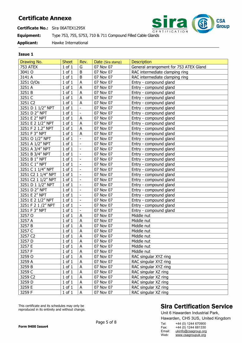
Issue 1 Drawing No. Sheet Rev. Date (Sira stamp) Description 753 ATEX 1 of 1 G 07 Nov 07 General arrangement for 753 ATEX Gland 3041 O 1 of 1 B 07 Nov 07 RAC intermediate clamping ring 3141 A 1 of 1 B 07 Nov 07 RAC intermediate clamping ring 3251 O/Os 1 of 1 A 07 Nov 07 Entry - compound gland 3251 A 1 of 1 A 07 Nov 07 Entry - compound gland 3251 B 1 of 1 A 07 Nov 07 Entry - compound gland 3251 C 1 of 1 A 07 Nov 07 Entry - compound gland 3251 C2 1 of 1 A 07 Nov 07 Entry - compound gland 3251 D 1 1/2” NPT 1 of 1 - 07 Nov 07 Entry - compound gland 3251 D 2” NPT 1 of 1 - 07 Nov 07 Entry - compound gland 3251 E 2” NPT 1 of 1 A 07 Nov 07 Entry - compound gland 3251 E 2 1/2” NPT 1 of 1 A 07 Nov 07 Entry - compound gland 3251 F 2 1.2” NPT 1 of 1 A 07 Nov 07 Entry - compound gland 3251 F 3” NPT 1 of 1 A 07 Nov 07 Entry - compound gland 3251 O 1/2” NPT 1 of 1 - 07 Nov 07 Entry - compound gland 3251 A 1/2” NPT 1 of 1 - 07 Nov 07 Entry - compound gland 3251 A 3/4” NPT 1 of 1 - 07 Nov 07 Entry - compound gland 3251 B 3/4” NPT 1 of 1 - 07 Nov 07 Entry - compound gland 3251 B 1” NPT 1 of 1 - 07 Nov 07 Entry - compound gland 3251 C 1” NPT 1 of 1 - 07 Nov 07 Entry - compound gland 3251 C 1 1/4” NPT 1 of 1 - 07 Nov 07 Entry - compound gland 3251 C2 1 1/4” NPT 1 of 1 - 07 Nov 07 Entry - compound gland 3251 C2 1 1/2” NPT 1 of 1 - 07 Nov 07 Entry - compound gland 3251 D 1 1/2” NPT 1 of 1 - 07 Nov 07 Entry - compound gland 3251 D 2” NPT 1 of 1 - 07 Nov 07 Entry - compound gland 3251 E 2” NPT 1 of 1 - 07 Nov 07 Entry - compound gland 3251 E 2 1/2” NPT 1 of 1 - 07 Nov 07 Entry - compound gland 3251 F 2 1 /2” NPT 1 of 1 - 07 Nov 07 Entry - compound gland 3251 F 3” NPT 1 of 1 - 07 Nov 07 Entry - compound gland 3257 O 1 of 1 A 07 Nov 07 Middle nut 3257 A 1 of 1 A 07 Nov 07 Middle nut 3257 B 1 of 1 A 07 Nov 07 Middle nut 3257 C 1 of 1 A 07 Nov 07 Middle nut 3257 C2 1 of 1 A 07 Nov 07 Middle nut 3257 D 1 of 1 A 07 Nov 07 Middle nut 3257 E 1 of 1 A 07 Nov 07 Middle nut 3257 F 1 of 1 A 07 Nov 07 Middle nut 3259 O 1 of 1 A 07 Nov 07 RAC singular XYZ ring 3259 A 1 of 1 A 07 Nov 07 RAC singular XYZ ring 3259 B 1 of 1 A 07 Nov 07 RAC singular XYZ ring 3259 C 1 of 1 A 07 Nov 07 RAC singular XZ ring 3259 C2 1 of 1 A 07 Nov 07 RAC singular XZ ring 3259 D 1 of 1 A 07 Nov 07 RAC singular XZ ring 3259 E 1 of 1 A 07 Nov 07 RAC singular XZ ring 3259 F 1 of 1 A 07 Nov 07 RAC singular XZ ring
Sira Certification Service Unit 6 Hawarden Industrial Park, Hawarden, CH5 3US, United Kingdom
Tel: +44 (0) 1244 670900 Fax: +44 (0) 1244 681330 Email: [email protected] Web: www.csagroupuk.org
Certificate Annexe Certificate No.: Sira 06ATEX1295X Equipment: Type 753, 755, S753, 710 & 711 Compound Filled Cable Glands Applicant: Hawke International
This certificate and its schedules may only be reproduced in its entirety and without change. Page 6 of 8 Form 9400 Issue4
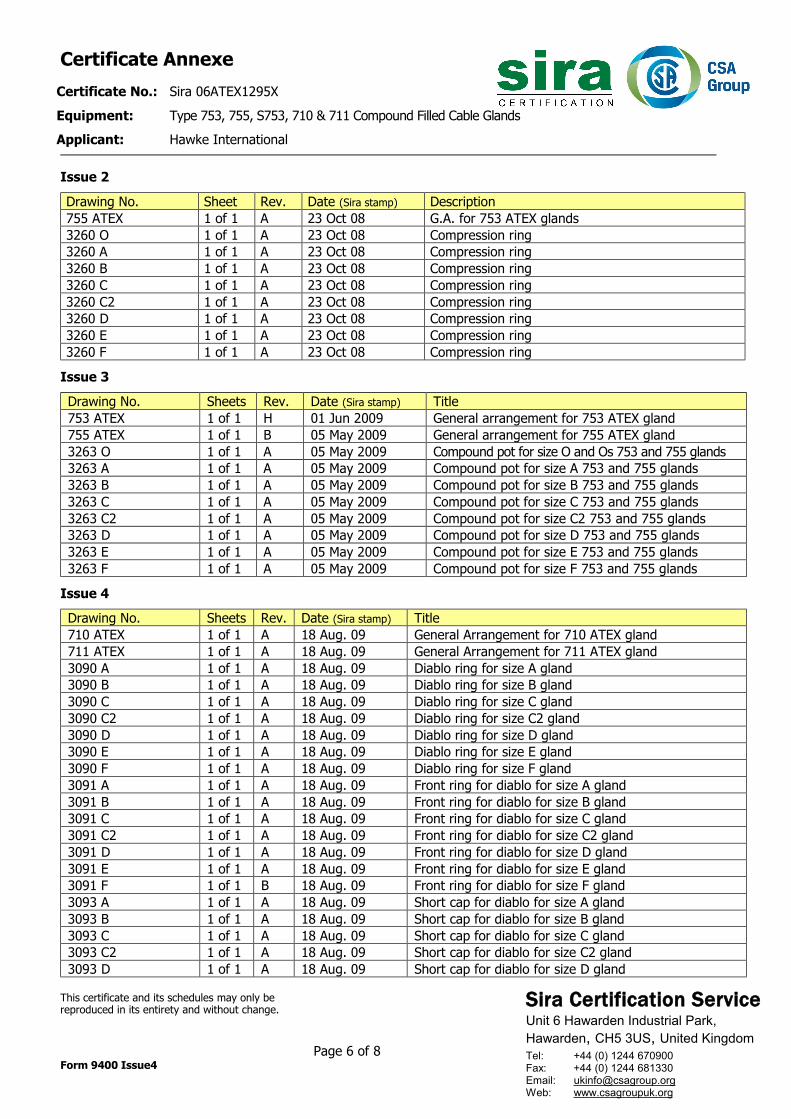
Issue 2 Drawing No. Sheet Rev. Date (Sira stamp) Description 755 ATEX 1 of 1 A 23 Oct 08 G.A. for 753 ATEX glands 3260 O 1 of 1 A 23 Oct 08 Compression ring 3260 A 1 of 1 A 23 Oct 08 Compression ring 3260 B 1 of 1 A 23 Oct 08 Compression ring 3260 C 1 of 1 A 23 Oct 08 Compression ring 3260 C2 1 of 1 A 23 Oct 08 Compression ring 3260 D 1 of 1 A 23 Oct 08 Compression ring 3260 E 1 of 1 A 23 Oct 08 Compression ring 3260 F 1 of 1 A 23 Oct 08 Compression ring
Issue 3 Drawing No. Sheets Rev. Date (Sira stamp) Title 753 ATEX 1 of 1 H 01 Jun 2009 General arrangement for 753 ATEX gland 755 ATEX 1 of 1 B 05 May 2009 General arrangement for 755 ATEX gland 3263 O 1 of 1 A 05 May 2009 Compound pot for size O and Os 753 and 755 glands 3263 A 1 of 1 A 05 May 2009 Compound pot for size A 753 and 755 glands 3263 B 1 of 1 A 05 May 2009 Compound pot for size B 753 and 755 glands 3263 C 1 of 1 A 05 May 2009 Compound pot for size C 753 and 755 glands 3263 C2 1 of 1 A 05 May 2009 Compound pot for size C2 753 and 755 glands 3263 D 1 of 1 A 05 May 2009 Compound pot for size D 753 and 755 glands 3263 E 1 of 1 A 05 May 2009 Compound pot for size E 753 and 755 glands 3263 F 1 of 1 A 05 May 2009 Compound pot for size F 753 and 755 glands
Issue 4 Drawing No. Sheets Rev. Date (Sira stamp) Title 710 ATEX 1 of 1 A 18 Aug. 09 General Arrangement for 710 ATEX gland 711 ATEX 1 of 1 A 18 Aug. 09 General Arrangement for 711 ATEX gland 3090 A 1 of 1 A 18 Aug. 09 Diablo ring for size A gland 3090 B 1 of 1 A 18 Aug. 09 Diablo ring for size B gland 3090 C 1 of 1 A 18 Aug. 09 Diablo ring for size C gland 3090 C2 1 of 1 A 18 Aug. 09 Diablo ring for size C2 gland 3090 D 1 of 1 A 18 Aug. 09 Diablo ring for size D gland 3090 E 1 of 1 A 18 Aug. 09 Diablo ring for size E gland 3090 F 1 of 1 A 18 Aug. 09 Diablo ring for size F gland 3091 A 1 of 1 A 18 Aug. 09 Front ring for diablo for size A gland 3091 B 1 of 1 A 18 Aug. 09 Front ring for diablo for size B gland 3091 C 1 of 1 A 18 Aug. 09 Front ring for diablo for size C gland 3091 C2 1 of 1 A 18 Aug. 09 Front ring for diablo for size C2 gland 3091 D 1 of 1 A 18 Aug. 09 Front ring for diablo for size D gland 3091 E 1 of 1 A 18 Aug. 09 Front ring for diablo for size E gland 3091 F 1 of 1 B 18 Aug. 09 Front ring for diablo for size F gland 3093 A 1 of 1 A 18 Aug. 09 Short cap for diablo for size A gland 3093 B 1 of 1 A 18 Aug. 09 Short cap for diablo for size B gland 3093 C 1 of 1 A 18 Aug. 09 Short cap for diablo for size C gland 3093 C2 1 of 1 A 18 Aug. 09 Short cap for diablo for size C2 gland 3093 D 1 of 1 A 18 Aug. 09 Short cap for diablo for size D gland
Sira Certification Service Unit 6 Hawarden Industrial Park, Hawarden, CH5 3US, United Kingdom
Tel: +44 (0) 1244 670900 Fax: +44 (0) 1244 681330 Email: [email protected] Web: www.csagroupuk.org
Certificate Annexe Certificate No.: Sira 06ATEX1295X Equipment: Type 753, 755, S753, 710 & 711 Compound Filled Cable Glands Applicant: Hawke International
This certificate and its schedules may only be reproduced in its entirety and without change. Page 7 of 8 Form 9400 Issue4
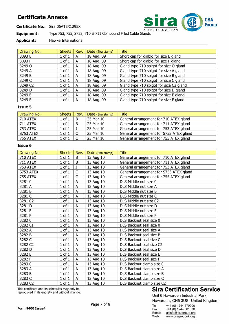
Drawing No. Sheets Rev. Date (Sira stamp) Title 3093 E 1 of 1 A 18 Aug. 09 Short cap for diablo for size E gland 3093 F 1 of 1 A 18 Aug. 09 Short cap for diablo for size F gland 3249 O 1 of 1 A 18 Aug. 09 Gland type 710 spigot for size O gland 3249 A 1 of 1 A 18 Aug. 09 Gland type 710 spigot for size A gland 3249 B 1 of 1 A 18 Aug. 09 Gland type 710 spigot for size B gland 3249 C 1 of 1 A 18 Aug. 09 Gland type 710 spigot for size C gland 3249 C2 1 of 1 A 18 Aug. 09 Gland type 710 spigot for size C2 gland 3249 D 1 of 1 A 18 Aug. 09 Gland type 710 spigot for size D gland 3249 E 1 of 1 A 18 Aug. 09 Gland type 710 spigot for size E gland 3249 F 1 of 1 A 18 Aug. 09 Gland type 710 spigot for size F gland
Issue 5 Drawing No. Sheets Rev. Date (Sira stamp) Title 710 ATEX 1 of 1 B 25 Mar 10 General arrangement for 710 ATEX gland 711 ATEX 1 of 1 B 25 Mar 10 General arrangement for 711 ATEX gland 753 ATEX 1 of 1 J 25 Mar 10 General arrangement for 753 ATEX gland S753 ATEX 1 of 1 C 25 Mar 10 General arrangement for S753 ATEX gland 755 ATEX 1 of 1 C 25 Mar 10 General arrangement for 755 ATEX gland
Issue 6 Drawing No. Sheets Rev. Date (Sira stamp) Title 710 ATEX 1 of 1 B 13 Aug 10 General arrangement for 710 ATEX gland 711 ATEX 1 of 1 B 13 Aug 10 General arrangement for 711 ATEX gland 753 ATEX 1 of 1 J 13 Aug 10 General arrangement for 753 ATEX gland S753 ATEX 1 of 1 C 13 Aug 10 General arrangement for S753 ATEX gland 755 ATEX 1 of 1 C 13 Aug 10 General arrangement for 755 ATEX gland 3281 0 1 of 1 A 13 Aug 10 DLS Middle nut size 0 3281 A 1 of 1 A 13 Aug 10 DLS Middle nut size A 3281 B 1 of 1 A 13 Aug 10 DLS Middle nut size B 3281 C 1 of 1 A 13 Aug 10 DLS Middle nut size C 3281 C2 1 of 1 A 13 Aug 10 DLS Middle nut size C2 3281 D 1 of 1 A 13 Aug 10 DLS Middle nut size D 3281 E 1 of 1 A 13 Aug 10 DLS Middle nut size E 3281 F 1 of 1 A 13 Aug 10 DLS Middle nut size F 3282 0 1 of 1 A 13 Aug 10 DLS Backnut seal size 0 3282 0s 1 of 1 A 13 Aug 10 DLS Backnut seal size 0 3282 A 1 of 1 A 13 Aug 10 DLS Backnut seal size A 3282 B 1 of 1 A 13 Aug 10 DLS Backnut seal size B 3282 C 1 of 1 A 13 Aug 10 DLS Backnut seal size C 3282 C2 1 of 1 A 13 Aug 10 DLS Backnut seal size C2 3282 D 1 of 1 A 13 Aug 10 DLS Backnut seal size D 3282 E 1 of 1 A 13 Aug 10 DLS Backnut seal size E 3282 F 1 of 1 A 13 Aug 10 DLS Backnut seal size F 3283 0 1 of 1 A 13 Aug 10 DLS Backnut clamp size 0 3283 A 1 of 1 A 13 Aug 10 DLS Backnut clamp size A 3283 B 1 of 1 A 13 Aug 10 DLS Backnut clamp size B 3283 C 1 of 1 A 13 Aug 10 DLS Backnut clamp size C 3283 C2 1 of 1 A 13 Aug 10 DLS Backnut clamp size C2
Sira Certification Service Unit 6 Hawarden Industrial Park, Hawarden, CH5 3US, United Kingdom
Tel: +44 (0) 1244 670900 Fax: +44 (0) 1244 681330 Email: [email protected] Web: www.csagroupuk.org
Certificate Annexe Certificate No.: Sira 06ATEX1295X Equipment: Type 753, 755, S753, 710 & 711 Compound Filled Cable Glands Applicant: Hawke International
This certificate and its schedules may only be reproduced in its entirety and without change. Page 8 of 8 Form 9400 Issue4
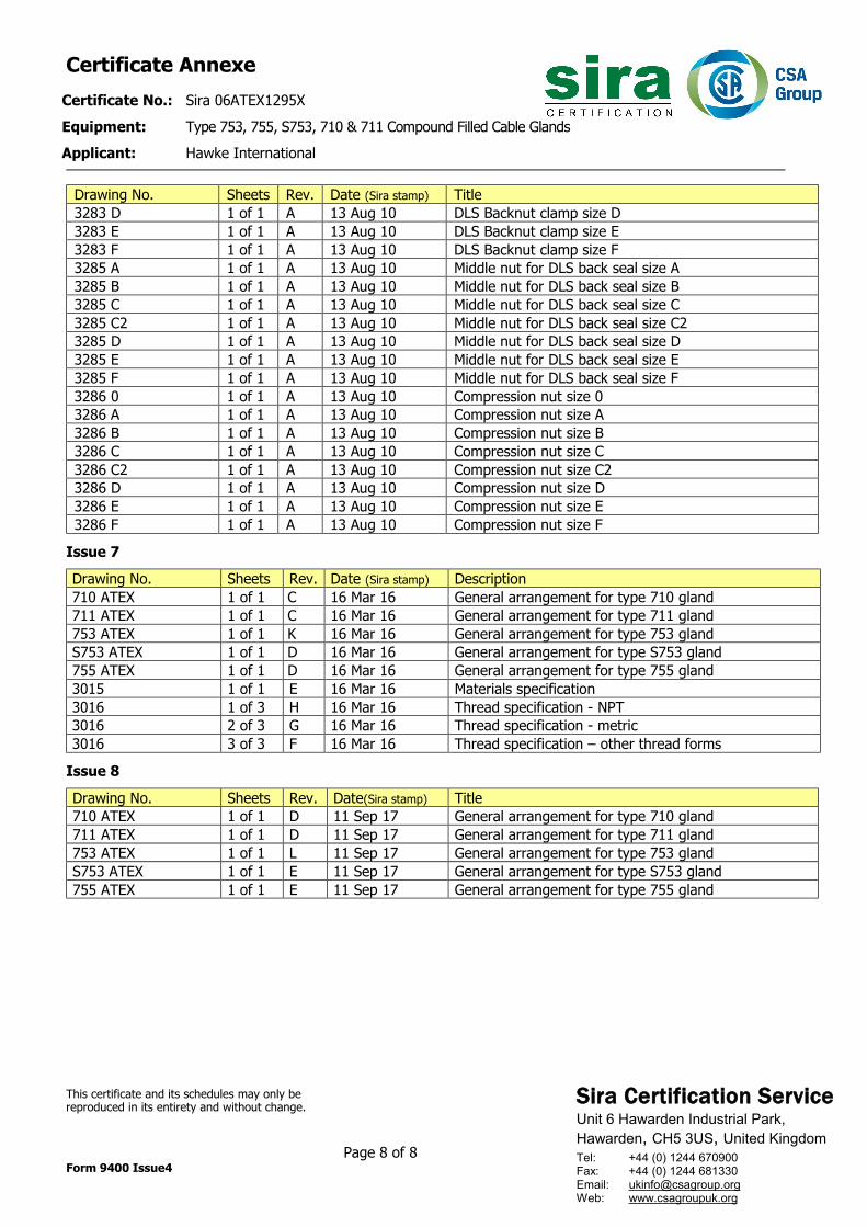
Drawing No. Sheets Rev. Date (Sira stamp) Title 3283 D 1 of 1 A 13 Aug 10 DLS Backnut clamp size D 3283 E 1 of 1 A 13 Aug 10 DLS Backnut clamp size E 3283 F 1 of 1 A 13 Aug 10 DLS Backnut clamp size F 3285 A 1 of 1 A 13 Aug 10 Middle nut for DLS back seal size A 3285 B 1 of 1 A 13 Aug 10 Middle nut for DLS back seal size B 3285 C 1 of 1 A 13 Aug 10 Middle nut for DLS back seal size C 3285 C2 1 of 1 A 13 Aug 10 Middle nut for DLS back seal size C2 3285 D 1 of 1 A 13 Aug 10 Middle nut for DLS back seal size D 3285 E 1 of 1 A 13 Aug 10 Middle nut for DLS back seal size E 3285 F 1 of 1 A 13 Aug 10 Middle nut for DLS back seal size F 3286 0 1 of 1 A 13 Aug 10 Compression nut size 0 3286 A 1 of 1 A 13 Aug 10 Compression nut size A 3286 B 1 of 1 A 13 Aug 10 Compression nut size B 3286 C 1 of 1 A 13 Aug 10 Compression nut size C 3286 C2 1 of 1 A 13 Aug 10 Compression nut size C2 3286 D 1 of 1 A 13 Aug 10 Compression nut size D 3286 E 1 of 1 A 13 Aug 10 Compression nut size E 3286 F 1 of 1 A 13 Aug 10 Compression nut size F
Issue 7 Drawing No. Sheets Rev. Date (Sira stamp) Description 710 ATEX 1 of 1 C 16 Mar 16 General arrangement for type 710 gland 711 ATEX 1 of 1 C 16 Mar 16 General arrangement for type 711 gland 753 ATEX 1 of 1 K 16 Mar 16 General arrangement for type 753 gland S753 ATEX 1 of 1 D 16 Mar 16 General arrangement for type S753 gland 755 ATEX 1 of 1 D 16 Mar 16 General arrangement for type 755 gland 3015 1 of 1 E 16 Mar 16 Materials specification 3016 1 of 3 H 16 Mar 16 Thread specification - NPT 3016 2 of 3 G 16 Mar 16 Thread specification - metric 3016 3 of 3 F 16 Mar 16 Thread specification – other thread forms
Issue 8 Drawing No. Sheets Rev. Date(Sira stamp) Title 710 ATEX 1 of 1 D 11 Sep 17 General arrangement for type 710 gland 711 ATEX 1 of 1 D 11 Sep 17 General arrangement for type 711 gland 753 ATEX 1 of 1 L 11 Sep 17 General arrangement for type 753 gland S753 ATEX 1 of 1 E 11 Sep 17 General arrangement for type S753 gland 755 ATEX 1 of 1 E 11 Sep 17 General arrangement for type 755 gland