Embed Size (px)
Citation preview

© 2011 PHOENIX CONTACT
EtherNet/IP™: When to Go Wireless
White Paper Presented by: Justin Shade Product Marketing Specialist – Wireless and Bob Licata Senior Applications Engineer Phoenix Contact USA P.O. Box 4100 Harrisburg, PA 17111-0001 717-944-1300 www.phoenixcontact.com
1
PHOENIX CONTACT • P.O. Box 4100 • Harrisburg, PA 17111-0001
717-944-1300 • Fax: 717-944-1625 • e-mail: [email protected] • www.phoenixcontact.com © 2011 PHOENIX CONTACT
EtherNet/IP™: When to Go Wireless Key concepts:
EtherNet/IP™ is becoming increasingly common in industrial applications
In many cases, a wireless EtherNet/IP network makes more sense than a hard-wired network
EtherNet/IP can work over various wireless networks, but for a successful installation, consider: o The bandwidth limitations of the network o The amount of data being communicated o Explicit versus implicit messaging can work better, especially for communication that are
not time-critical
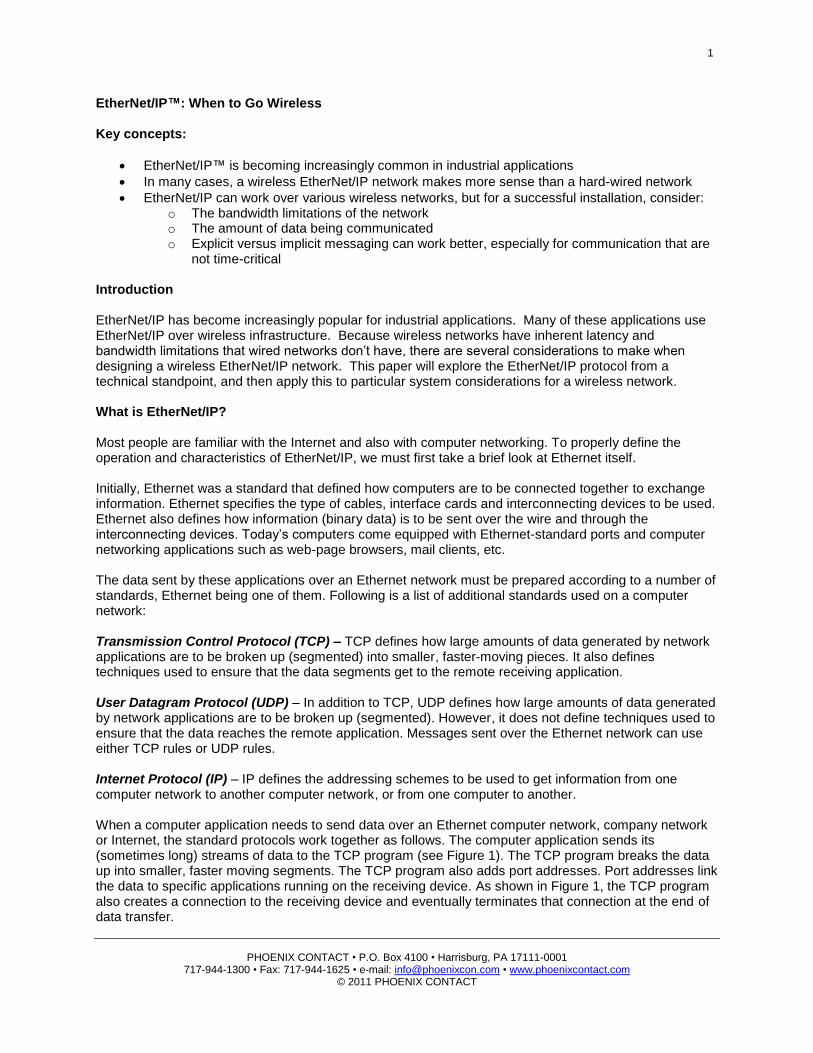
Introduction EtherNet/IP has become increasingly popular for industrial applications. Many of these applications use EtherNet/IP over wireless infrastructure. Because wireless networks have inherent latency and bandwidth limitations that wired networks don’t have, there are several considerations to make when designing a wireless EtherNet/IP network. This paper will explore the EtherNet/IP protocol from a technical standpoint, and then apply this to particular system considerations for a wireless network. What is EtherNet/IP? Most people are familiar with the Internet and also with computer networking. To properly define the operation and characteristics of EtherNet/IP, we must first take a brief look at Ethernet itself. Initially, Ethernet was a standard that defined how computers are to be connected together to exchange information. Ethernet specifies the type of cables, interface cards and interconnecting devices to be used. Ethernet also defines how information (binary data) is to be sent over the wire and through the interconnecting devices. Today’s computers come equipped with Ethernet-standard ports and computer networking applications such as web-page browsers, mail clients, etc. The data sent by these applications over an Ethernet network must be prepared according to a number of standards, Ethernet being one of them. Following is a list of additional standards used on a computer network: Transmission Control Protocol (TCP) – TCP defines how large amounts of data generated by network applications are to be broken up (segmented) into smaller, faster-moving pieces. It also defines techniques used to ensure that the data segments get to the remote receiving application. User Datagram Protocol (UDP) – In addition to TCP, UDP defines how large amounts of data generated by network applications are to be broken up (segmented). However, it does not define techniques used to ensure that the data reaches the remote application. Messages sent over the Ethernet network can use either TCP rules or UDP rules. Internet Protocol (IP) – IP defines the addressing schemes to be used to get information from one computer network to another computer network, or from one computer to another. When a computer application needs to send data over an Ethernet computer network, company network or Internet, the standard protocols work together as follows. The computer application sends its (sometimes long) streams of data to the TCP program (see Figure 1). The TCP program breaks the data up into smaller, faster moving segments. The TCP program also adds port addresses. Port addresses link the data to specific applications running on the receiving device. As shown in Figure 1, the TCP program also creates a connection to the receiving device and eventually terminates that connection at the end of data transfer.
2
PHOENIX CONTACT • P.O. Box 4100 • Harrisburg, PA 17111-0001
717-944-1300 • Fax: 717-944-1625 • e-mail: [email protected] • www.phoenixcontact.com © 2011 PHOENIX CONTACT
Figure 1: Ethernet data transmitted through TCP protocol
The IP program adds network IP addresses. The IP addresses enable the data segment to get from one computer to another computer, or from one network of computers to another network of computers. Finally, the Ethernet standard network interface card (NIC) adds its own address, called the media access address (MAC), and the MAC of the card the data is going to. This final packet of information, referred to as an Ethernet frame, is approximately 1526 bytes long. Of that, 1394 to 1474 bytes could be actual application data. The frames of data are then sent sequentially to the receiving computer. The same protocols on the receiving computer put all the segments back together again and passes the stream of data to the receiving application. We have seen that the IP program and the Ethernet NIC add addressing information to an Ethernet frame. These addresses can be one of three types: Unicast – When a unicast address is added to an Ethernet frame, that frame travels from one sending device to one receiving device. Standard Ethernet switches (assuming switches are being used) will route unicast packets to the single receiver. The responses will also be routed back to the sender only. Other devices on the network will not have to process the frame. Broadcast – When a broadcast address is added to an Ethernet frame, that frame travels from one sending device to all devices on the Ethernet network. All devices on the network must read the frame in and process it. Broadcast frames are broadcast out of all ports of a standard Ethernet switch. Multicast – When a multicast address is added to an Ethernet frame, that frame travels from one device to a group of devices on the network. The group of devices is referred to as a multicast group. All devices in this group, must process the frame. Multicast frames are also broadcast out of all ports of a standard Ethernet switch. Recently, industrial PLCs and field I/O devices have incorporated the Ethernet standards. PLCs can communicate to other PLCs or to field I/O devices using Ethernet cables and Ethernet interconnecting devices such as hubs, switches and routers. EtherNet/IP is an application that runs on a PLC or an EtherNet/IP field I/O device. The data produced by the EtherNet/IP application is sent to the stack of Ethernet protocols, as previously discussed. Instead of the data portion of the Ethernet frame being e-mail data or web-page data, it is field I/O data. EtherNet/IP devices use all of the Ethernet standard cables and interconnecting devices to communicate. EtherNet/IP devices use either TCP or UDP to segment the I/O data. They also use both unicast and multicast addresses.
Added by Ethernet standard networking interface card (NIC)
IP program
Network Addressing Information
Application data consisting of binary code (100010001111001110011, etc.)
TCP or UDP program
Data Segment
Port Data Segment
Port Data Segment
Port
Data Segment
Port
Network Addressing Information
Data Segment
Port Actual computer card address
Final data frame that is sent
Datagram, which consists of one data segment and a port address
3
PHOENIX CONTACT • P.O. Box 4100 • Harrisburg, PA 17111-0001
717-944-1300 • Fax: 717-944-1625 • e-mail: [email protected] • www.phoenixcontact.com © 2011 PHOENIX CONTACT
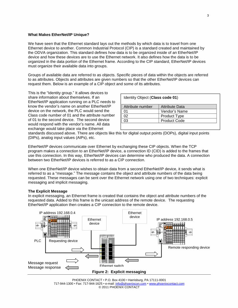
Identity Object (Class code 01)
Attribute number Attribute Data
01 Vendor’s Name
02 Product Type
03 Product Code
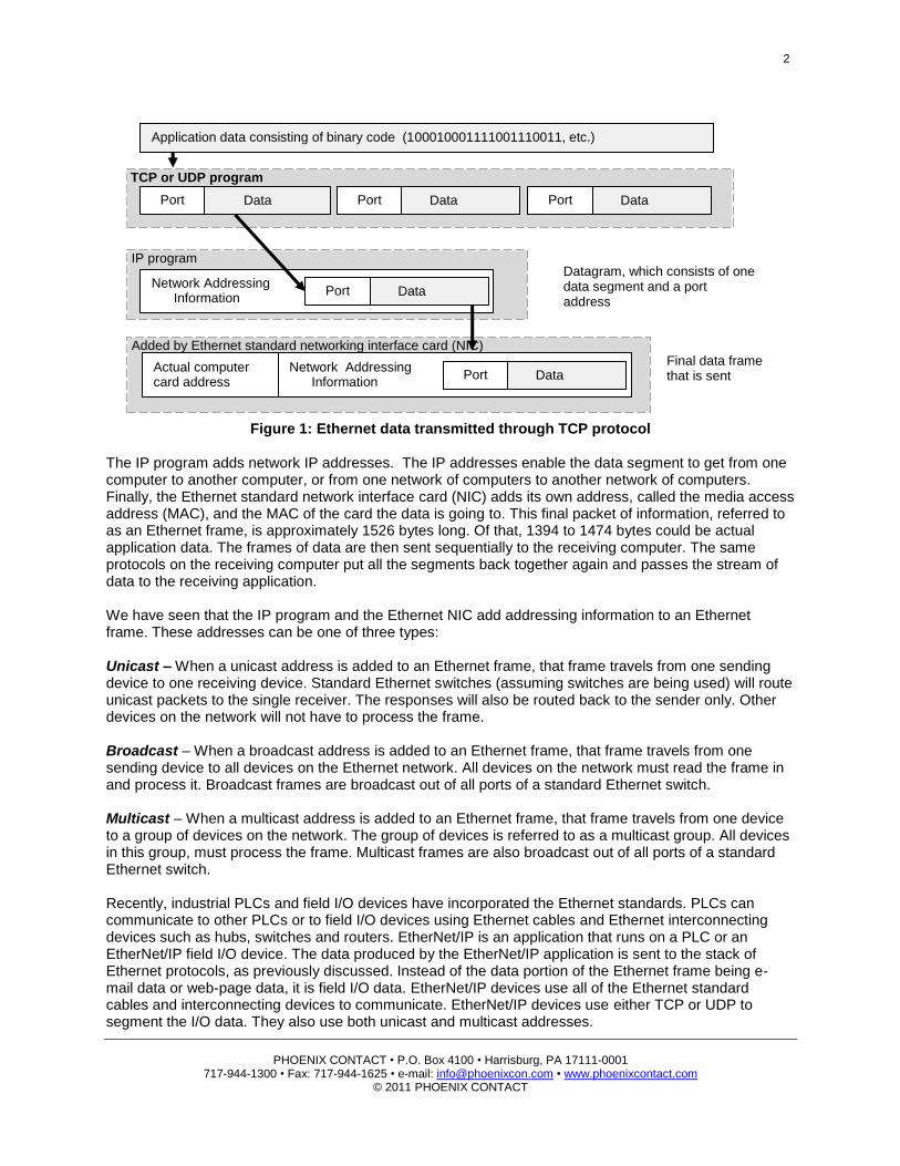
What Makes EtherNet/IP Unique? We have seen that the Ethernet standard lays out the methods by which data is to travel from one Ethernet device to another. Common Industrial Protocol (CIP) is a standard created and maintained by the ODVA organization. This standard defines how data is to be organized inside of an EtherNet/IP device and how these devices are to use the Ethernet network. It also defines how the data is to be organized in the data portion of the Ethernet frame. According to the CIP standard, EtherNet/IP devices must organize their available data into groups. Groups of available data are referred to as objects. Specific pieces of data within the objects are referred to as attributes. Objects and attributes are given numbers so that the other EtherNet/IP devices can request them. Below is an example of a CIP object and some of its attributes. This is the “Identity group.” It allows devices to share information about themselves. If an EtherNet/IP application running on a PLC needs to know the vendor’s name on another EtherNet/IP device on the network, the PLC would send the Class code number of 01 and the attribute number of 01 to the second device. The second device would respond with the vendor’s name. All data exchange would take place via the Ethernet standards discussed above. There are objects like this for digital output points (DOPs), digital input points (DIPs), analog input values (AIPs), etc. EtherNet/IP devices communicate over Ethernet by exchanging these CIP objects. When the TCP program makes a connection to an EtherNet/IP device, a connection ID (CID) is added to the frames that use this connection. In this way, EtherNet/IP devices can determine who produced the data. A connection between two EtherNet/IP devices is referred to as a CIP connection. When one EtherNet/IP device wishes to obtain data from a second EtherNet/IP device, it sends what is referred to as a “message.” The message contains the object and attribute numbers of the data being requested. These messages can be sent over the Ethernet network using one of two techniques: explicit messaging and implicit messaging. The Explicit Message In explicit messaging, an Ethernet frame is created that contains the object and attribute numbers of the requested data. Added to this frame is the unicast address of the remote device. The requesting EtherNet/IP application then creates a CIP connection to the remote device. Message request Message response
Figure 2: Explicit messaging
IP address 192.168.0.4
PLC Requesting device
Ethernet switch
IP address 192.168.0.5
Remote responding device
Ethernet device
Ethernet device
4
PHOENIX CONTACT • P.O. Box 4100 • Harrisburg, PA 17111-0001
717-944-1300 • Fax: 717-944-1625 • e-mail: [email protected] • www.phoenixcontact.com © 2011 PHOENIX CONTACT
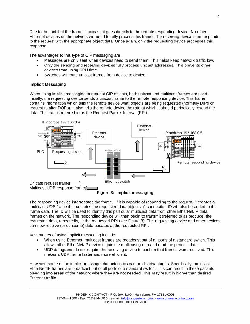
Due to the fact that the frame is unicast, it goes directly to the remote responding device. No other Ethernet devices on the network will need to fully process this frame. The receiving device then responds to the request with the appropriate object data. Once again, only the requesting device processes this response. The advantages to this type of CIP messaging are:
Messages are only sent when devices need to send them. This helps keep network traffic low.
Only the sending and receiving devices fully process unicast addresses. This prevents other devices from using CPU time.
Switches will route unicast frames from device to device. Implicit Messaging When using implicit messaging to request CIP objects, both unicast and multicast frames are used. Initially, the requesting device sends a unicast frame to the remote responding device. This frame contains information which tells the remote device what objects are being requested (normally DIPs or request to alter DOPs). It also tells the remote device the rate at which it should periodically resend the data. This rate is referred to as the Request Packet Interval (RPI). Unicast request frame Multicast UDP response frames
Figure 3: Implicit messaging The responding device interrogates the frame. If it is capable of responding to the request, it creates a multicast UDP frame that contains the requested data objects. A connection ID will also be added to the frame data. The ID will be used to identify this particular multicast data from other EtherNet/IP data frames on the network. The responding device will then begin to transmit (referred to as produce) the requested data, repeatedly, at the requested RPI (see Figure 3). The requesting device and other devices can now receive (or consume) data updates at the requested RPI. Advantages of using implicit messaging include:
When using Ethernet, multicast frames are broadcast out of all ports of a standard switch. This allows other EtherNet/IP device to join the multicast group and read the periodic data.
UDP datagrams do not require the receiving device to confirm that frames were received. This makes a UDP frame faster and more efficient.
However, some of the implicit message characteristics can be disadvantages. Specifically, multicast EtherNet/IP frames are broadcast out of all ports of a standard switch. This can result in these packets bleeding into areas of the network where they are not needed. This may result in higher than desired Ethernet traffic.
Ethernet switch
IP address 192.168.0.5
Remote responding device
Ethernet device
IP address 192.168.0.4
PLC Requesting device
Ethernet device
5
PHOENIX CONTACT • P.O. Box 4100 • Harrisburg, PA 17111-0001
717-944-1300 • Fax: 717-944-1625 • e-mail: [email protected] • www.phoenixcontact.com © 2011 PHOENIX CONTACT
Explicit or Implicit? In most PLCs, explicit messaging requires the programmer to create a special request block. This block typically includes the object and attribute numbers and some additional information. The block is then triggered as needed. This type of communication does not load the network with continuous responses. Explicit message blocks can be used for obtaining configuration information from a device or for configuring a device. They can also be used for obtaining I/O data, DIPs, DOPs, etc. They are also advantageous in slower, high-traffic networks. When using implicit messaging, programmers normally give the PLC something called an “assembly instance.” They also tell the PLC that they would like to read a specified amount of DIPs and write a specified amount of DOPs at a specified RPI. The implicit form of communication does not require triggering. As discussed earlier, the responding device(s) will multicast data at the specified RPI. Implicit messages can be used when more than one EtherNet/IP device will be receiving the same data. It can also be used along with low traffic networks for rapid data transfer. Due to the nature of multicasting, implicit messaging could cause problems on lower-speed networks. Implicit messaging is deterministic. This means it is possible to estimate the data’s travel rate. When using implicit messaging on anything other than an excellent-performing network, it is a good idea to estimate the number of packets that will travel the network per second. Implicit messaging is normally used to obtain field I/O status. We mentioned earlier that an Ethernet frame, under worst cases, could contain about 1.3 kilobytes (KB) of application data. This results in approximately 650 words of data. Therefore, we can assume that all of the requested data can be returned in one frame or packet. To estimate the data rate, you will need to know the number of CIP connections in the network. Normally, each EtherNet/IP device communicating with the EtherNet/IP scanner occupies a single CIP connection. Since the implicit connection is bidirectional, we would then multiply the number of connections by two, and then divide this product by a desired RPI. Assume there are eight EtherNet/IP field I/O devices connected to a single PLC scanner, and you desire an RPI rate of 25 milliseconds (ms). The data rate would be estimated as follows: [(CIP connections) X 2]/RPI = (8 X 2)/.025 = 640 pps (packets/frames per second) Why Wireless EtherNet/IP? When planning a network installation, running wires is typically the ideal technique because of the benefits that come with that wired connection. When specifically talking about EtherNet/IP, the main benefit is the network speed capability. A wired EtherNet/IP network can transmit much more data, much more efficiently, than a wireless EtherNet/IP network. So, why would you choose to install a wireless system instead of a wired one? Wireless also offers many network installation benefits. The biggest advantage is the cost of the installation itself. Running cables can cost the user anywhere from $20 to $2,000 per foot, depending on the environment and labor costs. Once those costs are calculated, you also need to take into account the number of man hours the job requires. Not only are you paying for the materials, you are also losing valuable time in man hours as the installers run the wires. Another benefit to running a wireless EtherNet/IP network is the reliability of the network. A wireless system has fewer possible points of failure. This means, if it is implemented correctly, it can be much more reliable. Further, a damaged or broken cable during normal operation can lead to downtime and the additional cost of fixing those wires. Lastly, a wireless system offers electrical isolation, eliminating potential surge damage common in a wired system.
6
PHOENIX CONTACT • P.O. Box 4100 • Harrisburg, PA 17111-0001
717-944-1300 • Fax: 717-944-1625 • e-mail: [email protected] • www.phoenixcontact.com © 2011 PHOENIX CONTACT
Limitations of Wireless Versus a Wired EtherNet/IP network Different aspects of an EtherNet/IP network must be taken into consideration when designing a wireless network. It should be understood that in most cases, a wired system can accommodate higher data rates than a wireless system. However, if designed properly, a wireless system can work very reliably and offer many advantages over a wired system. When designing a wireless EtherNet/IP system, you need to consider several specific factors. The first question is: which type of wireless technology is best suited for this job? The faster wireless technology is not always the correct technology. If the application does not require high rate data transfer, a frequency-hopping wireless technology may be the better choice. Frequency-hopping increases robustness and can communicate through high interference areas. Examples of some applications for the use of frequency-hopping technology would be:
Sharing periodic information between PLCs in which update times of 200 ms or less are acceptable
Connecting HMI panels to remote devices
Using remote SCADA systems
None of the above applications are typically time-sensitive or mission critical. These communications are typically messages that require slower update times. For wireless applications that require faster communication, a faster wireless technology, such as orthogonal frequency-division multiplexing (OFDM) may work better. OFDM (found in the 802.11(a) and 802.11(g) radio modes of operation) is ideal if the application requires a higher data rate or quicker update times, or requires that some type of handheld device be added to the network (e.g., laptop, PDA, etc.). Next, consider the type of messaging the application will use. When programming PLCs for EtherNet/IP communication, the programmer normally has the option of communicating via explicit messaging or implicit messaging. As mentioned in the “What Makes EtherNet/IP Unique” section, explicit messages are asynchronous messages that mainly use unicast TCP frames transmitted as needed. Explicit messaging is better suited for information that is not time-critical. Implicit messaging, as discussed earlier, is synchronous. Messages are transmitted based on an RPI rate adjusted by the programmer. Implicit frames are mainly multicast UDP packets. Not only are these types of packets broadcast by all switched ports, they are also broadcast by all radios in a group. Implicit messaging over a wireless network introduces the possibility of flooding the network with broadcast messages (multicast traffic). When implicit messaging is required, you must consider the RPI rate. One solution is to strategically locate managed switches capable of IGMP snooping around the network. Managed switches can direct multicast packets to only those devices requesting them. As discussed earlier, the RPI dictates the rate at which the multicast packets will traverse the network. Because these implicit messages are scheduled requests, it is possible to predict the packet rate on the network and configure the network accordingly. The following examples demonstrate how both explicit and implicit messages traverse a network that contains a wireless component. We will also compare IGMP managed switches with unmanaged switches.
7
PHOENIX CONTACT • P.O. Box 4100 • Harrisburg, PA 17111-0001
717-944-1300 • Fax: 717-944-1625 • e-mail: [email protected] • www.phoenixcontact.com © 2011 PHOENIX CONTACT
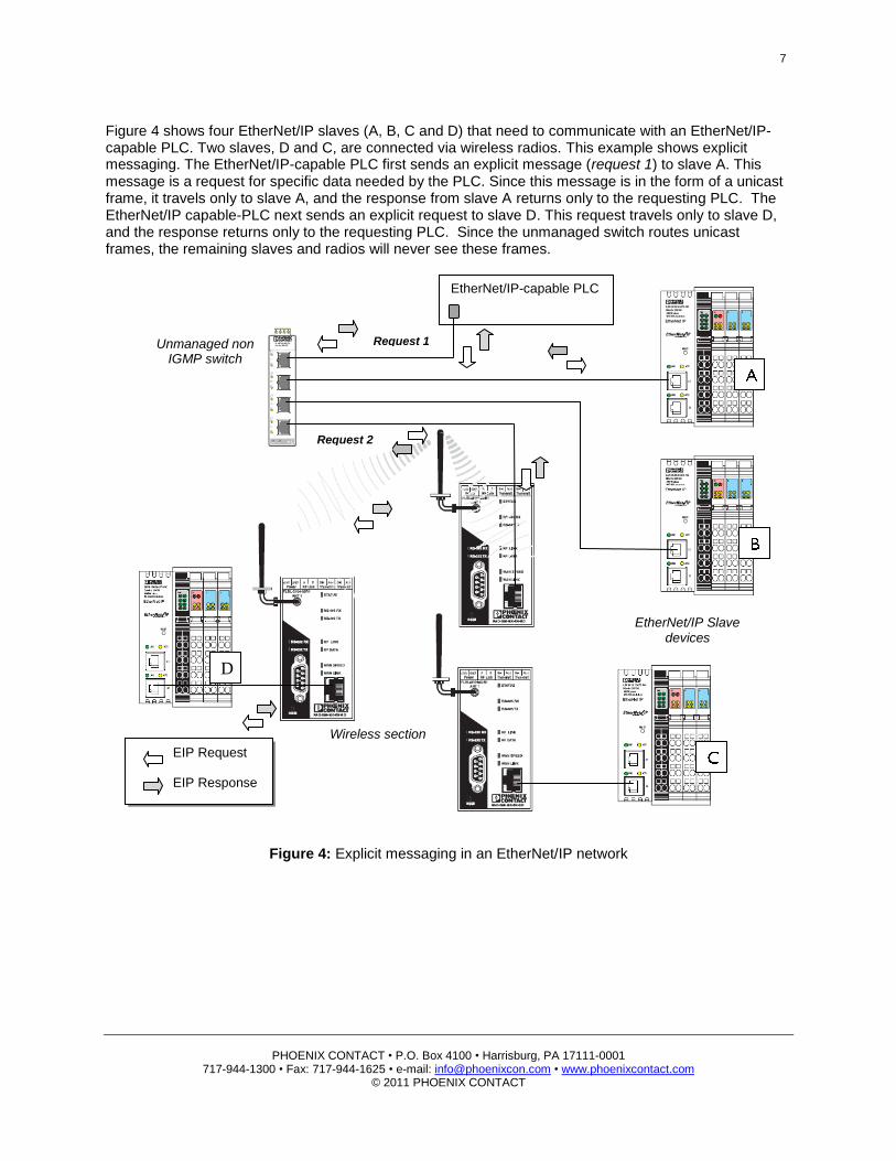
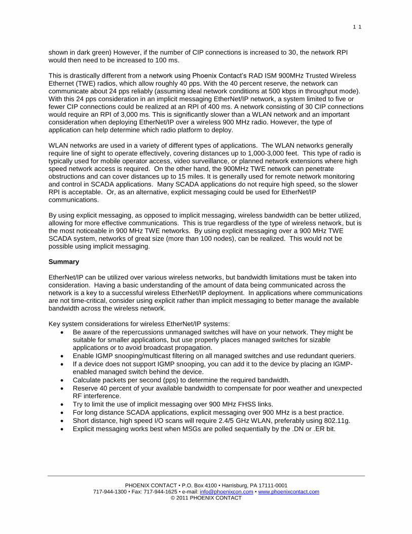
Figure 4 shows four EtherNet/IP slaves (A, B, C and D) that need to communicate with an EtherNet/IP-capable PLC. Two slaves, D and C, are connected via wireless radios. This example shows explicit messaging. The EtherNet/IP-capable PLC first sends an explicit message (request 1) to slave A. This message is a request for specific data needed by the PLC. Since this message is in the form of a unicast frame, it travels only to slave A, and the response from slave A returns only to the requesting PLC. The EtherNet/IP capable-PLC next sends an explicit request to slave D. This request travels only to slave D, and the response returns only to the requesting PLC. Since the unmanaged switch routes unicast frames, the remaining slaves and radios will never see these frames.
Figure 4: Explicit messaging in an EtherNet/IP network
EIP Request EIP Response
EtherNet/IP-capable PLC
Unmanaged non IGMP switch
EtherNet/IP Slave devices
D
Request 1
Request 2
Wireless section
8
PHOENIX CONTACT • P.O. Box 4100 • Harrisburg, PA 17111-0001
717-944-1300 • Fax: 717-944-1625 • e-mail: [email protected] • www.phoenixcontact.com © 2011 PHOENIX CONTACT
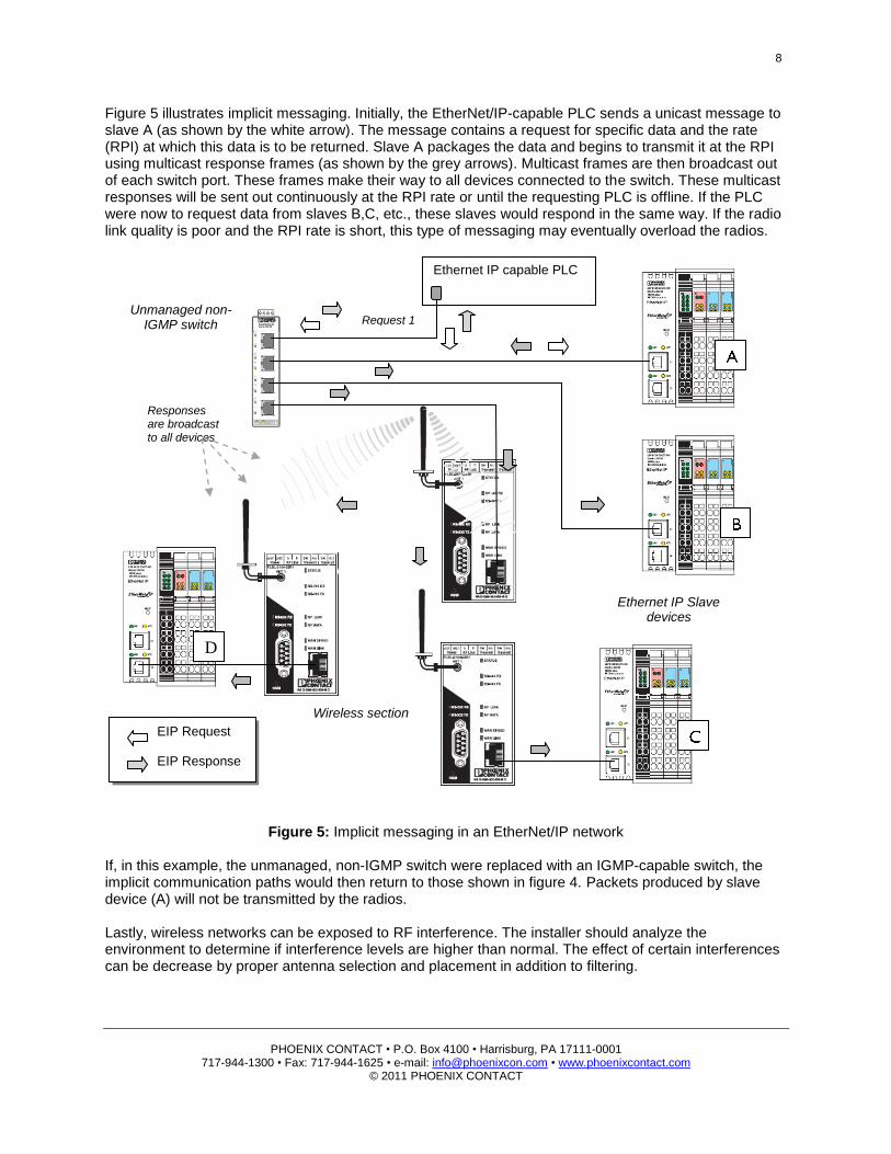
Figure 5 illustrates implicit messaging. Initially, the EtherNet/IP-capable PLC sends a unicast message to slave A (as shown by the white arrow). The message contains a request for specific data and the rate (RPI) at which this data is to be returned. Slave A packages the data and begins to transmit it at the RPI using multicast response frames (as shown by the grey arrows). Multicast frames are then broadcast out of each switch port. These frames make their way to all devices connected to the switch. These multicast responses will be sent out continuously at the RPI rate or until the requesting PLC is offline. If the PLC were now to request data from slaves B,C, etc., these slaves would respond in the same way. If the radio link quality is poor and the RPI rate is short, this type of messaging may eventually overload the radios.
Figure 5: Implicit messaging in an EtherNet/IP network
If, in this example, the unmanaged, non-IGMP switch were replaced with an IGMP-capable switch, the implicit communication paths would then return to those shown in figure 4. Packets produced by slave device (A) will not be transmitted by the radios. Lastly, wireless networks can be exposed to RF interference. The installer should analyze the environment to determine if interference levels are higher than normal. The effect of certain interferences can be decrease by proper antenna selection and placement in addition to filtering.
EIP Request EIP Response
Ethernet IP capable PLC
Unmanaged non-IGMP switch
Ethernet IP Slave devices
D
Request 1
Wireless section
Responses are broadcast to all devices
9
PHOENIX CONTACT • P.O. Box 4100 • Harrisburg, PA 17111-0001
717-944-1300 • Fax: 717-944-1625 • e-mail: [email protected] • www.phoenixcontact.com © 2011 PHOENIX CONTACT
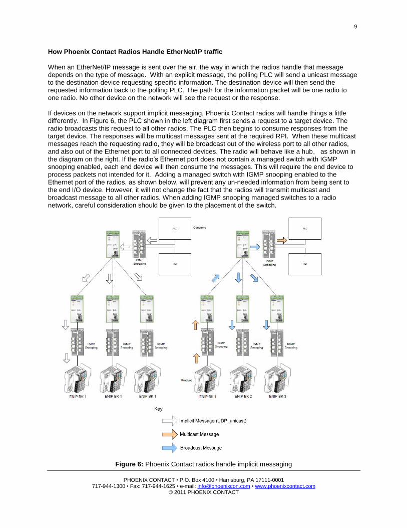
How Phoenix Contact Radios Handle EtherNet/IP traffic When an EtherNet/IP message is sent over the air, the way in which the radios handle that message depends on the type of message. With an explicit message, the polling PLC will send a unicast message to the destination device requesting specific information. The destination device will then send the requested information back to the polling PLC. The path for the information packet will be one radio to one radio. No other device on the network will see the request or the response. If devices on the network support implicit messaging, Phoenix Contact radios will handle things a little differently. In Figure 6, the PLC shown in the left diagram first sends a request to a target device. The radio broadcasts this request to all other radios. The PLC then begins to consume responses from the target device. The responses will be multicast messages sent at the required RPI. When these multicast messages reach the requesting radio, they will be broadcast out of the wireless port to all other radios, and also out of the Ethernet port to all connected devices. The radio will behave like a hub, as shown in the diagram on the right. If the radio’s Ethernet port does not contain a managed switch with IGMP snooping enabled, each end device will then consume the messages. This will require the end device to process packets not intended for it. Adding a managed switch with IGMP snooping enabled to the Ethernet port of the radios, as shown below, will prevent any un-needed information from being sent to the end I/O device. However, it will not change the fact that the radios will transmit multicast and broadcast message to all other radios. When adding IGMP snooping managed switches to a radio network, careful consideration should be given to the placement of the switch.
Figure 6: Phoenix Contact radios handle implicit messaging
1 0
PHOENIX CONTACT • P.O. Box 4100 • Harrisburg, PA 17111-0001
717-944-1300 • Fax: 717-944-1625 • e-mail: [email protected] • www.phoenixcontact.com © 2011 PHOENIX CONTACT
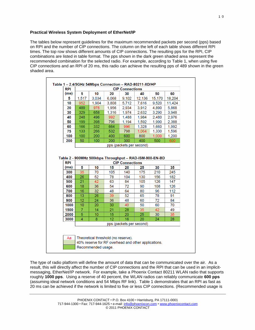
Practical Wireless System Deployment of EtherNet/IP The tables below represent guidelines for the maximum recommended packets per second (pps) based on RPI and the number of CIP connections. The column on the left of each table shows different RPI times. The top row shows different amounts of CIP connections. The resulting pps for the RPI, CIP combinations are listed in table format. The pps shown in the dark green shaded area represent the recommended combination for the selected radio. For example, according to Table 1, when using five CIP connections and an RPI of 20 ms, this radio can achieve the resulting pps of 489 shown in the green shaded area. The type of radio platform will define the amount of data that can be communicated over the air. As a result, this will directly affect the number of CIP connections and the RPI that can be used in an implicit-messaging, EtherNet/IP network. For example, take a Phoenix Contact 80211 WLAN radio that supports roughly 1000 pps. Using a reserve of 40 percent, the WLAN radios can reliably communicate 600 pps (assuming ideal network conditions and 54 Mbps RF link). Table 1 demonstrates that an RPI as fast as 20 ms can be achieved if the network is limited to five or less CIP connections. (Recommended usage is
1 1
PHOENIX CONTACT • P.O. Box 4100 • Harrisburg, PA 17111-0001
717-944-1300 • Fax: 717-944-1625 • e-mail: [email protected] • www.phoenixcontact.com © 2011 PHOENIX CONTACT
shown in dark green) However, if the number of CIP connections is increased to 30, the network RPI would then need to be increased to 100 ms. This is drastically different from a network using Phoenix Contact’s RAD ISM 900MHz Trusted Wireless Ethernet (TWE) radios, which allow roughly 40 pps. With the 40 percent reserve, the network can communicate about 24 pps reliably (assuming ideal network conditions at 500 kbps in throughput mode). With this 24 pps consideration in an implicit messaging EtherNet/IP network, a system limited to five or fewer CIP connections could be realized at an RPI of 400 ms. A network consisting of 30 CIP connections would require an RPI of 3,000 ms. This is significantly slower than a WLAN network and an important consideration when deploying EtherNet/IP over a wireless 900 MHz radio. However, the type of application can help determine which radio platform to deploy. WLAN networks are used in a variety of different types of applications. The WLAN networks generally require line of sight to operate effectively, covering distances up to 1,000-3,000 feet. This type of radio is typically used for mobile operator access, video surveillance, or planned network extensions where high speed network access is required. On the other hand, the 900MHz TWE network can penetrate obstructions and can cover distances up to 15 miles. It is generally used for remote network monitoring and control in SCADA applications. Many SCADA applications do not require high speed, so the slower RPI is acceptable. Or, as an alternative, explicit messaging could be used for EtherNet/IP communications. By using explicit messaging, as opposed to implicit messaging, wireless bandwidth can be better utilized, allowing for more effective communications. This is true regardless of the type of wireless network, but is the most noticeable in 900 MHz TWE networks. By using explicit messaging over a 900 MHz TWE SCADA system, networks of great size (more than 100 nodes), can be realized. This would not be possible using implicit messaging. Summary EtherNet/IP can be utilized over various wireless networks, but bandwidth limitations must be taken into consideration. Having a basic understanding of the amount of data being communicated across the network is a key to a successful wireless EtherNet/IP deployment. In applications where communications are not time-critical, consider using explicit rather than implicit messaging to better manage the available bandwidth across the wireless network. Key system considerations for wireless EtherNet/IP systems:
Be aware of the repercussions unmanaged switches will have on your network. They might be suitable for smaller applications, but use properly places managed switches for sizable applications or to avoid broadcast propagation.
Enable IGMP snooping/multicast filtering on all managed switches and use redundant queriers.
If a device does not support IGMP snooping, you can add it to the device by placing an IGMP-enabled managed switch behind the device.
Calculate packets per second (pps) to determine the required bandwidth.
Reserve 40 percent of your available bandwidth to compensate for poor weather and unexpected RF interference.
Try to limit the use of implicit messaging over 900 MHz FHSS links.
For long distance SCADA applications, explicit messaging over 900 MHz is a best practice.
Short distance, high speed I/O scans will require 2.4/5 GHz WLAN, preferably using 802.11g.
Explicit messaging works best when MSGs are polled sequentially by the .DN or .ER bit.

1 2
PHOENIX CONTACT • P.O. Box 4100 • Harrisburg, PA 17111-0001
717-944-1300 • Fax: 717-944-1625 • e-mail: [email protected] • www.phoenixcontact.com © 2011 PHOENIX CONTACT
About Phoenix Contact Phoenix Contact develops and manufactures industrial electrical and electronic technology products that power, protect, connect and automate systems and equipment for a wide range of industries. Phoenix Contact GmbH & Co. KG, Blomberg, Germany, operates 47 international subsidiaries, including Phoenix Contact USA in Middletown, Pa. Phoenix Contact has more than 10 years’ experience designing industrial wireless radios. To learn more about selecting the best radio for your EtherNet/IP application, visit www.phoenixcontact.com/etherneteasy, or call technical service at 800-322-3225, e-mail [email protected]