Embed Size (px)
Citation preview
Tape Library
User's Guide
C144-E072-01EN

C144-E072-01EN
FOR SAFE OPERATION
This manual contains important information regarding the use and handling of thisproduct. Read this manual thoroughly. Pay special attention to the section "FOR SAFEOPERATION" Use the product according to the instructions and information available inthis manual. Keep this manual handy for further reference.
Fujitsu makes every effort to prevent users and bystanders from being injured or damageto their property. Use the product according to this manual.
ABOUT THIS PRODUCT
This product is designed and manufactured for use in standard applications such as officework, personal devices and household appliances. This product is not intended forspecial uses (atomic controls, aeronautic or space systems, mass transport controls,medical devices for life support, or weapons firing controls) where particularly highreliability requirements exist, where the pertinent levels of safety are not guaranteed, orwhere a failure or operational error could threaten a life or cause a physical injury(hereafter referred to as "mission-critical" use). Customers considering the use of theseproducts for mission-critical applications must have safety-assurance measures in placebeforehand. Moreover, they are requested to consult our sales representative beforeembarking on such specialized use.
TRADEMARKS ACKNOWLEDGEMENTS
- LTO, Liner Tape Open and Ultrium are registered trademarks of Hewlett-PackardCompany, IBM Corporation and Seagate Technology.
- Microsoft, Windows, MS, and MS-DOS are registered trademarks of MicrosoftCorporation in the United States or certain other countries.
- Solaris is a trademark of Sun Microsystems, Inc.
- Java and all other trademarks and logos related Java are registered trademarks of SunMicrosystems, Inc in the United States or certain other countries.
- Netscape is a trademark of Netscape Communications Corporation.
- VERITAS is a registered trademark of VERITAS Software Corporation in theUnited States or certain other countries.
- Logos of VERITAS and VERITAS NetBackup are registered trademarks ofVERITAS Software Corporation in the United States or certain other countries.
- ARCserve and BrightStor are trademarks of Computer Associates International in theUnited States or certain other countries.
- All other corporation names and product names mentioned herein are the trademarksor registered trademarks of their respective owners.
RADIO FREQUENCY INTERFERENCE STATEMENT
The following notice is for EU users only.
WARNING: This is a product which meets Class A of EN55022. In a domesticenvironment this product may cause radio interference in which case the user may berequired to take adequate measures.
C144-E072-01EN
The following notice is for USA users only.
This equipment has been tested and found to comply with the limits for a Class A digitaldevice, pursuant to Part 15 of the FCC Rules. These limits are designed to providereasonable protection against harmful interference when the equipment is operated in acommercial environment. This equipment generates, uses, and can radiate radiofrequency energy and, if not installed and used in accordance with the instruction manual,may cause harmful interference to radio communications. Operation of this equipment ina residential area is likely to cause harmful interference in which case the user will berequired to correct the interference at his own expense.
Laser Standard
The Fibre Channel printed circuit board contains a laser system (GBIC or GLM module).Laser systems are classified as Class I Laser Equipment by the radiation standards of theDepartment of Health and Human Services (DHHS) in accordance with RadiationControl for Health and Safety Act of 1968 and also based on the safety requirements forlaser products in EN60825-1 (+A11). The certificate of conformance is affixed to themodule.
RELATED STANDARDS
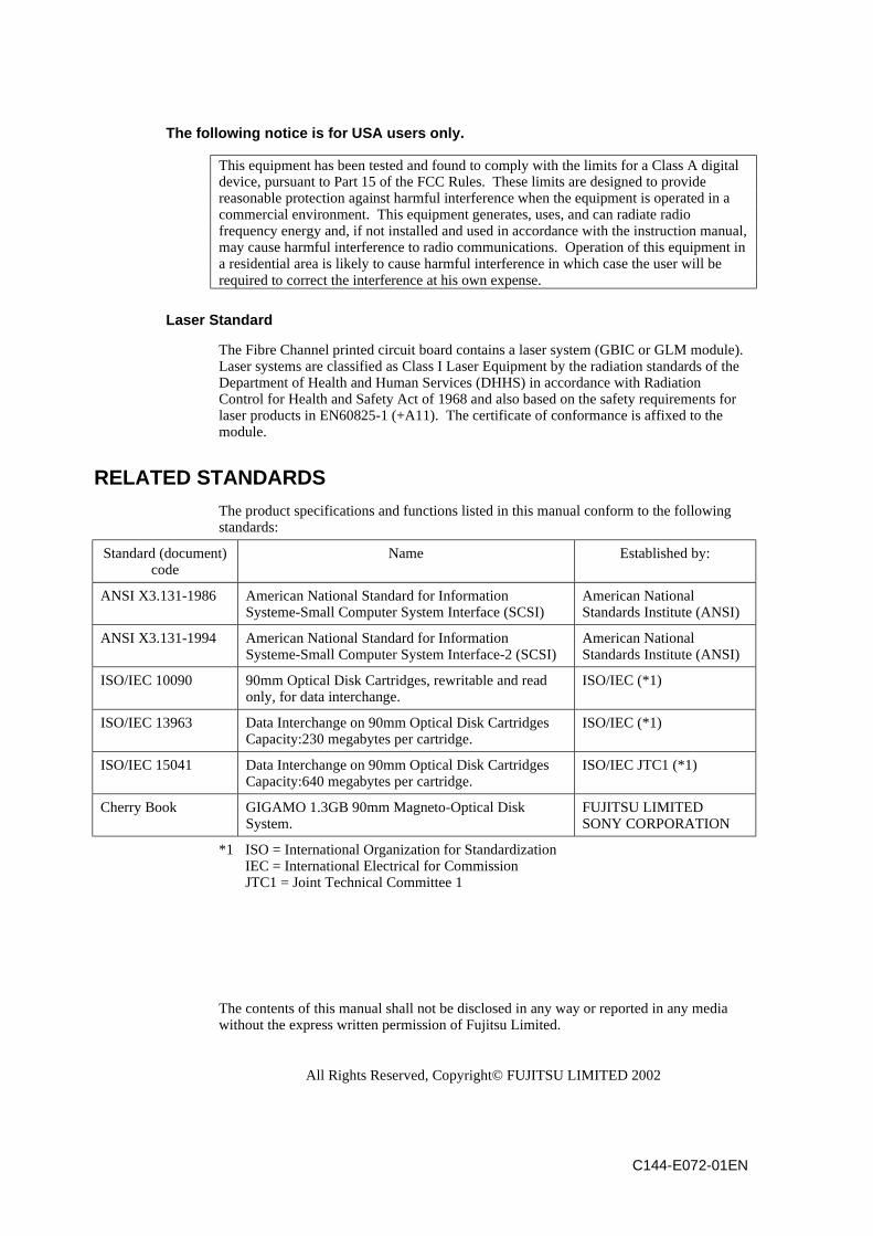
The product specifications and functions listed in this manual conform to the followingstandards:
Standard (document)code
Name Established by:
ANSI X3.131-1986 American National Standard for InformationSysteme-Small Computer System Interface (SCSI)
American NationalStandards Institute (ANSI)
ANSI X3.131-1994 American National Standard for InformationSysteme-Small Computer System Interface-2 (SCSI)
American NationalStandards Institute (ANSI)
ISO/IEC 10090 90mm Optical Disk Cartridges, rewritable and readonly, for data interchange.
ISO/IEC (*1)
ISO/IEC 13963 Data Interchange on 90mm Optical Disk CartridgesCapacity:230 megabytes per cartridge.
ISO/IEC (*1)
ISO/IEC 15041 Data Interchange on 90mm Optical Disk CartridgesCapacity:640 megabytes per cartridge.
ISO/IEC JTC1 (*1)
Cherry Book GIGAMO 1.3GB 90mm Magneto-Optical DiskSystem.
FUJITSU LIMITEDSONY CORPORATION
*1 ISO = International Organization for StandardizationIEC = International Electrical for CommissionJTC1 = Joint Technical Committee 1
The contents of this manual shall not be disclosed in any way or reported in any mediawithout the express written permission of Fujitsu Limited.
All Rights Reserved, Copyright© FUJITSU LIMITED 2002
C144-E072-01EN
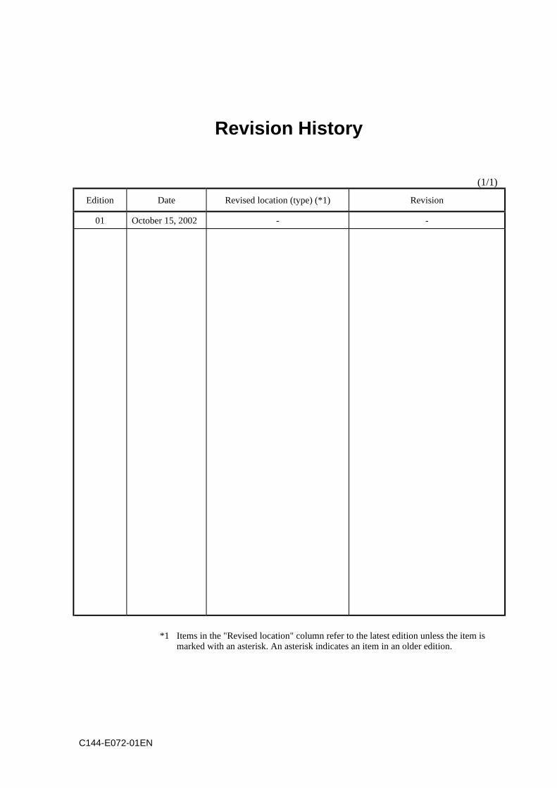
Revision History
(1/1)
Edition Date Revised location (type) (*1) Revision
01 October 15, 2002 - -
*1 Items in the "Revised location" column refer to the latest edition unless the item ismarked with an asterisk. An asterisk indicates an item in an older edition.

C144-E072-01EN i
Preface
This manual describes the LT160 magnetic tape library.
This manual first provides an overview of the tape library and then detailed informationabout the tape library. The detailed information includes specifications, installationrequirements and procedures for incorporating the tape library into a system, andinformation about how to clean the tape library.
The manual is intended for users who have a basic knowledge of magnetic tape librariesand how they are used in computer systems.
The organization of manuals related to the LT160 tape library and the scope of thismanual are indicated in the Manual Set section later. Refer to related manuals asnecessary.
The organization and contents of this manual are explained below. This information isfollowed by important information related to handling of the LT160.
Organization of this manual
This manual has seven chapters, appendixes, a glossary, and a list of acronyms andabbreviations.
Chapter 1 Overview
This chapter explains the components and functions of the library.
Chapter 2 Introducing and Preparing the Library
This chapter explains how to install, connect, and set up the library, install the host, turnpower on and off, and insert and eject cartridges.
Chapter 3 Library Operation
This chapter explains how to insert or eject a cartridge and how to clean a drive.
Chapter 4 Operator Panel Operation
This chapter explains the screen configuration of the operator panel, the menu hierarchy,referencing of library/drive information, setup of library/drive information, and libraryprocedures, such as opening of the magazine door.
Chapter 5 Remote Panel Operation
This chapter explains the remote panel login method, menu hierarchy, referencing of thelibrary/drive information, and setup of library/drive information.
Chapter 6 Troubleshooting
This chapter provides an overview of maintenance work, explains types of errors andtheir solutions, and provides troubleshooting information for ordinary problems.
Preface
ii C144-E072-01EN
Chapter 7 Cartridge Media and Bar Code Label Specifications
This chapter provides information on Ultrium cartridges and cleaning cartridges, handlingof cartridges, bar code label specifications, and maintenance and the service life ofcartridges.
Appendix A Model Configurations
This appendix provides a the diagram of the configuration of each library.
Appendix B Technical Specifications
This appendix provides ambient environment, library, physical, and Fibre Channel cablespecifications.
Conventions
In this manual, a button or menu that is referred to is indicated as, for example, [OK].
Preface
C144-E072-01EN iii
Conventions for Alert Messages
This manual uses the following conventions to show the alert messages. An alertmessage consists of an alert signal and alert statements. The alert signal consists of analert symbol and a signal word or just a signal word.
The following are the alert signals and their meanings:
CAUTION This indicates a hazardous situation could result in minor ormoderate personal injury if the user does not perform theprocedure correctly. This alert signal also indicates thatdamages to the product or other property may occur if the userdoes not perform the procedure correctly.
IMPORTANT This indicates information that could help the user use theproduct more efficiently.
In the text, the alert signal is centered, followed below by the indented message.
A wider line space precedes and follows the alert message to show where the alertmessage begins and ends. The following is an example:
(Example)
CAUTIONInjury: Never move your hands away from the drive module until itis placed in a safe place. Otherwise, the drive module may drop,causing injury if you move your hands away from it after pulling itout beyond this stopper.
The main alert messages in the text are also listed in the "Important Alert Items."
Notice
- If any information in this manual is unclear or incorrect, please complete thecomment form at the back of this manual and give it to a Fujitsu systems engineer orsalesperson.
- The contents of this manual may be revised without prior notice.

C144-E072-01EN v
Important Alert Items
Important Alert Messages
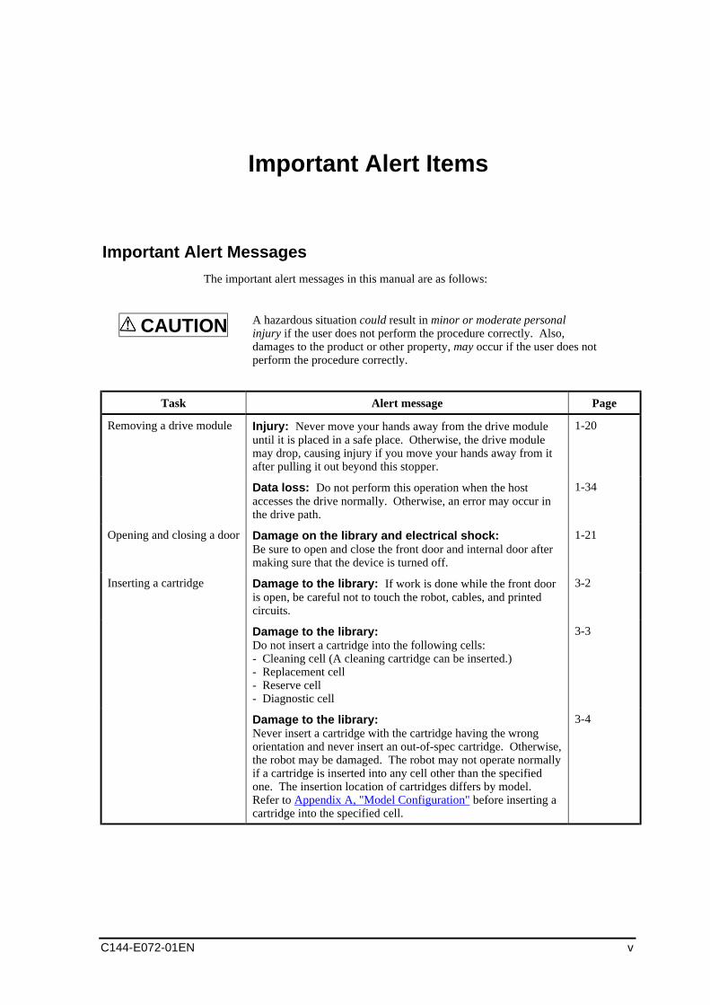
The important alert messages in this manual are as follows:
CAUTION A hazardous situation could result in minor or moderate personalinjury if the user does not perform the procedure correctly. Also,damages to the product or other property, may occur if the user does notperform the procedure correctly.
Task Alert message Page
Removing a drive module Injury: Never move your hands away from the drive moduleuntil it is placed in a safe place. Otherwise, the drive modulemay drop, causing injury if you move your hands away from itafter pulling it out beyond this stopper.
1-20
Data loss: Do not perform this operation when the hostaccesses the drive normally. Otherwise, an error may occur inthe drive path.
1-34
Opening and closing a door Damage on the library and electrical shock:Be sure to open and close the front door and internal door aftermaking sure that the device is turned off.
1-21
Inserting a cartridge Damage to the library: If work is done while the front dooris open, be careful not to touch the robot, cables, and printedcircuits.
3-2
Damage to the library:Do not insert a cartridge into the following cells:- Cleaning cell (A cleaning cartridge can be inserted.)- Replacement cell- Reserve cell- Diagnostic cell
3-3
Damage to the library:Never insert a cartridge with the cartridge having the wrongorientation and never insert an out-of-spec cartridge. Otherwise,the robot may be damaged. The robot may not operate normallyif a cartridge is inserted into any cell other than the specifiedone. The insertion location of cartridges differs by model.Refer to Appendix A, "Model Configuration" before inserting acartridge into the specified cell.
3-4
Important Alert Items
vi C144-E072-01EN
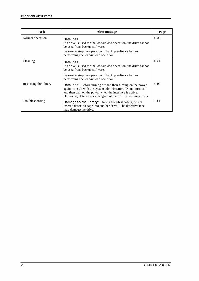
Task Alert message Page
Normal operation Data loss:If a drive is used for the load/unload operation, the drive cannotbe used from backup software.
Be sure to stop the operation of backup software beforeperforming the load/unload operation.
4-40
Cleaning Data loss:If a drive is used for the load/unload operation, the drive cannotbe used from backup software.
Be sure to stop the operation of backup software beforeperforming the load/unload operation.
4-41
Restarting the library Data loss: Before turning off and then turning on the poweragain, consult with the system administrator. Do not turn offand then turn on the power when the interface is active.Otherwise, data loss or a hang-up of the host system may occur.
6-10
Troubleshooting Damage to the library: During troubleshooting, do notinsert a defective tape into another drive. The defective tapemay damage the drive.
6-11
C144-E072-01EN vii
Important Information on Handling
Maintenance
WARNINGUsers must not attempt to repair the LT160 by themselves. Ask Fujitsu to dispatch one ofits engineers or an engineer authorized by Fujitsu for maintenance work.
Disposal of the LT160 and Packing Materials
If you need to dispose of the LT160, follow the instructions provided by maintenancepersonnel.
Expendable Supplies
Use Fujitsu-designated expendable supplies for the LT160. Using other materials mayresult in injury to users and bystanders or damage to their property.
Modification or Reconditioning of the LT160
Do not modify the LT160 or overhaul a used product. Doing so may result in injury tousers and bystanders or damage to their property.
Operating Environment
This product is designed for use in Japan and cannot be used outside Japan. Fujitsuassumes no responsibility for any consequences resulting from use of the LT160 outsideJapan.
Collecting and recycling products used in offices
The LT160 tape library, which is the property of a corporation, must be handled asindustrial waste when it disposed of after use. A manifest form (waste managementform) must be issued when it is to be disposed of. If you request that Fujitsu dispose ofthe tape library, Fujitsu's affiliate logistics company (company permitted to collect andtransport industrial waste) will pick the tape library up.
Address any inquiries or applications to Fujitsu Recycle System or to the Eco Center ofFujitsu Logistics.
- Fujitsu Recycle System
(http:/eco.fujitsu.com/info/eco19990827.html)
Important Information on Handling
viii C144-E072-01EN
- Eco Center of Fujitsu Logistics
(Telephone: 045-470-5305)
Fujitsu Recycle System, which has constructed Fujitsu's recycling system, disassemblesused products at its recycle center and segregates components for reuse or recycles themas materials.
Disposal of magnetic tape
Handle magnetic tape that is disposed of as described in "Request for collecting andrecycling products used in offices".
LCD unit (operator panel)
The LCD unit (operator panel) in the LT160 contains mercury. To ensure safety, observethe precautions:
- Do not swallow mercury. Mercury is toxic to the body if swallowed.
- Do not handle the LCD unit in such a way that it becomes gaseous, a powder, or aliquid. Inhaling or swallowing mercury that has been burned, crushed, or liquefiedwith chemical treatment is hazardous.
- Dispose of the LCD unit in accordance with Japanese laws and the waste disposalregulations of your company.
- Dispose of the LCD unit by segregating it from municipal waste or domestic waste.
Bar code reader light source
Do not directly stare at the light source of the bar code reader installed in the LT160.Looking directly at the laser or flash emitted from the light source can cause eye damage.
Manual Organization
C144-E072-01EN ix
Manual Organization
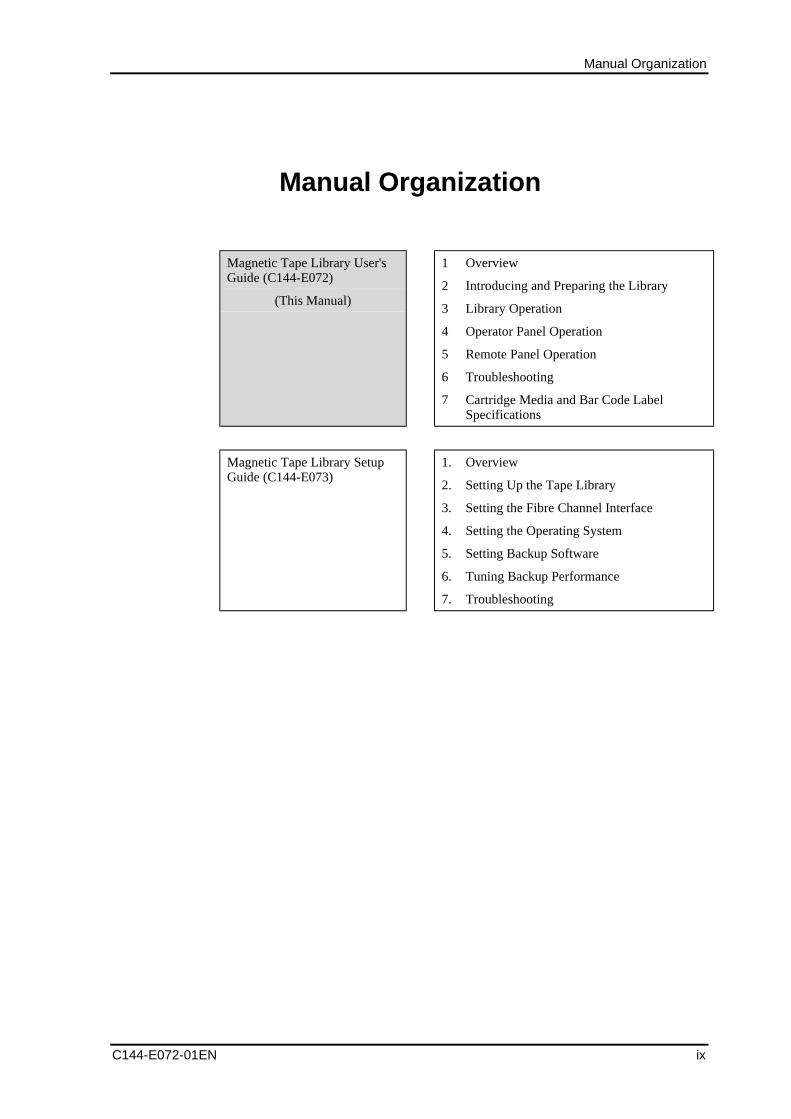
Magnetic Tape Library User'sGuide (C144-E072)
(This Manual)
1 Overview
2 Introducing and Preparing the Library
3 Library Operation
4 Operator Panel Operation
5 Remote Panel Operation
6 Troubleshooting
7 Cartridge Media and Bar Code LabelSpecifications
Magnetic Tape Library SetupGuide (C144-E073)
1. Overview
2. Setting Up the Tape Library
3. Setting the Fibre Channel Interface
4. Setting the Operating System
5. Setting Backup Software
6. Tuning Backup Performance
7. Troubleshooting

C144-E072-01EN xi
Contents
Preface.....................................................................................................................i
Important Alert Items ..............................................................................................v
Important Information on Handling ....................................................................... vii
Manual Organization.............................................................................................. ix
Contents.................................................................................................................xi
Chapter 1 Overview ............................................................................................ 1-1
1.1 Device Configuration ...................................................................................... 1-11.1.1 Device outline..................................................................................... 1-11.1.2 Robot .................................................................................................. 1-41.1.3 Each component of the library............................................................ 1-7
1.1.3.1 Configuration of the basic model components ..................... 1-71.1.3.2 Special cells.......................................................................... 1-81.1.3.3 Configuration and upgrade pattern for each model .............. 1-9
1.1.4 Cartridge Access Station (CAS) ....................................................... 1-101.1.4.1 Inserting a magazine from CAS ......................................... 1-111.1.4.2 Ejecting a magazine from CAS .......................................... 1-15
1.1.5 Magazine .......................................................................................... 1-161.1.5.1 Inserting cartridges into the magazine................................ 1-171.1.5.2 Ejecting cartridges from the magazine ............................... 1-18
1.1.6 Drive module .................................................................................... 1-191.1.7 Opening/Closing the door................................................................. 1-21
1.1.7.1 Opening and closing the front door .................................... 1-211.1.7.2 Opening and closing the internal door................................ 1-231.1.7.3 Opening and closing the rear door...................................... 1-25
1.1.8 Hardware module (interface card, power supply, and BCR) ............ 1-271.2 Functional Overview ..................................................................................... 1-29
1.2.1 FC control function........................................................................... 1-291.2.2 Fast load function ............................................................................. 1-291.2.3 Inventory function ............................................................................ 1-301.2.4 Manual load function........................................................................ 1-311.2.5 Cleaning function ............................................................................. 1-31
1.2.5.1 Auto-cleaning function....................................................... 1-311.2.5.2 Manual cleaning function................................................... 1-32
1.2.6 Functions for recovery...................................................................... 1-331.2.6.1 Recovery method when a drive error occurs ...................... 1-331.2.6.2 Recovery method when a library error occurs.................... 1-331.2.6.3 Operation to be performed when the host goes down
and a cartridge remaining in the drive should beunloaded ............................................................................. 1-33
1.2.6.4 Auto-eject function............................................................. 1-341.2.7 Remote panel function...................................................................... 1-34
Contents
xii C144-E072-01EN
1.2.8 E-mail function................................................................................. 1-351.2.9 SNMP function................................................................................. 1-36
Chapter 2 Introducing and Preparing the Library ............................................... 2-1
2.1 Installing the Library....................................................................................... 2-12.1.1 Conditions for library installation ...................................................... 2-1
2.2 Preparing the Host Installation........................................................................ 2-42.3 Connecting the Library ................................................................................... 2-52.4 Power-on and Power-off ................................................................................. 2-7
2.4.1 Power-on method ............................................................................... 2-72.4.1.1 If RCI is not used ................................................................. 2-72.4.1.2 If RCI is used ....................................................................... 2-7
2.4.2 Power-off method............................................................................... 2-82.4.2.1 If RCI is not used ................................................................. 2-82.4.2.2 If RCI is used ....................................................................... 2-8
2.5 Checking the Library and Drive Settings........................................................ 2-92.5.1 Checking the drive settings ................................................................ 2-92.5.2 Checking the library settings.............................................................. 2-9
2.5.2.1 Checking the target ID setting ............................................. 2-92.5.2.2 Checking the host WWPN setting........................................ 2-92.5.2.3 Checking the auto-cleaning function setting........................ 2-92.5.2.4 Checking the auto-inventory function setting ...................... 2-92.5.2.5 Checking the auto-eject function setting.............................. 2-92.5.2.6 Checking the fast load function setting.............................. 2-102.5.2.7 Checking the time and date setting .................................... 2-102.5.2.8 Checking the remote panel settings ................................... 2-10
2.6 Checking the Host Settings ........................................................................... 2-11
Chapter 3 Library Operation ............................................................................... 3-1
3.1 Inserting and Ejecting a Cartridge (Data Cartridge) ....................................... 3-13.1.1 Inserting/Ejecting a cartridge by opening the front door.................... 3-23.1.2 Inserting/Ejecting cartridges from CAS ............................................. 3-8
3.1.2.1 Inserting cartridges from CAS ............................................. 3-83.1.2.2 Ejecting into CAS ................................................................ 3-8
3.2 Cleaning the Drive .......................................................................................... 3-93.3 Power to the unit ........................................................................................... 3-103.4 Turning on the server .................................................................................... 3-11
Chapter 4 Operator Panel Operation.................................................................. 4-1
4.1 Overview of the Operator Panel...................................................................... 4-14.1.1 Touch-panel operation ....................................................................... 4-14.1.2 Window type ...................................................................................... 4-3
4.1.2.1 Initialization window ........................................................... 4-34.1.2.2 Home window...................................................................... 4-34.1.2.3 Menu window ...................................................................... 4-4
4.1.3 Window configuration ....................................................................... 4-64.2 Referencing the Status of the Library/Drive ................................................... 4-94.3 Referencing Library Information .................................................................. 4-11
4.3.1 Referencing cell cartridge information............................................. 4-114.3.1.1 Referencing general cell cartridge information.................. 4-114.3.1.2 Referencing magazine cell cartridge information .............. 4-124.3.1.3 Referencing cleaning cell cartridge information................ 4-134.3.1.4 Referencing reserve cell cartridge information.................. 4-144.3.1.5 Referencing diagnostics cell cartridge information ........... 4-16
4.3.2 Referencing information about the host interface ............................ 4-174.3.2.1 Referencing the Target ID and LUN of each adapter ........ 4-174.3.2.2 Referencing the host WWPN permitted for each
adapter................................................................................ 4-19
Contents
C144-E072-01EN xiii
4.3.3 Referencing setup information for the library .................................. 4-204.3.4 Referencing information about the drive .......................................... 4-204.3.5 Referencing setup information for the network ................................ 4-224.3.6 Referencing error information .......................................................... 4-22
4.3.6.1 Referencing hardware error information for the library ..... 4-224.3.6.2 Referencing hardware error information for the drive ....... 4-234.3.6.3 Referencing alarm error information.................................. 4-24
4.3.7 Referencing the version number of the library/drive ........................ 4-244.4 Setting the Target ID of the Drive................................................................. 4-254.5 Setting Library Information........................................................................... 4-28
4.5.1 Setting information about the host interface..................................... 4-284.5.1.1 Setting the library Target (Loop) ID for each adapter ........ 4-284.5.1.2 Setting the host WWPN permitted for each adapter
(If needed) .......................................................................... 4-314.5.1.3 Registering a host WWPN list............................................ 4-334.5.1.4 Deleting from the WWPN list ............................................ 4-33
4.5.2 Setting library information ............................................................... 4-344.5.3 Setting information about the network ............................................. 4-354.5.4 Setting the clock ............................................................................... 4-364.5.5 Setting the screen saver .................................................................... 4-38
4.6 Opening the Magazine Door ......................................................................... 4-394.7 Loading/Unloading a Cartridge..................................................................... 4-41
4.7.1 Loading a cartridge contained in the magazine into the drive .......... 4-414.7.2 Unloading a cartridge loaded from the magazine ............................. 4-42
4.8 Cleaning the Drive Manually ........................................................................ 4-434.9 Inserting/Ejecting a Cleaning Cartridge ........................................................ 4-45
4.9.1 Inserting a cleaning cartridge............................................................ 4-454.9.2 Ejecting a cleaning cartridge ............................................................ 4-46
4.10R .................................................................................................................... 4-484.11Releasing the Front Door Open Status .......................................................... 4-504.12Unloading a Cartridge Loaded from the Host ............................................... 4-514.13Making an Inventory ..................................................................................... 4-52
Chapter 5 Remote Panel Operation ................................................................... 5-1
5.1 Overview ......................................................................................................... 5-15.1.1 Login method...................................................................................... 5-35.1.2 Frame configuration ........................................................................... 5-65.1.3 Menu tree............................................................................................ 5-7
5.2 Referencing the Status of Drive/Library ......................................................... 5-85.3 Referencing Library Information .................................................................. 5-12
5.3.1 Referencing information about the cartridge in the cell ................... 5-125.3.1.1 Referencing the general cell ............................................... 5-135.3.1.2 Referencing the magazine cell............................................ 5-165.3.1.3 Referencing the drive cell................................................... 5-175.3.1.4 Searching using the bar code label ..................................... 5-18
5.3.2 Referencing setup information for the host interface........................ 5-195.3.3 Referencing setup information for the library .................................. 5-225.3.4 Referencing setup information for the drive..................................... 5-235.3.5 Referencing setup information for the network ................................ 5-245.3.6 Referencing error history information .............................................. 5-255.3.7 Referencing the firmware version number ....................................... 5-275.3.8 Referencing setup information for e-mail......................................... 5-285.3.9 Referencing setup information for SNMP ........................................ 5-30
5.4 Setting Target ID of the Drive....................................................................... 5-315.5 Setting Library Information........................................................................... 5-32
5.5.1 Setting information about the host interface..................................... 5-325.5.2 Setting library information ............................................................... 5-345.5.3 Setting information about the network ............................................. 5-355.5.4 Setting the clock ............................................................................... 5-36
Contents
xiv C144-E072-01EN
5.5.5 Setting the e-mail function ............................................................... 5-385.5.6 Setting the SNMP agent ................................................................... 5-405.5.7 Changing the password .................................................................... 5-42
5.6 Operating the Library.................................................................................... 5-435.6.1 Cleaning the drive manually ............................................................ 5-435.6.2 Operating the trace file..................................................................... 5-455.6.3 Saving setup information for the library/drive ................................. 5-465.6.4 Restoring setup information for the library/drive............................. 5-495.6.5 Executing an SNMP trap test ........................................................... 5-50
Chapter 6 Troubleshooting ................................................................................. 6-1
6.1 Drive/Library Maintenance............................................................................. 6-16.1.1 Procedure for the drive maintenance.................................................. 6-16.1.2 Procedure for the library maintenance ............................................... 6-1
6.2 Removing Cartridges when an Error Occurs .................................................. 6-26.2.1 Removing cartridges from the hand mechanism when the robot
fails..................................................................................................... 6-26.2.2 Removing cartridges from CAS when the CAS external door
cannot be opened................................................................................ 6-66.3 Error Status ..................................................................................................... 6-7
6.3.1 Error type of the drive ........................................................................ 6-76.3.2 Error type of the library...................................................................... 6-8
6.3.2.1 Hardware error of the library ............................................... 6-86.3.2.2 Library alarm error............................................................... 6-9
6.4 General Troubleshooting .............................................................................. 6-106.4.1 Power ............................................................................................... 6-106.4.2 Connections...................................................................................... 6-106.4.3 Cartridge........................................................................................... 6-116.4.4 CAS.................................................................................................. 6-116.4.5 Compatibility.................................................................................... 6-116.4.6 Library performance......................................................................... 6-126.4.7 Cleaning ........................................................................................... 6-126.4.8 Operator panel.................................................................................. 6-126.4.9 Remote panel.................................................................................... 6-13
Chapter 7 Cartridge Media and Bar Code Label Specifications......................... 7-1
7.1 Ultrium Cartridge Information........................................................................ 7-17.2 Replacement Period ........................................................................................ 7-27.3 Handling the Tape cartridge............................................................................ 7-3
7.3.1 Notes on storage................................................................................. 7-37.3.2 Notes on transportation ...................................................................... 7-37.3.3 Notes on handling .............................................................................. 7-47.3.4 Notes on the reader pin ...................................................................... 7-47.3.5 Notes on label affixing ....................................................................... 7-4
7.4 Bar Code Label Specification and Handling................................................... 7-57.4.1 Specifying the label string.................................................................. 7-5
7.4.1.1 Specify the volume area....................................................... 7-67.4.1.2 Deleting the media area ....................................................... 7-67.4.1.3 Specifying the label for cleaning cartridge .......................... 7-6
7.4.2 Notes on label affixing ....................................................................... 7-67.5 Precautions to Follow when Using the Cartridge............................................ 7-7
Appendix A Model Configuration ........................................................................A-1
A.1 Model Configuration of Basic Model A20(10 drive options/98 cell options/10 CASs)...................................................A-2
A.2 Model Configuration of Basic Model A20(10 drive options/182 cell options/10 CASs).................................................A-3
Contents
C144-E072-01EN xv
A.3 Model Configuration of Basic Model A20 (10 drive options/221 celloptions/10 CASs) .......................................................................................... A-4
A.4 Model Configuration of Basic Model A32 (16 drive options/89 celloptions/10 CASs) .......................................................................................... A-5
A.5 Model Configuration of Basic Model A32 (16 drive options/167 celloptions/10 CASs) .......................................................................................... A-6
Appendix B Technical Specifications..................................................................B-1
B.1 Library/Drive Specifications .......................................................................... B-1B.1.1 Model A20 specification (drive: 1 to 10 units installed) ................... B-1B.1.2 Model A32 specification (drive: 1 to 16 units installed) ................... B-2B.1.3 Installed tape drive specification ....................................................... B-4
B.2 Environment Specifications ........................................................................... B-5
Glossary........................................................................................................... GL-1
Index ..................................................................................................................IN-1

Contents
C144-E072-01EN xvii
Illustrations
FigureFigure 1.1 Appearance (front)........................................................................... 1-1Figure 1.2 Appearance (rear) ............................................................................ 1-2Figure 1.3 Appearance (rear: with the open rear door) ..................................... 1-3Figure 1.4 Appearance (isometric view from left: with left side board
removed) .......................................................................................... 1-3Figure 1.5 Hand mechanism ............................................................................. 1-4Figure 1.6 Robot appearance............................................................................. 1-6Figure 1.7 Configuration diagram of the standard model components ............. 1-7Figure 1.8 CAS mechanism appearance ......................................................... 1-10Figure 1.9 Magazine insertion method 1......................................................... 1-12Figure 1.10 Magazine insertion method 2......................................................... 1-13Figure 1.11 Magazine insertion method 3 (magazine regular position)............ 1-14Figure 1.12 Magazine ejection method ............................................................. 1-15Figure 1.13 Figure for explaining the magazine mechanism ............................ 1-16Figure 1.14 Figure for explaining cartridge insertion method a........................ 1-17Figure 1.15 Figure for explaining cartridge insertion method b........................ 1-18Figure 1.16 Drive module appearance .............................................................. 1-19Figure 1.17 Front door ...................................................................................... 1-21Figure 1.18 Internal door .................................................................................. 1-23Figure 1.19 Internal door (when open).............................................................. 1-24Figure 1.20 Rear door ....................................................................................... 1-25Figure 1.21 Rear door (when open) .................................................................. 1-26Figure 1.22 LED sections (device rear view) (1/2) .......................................... 1-27Figure 1.22 LED sections (device rear view) (2/2) .......................................... 1-28Figure 1.23 Cable insertion port (Lower part on the rear side of the device).... 1-28Figure 1.24 SNMP function .............................................................................. 1-36
Figure 2.1 Space required for library installation.............................................. 2-2Figure 2.2 Removing transport metal brackets ................................................. 2-3Figure 2.3 Fiber channel wiring methods.......................................................... 2-5Figure 2.4 Power switch (power-on)................................................................. 2-7Figure 2.5 Power switch (power-off) ................................................................ 2-8
Figure 3.1 Cartridge insertion direction ............................................................ 3-3Figure 3.2 Picker mechanism protruding from the hand mechanism................ 3-5Figure 3.3 Picker mechanism that has been completely inserted
into the hand mechanism ................................................................. 3-5Figure 3.4 Hand mechanism placed on the right edge ...................................... 3-6Figure 3.5 Hand mechanism placed on the left edge......................................... 3-6Figure 3.6 Parts requiring grease in the robot ................................................... 3-7
Figure 4.1 Initialization window ....................................................................... 4-3Figure 4.2 Home window.................................................................................. 4-4Figure 4.3 Menu window .................................................................................. 4-4Figure 4.4 Configuration of home window and menu window......................... 4-6Figure 4.5 Selecting the [Cell Map] button..................................................... 4-11Figure 4.6 Cartridge information reference window for general cells ............ 4-12
Contents
xviii C144-E072-01EN
Figure 4.7 Reference window for magazine cell cartridge information ..........4-13Figure 4.8 Reference window for cleaning cell cartridge information ............4-14Figure 4.9 Reference window for reserve cell cartridge information ..............4-15Figure 4.10 Cartridge information reference window for diagnostic cell..........4-16Figure 4.11 Selecting the [Host I/F] button .......................................................4-17Figure 4.12 Host interface information reference window
(When the Fabric connection is set) ...............................................4-18Figure 4.13 Host interface information reference window
(When the AL connection/Hard address are set)............................4-18Figure 4.14 Host interface information reference window
(When the AL connection/Soft address are set) .............................4-19Figure 4.15 Drive information reference window
(When the Soft address is set) ........................................................4-21Figure 4.16 Drive information reference window
(When the Hard address is set) .......................................................4-21Figure 4.17 Hardware error information display window of the library............4-23Figure 4.18 Hardware error information display window of the drive ..............4-23Figure 4.19 Selecting the [Drive] button ...........................................................4-25Figure 4.20 Target (LOOP) ID setup window of the drive................................4-26Figure 4.21 Selecting the [Host I/F] button. ......................................................4-28Figure 4.22 Selecting the [Target ID] button.....................................................4-29Figure 4.23 LOOP ID setup window of the host ...............................................4-30Figure 4.24 Selecting the [Host WWPN] button ...............................................4-31Figure 4.25 Host WWPN setting window .........................................................4-32Figure 4.26 Host WWPN list registration window............................................4-33Figure 4.27 Selecting the [CAS] button.............................................................4-39Figure 4.28 Selecting the [CAS Open] button ...................................................4-39Figure 4.29 Home window displaying a library hardware error........................4-48Figure 4.30 Home window displaying a drive hardware error ..........................4-49Figure 4.31 Selecting the [Reset] button ...........................................................4-49Figure 4.32 Selecting the [Manual Eject] button ...............................................4-51Figure 4.33 Selecting the [Inventory] button.....................................................4-52
Figure 5.1 Remote panel starting window.........................................................5-2Figure 5.2 Login window ..................................................................................5-3Figure 5.3 Window displayed when the login fails ...........................................5-4Figure 5.4 Window displayed for duplicate login .............................................5-5Figure 5.5 Frame configuration of the remote panel .........................................5-6Figure 5.6 Status reference window of the drive/library ...................................5-8Figure 5.7 Normal window display (no errors) (upper frame) ..........................5-9Figure 5.8 Window display when there is an error (upper frame) .....................5-9Figure 5.9 Cell map window ...........................................................................5-12Figure 5.10 General cell cartridge information display window .......................5-13Figure 5.11 Magazine cell cartridge information display window ....................5-16Figure 5.12 Drive cell cartridge information display window...........................5-18Figure 5.13 Bar code label search window........................................................5-19Figure 5.14 Host interface setup information display window..........................5-20Figure 5.15 Library setup information display window ....................................5-22Figure 5.16 Drive setup information display window .......................................5-23Figure 5.17 Network setup information display window ..................................5-24Figure 5.18 Error history display window.........................................................5-25Figure 5.19 Firmware version number display window ....................................5-27Figure 5.20 E-mail setup information display window .....................................5-28Figure 5.21 SNMP setup information display window .....................................5-30Figure 5.22 Drive setup window .......................................................................5-31Figure 5.23 Adapter selection window..............................................................5-32Figure 5.24 Host interface setting window........................................................5-33Figure 5.25 Library information setting window...............................................5-34Figure 5.26 Network information setting window.............................................5-35Figure 5.27 Date/time setting window...............................................................5-37
Contents
C144-E072-01EN xix
Figure 5.28 E-mail function setting window..................................................... 5-38Figure 5.29 SNMP agent setting window ......................................................... 5-40Figure 5.30 Password change window.............................................................. 5-42Figure 5.31 Manual cleaning operation window............................................... 5-44Figure 5.32 Trace file operation window .......................................................... 5-45Figure 5.33 Library/drive setup information save window............................... 5-46Figure 5.34 Confirming that library/drive setup information has been
downloaded.................................................................................... 5-47Figure 5.35 Completion of saving setup information for the library/drive ....... 5-48Figure 5.36 Specifying a file from which setup information for the
library/drive should be restored ..................................................... 5-49Figure 5.37 SNMP trap test start window ......................................................... 5-50Figure 5.38 SNMP trap transmission completion window ............................... 5-51
Figure 6.1 Hand mechanism ............................................................................. 6-2Figure 6.2 Procedure 1 for removing cartridges................................................ 6-3Figure 6.3 Procedure 2 for removing cartridges................................................ 6-3Figure 6.4 Procedure 3 for removing cartridges................................................ 6-4Figure 6.5 Procedure 4 for removing cartridges................................................ 6-5Figure 6.6 Unlocking the external door of CAS................................................ 6-6Figure 6.7 Operator panel window when a hardware error occurred
in the drive ....................................................................................... 6-7Figure 6.8 Operator panel window when a hardware error
of the library occurs ......................................................................... 6-8Figure 6.9 Operator panel window when a library alarm error occurs.............. 6-9
Figure 7.1 LTO Ultrium 1 tape cartridge .......................................................... 7-2Figure 7.2 Bar code label string ........................................................................ 7-5Figure 7.3 Bar code label affixing location....................................................... 7-6
Figure A.1 Model Configuration of Basic Model A20(10 drive options/98 cell options/10 CASs) .................................... A-2
Figure A.2 Model Configuration of Basic Model A20(10 drive options/182 cell options/10 CASs) .................................. A-3
Figure A.3 Model Configuration of Basic Model A20(10 drive options/221 cell options/10 CASs) .................................. A-4
Figure A.4 Model Configuration of Basic Model A32(16 drive options/89 cell options/10 CASs) .................................... A-5
Figure A.5 Model Configuration of Basic Model A32(16 drive options/167 cell options/10 CASs) .................................. A-6
Contents
xx C144-E072-01EN
TableTable 1.1 Configuration list of model elements ...............................................1-9Table 1.2 Upgrade pattern (A20) .....................................................................1-9Table 1.3 Upgrade pattern (A32) .....................................................................1-9
Table 4.1 Library status....................................................................................4-9Table 4.2 Drive/Cartridge.................................................................................4-9Table 4.3 Drive/cartridge status (added to the end of indications of library
or drive statuses listed in Table 4.2) ...............................................4-10Table 4.4 LOOP ID/ALPA correspondence table ..........................................4-27Table 4.5 World time zones ...........................................................................4-37
Table 6.1 Error type of the drive ......................................................................6-7
Table 7.1 Tape cartridge specifications............................................................7-1Table 7.2 Environment conditions for storing the tape cartridge .....................7-3Table 7.3 Environment conditions for transporting the tape cartridge .............7-3Table 7.4 Usable characters..............................................................................7-6
Table B.1 Model A20 specification .................................................................B-1Table B.2 Model A32 specification .................................................................B-2Table B.3 Tape drive specification ..................................................................B-4
C144-E072-01EN 1-1
Chapter 1 Overview
1.1 Device Configuration
1.2 Functional Overview
1.1 Device Configuration
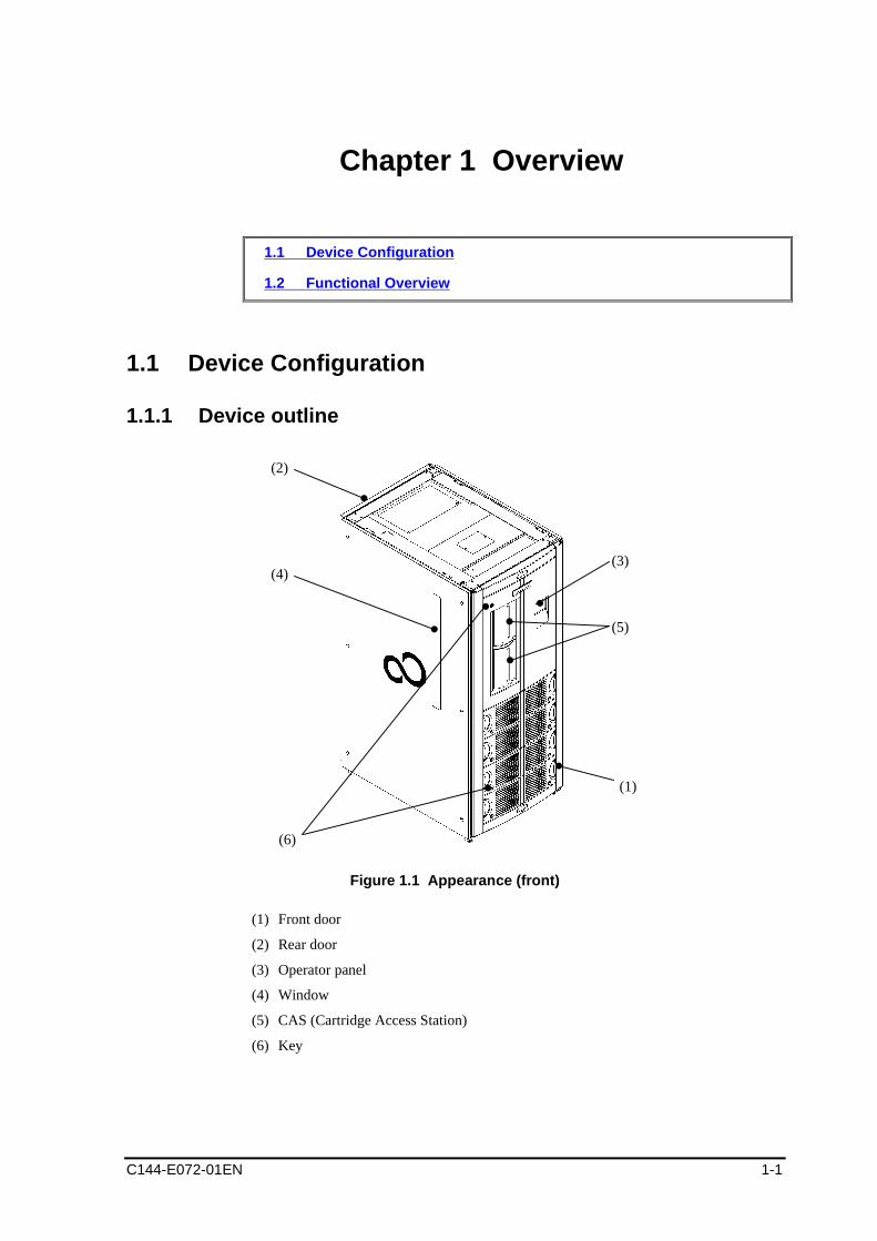
1.1.1 Device outline
(6)
(3)
(5)
(1)
(2)
(4)
Figure 1.1 Appearance (front)
(1) Front door
(2) Rear door
(3) Operator panel
(4) Window
(5) CAS (Cartridge Access Station)
(6) Key
Overview
1-2 C144-E072-01EN
(1)
(2)
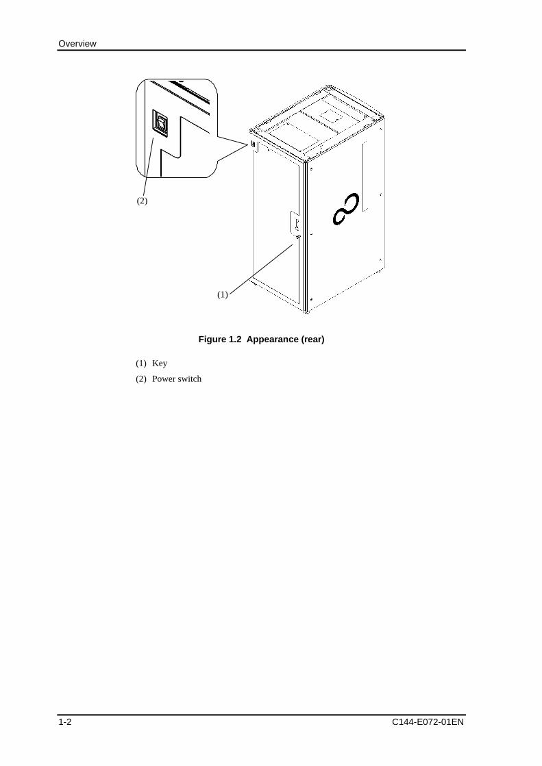
Figure 1.2 Appearance (rear)
(1) Key
(2) Power switch
1.1 Device Configuration
C144-E072-01EN 1-3
(1)
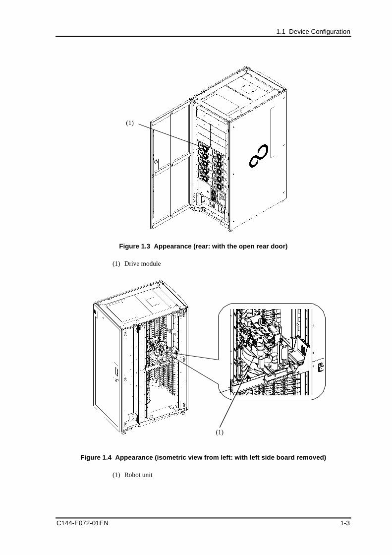
Figure 1.3 Appearance (rear: with the open rear door)
(1) Drive module
(1)
Figure 1.4 Appearance (isometric view from left: with left side board removed)
(1) Robot unit
Overview
1-4 C144-E072-01EN
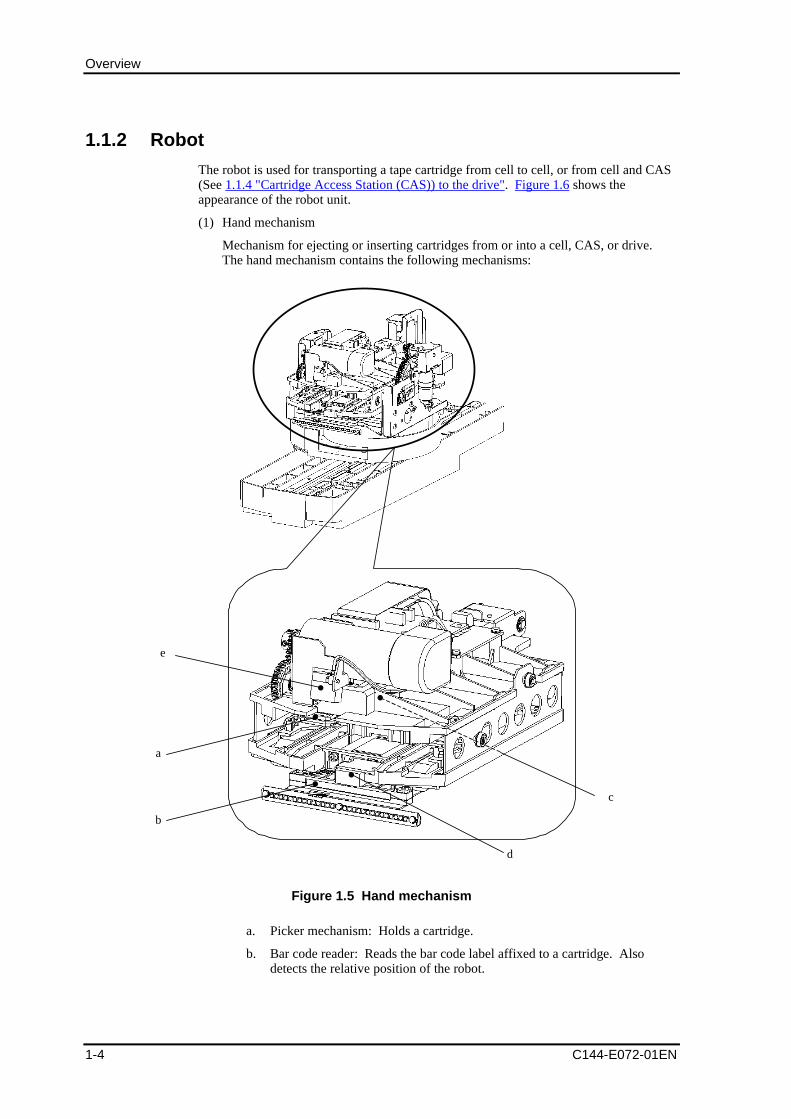
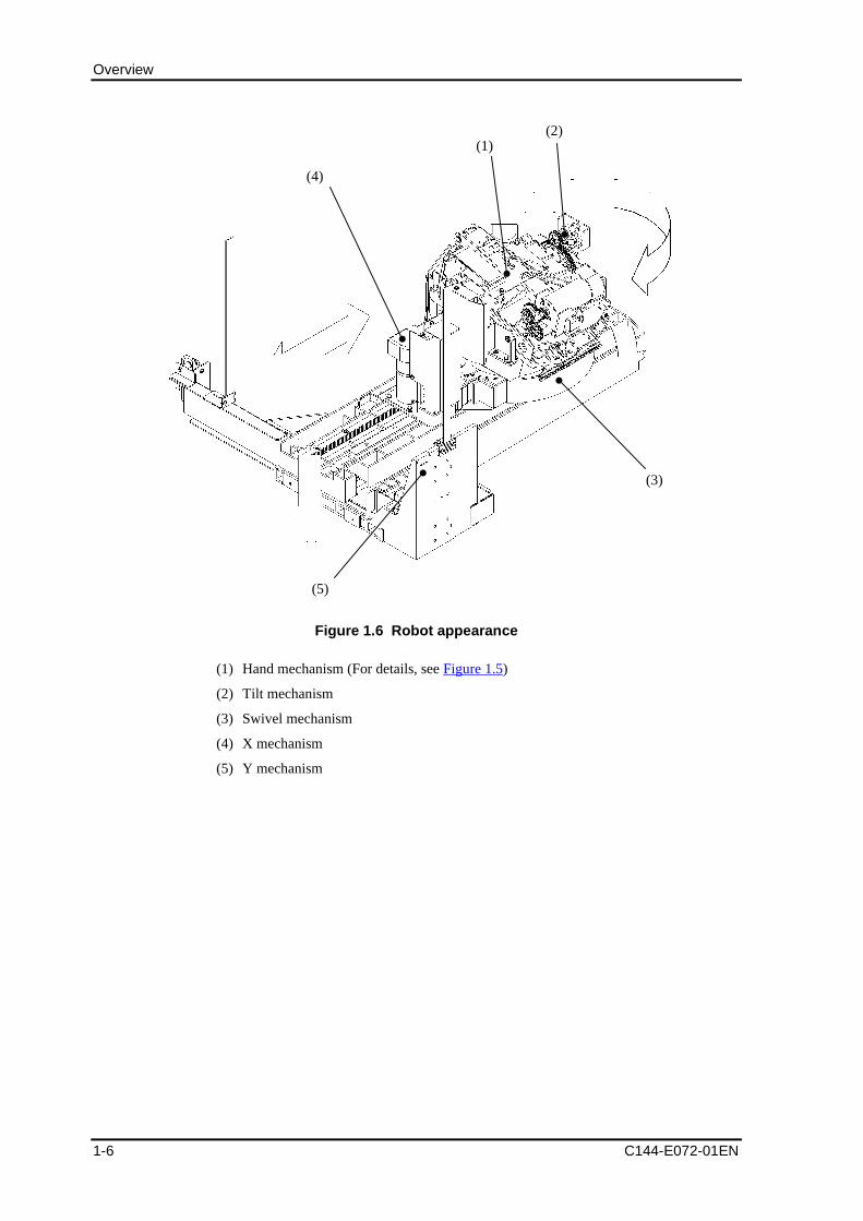
1.1.2 Robot
The robot is used for transporting a tape cartridge from cell to cell, or from cell and CAS(See 1.1.4 "Cartridge Access Station (CAS)) to the drive". Figure 1.6 shows theappearance of the robot unit.
(1) Hand mechanism
Mechanism for ejecting or inserting cartridges from or into a cell, CAS, or drive.The hand mechanism contains the following mechanisms:
c
a
e
b
d
Figure 1.5 Hand mechanism
a. Picker mechanism: Holds a cartridge.
b. Bar code reader: Reads the bar code label affixed to a cartridge. Alsodetects the relative position of the robot.
1.1 Device Configuration
C144-E072-01EN 1-5
c. CM reader: Reads the cartridge memory information contained in acartridge.
d. CIC sensor: Identifies whether a cartridge is in the cell, CAS, or drive.
e. CIP sensor: Indicates whether there is a cartridge in the hand mechanism.
(2) Tilt mechanism
Mechanism for tilting the hand mechanism to 0 degree and 12 degrees. This is amechanism for supporting the drive that is installed parallel to the cells that have atilt of 12 degrees, to prevent cartridges from protruding due, for example, to anearthquake.
(3) Swivel mechanism
Mechanism for rotating the hand mechanism. It is possible to rotate the handmechanism to match the orientation of the cell, CAS, and drive in the front, rear, andon both sides.
(4) X mechanism
Mechanism for operating the hand mechanism in the left/right direction. When theexpanded locker is used, an expanded base can be mounted on the left of the Xmechanism.
(5) Y mechanism
Mechanism for operating the robot unit vertically. A weight as heavy as the robotunit is mounted so that the robot unit can be moved vertically by hand (*1)
*1 The robot unit can be moved manually while it is turned off so that the robot can beset aside manually when, for example, numerous cartridges are inserted by openingthe front door for device installation. However, be sure to exercise caution whenhandling it. See Section 3.1.1, "Inserting/Ejecting a cartridge by opening the frontdoor."
Remarks:
When the device is installed, the robot unit is secured with metalbrackets to prevent damage during transport. Before using thedevice, ask our maintenance personnel to remove the brackets. Formore information about removing the brackets, see Section 2.1.2,"Removing the transport metal brackets."
Overview
1-6 C144-E072-01EN
Figure 1.6 Robot appearance
(1) Hand mechanism (For details, see Figure 1.5)
(2) Tilt mechanism
(3) Swivel mechanism
(4) X mechanism
(5) Y mechanism
(3)
(4)
(2)(1)
(5)
1.1 Device Configuration
C144-E072-01EN 1-7
1.1.3 Each component of the library
This section explains the physical location of each element in the library, namely, thecell, drive, and CAS (Cartridge Access Station) and their element addresses.
Remarks:
For information on the configuration diagram of each model, seeAppendix A, "Model Configuration."
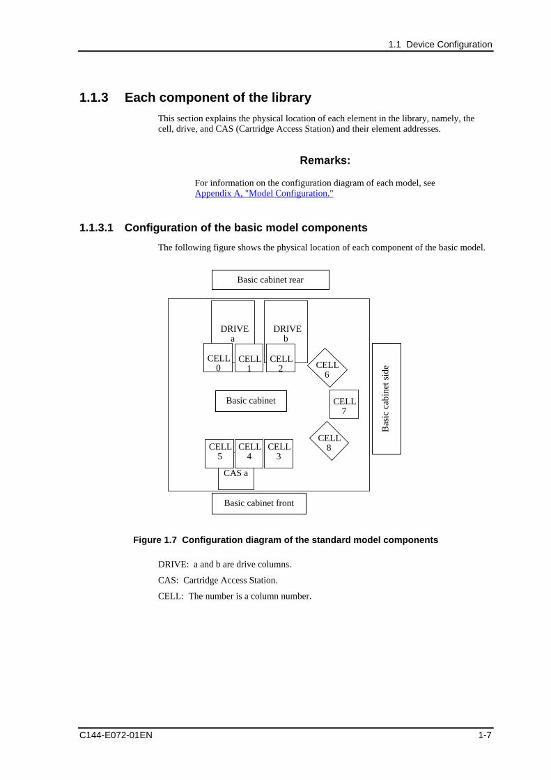
1.1.3.1 Configuration of the basic model components
The following figure shows the physical location of each component of the basic model.
Basic cabinet rear
Basic cabinet front
CELL7
CELL6
CELL8
DRIVEa
CAS a
DRIVEb
CELL5
CELL4
CELL0
CELL1
CELL2
CELL3
Bas
ic c
abin
et s
ide
Basic cabinet
Figure 1.7 Configuration diagram of the standard model components
DRIVE: a and b are drive columns.
CAS: Cartridge Access Station.
CELL: The number is a column number.
Overview
1-8 C144-E072-01EN
1.1.3.2 Special cells
In the library, there are special cells that cannot be accessed from the host.
The number of cells of each type depends on the model.
- COLUMN - 5
Includes the cleaning cell(5), replacement cell(1), reserve cell(2), and diagnosticcell(3).
- Cleaning cell
The cartridge for drive head cleaning is stored here. The auto-cleaning function ofthe library and the manual cleaning function on the operator panel use a cleaningcartridge in this cell.
- Replacement cell
This type of cell is used for temporarily storing a cartridge when a cartridgereplacement request (Exchange Medium command) is made from the host.
- Reserve cell
This type of cell is used for setting aside a cartridge when it cannot be stored in a cellin response to a cartridge mount request (Move Medium command) from the host.Open the front door to remove the cartridge set aside in the reserve cell.
When a cartridge is set aside in the reserve cell, the "Exist In Reserve Cell" icon inthe icon area of the operator panel lights.
- Diagnostic cell
This type of cell stores a special cartridge for diagnostics.
Notes:
Never take out any special cartridge contained in the diagnostic cellbecause it is used by the maintenance personnel.
1.1 Device Configuration
C144-E072-01EN 1-9
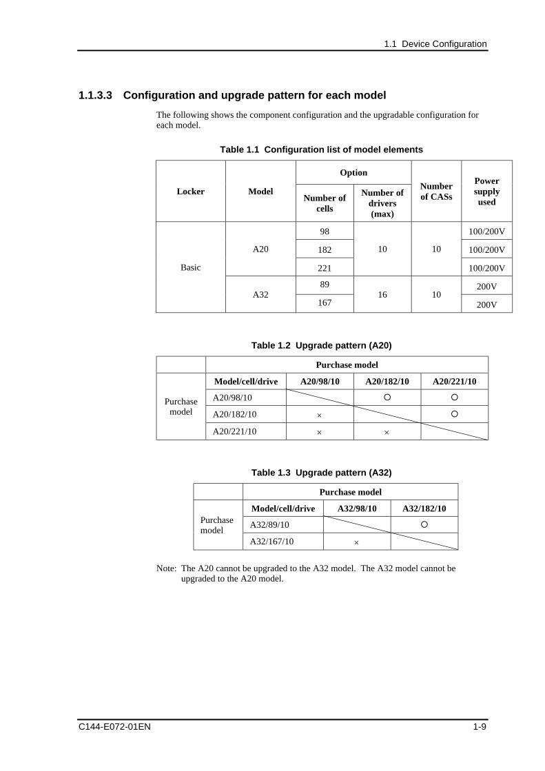
1.1.3.3 Configuration and upgrade pattern for each model
The following shows the component configuration and the upgradable configuration foreach model.
Table 1.1 Configuration list of model elements
Option
Locker ModelNumber of
cells
Number ofdrivers(max)
Numberof CASs
Powersupplyused
98 100/200V
182 100/200VA20
221
10 10
100/200V
89 200V
Basic
A32167
16 10200V
Table 1.2 Upgrade pattern (A20)
Purchase model
Model/cell/drive A20/98/10 A20/182/10 A20/221/10
A20/98/10
A20/182/10
Purchasemodel
A20/221/10
Table 1.3 Upgrade pattern (A32)
Purchase model
Model/cell/drive A32/98/10 A32/182/10
A32/89/10Purchasemodel
A32/167/10
Note: The A20 cannot be upgraded to the A32 model. The A32 model cannot beupgraded to the A20 model.
Overview
1-10 C144-E072-01EN
1.1.4 Cartridge Access Station (CAS)
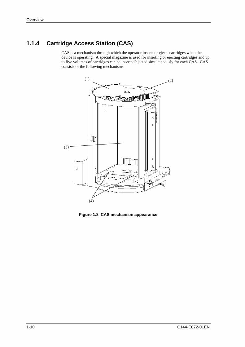
CAS is a mechanism through which the operator inserts or ejects cartridges when thedevice is operating. A special magazine is used for inserting or ejecting cartridges and upto five volumes of cartridges can be inserted/ejected simultaneously for each CAS. CASconsists of the following mechanisms.
(3)
(4)
(2)(1)
Figure 1.8 CAS mechanism appearance
1.1 Device Configuration
C144-E072-01EN 1-11
(1) External door
Door that covers the magazine insertion/ejection port. The external door is normallylocked by covering the magazine insertion/ejection port. The external door can beunlocked by using an operation from the operator panel so that a magazine can beinserted or ejected. By closing this door after inserting a magazine, an inventory ofthe magazine is made to manage information about cartridges in the magazine.
(2) Internal door
Safety door to screen off the operator from the device interior when no magazine isinserted in CAS
(3) Magazine insertion/ejection port
Port for inserting a magazine into the device or ejecting it from the device.
(4) Positioning projection
Projection with a tilt to position the magazine correctly in CAS
The following explains how to insert and eject a magazine using CAS.
1.1.4.1 Inserting a magazine from CAS
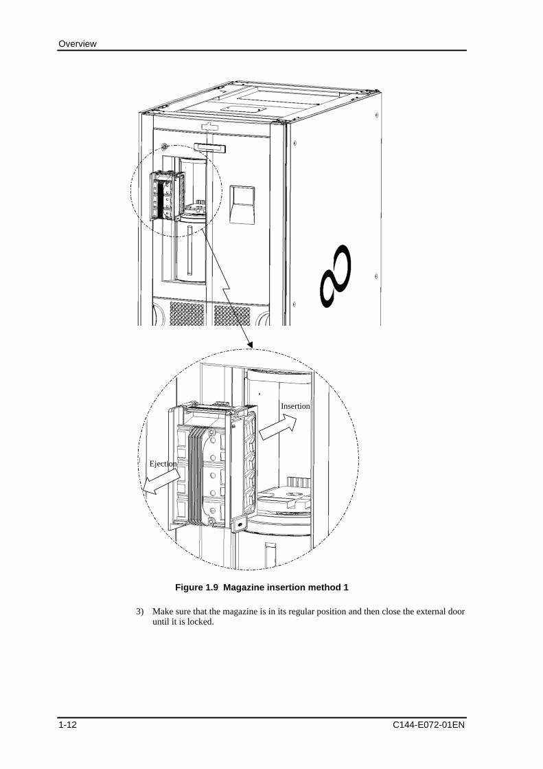
1) After the CAS external door is unlocked with an operation from the operator panel,the external door opens slightly. By hand, gently open the external door to the leftuntil you hear a click.
2) Holding the handle on the rear of the magazine, insert the magazine from themagazine insertion port into the CAS and push it into its normal position.
Overview
1-12 C144-E072-01EN
Ejection
Insertion
Figure 1.9 Magazine insertion method 1
3) Make sure that the magazine is in its regular position and then close the external dooruntil it is locked.
1.1 Device Configuration
C144-E072-01EN 1-13
Notes:
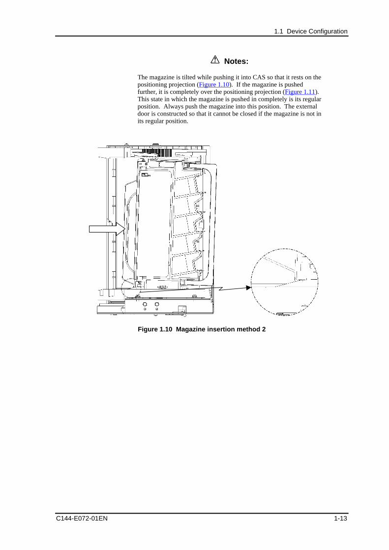
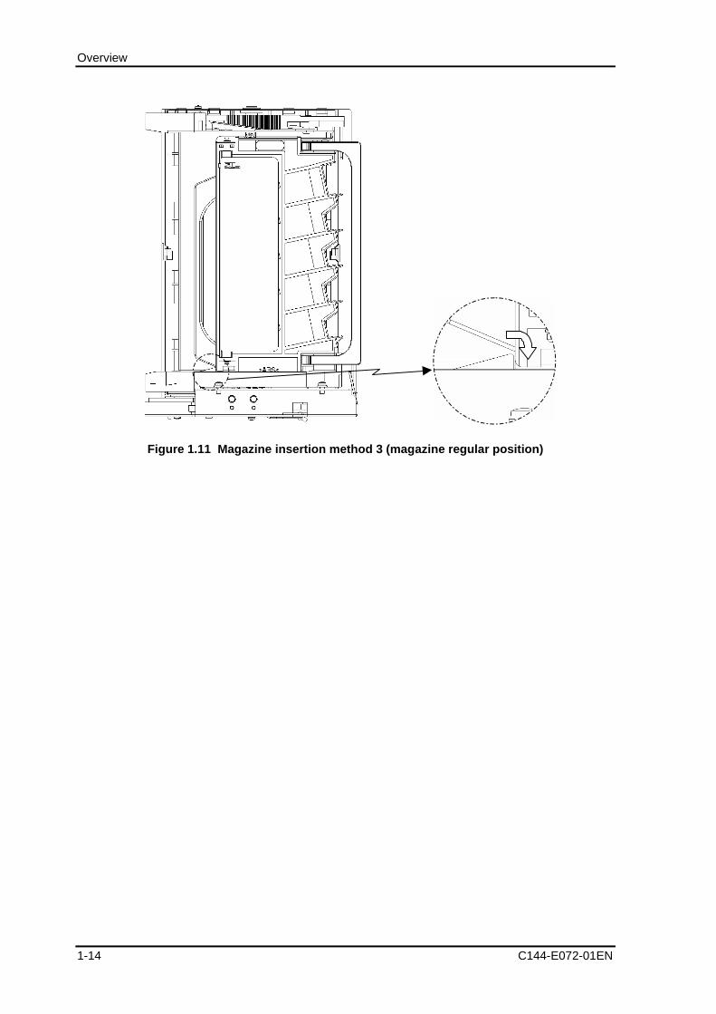
The magazine is tilted while pushing it into CAS so that it rests on thepositioning projection (Figure 1.10). If the magazine is pushedfurther, it is completely over the positioning projection (Figure 1.11).This state in which the magazine is pushed in completely is its regularposition. Always push the magazine into this position. The externaldoor is constructed so that it cannot be closed if the magazine is not inits regular position.
Figure 1.10 Magazine insertion method 2
Overview
1-14 C144-E072-01EN
Figure 1.11 Magazine insertion method 3 (magazine regular position)
1.1 Device Configuration
C144-E072-01EN 1-15
1.1.4.2 Ejecting a magazine from CAS
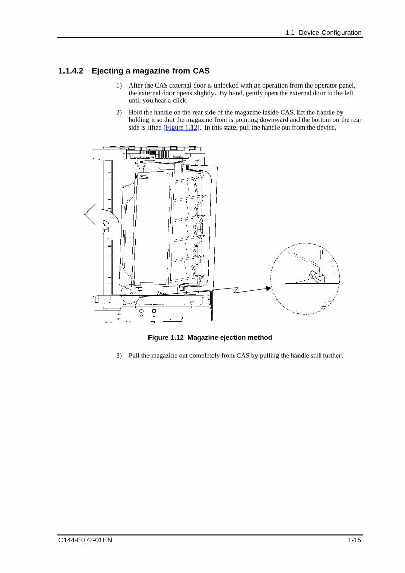
1) After the CAS external door is unlocked with an operation from the operator panel,the external door opens slightly. By hand, gently open the external door to the leftuntil you hear a click.
2) Hold the handle on the rear side of the magazine inside CAS, lift the handle byholding it so that the magazine front is pointing downward and the bottom on the rearside is lifted (Figure 1.12). In this state, pull the handle out from the device.
Figure 1.12 Magazine ejection method
3) Pull the magazine out completely from CAS by pulling the handle still further.
Overview
1-16 C144-E072-01EN
1.1.5 Magazine
The magazine is used as a shelf unit for receiving/delivering cartridges inside CAS whenthe operator inserts/ejects cartridges via CAS. The magazine has a 5-shelf unit for storingcartridges and up to five volumes of cartridges can be inserted/ejected simultaneouslyfrom CAS.
Remarks:
The library has two CASs, each of which can hold five-volumemagazines.
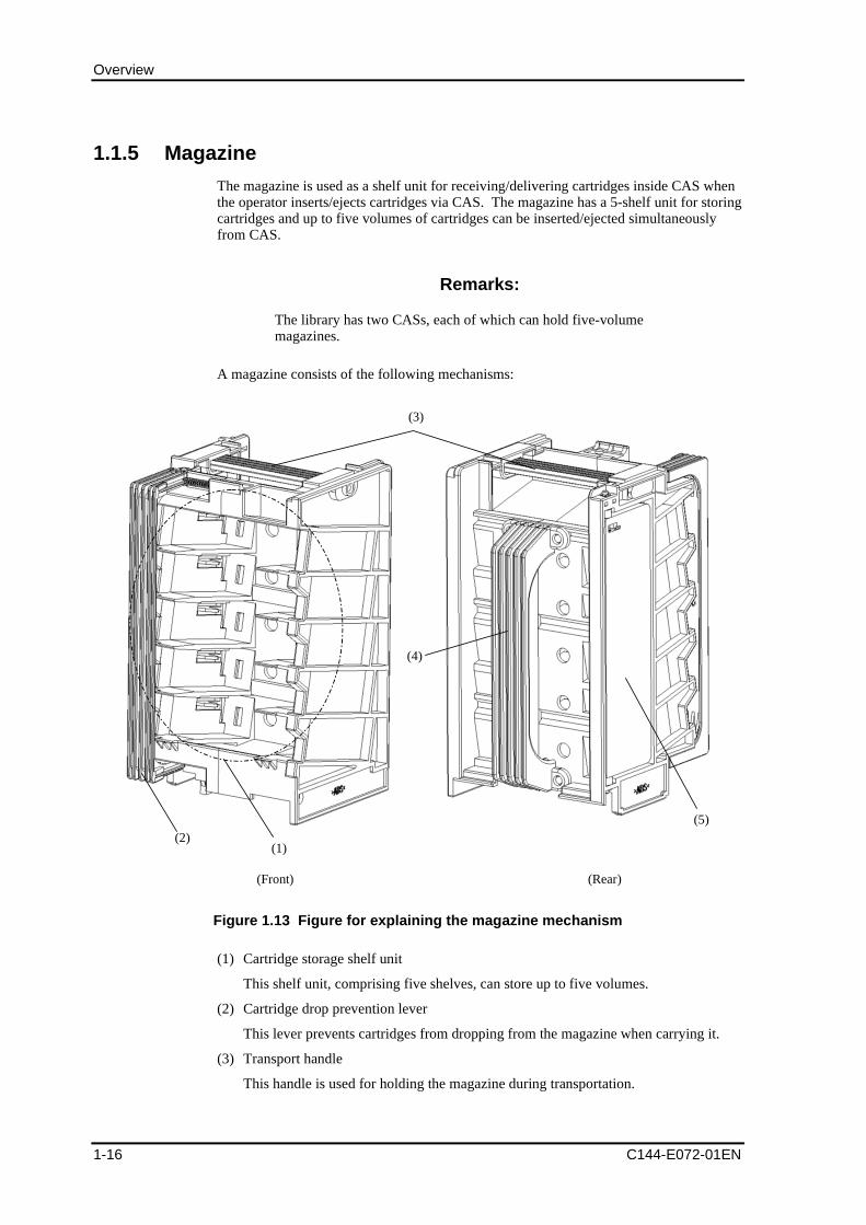
A magazine consists of the following mechanisms:
(2)
(3)
(4)
(5)
(1)
(Front) (Rear)
Figure 1.13 Figure for explaining the magazine mechanism
(1) Cartridge storage shelf unit
This shelf unit, comprising five shelves, can store up to five volumes.
(2) Cartridge drop prevention lever
This lever prevents cartridges from dropping from the magazine when carrying it.
(3) Transport handle
This handle is used for holding the magazine during transportation.
1.1 Device Configuration
C144-E072-01EN 1-17
(4) CAS insertion/ejection handle
This handle is used for pushing in/pulling out the magazine at insertion into orejection from CAS.
(5) Lever for preventing cartridges from being inserted backwards
Lever to keep cartridges from being inserted backwards. If an attempt is made toinsert a cartridge into the magazine with the cartridge having the wrong orientation,this lever is extended, making insertion into the CAS physically impossible.
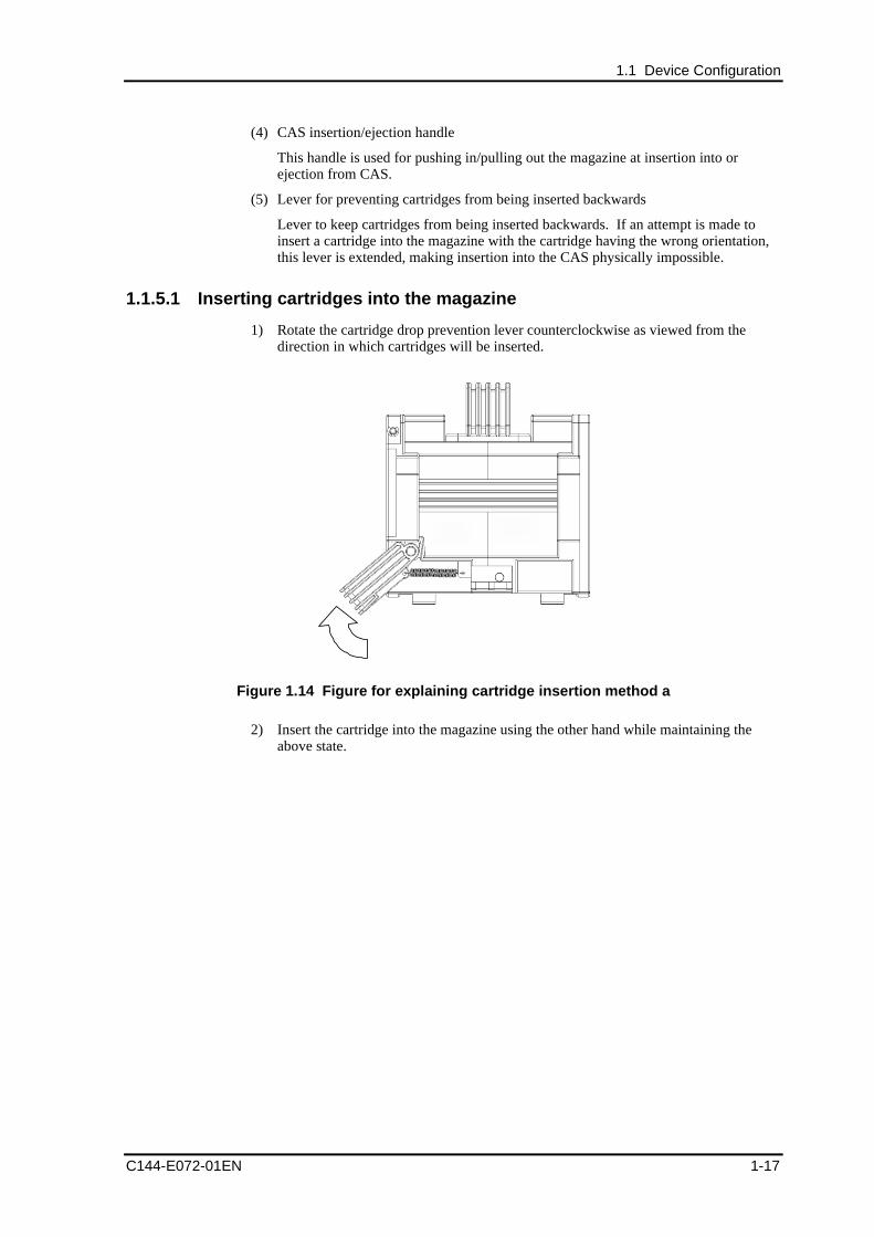
1.1.5.1 Inserting cartridges into the magazine
1) Rotate the cartridge drop prevention lever counterclockwise as viewed from thedirection in which cartridges will be inserted.
Figure 1.14 Figure for explaining cartridge insertion method a
2) Insert the cartridge into the magazine using the other hand while maintaining theabove state.
Overview
1-18 C144-E072-01EN
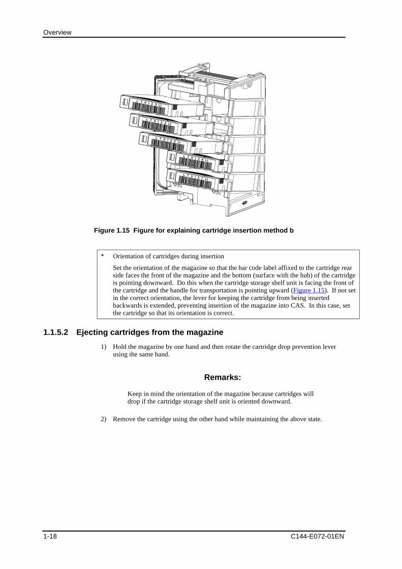
Figure 1.15 Figure for explaining cartridge insertion method b
* Orientation of cartridges during insertion
Set the orientation of the magazine so that the bar code label affixed to the cartridge rearside faces the front of the magazine and the bottom (surface with the hub) of the cartridgeis pointing downward. Do this when the cartridge storage shelf unit is facing the front ofthe cartridge and the handle for transportation is pointing upward (Figure 1.15). If not setin the correct orientation, the lever for keeping the cartridge from being insertedbackwards is extended, preventing insertion of the magazine into CAS. In this case, setthe cartridge so that its orientation is correct.
1.1.5.2 Ejecting cartridges from the magazine
1) Hold the magazine by one hand and then rotate the cartridge drop prevention leverusing the same hand.
Remarks:
Keep in mind the orientation of the magazine because cartridges willdrop if the cartridge storage shelf unit is oriented downward.
2) Remove the cartridge using the other hand while maintaining the above state.
1.1 Device Configuration
C144-E072-01EN 1-19
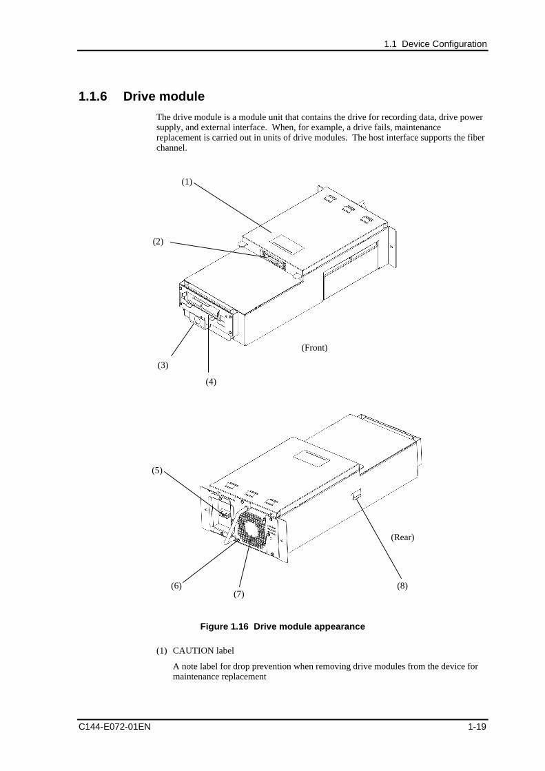
1.1.6 Drive module
The drive module is a module unit that contains the drive for recording data, drive powersupply, and external interface. When, for example, a drive fails, maintenancereplacement is carried out in units of drive modules. The host interface supports the fiberchannel.
(1)
(2)
(3)
(4)
(Front)
(5)
(6)(7)
(8)
(Rear)
Figure 1.16 Drive module appearance
(1) CAUTION label
A note label for drop prevention when removing drive modules from the device formaintenance replacement
Overview
1-20 C144-E072-01EN
(2) Connection connector
Connector for connecting a drive module and the main unit of the device. Thisconnector is used for information management and power supply of the drive.
(3) Relative position flag
Mark for inserting cartridges into the drive with the robot.
Remarks:
Note that the robot may not be able to insert cartridges into the drivecorrectly due to deformation or dust adherence.
(4) Drive
Drive for recording data. The drive may fail if anything other than cartridges (e.g., ahand) is inserted into the CTG insertion port when handling the drive module.
(5) Interface
Port for the fiber channel interface.
(6) Handle
Handle used for removing or transporting drive modules.
(7) Fan
Fan for cooling the interior of the drive module
(8) Stopper for drop prevention
Stopper for preventing the drive module from dropping when pulling it out from thedevice for drive module maintenance, etc.
CAUTIONInjury: Never move your hands away from the drive module until itis placed in a safe place. Otherwise, the drive module may drop,causing injury if you move your hands away from it after pulling itout beyond this stopper.
1.1 Device Configuration
C144-E072-01EN 1-21
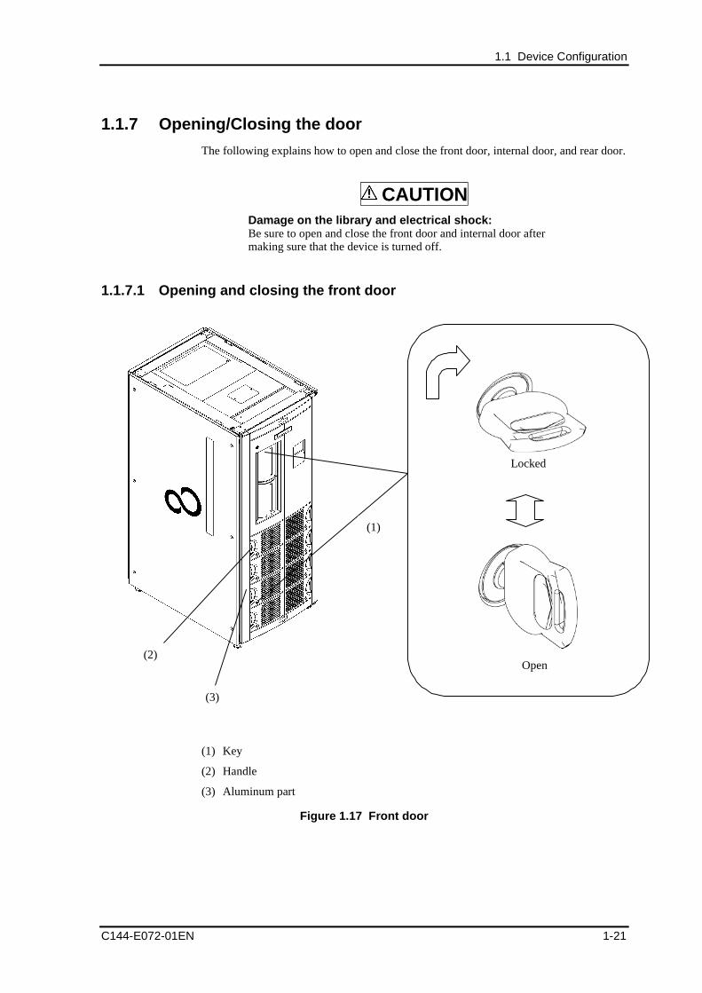
1.1.7 Opening/Closing the door
The following explains how to open and close the front door, internal door, and rear door.
CAUTIONDamage on the library and electrical shock:Be sure to open and close the front door and internal door aftermaking sure that the device is turned off.
1.1.7.1 Opening and closing the front door
Locked
Open(2)
(3)
(1)
(1) Key
(2) Handle
(3) Aluminum part
Figure 1.17 Front door
Overview
1-22 C144-E072-01EN
(1) Opening the front door
1) Turn to the open position the keys in the locked position at the upper and lower partsof the front door (two locations).
2) Open the front door by pulling the handle out.
(2) Closing the front door
1) Close the front door by pressing the aluminum part at the left end of the front door.
2) Turn the keys from the open position to the locked position (two locations) at theupper and lower parts of the front door.
Remarks:
1. When opening or closing the front door, do not hold any partother than the handle and aluminum part.
2. Open and close the front door slowly.
3. When closing the front door, make sure that the two keys are inthe locked position.
1.1 Device Configuration
C144-E072-01EN 1-23
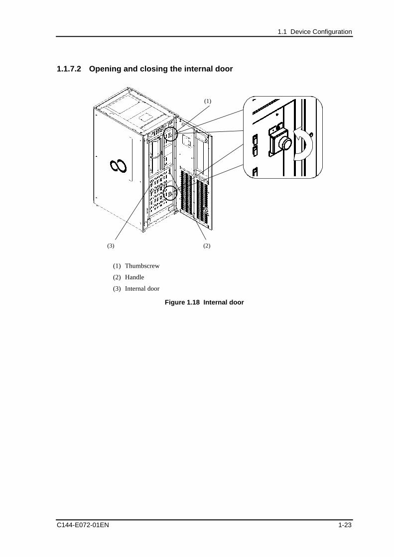
1.1.7.2 Opening and closing the internal door
(1)
(2)(3)
(1) Thumbscrew
(2) Handle
(3) Internal door
Figure 1.18 Internal door
Overview
1-24 C144-E072-01EN
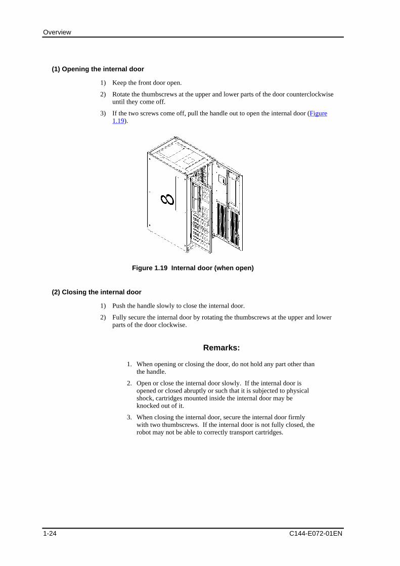
(1) Opening the internal door
1) Keep the front door open.
2) Rotate the thumbscrews at the upper and lower parts of the door counterclockwiseuntil they come off.
3) If the two screws come off, pull the handle out to open the internal door (Figure1.19).
Figure 1.19 Internal door (when open)
(2) Closing the internal door
1) Push the handle slowly to close the internal door.
2) Fully secure the internal door by rotating the thumbscrews at the upper and lowerparts of the door clockwise.
Remarks:
1. When opening or closing the door, do not hold any part other thanthe handle.
2. Open or close the internal door slowly. If the internal door isopened or closed abruptly or such that it is subjected to physicalshock, cartridges mounted inside the internal door may beknocked out of it.
3. When closing the internal door, secure the internal door firmlywith two thumbscrews. If the internal door is not fully closed, therobot may not be able to correctly transport cartridges.
1.1 Device Configuration
C144-E072-01EN 1-25
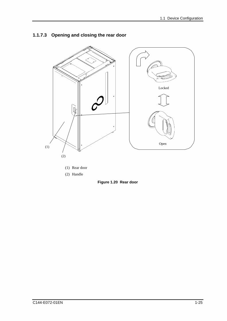
1.1.7.3 Opening and closing the rear door
Locked
Open
(2)
(1)
(1) Rear door
(2) Handle
Figure 1.20 Rear door
Overview
1-26 C144-E072-01EN
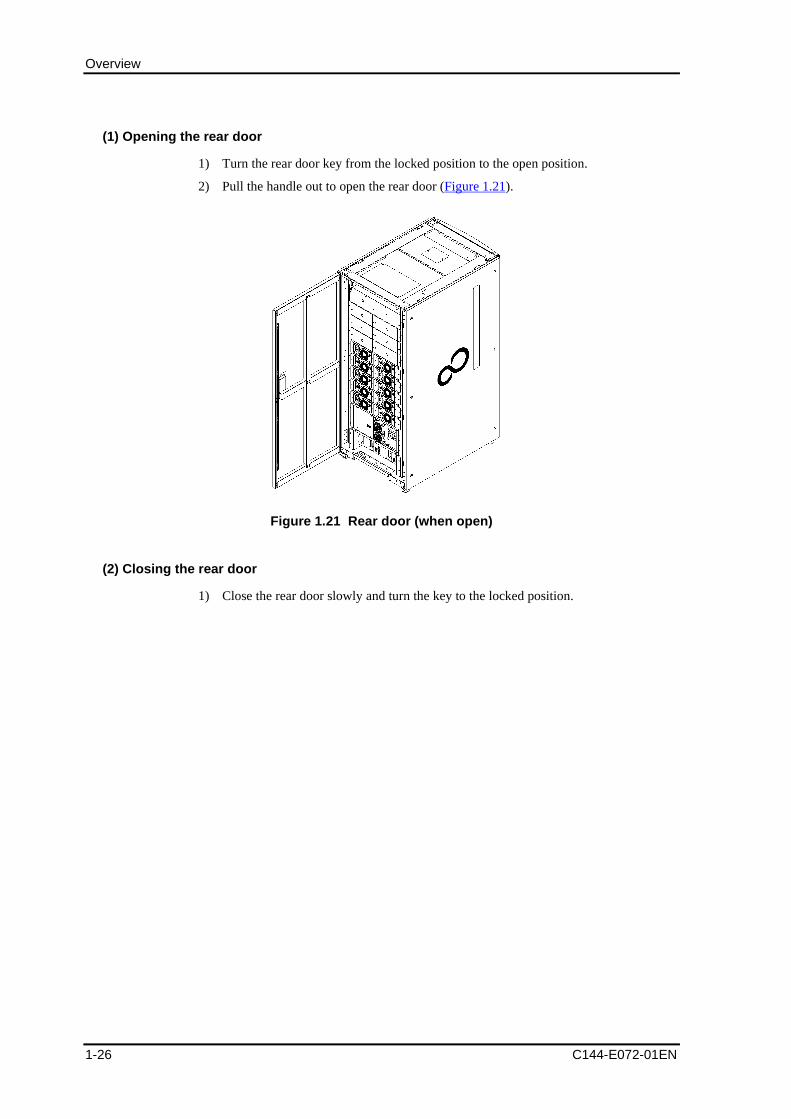
(1) Opening the rear door
1) Turn the rear door key from the locked position to the open position.
2) Pull the handle out to open the rear door (Figure 1.21).
Figure 1.21 Rear door (when open)
(2) Closing the rear door
1) Close the rear door slowly and turn the key to the locked position.
1.1 Device Configuration
C144-E072-01EN 1-27
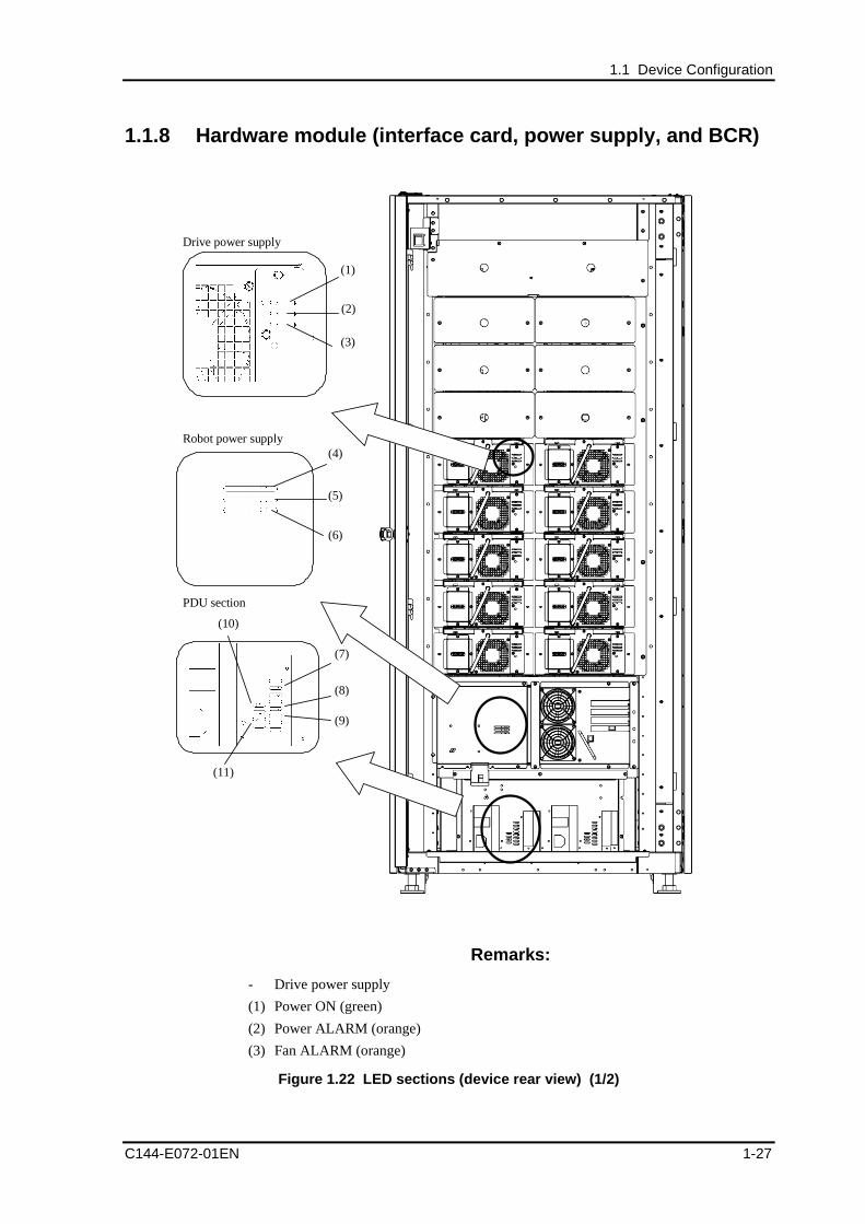
1.1.8 Hardware module (interface card, power supply, and BCR)
(1)
(2)
(11)
(10)
(9)
(8)
(7)
(6)
(5)
(4)
(3)
Drive power supply
Robot power supply
PDU section
Remarks:
- Drive power supply
(1) Power ON (green)
(2) Power ALARM (orange)
(3) Fan ALARM (orange)
Figure 1.22 LED sections (device rear view) (1/2)
Overview
1-28 C144-E072-01EN
- Robot power supply
(4) Power ON (green)
(5) Power ALARM (orange)
(6) Fan ALARM (orange)
- PDU section
(7) Power ON (green)
(8) Robot side ALARM (orange)
(9) Drive side ALARM (orange)
(10)Robot side ON (green)
(11)Drive side ON (green)
Figure 1.22 LED sections (device rear view) (2/2)
(1)
(2)
(3)
(5)(4)
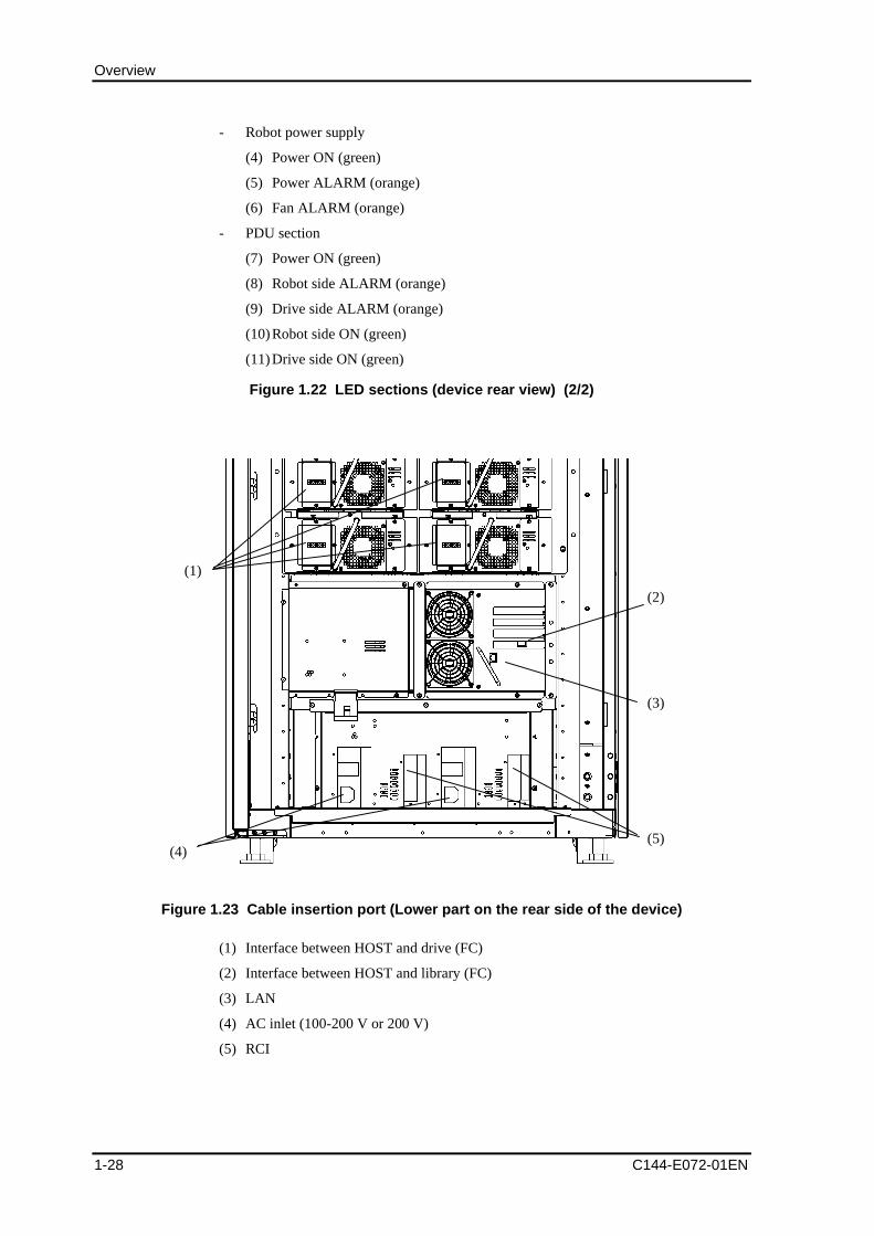
Figure 1.23 Cable insertion port (Lower part on the rear side of the device)
(1) Interface between HOST and drive (FC)
(2) Interface between HOST and library (FC)
(3) LAN
(4) AC inlet (100-200 V or 200 V)
(5) RCI
1.2 Functional Overview
C144-E072-01EN 1-29
1.2 Functional OverviewThis section explains the functions provided by the magnetic tape library device (referredto as the library hereafter).
1.2.1 FC control function
The library is controlled by software that controls a magnetic tape library device, such asbackup software (collectively referred to as backup software hereafter).
The library is connected via the Fibre Channel (FC) interface to a server (such as Solarisand WindowsNT4.0/2000) on which the backup software is installed.
The backup software, through the Fibre Channel interface, requests the robot to transportcartridges to the drive or requests the drive to access data.
Remarks:
The library can have up to four connection ports for the SCSI or fiberchannel cables. To add a connection port, consult with themaintenance person.
1.2.2 Fast load function
This is a function only for mounting a cartridge in response to a request from the host tomount a cartridge on the drive without waiting until the drive is ready.
The fast load function can be set from the operator panel. For details on how to set thefunction, see 4.5.2, "Setting library information."
Important:
Depending on the backup software, the fast load function may not beusable. For more information, check the backup softwarespecifications (The factory default for the fast load function is"disabled").
Important:
If the fast load function is disabled, a timeout may occur for somekinds of backup software. Check the backup software that is beingused to ensure that the timeout period can be changed.
Overview
1-30 C144-E072-01EN
1.2.3 Inventory function
This is a function for updating cartridge management information by reading the bar codelabels affixed to the cartridges inside the library. The inventory function is used in thefollowing cases:
- When the library is turned on (only if the auto-inventory function is "enabled")
- When the inventory is operated from the operator panel
- When the front door is opened and closed to insert or eject a large number ofcartridges.
Remarks:
For details on how to make an inventory from the operator panel, see4.13, "Making an inventory."
Auto-inventory function
This is a function for making an inventory as an initialization operation when the libraryis turned on.
Disabling the auto-inventory function can reduce the library startup time. However, ifyou insert or eject a cartridge with the front door open after turning off the library, theinformation is not automatically reflected in the management information of the library.If you use the library in this state, the library may malfunction (The factory default for theauto-inventory function is "enabled").
Remarks:
If you turn off the library, open the front door, and change theposition of a cartridge that is not a CAS cartridge while the auto-inventory function is disabled, be sure to take inventory from theoperator panel.
1.2 Functional Overview
C144-E072-01EN 1-31
1.2.4 Manual load function
This is a function for loading cartridges directly to the drive from CAS or to unload themdirectly from the drive to CAS without using backup software.
To load a cartridge to the drive or to unload it from the drive manually, perform theLoad/Unload operation on the operator panel.
Remarks:
1. For information on the method of inserting a magazine into CAS,see 3.1.2, "Inserting/Ejecting cartridges from CAS."
2. For information on the method of performing the Load/Unloadoperation from the operator panel, see 4.7, "Loading/Unloading aCartridge."
1.2.5 Cleaning function
This library has both an automatic and a manual cleaning function for cleaning drives.Both functions use the cleaning cartridge stored in the cleaning cell.
Neither the auto-cleaning function nor the manual cleaning function can be used if thereis no cleaning cartridge in the cleaning cell. If there is no cleaning cartridge in the cell,insert a cleaning cartridge from the CAS. This operation can be performed from theoperator panel. For information on inserting a cleaning cartridge, see 4.9.1, "Inserting acleaning cartridge."
Operation of the auto-cleaning function and manual cleaning function are described in thefollowing sections.
1.2.5.1 Auto-cleaning function
If the library detects that the drive requires cleaning, the drive is automatically cleaned byusing the cleaning cartridge in the cleaning cell.
Remarks:
1. It is necessary to "enable" the auto-cleaning function on theoperator panel or remote panel.
2. If the auto-cleaning function is "disabled", auto-cleaning is notperformed even if the drive requires cleaning.
In that case, perform drive cleaning using the manual cleaningfunction or the cleaning function of the backup software.
Overview
1-32 C144-E072-01EN
Important:
Generally, the auto-cleaning function of the backup software iscontrolled by the processing time of the library. Therefore, cleaningmore often than necessary may be done, causing the cleaningcartridge to reach the end of its service life earlier than normal.Furthermore, the auto-cleaning function of the backup software usesordinary cells, reducing the cells available for data cartridges. Fujitsutherefore recommends using the auto-cleaning function under controlof the library (the factory default is "enabled").
1.2.5.2 Manual cleaning function
The drive is cleaned directly by operations on the operator panel.
For information on the method of performing the manual cleaning from the operatorpanel, see 4.8, "Cleaning the Drive Manually."
1.2 Functional Overview
C144-E072-01EN 1-33
1.2.6 Functions for recovery
This library takes into account settings and operations for recovery corresponding toerrors of the drive, library, and server.
1.2.6.1 Recovery method when a drive error occurs
If an error occurs in the drive during initialization or when a cartridge is loaded, "Error" isdisplayed in the "Drive Status" field on the Device Status window (home window) of theoperator panel or remote panel. Recovery can be made possible by releasing the driveerror by the reset operation on the operator panel and unloading the loaded cartridge intothe original cell.
Important:
If the drive error cannot be released by the reset operation on theoperator panel, contact the maintenance person.
1.2.6.2 Recovery method when a library error occurs
If the library detects a hardware error during initialization or when a cartridge istransported, "Error" is displayed in the "Library Status" field on the Device Statuswindow (home window) of the operator panel or remote panel and also the Library Erroricon is displayed in the icon area. Recovery can be made possible by releasing the libraryerror by performing the reset operation on the operator panel.
Important:
If the library error cannot be released by the reset operation on theoperator panel, contact the maintenance person.
1.2.6.3 Operation to be performed when the host goes down and a cartridgeremaining in the drive should be unloaded
If a cartridge is loaded into the drive by backup software and the host goes down or anerror occurs in the interface with the library, it becomes impossible to unload thecartridge by the backup software.
In that case, the cartridge that is loaded in the drive can be forced to be unloaded backinto the original cell by using the manual eject function of the library.
The manual eject function can be performed by a manual eject operation on the operatorpanel.
Overview
1-34 C144-E072-01EN
Remarks:
For information on the method of operating the manual ejection fromthe operator panel, see 4.12, "Unloading a Cartridge Loaded from theHost."
CAUTION
Data loss: Do not perform this operation when the host accessesthe drive normally. Otherwise, an error may occur in the drive path.
1.2.6.4 Auto-eject function
This function can unload all cartridges already loaded in the drive when the library isturned on (*1).
*1 It is necessary to "enable" the auto-eject function on the operator panel.
Important:
During automatic unloading by the library, an inconsistency in thecartridge management information may be detected, depending on thebackup software.If that type of backup software is used, perform the inventoryoperation of the backup software and update the managementinformation of cartridge after "disabling" the auto-eject setting.
1.2.7 Remote panel function
This function can monitor the library and drive information via LAN from the generalbrowser (such as Internet Explorer and Netscape) using the remote communicationfunction of the library. It can also be used to set the operations and functions of thelibrary and drive and to perform the cleaning function of the drive.
The remote panel is protected by the login password so that unauthorized access to it canbe prevented. General passwords and administrator passwords are available.
- Login using a general password
It is allowed to monitor the states of the library, drive, and tape and to reference thesetup information.
- Login using an administrator password
In addition to the functions logged in with a general password, operations such as theoperation settings, functional settings, and cleaning can be performed.
1.2 Functional Overview
C144-E072-01EN 1-35
Remarks:
1. To use the remote panel, it is necessary to make network settingsin advance from the operator panel. For information on themethods of network settings and operating the remote panel, see5, "Remote Panel Operation."
2. The recommended browser is Microsoft Internet Explorer 5.0 to6.0 and Netscape Navigator 4.7 to 4.78.
3. The remote panel uses "Cookie" and "Java Script". Enable thesettings of these functions of the browser to be used.
Important:
Use the remote panel in an environment in which sufficient networksecurity measures are taken.
1.2.8 E-mail function
The E-mail function is available as a remote communication function of the library.
This function can send the error report E-mail containing error information is written toup to five mail addresses when a library or drive error occurs. The E-mail function canbe set on the remote panel.
For information on the method of sending mail from the remote panel, see 5.5.5, " Settingthe E-mail Function."
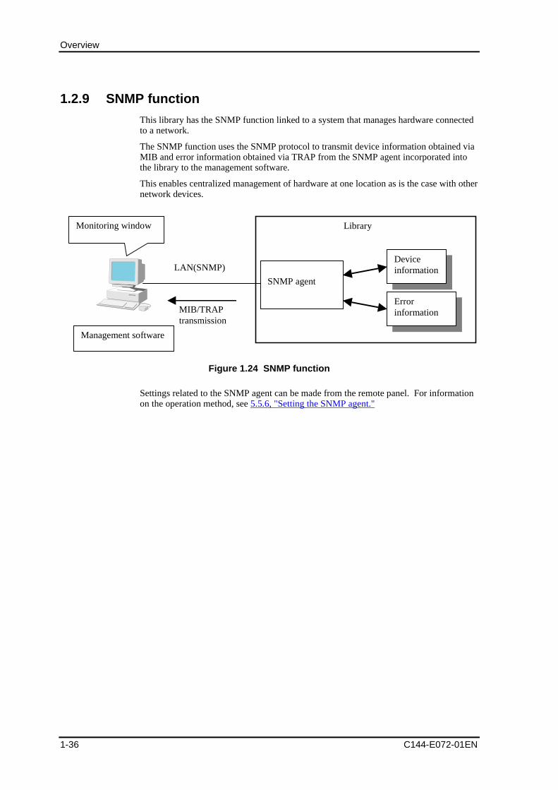
Overview
1-36 C144-E072-01EN
1.2.9 SNMP function
This library has the SNMP function linked to a system that manages hardware connectedto a network.
The SNMP function uses the SNMP protocol to transmit device information obtained viaMIB and error information obtained via TRAP from the SNMP agent incorporated intothe library to the management software.
This enables centralized management of hardware at one location as is the case with othernetwork devices.
Library
SNMP agent
Monitoring window
Deviceinformation
Management software
LAN(SNMP)
ErrorinformationMIB/TRAP
transmission
Figure 1.24 SNMP function
Settings related to the SNMP agent can be made from the remote panel. For informationon the operation method, see 5.5.6, "Setting the SNMP agent."
C144-E072-01EN 2-1
Chapter 2 Introducing and Preparing theLibrary
2.1 Installing the Library
2.2 Preparing the Host Installation
2.3 Connecting the Library
2.4 Power-on and Power-off
2.5 Checking the Library and Drive Settings
2.6 Checking the Host Settings
2.1 Installing the Library
2.1.1 Conditions for library installation
In addition to the installation space of the device, space is required for opening andclosing the front and rear doors.
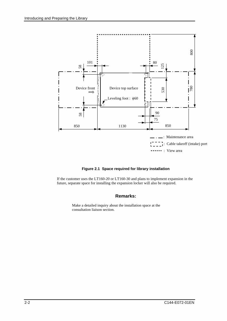
Introducing and Preparing the Library
2-2 C144-E072-01EN
1130
780
75
90
530
125
850 850
80101
5858
Leveling foot : 60
Device front
: Maintenance area
: Cable takeoff (intake) port
Device top surface
800
: View area
Figure 2.1 Space required for library installation
If the customer uses the LT160-20 or LT160-30 and plans to implement expansion in thefuture, separate space for installing the expansion locker will also be required.
Remarks:
Make a detailed inquiry about the installation space at theconsultation liaison section.
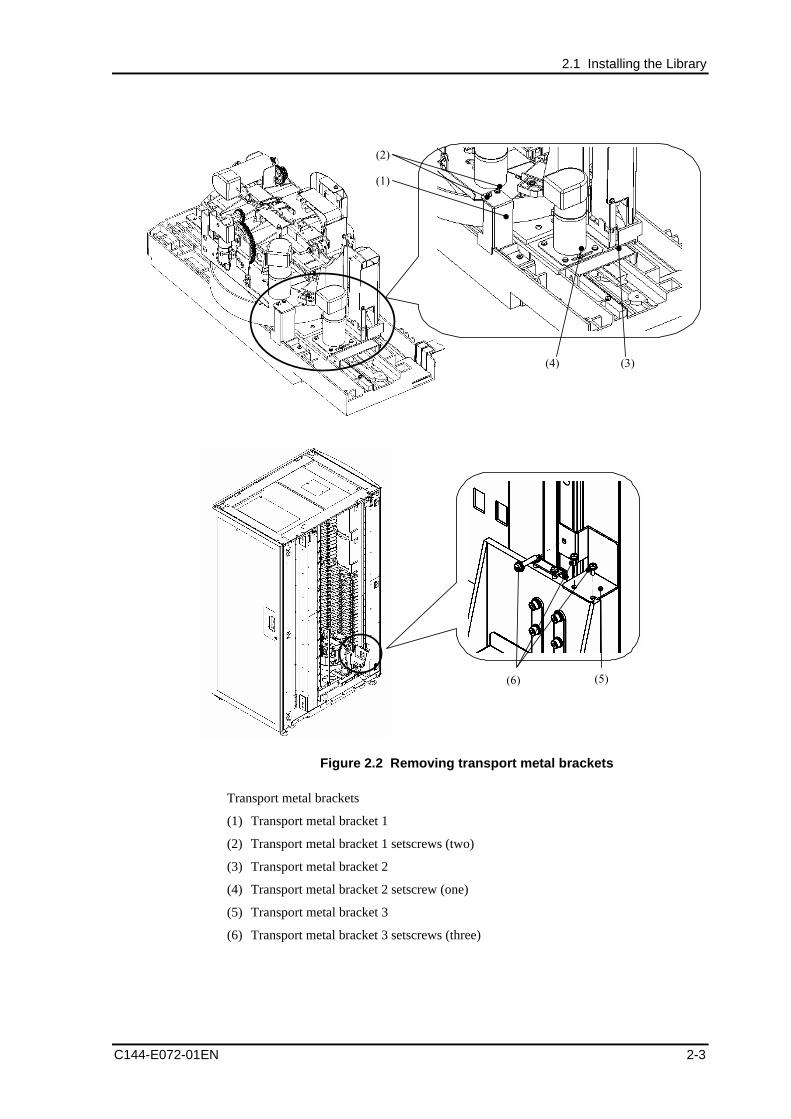
2.1 Installing the Library
C144-E072-01EN 2-3
(1)
(2)
(3)(4)
(5)(6)
Figure 2.2 Removing transport metal brackets
Transport metal brackets
(1) Transport metal bracket 1
(2) Transport metal bracket 1 setscrews (two)
(3) Transport metal bracket 2
(4) Transport metal bracket 2 setscrew (one)
(5) Transport metal bracket 3
(6) Transport metal bracket 3 setscrews (three)
Introducing and Preparing the Library
2-4 C144-E072-01EN
2.2 Preparing the Host InstallationThis section explains how to prepare for host installation.
Refer to the "Setup Guide" provided with the library for information about the settings forthe host, OS, driver, software, and hardware required to use the library.
Remarks:
A host, host bus adapter, FC switch, or other devices to be connectedto the library must be ones that support the library.
1) Turn on the host and then install software or a driver or both software and driver thatare compatible with the library.
2) Turn off all peripheral devices that are connected to the host computer using methodsappropriate for each case.
3) Turn off the host. If the host computer is connected to a network, contact the systemadministrator before turning off the power.
Remarks:
1. Make sure that as many card extension slots as appropriate thatcan be used in the library model to be used are mounted in thehost computer.
2. Make sure that the host bus adapter card is supported by thebackup software application to be used.
3. To install the library on the same FC bus as other devices, checkthe target IDs (LOOP IDs) that can be used. If you suspect thatthe library has the same ID as another drive, you need to changethe target ID from the operator panel.
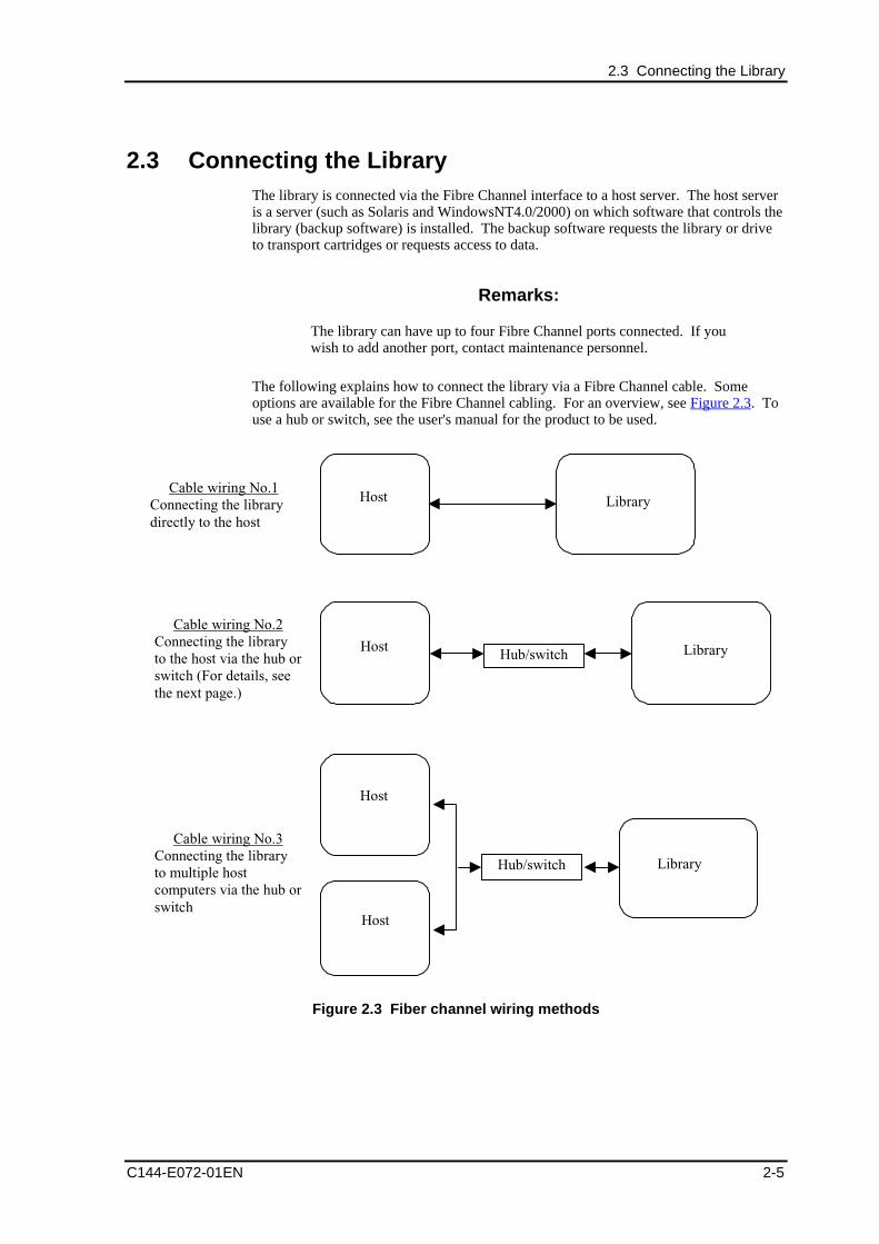
2.3 Connecting the Library
C144-E072-01EN 2-5
2.3 Connecting the LibraryThe library is connected via the Fibre Channel interface to a host server. The host serveris a server (such as Solaris and WindowsNT4.0/2000) on which software that controls thelibrary (backup software) is installed. The backup software requests the library or driveto transport cartridges or requests access to data.
Remarks:
The library can have up to four Fibre Channel ports connected. If youwish to add another port, contact maintenance personnel.
The following explains how to connect the library via a Fibre Channel cable. Someoptions are available for the Fibre Channel cabling. For an overview, see Figure 2.3. Touse a hub or switch, see the user's manual for the product to be used.
Cable wiring No.1Connecting the librarydirectly to the host
Host
Host Library
Host
Library
Host
Hub/switch
Hub/switch
Cable wiring No.2Connecting the libraryto the host via the hub orswitch (For details, seethe next page.)
Cable wiring No.3Connecting the libraryto multiple hostcomputers via the hub orswitch
Library
Figure 2.3 Fiber channel wiring methods
Introducing and Preparing the Library
2-6 C144-E072-01EN
The following procedure explains the wiring of fiber channels among the host,hub/switch, and library.
Remarks:
To use a hub or switch, see the user's manual for the product to beused.
1) Make sure that the library and host are not active and the library is not connected tothe host.
2) Make sure that the required software is installed.
3) Turn off the hub or FC switch. If the host is connected to a network, contact thesystem administrator before turning off the power.
4) Mount the host adapter on the host computer. To prevent electrostatic discharge(ESD), follow the correct procedure. When removing an internal component, be sureto wear the antistatic wrist strap and use the antistatic mat.
5) Connect the FC interface (or interfaces) of the library to the host, hub, or switch.
6) If there is an FC switch, turn it on.
7) Connect the power cord of the library to a grounded power outlet. Turn on thelibrary by pressing the library's power switch. Turning on the power startsinitialization. After some minutes, the home window opens, displaying the library'soperator panel. In the home window, the status of the drive and of the library aredisplayed.
Remarks:
If a model has two power sources, do not connect the two powercords to one service outlet (power strip).
8) Set Fibre Channel from the operator panel. For the items that must be set, see 2.5,"Checking the Library and Drive Settings."
9) Turn on the host.
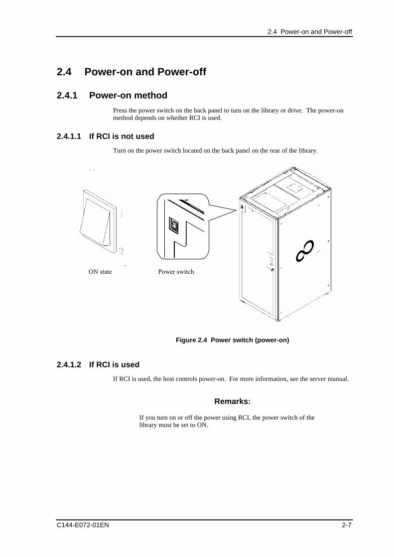
2.4 Power-on and Power-off
C144-E072-01EN 2-7
2.4 Power-on and Power-off
2.4.1 Power-on method
Press the power switch on the back panel to turn on the library or drive. The power-onmethod depends on whether RCI is used.
2.4.1.1 If RCI is not used
Turn on the power switch located on the back panel on the rear of the library.
Power switchON state
Figure 2.4 Power switch (power-on)
2.4.1.2 If RCI is used
If RCI is used, the host controls power-on. For more information, see the server manual.
Remarks:
If you turn on or off the power using RCI, the power switch of thelibrary must be set to ON.
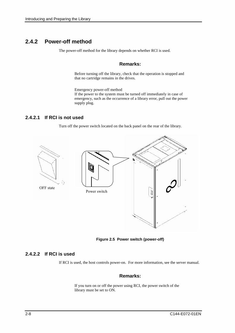
Introducing and Preparing the Library
2-8 C144-E072-01EN
2.4.2 Power-off method
The power-off method for the library depends on whether RCI is used.
Remarks:
Before turning off the library, check that the operation is stopped andthat no cartridge remains in the drives.
Emergency power-off methodIf the power to the system must be turned off immediately in case ofemergency, such as the occurrence of a library error, pull out the powersupply plug.
2.4.2.1 If RCI is not used
Turn off the power switch located on the back panel on the rear of the library.
OFF statePower switch
Figure 2.5 Power switch (power-off)
2.4.2.2 If RCI is used
If RCI is used, the host controls power-on. For more information, see the server manual.
Remarks:
If you turn on or off the power using RCI, the power switch of thelibrary must be set to ON.
2.5 Checking the Library and Drive Settings
C144-E072-01EN 2-9
2.5 Checking the Library and Drive SettingsFrom the operator panel or remote panel, check the settings of the drive and library beingused.
2.5.1 Checking the drive settings
A Fibre Channel Loop ID must be set for each drive. The factory default is "SoftAddress."
For information on the setting method, see 4.4, "Setting the Target ID of the Drive."
2.5.2 Checking the library settings
2.5.2.1 Checking the target ID setting
A Fibre Channel Loop ID must be set for each adapter port. The factory default is"Fabric."
For information on the setting method, see 4.5.1.1, "Setting the library target (Loop) IDfor each adapter."
2.5.2.2 Checking the host WWPN setting
The host WWPN for which access is permitted must be set for each adapter port. Sincethe factory default specifies no value, access from any host is permitted.
For information on the setting method, see 4.5.1.2, "Setting the host WWPN permittedfor each adapter (If needed)."
2.5.2.3 Checking the auto-cleaning function setting
The auto-cleaning function detects a cleaning request from a drive and automaticallycleans the drive using a cleaning cartridge. Auto-cleaning is enabled by the factorydefault.
For information on the setting method, see 4.5.2, "Setting library information."
2.5.2.4 Checking the auto-inventory function setting
The auto-inventory function collects cartridge information in all the cells during theinitialization operation after power-on. The factory default is that inventory is taken afterpower-on.
For information on the setting method, see 4.5.2, "Setting library information."
2.5.2.5 Checking the auto-eject function setting
The auto-eject function forcibly returns a cartridge in the drive to the original cell duringinitialization after power-on. The factory default is that a cartridge is not automaticallyreturned to the original cell.
For information on the setting method, see 4.5.2, "Setting library information."
Introducing and Preparing the Library
2-10 C144-E072-01EN
2.5.2.6 Checking the fast load function setting
The fast load function enables the next mount operation during the current mountoperation (without waiting for the drive to become ready) to speed up robot performance.The factory default is "disabled."
For information on the setting method, see 4.5.2, "Setting library information."
2.5.2.7 Checking the time and date setting
When you initially set up the library, adjust the clock in the library from the operatorpanel or remote panel.
For information on the procedure, see 4.5.4, "Setting the clock"(setting made from theoperator panel) or 5.5.4, "Setting the clock" (setting from the remote panel).
The library also supports automatic adjustment using NTP (only the client function). Forinformation on the setting method, see 4.5.3, "Setting information about the network."
2.5.2.8 Checking the remote panel settings
You can manage and monitor your own library from anywhere on the network from aneasy-to-use Web page.
To use the remote panel, you must make the network settings from the operator panel.For information on the setting method, see 4.5.3, "Setting information about thenetwork."
Remarks:
The library must be restarted for the changes to the network settingsto take effect.
2.6 Checking the Host Settings
C144-E072-01EN 2-11
2.6 Checking the Host Settings
(1) Installing the backup software and driver (if necessary)
Install the host driver, backup software, and host bus adapter card, and then make theirsettings (if they have not been set).
Remarks:
For details on the setting and check methods of the host driver andbackup software, see "ETERNUS LT160 Magnetic Tape LibraryDevice Setup Guide"
(2) Checking the installation
To check the installation, turn on the host and then search for the library and drive.
- For Windows NT, select [Settings], [Control Panel], and finally [SCSI adapter].
- For Sun Solaris, check the installation by seeing the message on the FC host busadapter driver that is output to the OS startup log (such as /var/adm/messages)specified in the /etc/syslog.conf file or using the utility commands provided with theFC host bus adapter.
Perform backup on a trial basis to make sure that all the components are correctly set up.
Remarks:
For more information on setting or checking the driver of the host busadapter or the backup software, see the "ETERNUS LT160 TapeLibrary Setup Guide" provided with the library or the host busadapter manual.

C144-E072-01EN 3-1
Chapter 3 Library Operation
3.1 Inserting and Ejecting a Cartridge (Data Cartridge)
3.2 Cleaning the Drive
3.3 Power to the unit
3.4 Turning on the server
3.1 Inserting and Ejecting a Cartridge (Data Cartridge)This section explains how to insert and eject a data cartridge.
Remarks:
For information on inserting and ejecting a cleaning cartridge, seeSection 4.9.
To insert a cartridge into a cell inside the library, either manually insert it after openingthe front door or insert it from the CAS using a backup software operation. The firstmethod allows you to insert a large number of cartridges at one time, but opening thefront door places the library offline. Therefore, if you want to insert a cartridge duringoperation, you can only do so from the CAS.
To eject a cartridge from the library, either manually eject it after opening the front dooror eject it from the CAS using a backup software operation. As with insertion of acartridge, the first method allows you to eject a large number of cartridges at one time,but opening the front door places the library offline. Therefore, if you want to eject acartridge during operation, you can only do so from the CAS (Using the operator panel,you can eject only a cleaning cartridge in the cleaning cell).
Library Operation
3-2 C144-E072-01EN
3.1.1 Inserting/Ejecting a cartridge by opening the front door
The following explains how to insert and eject a cartridge by opening the front door:
CAUTION
Damage to the library: If work is done while the front door isopen, be careful not to touch the robot, cables, and printed circuits.
1) If the front door is opened, the library goes offline. Stop the operation of backupsoftware before opening the front door.
CAUTION
Data loss: If the front door is opened during operation, the systemperforms an emergency stop. Before opening the front door, stop thesoftware backup.
2) Open the front door. At this point, make sure that a notification is displayed in thepopup window in the main area of the operator panel and the Front Door Openedicon is lit in the icon area.
3) Insert a cartridge into the cell or eject it from the cell. When inserting a cartridge,insert it as far as it will go with the cartridge having the correct orientation, as shownin Figure 3.1. If the insertion orientation is correct, the bar code label is facing thefront (orientation in which the robot can read) and the reel surface of the cartridge ispointing downward.
The hand section can be moved by hand.
When manually inserting a cartridge into the cell, insert it such that it has the correctorientation by checking the following points:
- The bar code label faces the front (orientation in which the robot can read).
- The reel surface of the cartridge faces downward.
Remarks:
Although a cartridge on which no bar code label is affixed can beused for operation, it is recommended that a cartridge on which a barcode label is affixed be used so that management information ofindividual cartridges can be differentiated.
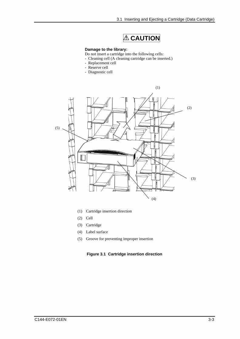
3.1 Inserting and Ejecting a Cartridge (Data Cartridge)
C144-E072-01EN 3-3
CAUTION
Damage to the library:Do not insert a cartridge into the following cells:- Cleaning cell (A cleaning cartridge can be inserted.)- Replacement cell- Reserve cell- Diagnostic cell
(1)
(2)
(3)
(4)
(5)
(1) Cartridge insertion direction
(2) Cell
(3) Cartridge
(4) Label surface
(5) Groove for preventing improper insertion
Figure 3.1 Cartridge insertion direction
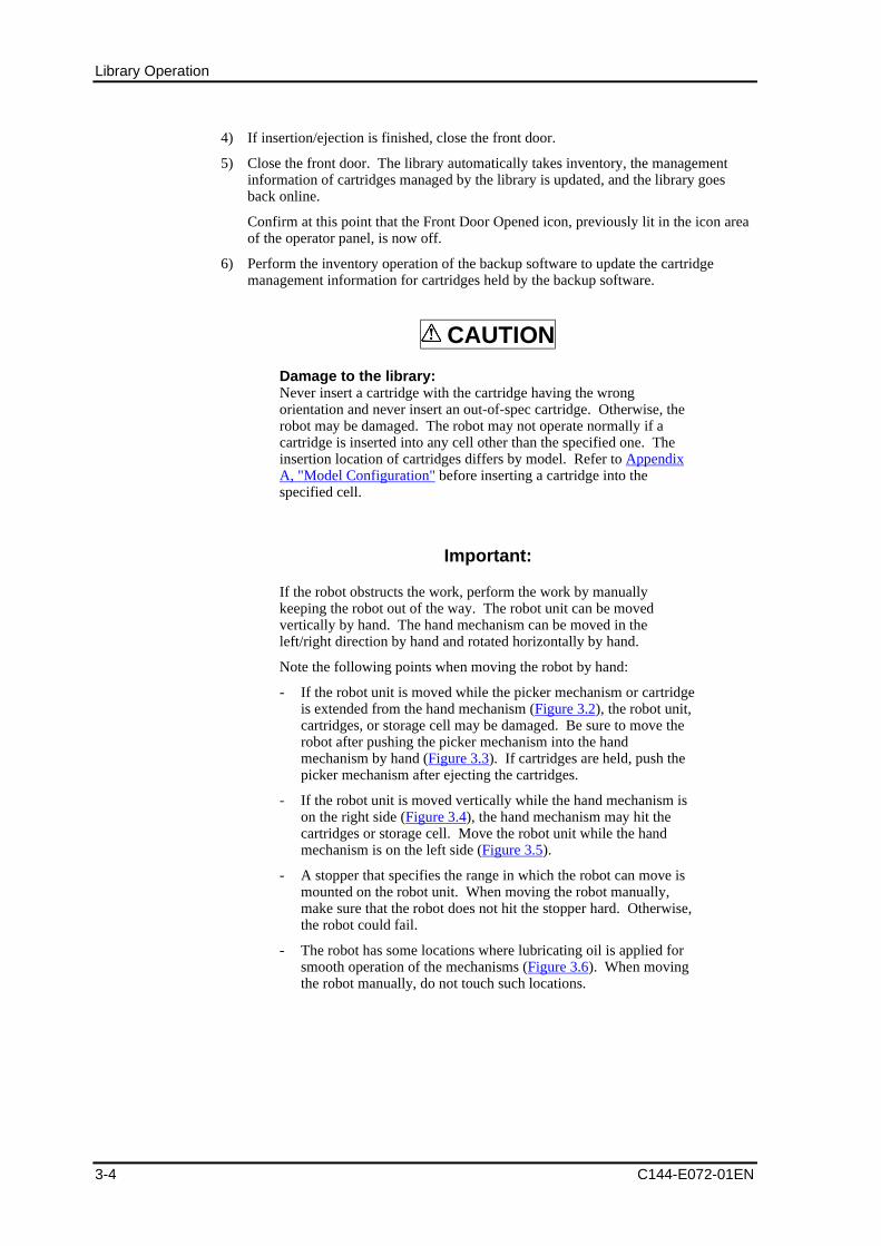
Library Operation
3-4 C144-E072-01EN
4) If insertion/ejection is finished, close the front door.
5) Close the front door. The library automatically takes inventory, the managementinformation of cartridges managed by the library is updated, and the library goesback online.
Confirm at this point that the Front Door Opened icon, previously lit in the icon areaof the operator panel, is now off.
6) Perform the inventory operation of the backup software to update the cartridgemanagement information for cartridges held by the backup software.
CAUTION
Damage to the library:Never insert a cartridge with the cartridge having the wrongorientation and never insert an out-of-spec cartridge. Otherwise, therobot may be damaged. The robot may not operate normally if acartridge is inserted into any cell other than the specified one. Theinsertion location of cartridges differs by model. Refer to AppendixA, "Model Configuration" before inserting a cartridge into thespecified cell.
Important:
If the robot obstructs the work, perform the work by manuallykeeping the robot out of the way. The robot unit can be movedvertically by hand. The hand mechanism can be moved in theleft/right direction by hand and rotated horizontally by hand.
Note the following points when moving the robot by hand:
- If the robot unit is moved while the picker mechanism or cartridgeis extended from the hand mechanism (Figure 3.2), the robot unit,cartridges, or storage cell may be damaged. Be sure to move therobot after pushing the picker mechanism into the handmechanism by hand (Figure 3.3). If cartridges are held, push thepicker mechanism after ejecting the cartridges.
- If the robot unit is moved vertically while the hand mechanism ison the right side (Figure 3.4), the hand mechanism may hit thecartridges or storage cell. Move the robot unit while the handmechanism is on the left side (Figure 3.5).
- A stopper that specifies the range in which the robot can move ismounted on the robot unit. When moving the robot manually,make sure that the robot does not hit the stopper hard. Otherwise,the robot could fail.
- The robot has some locations where lubricating oil is applied forsmooth operation of the mechanisms (Figure 3.6). When movingthe robot manually, do not touch such locations.
3.1 Inserting and Ejecting a Cartridge (Data Cartridge)
C144-E072-01EN 3-5
Hand mechanism
Picker mechanism
Figure 3.2 Picker mechanism protruding from the hand mechanism
Figure 3.3 Picker mechanism that has been completely inserted into the hand mechanism
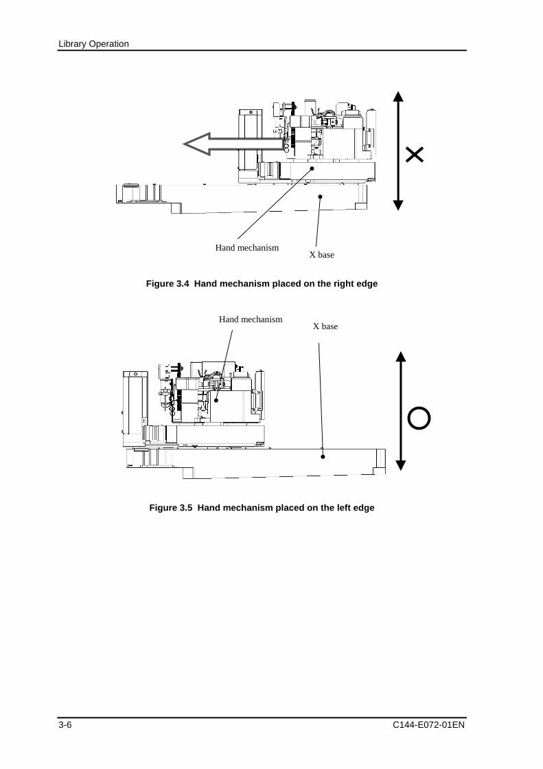
Library Operation
3-6 C144-E072-01EN
Hand mechanismX base
Figure 3.4 Hand mechanism placed on the right edge
Hand mechanismX base
Figure 3.5 Hand mechanism placed on the left edge
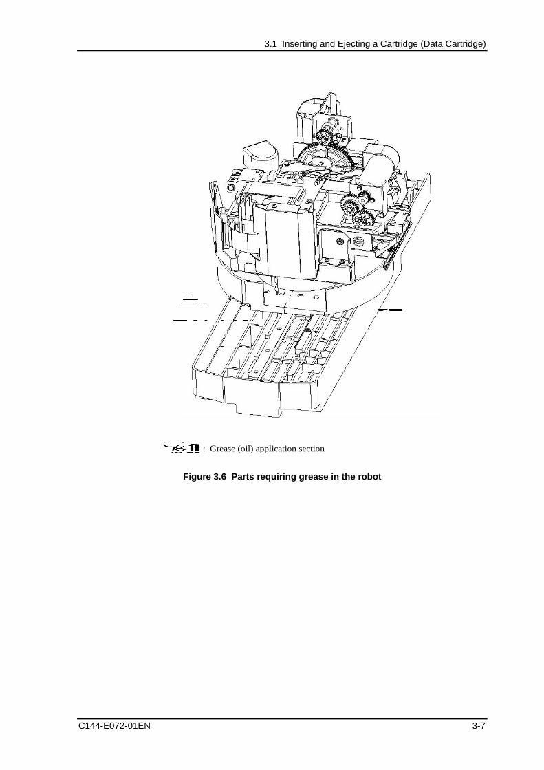
3.1 Inserting and Ejecting a Cartridge (Data Cartridge)
C144-E072-01EN 3-7
Figure 3.6 Parts requiring grease in the robot
: Grease (oil) application section
Library Operation
3-8 C144-E072-01EN
3.1.2 Inserting/Ejecting cartridges from CAS
The following explains how to insert a cartridge from CAS using the backup software.
3.1.2.1 Inserting cartridges from CAS
1) Open the magazine door. At this point, make sure that the CAS Opened icon is lit inthe icon area of the operator panel.
2) Put into the magazine the cartridge you want to insert (see 1.1.5.1, "Insertingcartridges into the magazine").
3) Close the magazine door. At this point, make sure that the CAS Opened icon is off.
4) Perform the operation for insertion into the cell using the backup software.
Remarks:
After the CAS Open icon goes out, the library automatically makes aninventory of magazines. Perform the insertion operation from thebackup software after the inventory operation is completed.
3.1.2.2 Ejecting into CAS
1) If there is no magazine in CAS, first put a magazine in CAS.
2) Perform the operation for ejection into CAS from the backup software.
3) Open the magazine door. At this point, make sure that the CAS Opened icon is lit inthe icon area of the operator panel.
Remarks:
For information about performing the CAS Open operation (to beperformed from the operator panel), see 4.6, "Opening the MagazineDoor."
4) Pull out the magazine and remove the ejected cartridge (See 1.1.5.2 "Ejectingcartridges from the magazine").
3.2 Cleaning the Drive
C144-E072-01EN 3-9
3.2 Cleaning the DriveThis section explains how to clean the drive.
The auto cleaning function and manual cleaning function are available as cleaningfunctions. Both the auto cleaning function and manual cleaning function use the cleaningcartridge in the cleaning cell.
Remarks:
1. If no cleaning cartridge is inserted into the cleaning cell, neitherthe auto cleaning function nor manual cleaning function can beused. Insert a cleaning cartridge from CAS into the cleaning cellvia operation from the operator panel.
For information about the operation using the operator panel, see4.9.1, "Inserting a cleaning cartridge."
2. The maximum number of times that a cleaning cartridge can beused is determined by each drive maker.
If the maximum number of times of a cleaning cartridge can beused in the cleaning cell is reached, the Exchange Clean Tape icongoes on in the icon area of the operator panel. If this icon is on,eject the cleaning cartridge as it should not be used any more, andreplace it with a new one.
The cleaning cartridge can be ejected into CAS by performing anoperation from the operator panel.
For information about the operation from the operator panel, see4.9.2, "Ejecting a cleaning cartridge."
Library Operation
3-10 C144-E072-01EN
3.3 Power to the unitDo not attempt to execute any operation involving software backup while the power tothe LT160 is off, or while the power is being turned on to initialize the LT160.Otherwise, a malfunction may occur.
If the power to the LT160 is turned off during backup, the integrity of data being writtencannot be guaranteed. In addition, the cartridge to which the data is being written mightbe disabled. In such a case, contact the support department in charge of the backupsoftware, take the recommended corrective action, and reexecute the backup.
3.4 Turning on the server
C144-E072-01EN 3-11
3.4 Turning on the serverIf the server is turned on while the LT160 is being initialized, the server might notcorrectly identify the LT160. Instead, turn on the server power after initialization of theLT160 is completed.

C144-E072-01EN 4-1
Chapter 4 Operator Panel Operation
4.1 Overview of the Operator Panel
4.2 Referencing the Status of the Library/Drive
4.3 Referencing Library Information
4.4 Setting the Target ID of the Drive
4.5 Setting Library Information
4.6 Opening the Magazine Door
4.7 Loading/Unloading a Cartridge
4.8 Cleaning the Drive Manually
4.9 Inserting/Ejecting a Cleaning Cartridge
4.10 Releasing a Hardware Error of the Library/Drive
4.11 Releasing the Front Door Open Status
4.12 Unloading a Cartridge Loaded from the Host
4.13 Making an Inventory
4.1 Overview of the Operator Panel
4.1.1 Touch-panel operation
The operator panel is positioned on the front of the library.
It is possible to perform operations such as referencing/setting the library and drive statusand opening the magazine door of CAS from the operator panel.
By selecting the buttons on the operator panel, operations such as window transition,function selection, and setup value input can be performed.
The menu structure of the operator panel is as shown below:
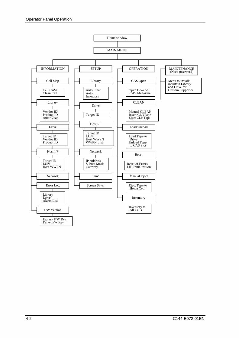
Operator Panel Operation
4-2 C144-E072-01EN
Home window
INFORMATION
Cell Map
Cell/CAS/Clean Cell
Library
Drive
Host I/F
Network
Error Log
F/W Version
LibraryDriveAlarm List
SETUP MAINTENANCE(Need password)
Library F/W RevDrive F/W Rev
Library
Auto CleanAutoInventory
d
Drive
Target ID
Target IDLUNHost WWPN
Host I/F
Target IDLUNHost WWPNWWPN List
Network
IP AddressSubnet MaskGateway
CLEAN
Manual CLEANInsert CLNTapeEject CLNTape
CAS Open
Load/Unload
Reset
Manual Eject
Load Tape to DriveUnload Tape to CAS Slot
Open Door of CAS Magazine
Eject Tape to Home Cell
Reset of ErrorsLIB Initialization
Menu to install/maintain Libraryand Drive forCustom Supporter
Vendor IDProduct IDAuto Clean
Target IDVendor IDProduct ID
Time
Screen Saver
Inventory
Inventory to All Cells
MAIN MENU
OPERATION
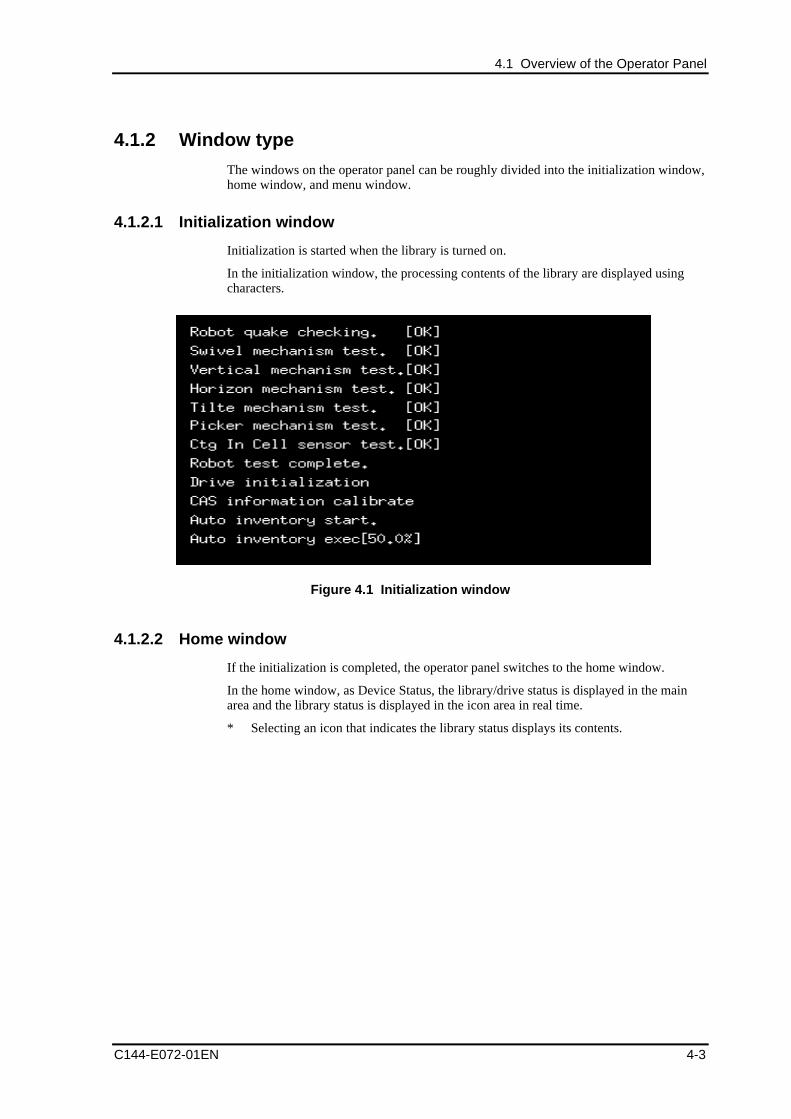
4.1 Overview of the Operator Panel
C144-E072-01EN 4-3
4.1.2 Window type
The windows on the operator panel can be roughly divided into the initialization window,home window, and menu window.
4.1.2.1 Initialization window
Initialization is started when the library is turned on.
In the initialization window, the processing contents of the library are displayed usingcharacters.
Figure 4.1 Initialization window
4.1.2.2 Home window
If the initialization is completed, the operator panel switches to the home window.
In the home window, as Device Status, the library/drive status is displayed in the mainarea and the library status is displayed in the icon area in real time.
* Selecting an icon that indicates the library status displays its contents.
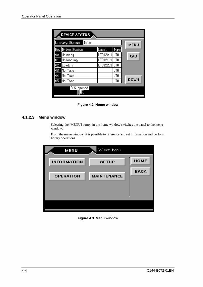
Operator Panel Operation
4-4 C144-E072-01EN
Figure 4.2 Home window
4.1.2.3 Menu window
Selecting the [MENU] button in the home window switches the panel to the menuwindow.
From the menu window, it is possible to reference and set information and performlibrary operations.
Figure 4.3 Menu window
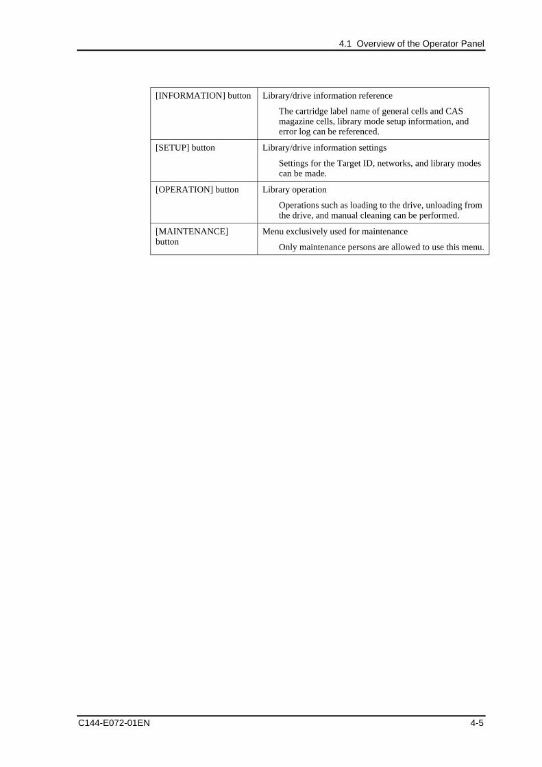
4.1 Overview of the Operator Panel
C144-E072-01EN 4-5
[INFORMATION] button Library/drive information reference
The cartridge label name of general cells and CASmagazine cells, library mode setup information, anderror log can be referenced.
[SETUP] button Library/drive information settings
Settings for the Target ID, networks, and library modescan be made.
[OPERATION] button Library operation
Operations such as loading to the drive, unloading fromthe drive, and manual cleaning can be performed.
[MAINTENANCE]button
Menu exclusively used for maintenance
Only maintenance persons are allowed to use this menu.
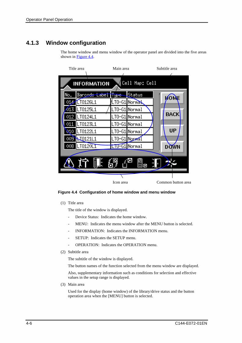
Operator Panel Operation
4-6 C144-E072-01EN
4.1.3 Window configuration
The home window and menu window of the operator panel are divided into the five areasshown in Figure 4.4.
Figure 4.4 Configuration of home window and menu window
(1) Title area
The title of the window is displayed.
- Device Status: Indicates the home window.
- MENU: Indicates the menu window after the MENU button is selected.
- INFORMATION: Indicates the INFORMATION menu.
- SETUP: Indicates the SETUP menu.
- OPERATION: Indicates the OPERATION menu.
(2) Subtitle area
The subtitle of the window is displayed.
The button names of the function selected from the menu window are displayed.
Also, supplementary information such as conditions for selection and effectivevalues in the setup range is displayed.
(3) Main area
Used for the display (home window) of the library/drive status and the buttonoperation area when the [MENU] button is selected.
Icon area
Main area Subtitle areaTitle area
Common button area
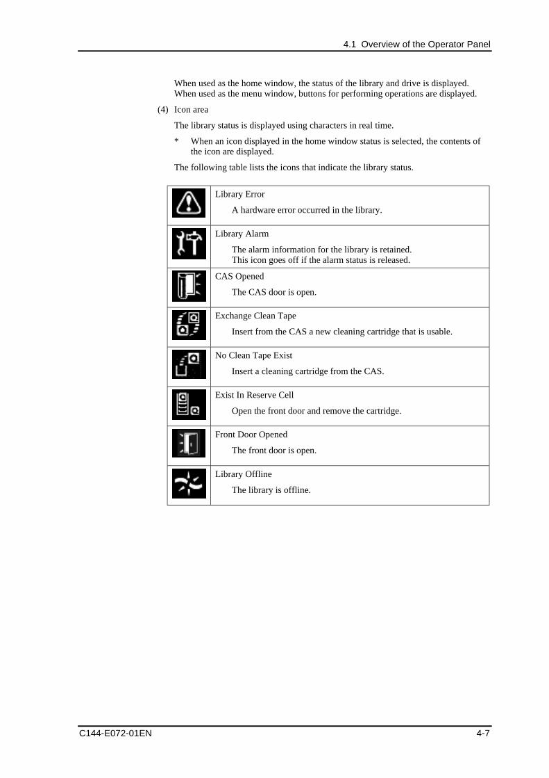
4.1 Overview of the Operator Panel
C144-E072-01EN 4-7
When used as the home window, the status of the library and drive is displayed.When used as the menu window, buttons for performing operations are displayed.
(4) Icon area
The library status is displayed using characters in real time.
* When an icon displayed in the home window status is selected, the contents ofthe icon are displayed.
The following table lists the icons that indicate the library status.
Library Error
A hardware error occurred in the library.
Library Alarm
The alarm information for the library is retained.This icon goes off if the alarm status is released.
CAS Opened
The CAS door is open.
Exchange Clean Tape
Insert from the CAS a new cleaning cartridge that is usable.
No Clean Tape Exist
Insert a cleaning cartridge from the CAS.
Exist In Reserve Cell
Open the front door and remove the cartridge.
Front Door Opened
The front door is open.
Library Offline
The library is offline.
Operator Panel Operation
4-8 C144-E072-01EN
(5) Common button area
Common button operation area to the windows displayed in the main area
- [MENU] button
Switches the main area from the home window to the menu window.
- [HOME] button
Returns to the home window from the menu window.
- [UP] button
Scrolls back to the previous page in the home and menu windows.
- [DOWN] button
Scrolls to the next page in the home and menu windows.
- [BACK] button
Returns to the previous window in the menu window.
- [CAS] button
Shortcut to the menu to open the magazine door of CAS
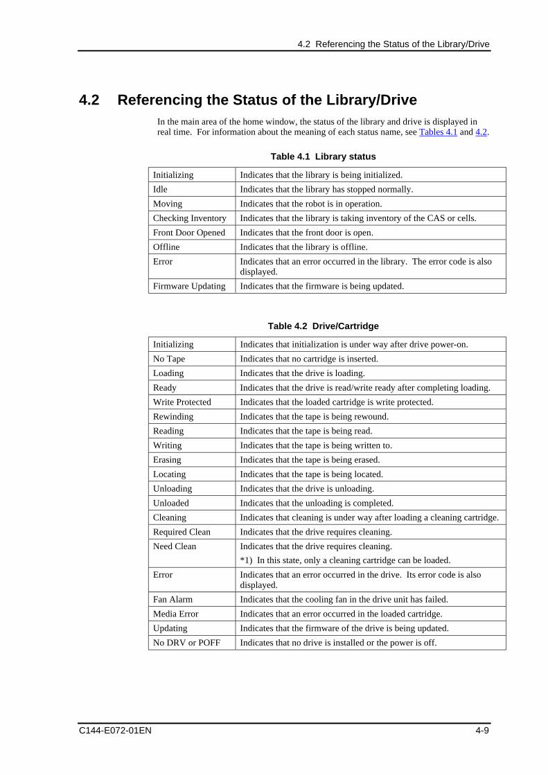
4.2 Referencing the Status of the Library/Drive
C144-E072-01EN 4-9
4.2 Referencing the Status of the Library/DriveIn the main area of the home window, the status of the library and drive is displayed inreal time. For information about the meaning of each status name, see Tables 4.1 and 4.2.
Table 4.1 Library status
Initializing Indicates that the library is being initialized.
Idle Indicates that the library has stopped normally.
Moving Indicates that the robot is in operation.
Checking Inventory Indicates that the library is taking inventory of the CAS or cells.
Front Door Opened Indicates that the front door is open.
Offline Indicates that the library is offline.
Error Indicates that an error occurred in the library. The error code is alsodisplayed.
Firmware Updating Indicates that the firmware is being updated.
Table 4.2 Drive/Cartridge
Initializing Indicates that initialization is under way after drive power-on.
No Tape Indicates that no cartridge is inserted.
Loading Indicates that the drive is loading.
Ready Indicates that the drive is read/write ready after completing loading.
Write Protected Indicates that the loaded cartridge is write protected.
Rewinding Indicates that the tape is being rewound.
Reading Indicates that the tape is being read.
Writing Indicates that the tape is being written to.
Erasing Indicates that the tape is being erased.
Locating Indicates that the tape is being located.
Unloading Indicates that the drive is unloading.
Unloaded Indicates that the unloading is completed.
Cleaning Indicates that cleaning is under way after loading a cleaning cartridge.
Required Clean Indicates that the drive requires cleaning.
Need Clean Indicates that the drive requires cleaning.
*1) In this state, only a cleaning cartridge can be loaded.
Error Indicates that an error occurred in the drive. Its error code is alsodisplayed.
Fan Alarm Indicates that the cooling fan in the drive unit has failed.
Media Error Indicates that an error occurred in the loaded cartridge.
Updating Indicates that the firmware of the drive is being updated.
No DRV or POFF Indicates that no drive is installed or the power is off.
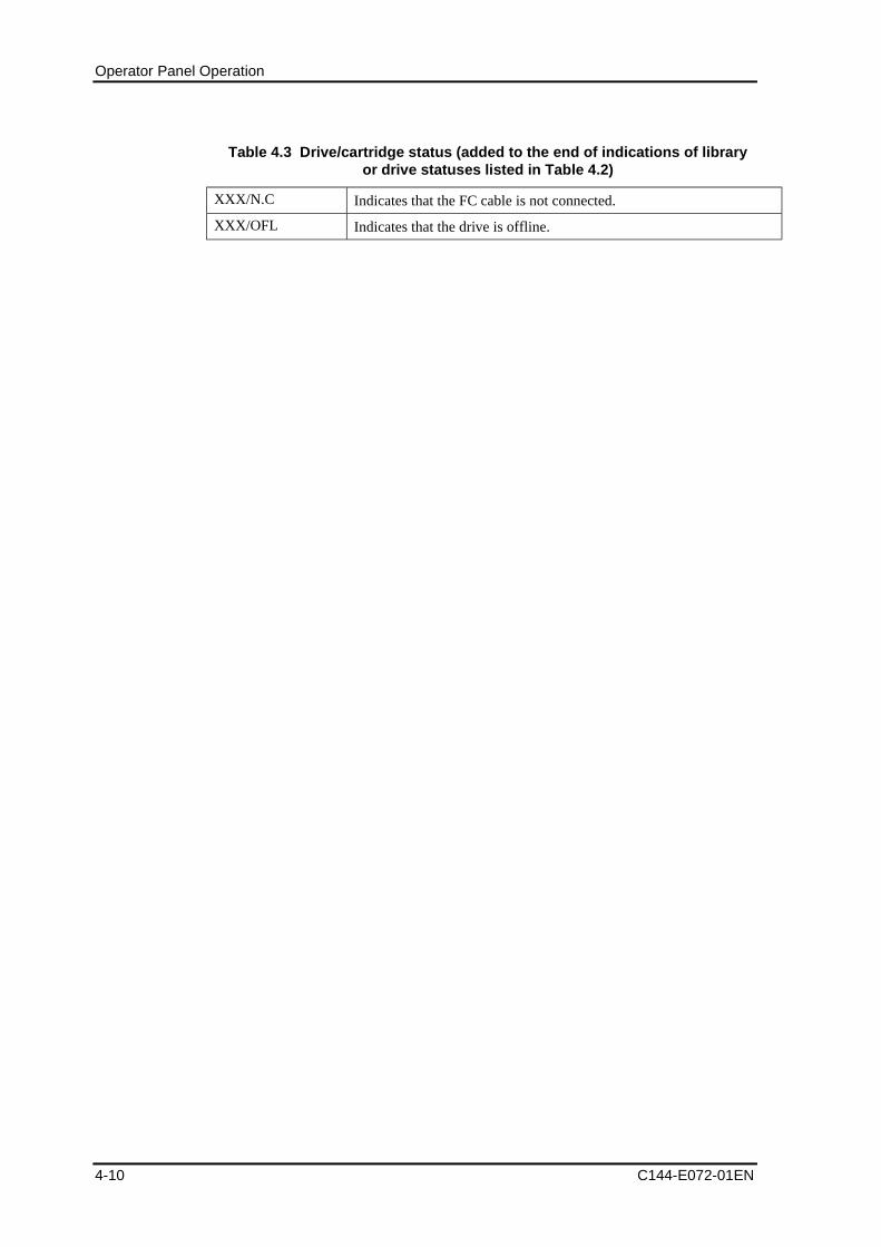
Operator Panel Operation
4-10 C144-E072-01EN
Table 4.3 Drive/cartridge status (added to the end of indications of libraryor drive statuses listed in Table 4.2)
XXX/N.C Indicates that the FC cable is not connected.
XXX/OFL Indicates that the drive is offline.
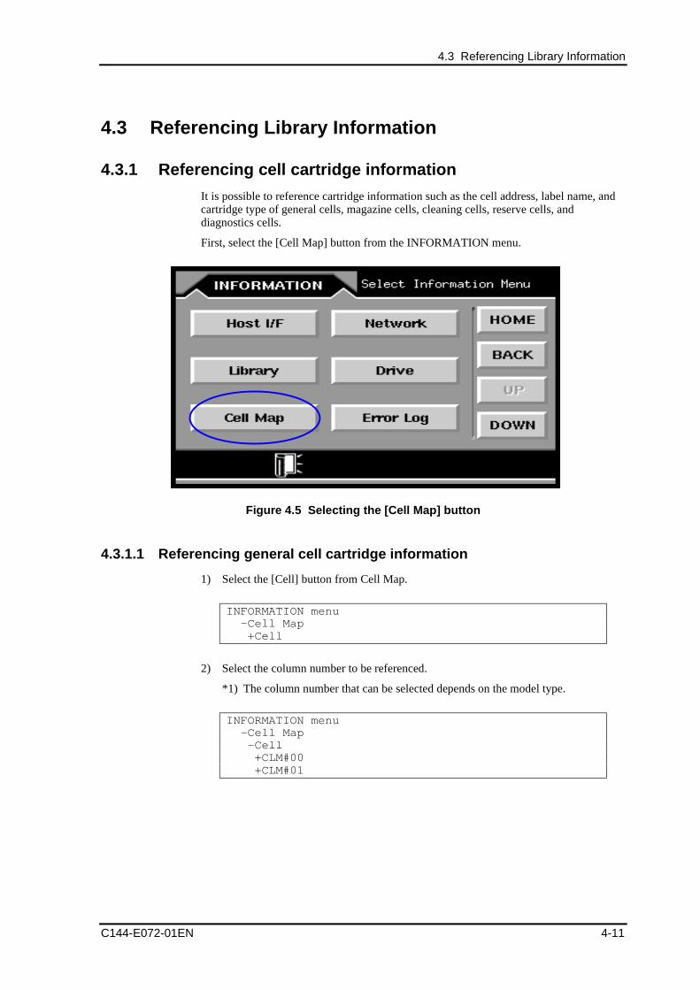
4.3 Referencing Library Information
C144-E072-01EN 4-11
4.3 Referencing Library Information
4.3.1 Referencing cell cartridge information
It is possible to reference cartridge information such as the cell address, label name, andcartridge type of general cells, magazine cells, cleaning cells, reserve cells, anddiagnostics cells.
First, select the [Cell Map] button from the INFORMATION menu.
Figure 4.5 Selecting the [Cell Map] button
4.3.1.1 Referencing general cell cartridge information
1) Select the [Cell] button from Cell Map.
INFORMATION menu -Cell Map +Cell
2) Select the column number to be referenced.
*1) The column number that can be selected depends on the model type.
INFORMATION menu -Cell Map -Cell +CLM#00 +CLM#01
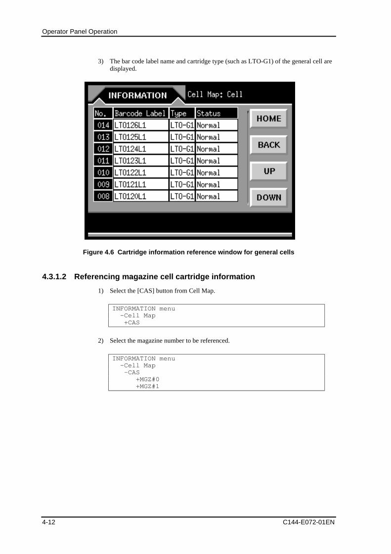
Operator Panel Operation
4-12 C144-E072-01EN
3) The bar code label name and cartridge type (such as LTO-G1) of the general cell aredisplayed.
Figure 4.6 Cartridge information reference window for general cells
4.3.1.2 Referencing magazine cell cartridge information
1) Select the [CAS] button from Cell Map.
INFORMATION menu -Cell Map +CAS
2) Select the magazine number to be referenced.
INFORMATION menu -Cell Map -CAS +MGZ#0 +MGZ#1
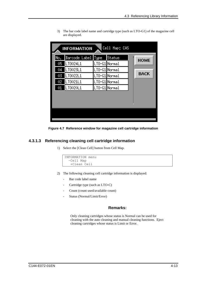
4.3 Referencing Library Information
C144-E072-01EN 4-13
3) The bar code label name and cartridge type (such as LTO-G1) of the magazine cellare displayed.
Figure 4.7 Reference window for magazine cell cartridge information
4.3.1.3 Referencing cleaning cell cartridge information
1) Select the [Clean Cell] button from Cell Map.
INFORMATION menu -Cell Map +Clean Cell
2) The following cleaning cell cartridge information is displayed:
- Bar code label name
- Cartridge type (such as LTO-C)
- Count (count used/available count)
- Status (Normal/Limit/Error)
Remarks:
Only cleaning cartridges whose status is Normal can be used forcleaning with the auto cleaning and manual cleaning functions. Ejectcleaning cartridges whose status is Limit or Error.
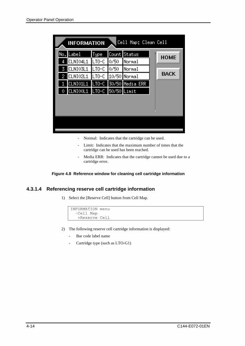
Operator Panel Operation
4-14 C144-E072-01EN
- Normal: Indicates that the cartridge can be used.
- Limit: Indicates that the maximum number of times that thecartridge can be used has been reached.
- Media ERR: Indicates that the cartridge cannot be used due to acartridge error.
Figure 4.8 Reference window for cleaning cell cartridge information
4.3.1.4 Referencing reserve cell cartridge information
1) Select the [Reserve Cell] button from Cell Map.
INFORMATION menu -Cell Map +Reserve Cell
2) The following reserve cell cartridge information is displayed:
- Bar code label name
- Cartridge type (such as LTO-G1)
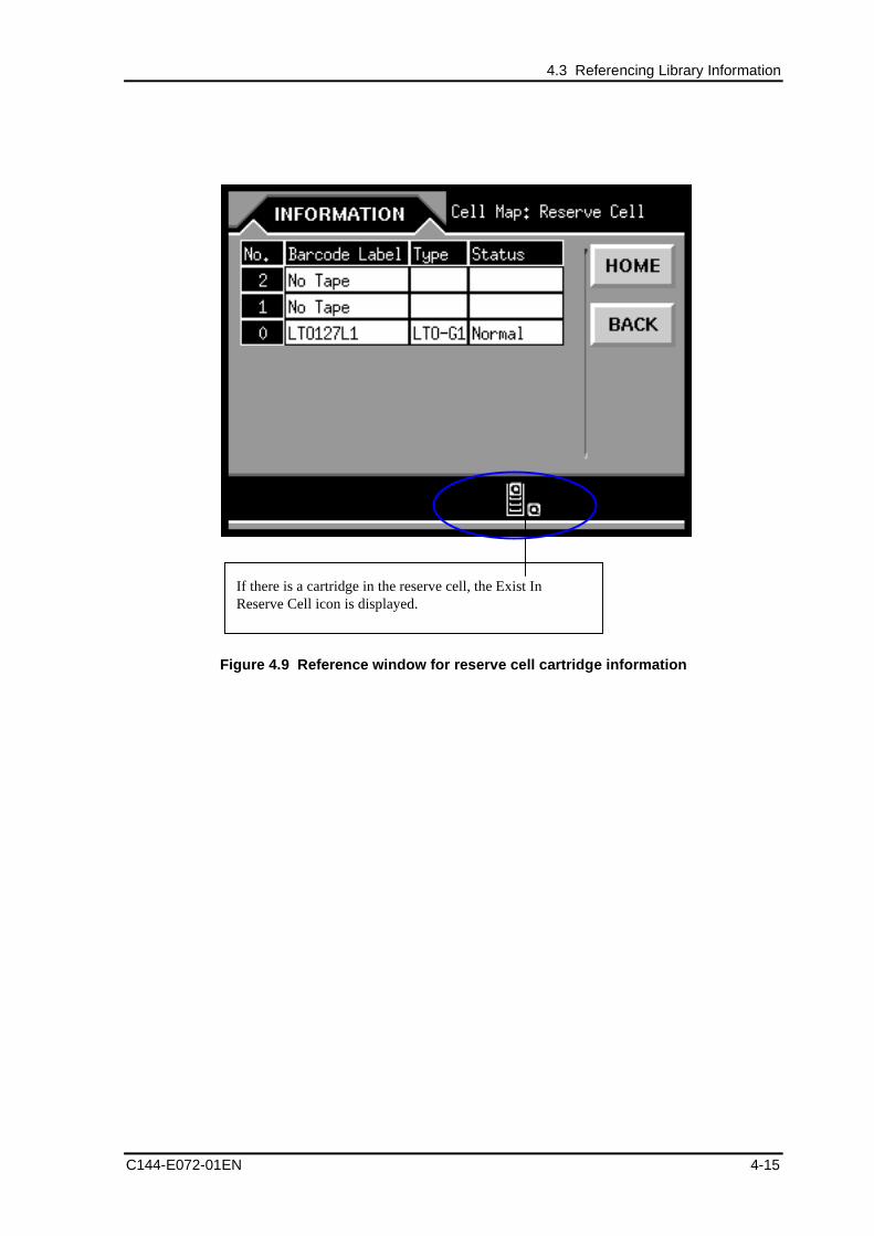
4.3 Referencing Library Information
C144-E072-01EN 4-15
Figure 4.9 Reference window for reserve cell cartridge information
If there is a cartridge in the reserve cell, the Exist InReserve Cell icon is displayed.
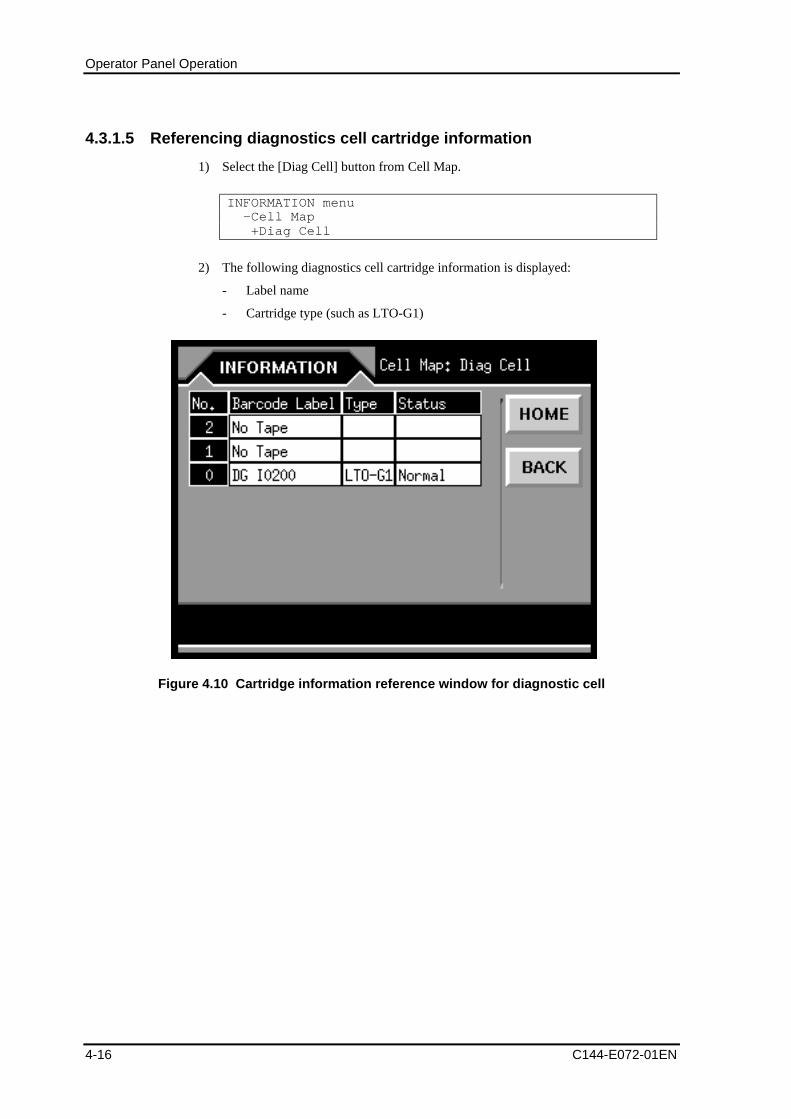
Operator Panel Operation
4-16 C144-E072-01EN
4.3.1.5 Referencing diagnostics cell cartridge information
1) Select the [Diag Cell] button from Cell Map.
INFORMATION menu -Cell Map +Diag Cell
2) The following diagnostics cell cartridge information is displayed:
- Label name
- Cartridge type (such as LTO-G1)
Figure 4.10 Cartridge information reference window for diagnostic cell
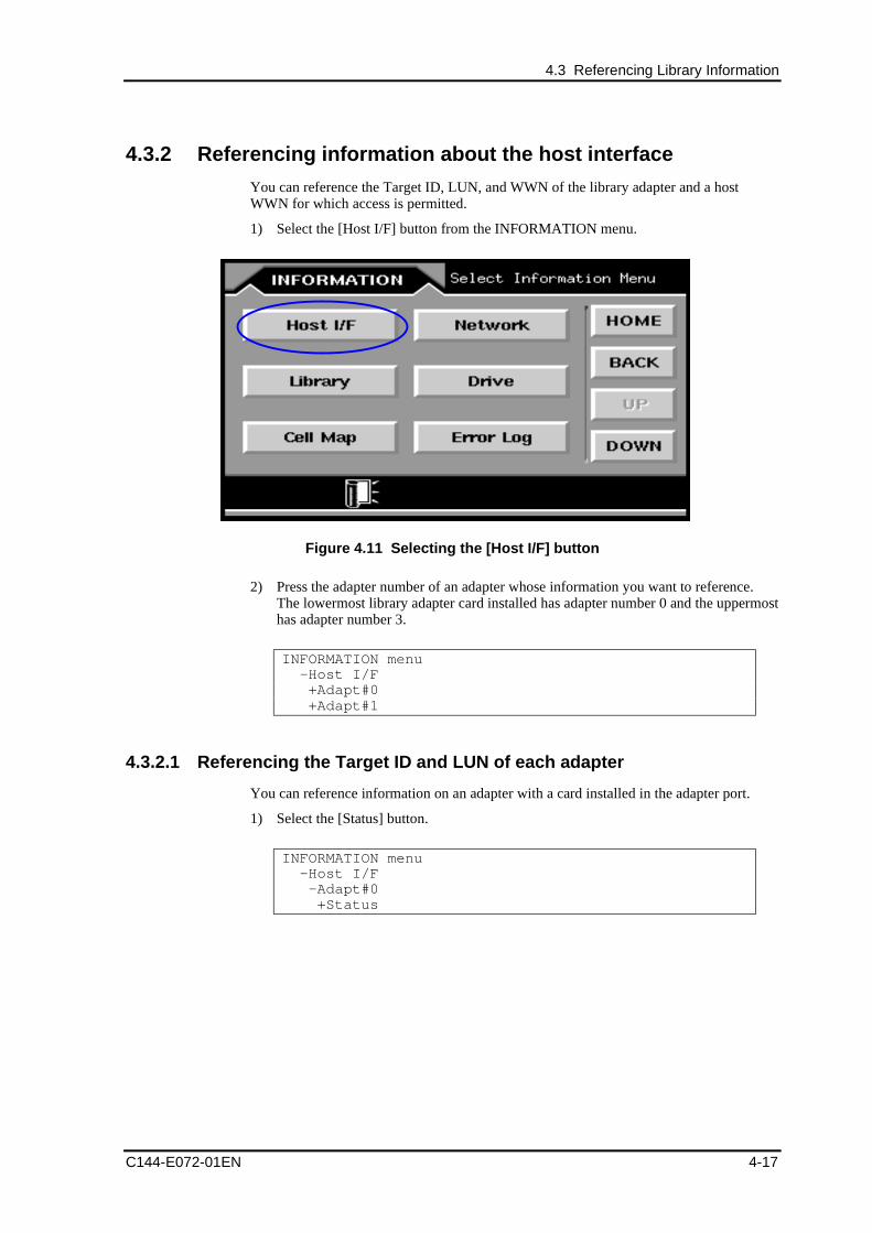
4.3 Referencing Library Information
C144-E072-01EN 4-17
4.3.2 Referencing information about the host interface
You can reference the Target ID, LUN, and WWN of the library adapter and a hostWWN for which access is permitted.
1) Select the [Host I/F] button from the INFORMATION menu.
Figure 4.11 Selecting the [Host I/F] button
2) Press the adapter number of an adapter whose information you want to reference.The lowermost library adapter card installed has adapter number 0 and the uppermosthas adapter number 3.
INFORMATION menu -Host I/F +Adapt#0 +Adapt#1
4.3.2.1 Referencing the Target ID and LUN of each adapter
You can reference information on an adapter with a card installed in the adapter port.
1) Select the [Status] button.
INFORMATION menu -Host I/F -Adapt#0 +Status
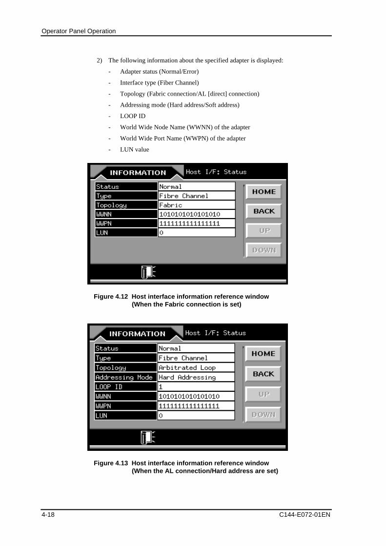
Operator Panel Operation
4-18 C144-E072-01EN
2) The following information about the specified adapter is displayed:
- Adapter status (Normal/Error)
- Interface type (Fiber Channel)
- Topology (Fabric connection/AL [direct] connection)
- Addressing mode (Hard address/Soft address)
- LOOP ID
- World Wide Node Name (WWNN) of the adapter
- World Wide Port Name (WWPN) of the adapter
- LUN value
Figure 4.12 Host interface information reference window(When the Fabric connection is set)
Figure 4.13 Host interface information reference window(When the AL connection/Hard address are set)
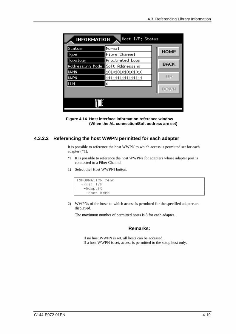
4.3 Referencing Library Information
C144-E072-01EN 4-19
Figure 4.14 Host interface information reference window(When the AL connection/Soft address are set)
4.3.2.2 Referencing the host WWPN permitted for each adapter
It is possible to reference the host WWPN to which access is permitted set for eachadapter (*1).
*1 It is possible to reference the host WWPNs for adapters whose adapter port isconnected to a Fiber Channel.
1) Select the [Host WWPN] button.
INFORMATION menu -Host I/F -Adapt#0 +Host WWPN
2) WWPNs of the hosts to which access is permitted for the specified adapter aredisplayed.
The maximum number of permitted hosts is 8 for each adapter.
Remarks:
If no host WWPN is set, all hosts can be accessed.If a host WWPN is set, access is permitted to the setup host only.
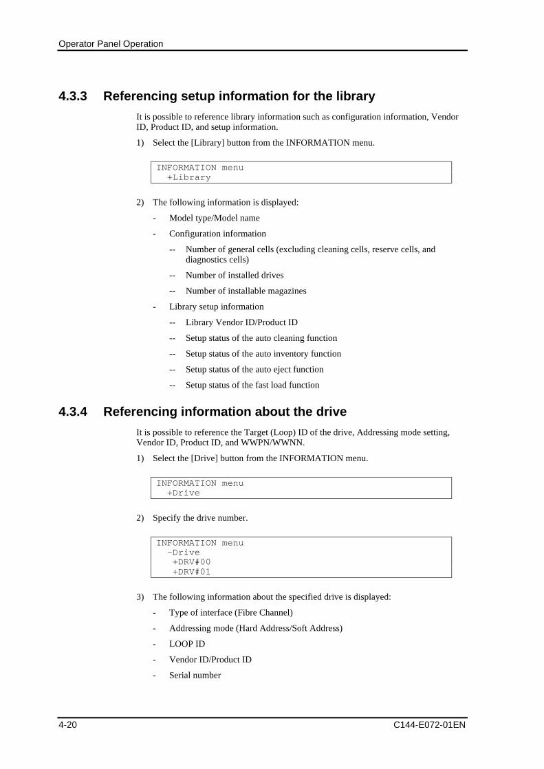
Operator Panel Operation
4-20 C144-E072-01EN
4.3.3 Referencing setup information for the library
It is possible to reference library information such as configuration information, VendorID, Product ID, and setup information.
1) Select the [Library] button from the INFORMATION menu.
INFORMATION menu +Library
2) The following information is displayed:
- Model type/Model name
- Configuration information
-- Number of general cells (excluding cleaning cells, reserve cells, anddiagnostics cells)
-- Number of installed drives
-- Number of installable magazines
- Library setup information
-- Library Vendor ID/Product ID
-- Setup status of the auto cleaning function
-- Setup status of the auto inventory function
-- Setup status of the auto eject function
-- Setup status of the fast load function
4.3.4 Referencing information about the drive
It is possible to reference the Target (Loop) ID of the drive, Addressing mode setting,Vendor ID, Product ID, and WWPN/WWNN.
1) Select the [Drive] button from the INFORMATION menu.
INFORMATION menu +Drive
2) Specify the drive number.
INFORMATION menu -Drive +DRV#00 +DRV#01
3) The following information about the specified drive is displayed:
- Type of interface (Fibre Channel)
- Addressing mode (Hard Address/Soft Address)
- LOOP ID
- Vendor ID/Product ID
- Serial number
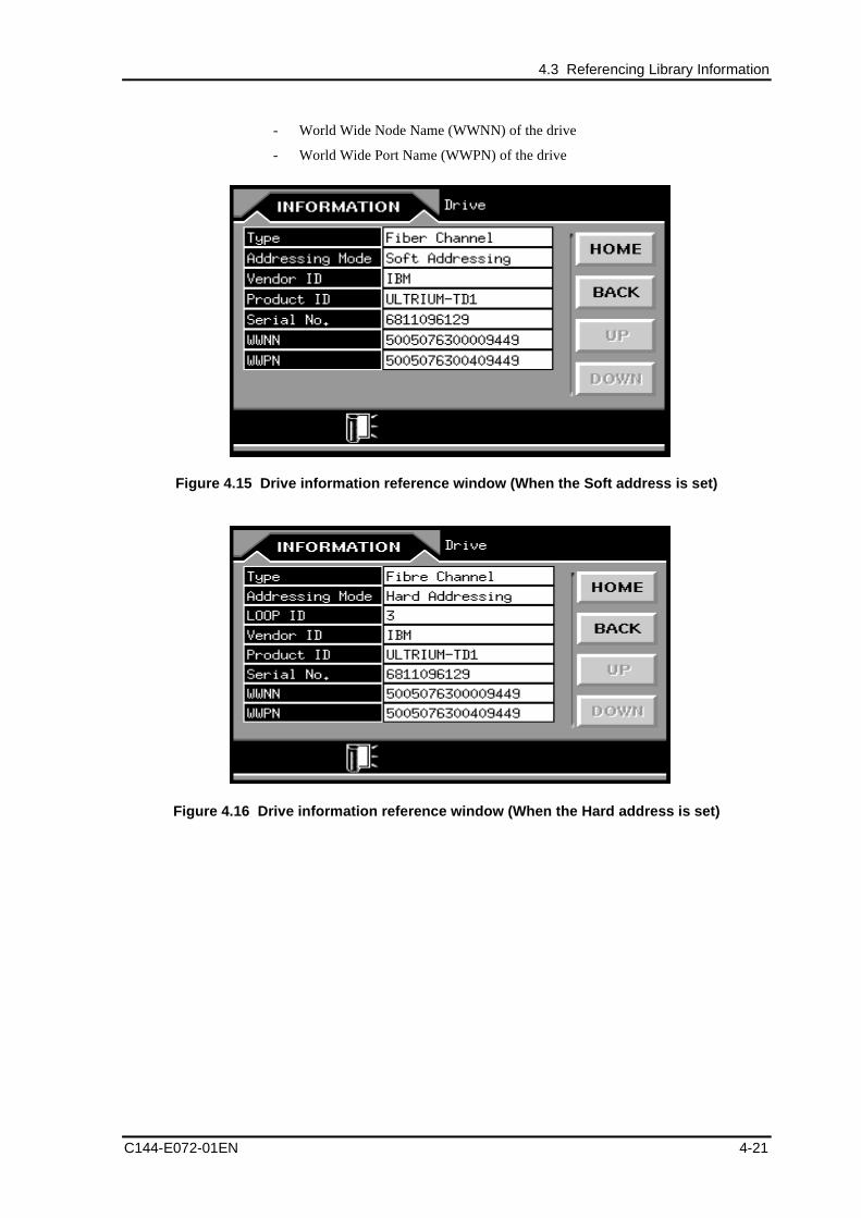
4.3 Referencing Library Information
C144-E072-01EN 4-21
- World Wide Node Name (WWNN) of the drive
- World Wide Port Name (WWPN) of the drive
Figure 4.15 Drive information reference window (When the Soft address is set)
Figure 4.16 Drive information reference window (When the Hard address is set)
Operator Panel Operation
4-22 C144-E072-01EN
4.3.5 Referencing setup information for the network
It is possible to reference setup information for the IP address, subnet mask, gateway, andMAC address.
1) Select the [Network] button from the INFORMATION menu.
INFORMATION menu +Network
2) The following setup address information about the network is displayed:
- IP address
- Subnet mask
- Gateway
- MAC address
4.3.6 Referencing error information
It is possible to reference information about hardware errors that occurred and alarmerrors that have not been released.
Remarks:
If a hardware error occurs, the Library Error icon is displayed in thehome window. If an alarm error occurs, the Library Alarm icon isdisplayed in the home window.
First, select the [Error Log] button from the INFORMATION menu.
INFORMATION menu +Error Log
4.3.6.1 Referencing hardware error information for the library
To reference error information (such as the date/time of occurrence and error code) of thelibrary, select the [Library Log] button.
INFORMATION menu -Error Log +Library Log
Ten pieces of error information in the past can be referenced.
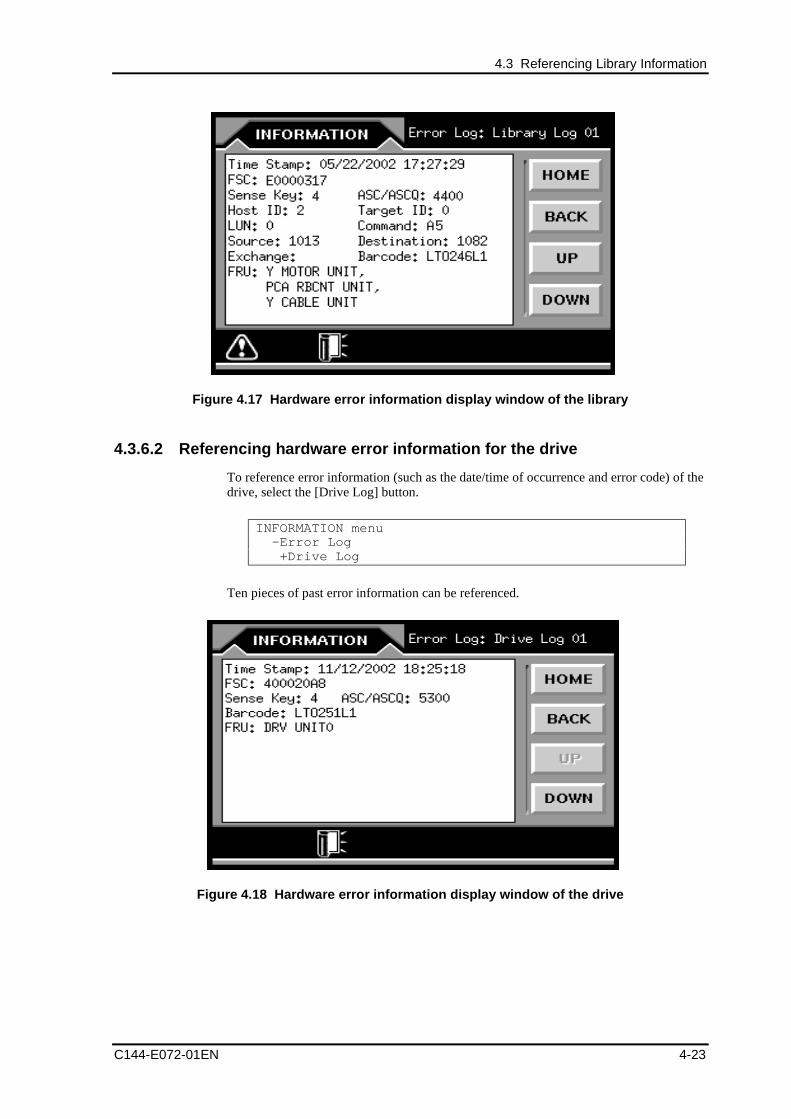
4.3 Referencing Library Information
C144-E072-01EN 4-23
Figure 4.17 Hardware error information display window of the library
4.3.6.2 Referencing hardware error information for the drive
To reference error information (such as the date/time of occurrence and error code) of thedrive, select the [Drive Log] button.
INFORMATION menu -Error Log +Drive Log
Ten pieces of past error information can be referenced.
Figure 4.18 Hardware error information display window of the drive
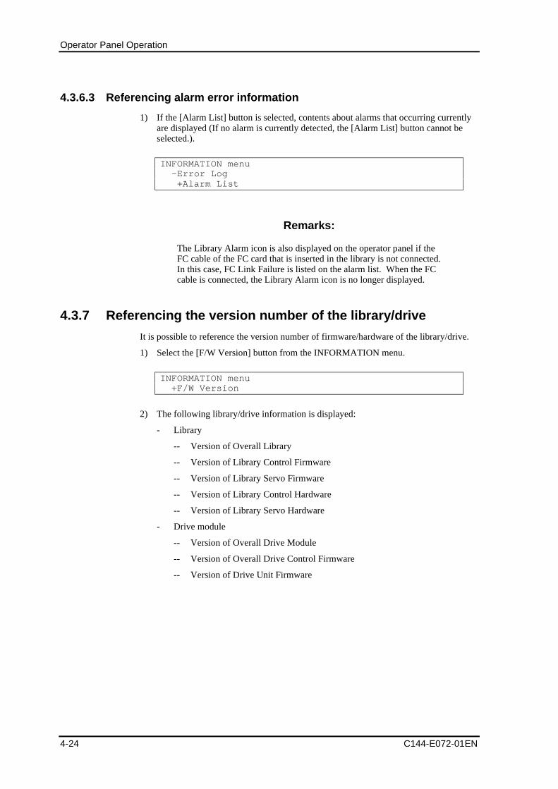
Operator Panel Operation
4-24 C144-E072-01EN
4.3.6.3 Referencing alarm error information
1) If the [Alarm List] button is selected, contents about alarms that occurring currentlyare displayed (If no alarm is currently detected, the [Alarm List] button cannot beselected.).
INFORMATION menu -Error Log +Alarm List
Remarks:
The Library Alarm icon is also displayed on the operator panel if theFC cable of the FC card that is inserted in the library is not connected.In this case, FC Link Failure is listed on the alarm list. When the FCcable is connected, the Library Alarm icon is no longer displayed.
4.3.7 Referencing the version number of the library/drive
It is possible to reference the version number of firmware/hardware of the library/drive.
1) Select the [F/W Version] button from the INFORMATION menu.
INFORMATION menu +F/W Version
2) The following library/drive information is displayed:
- Library
-- Version of Overall Library
-- Version of Library Control Firmware
-- Version of Library Servo Firmware
-- Version of Library Control Hardware
-- Version of Library Servo Hardware
- Drive module
-- Version of Overall Drive Module
-- Version of Overall Drive Control Firmware
-- Version of Drive Unit Firmware
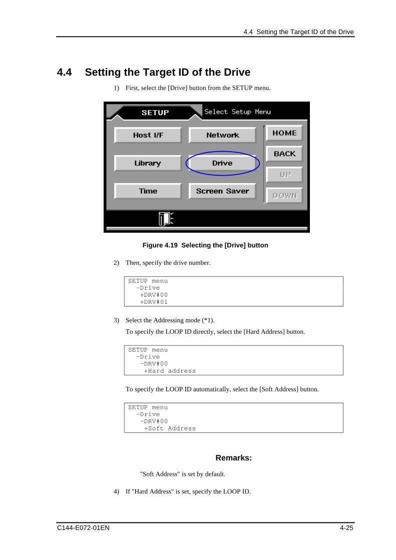
4.4 Setting the Target ID of the Drive
C144-E072-01EN 4-25
4.4 Setting the Target ID of the Drive1) First, select the [Drive] button from the SETUP menu.
Figure 4.19 Selecting the [Drive] button
2) Then, specify the drive number.
SETUP menu -Drive +DRV#00 +DRV#01
3) Select the Addressing mode (*1).
To specify the LOOP ID directly, select the [Hard Address] button.
SETUP menu -Drive -DRV#00 +Hard address
To specify the LOOP ID automatically, select the [Soft Address] button.
SETUP menu -Drive -DRV#00 +Soft Address
Remarks:
"Soft Address" is set by default.
4) If "Hard Address" is set, specify the LOOP ID.
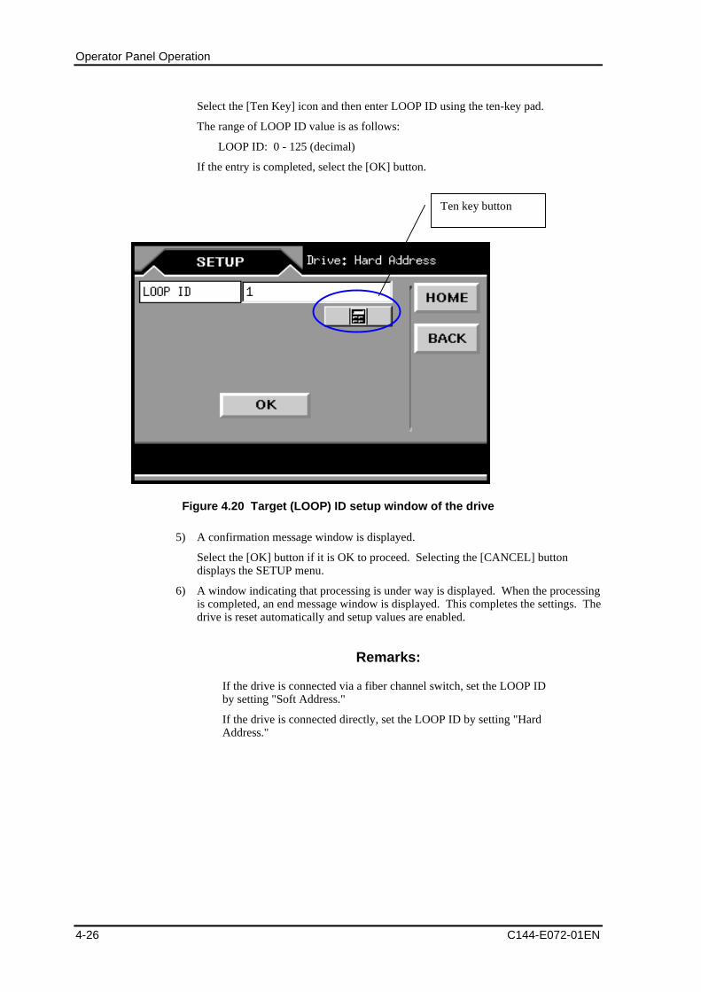
Operator Panel Operation
4-26 C144-E072-01EN
Select the [Ten Key] icon and then enter LOOP ID using the ten-key pad.
The range of LOOP ID value is as follows:
LOOP ID: 0 - 125 (decimal)
If the entry is completed, select the [OK] button.
Ten key button
Figure 4.20 Target (LOOP) ID setup window of the drive
5) A confirmation message window is displayed.
Select the [OK] button if it is OK to proceed. Selecting the [CANCEL] buttondisplays the SETUP menu.
6) A window indicating that processing is under way is displayed. When the processingis completed, an end message window is displayed. This completes the settings. Thedrive is reset automatically and setup values are enabled.
Remarks:
If the drive is connected via a fiber channel switch, set the LOOP IDby setting "Soft Address."
If the drive is connected directly, set the LOOP ID by setting "HardAddress."
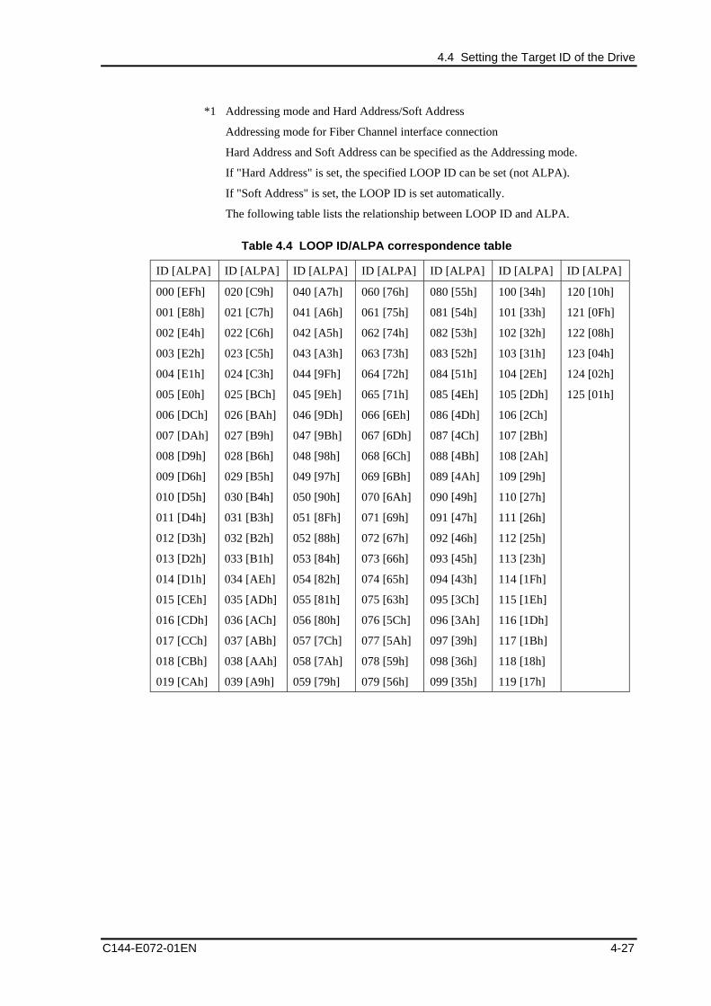
4.4 Setting the Target ID of the Drive
C144-E072-01EN 4-27
*1 Addressing mode and Hard Address/Soft Address
Addressing mode for Fiber Channel interface connection
Hard Address and Soft Address can be specified as the Addressing mode.
If "Hard Address" is set, the specified LOOP ID can be set (not ALPA).
If "Soft Address" is set, the LOOP ID is set automatically.
The following table lists the relationship between LOOP ID and ALPA.
Table 4.4 LOOP ID/ALPA correspondence table
ID [ALPA] ID [ALPA] ID [ALPA] ID [ALPA] ID [ALPA] ID [ALPA] ID [ALPA]
000 [EFh]
001 [E8h]
002 [E4h]
003 [E2h]
004 [E1h]
005 [E0h]
006 [DCh]
007 [DAh]
008 [D9h]
009 [D6h]
010 [D5h]
011 [D4h]
012 [D3h]
013 [D2h]
014 [D1h]
015 [CEh]
016 [CDh]
017 [CCh]
018 [CBh]
019 [CAh]
020 [C9h]
021 [C7h]
022 [C6h]
023 [C5h]
024 [C3h]
025 [BCh]
026 [BAh]
027 [B9h]
028 [B6h]
029 [B5h]
030 [B4h]
031 [B3h]
032 [B2h]
033 [B1h]
034 [AEh]
035 [ADh]
036 [ACh]
037 [ABh]
038 [AAh]
039 [A9h]
040 [A7h]
041 [A6h]
042 [A5h]
043 [A3h]
044 [9Fh]
045 [9Eh]
046 [9Dh]
047 [9Bh]
048 [98h]
049 [97h]
050 [90h]
051 [8Fh]
052 [88h]
053 [84h]
054 [82h]
055 [81h]
056 [80h]
057 [7Ch]
058 [7Ah]
059 [79h]
060 [76h]
061 [75h]
062 [74h]
063 [73h]
064 [72h]
065 [71h]
066 [6Eh]
067 [6Dh]
068 [6Ch]
069 [6Bh]
070 [6Ah]
071 [69h]
072 [67h]
073 [66h]
074 [65h]
075 [63h]
076 [5Ch]
077 [5Ah]
078 [59h]
079 [56h]
080 [55h]
081 [54h]
082 [53h]
083 [52h]
084 [51h]
085 [4Eh]
086 [4Dh]
087 [4Ch]
088 [4Bh]
089 [4Ah]
090 [49h]
091 [47h]
092 [46h]
093 [45h]
094 [43h]
095 [3Ch]
096 [3Ah]
097 [39h]
098 [36h]
099 [35h]
100 [34h]
101 [33h]
102 [32h]
103 [31h]
104 [2Eh]
105 [2Dh]
106 [2Ch]
107 [2Bh]
108 [2Ah]
109 [29h]
110 [27h]
111 [26h]
112 [25h]
113 [23h]
114 [1Fh]
115 [1Eh]
116 [1Dh]
117 [1Bh]
118 [18h]
119 [17h]
120 [10h]
121 [0Fh]
122 [08h]
123 [04h]
124 [02h]
125 [01h]
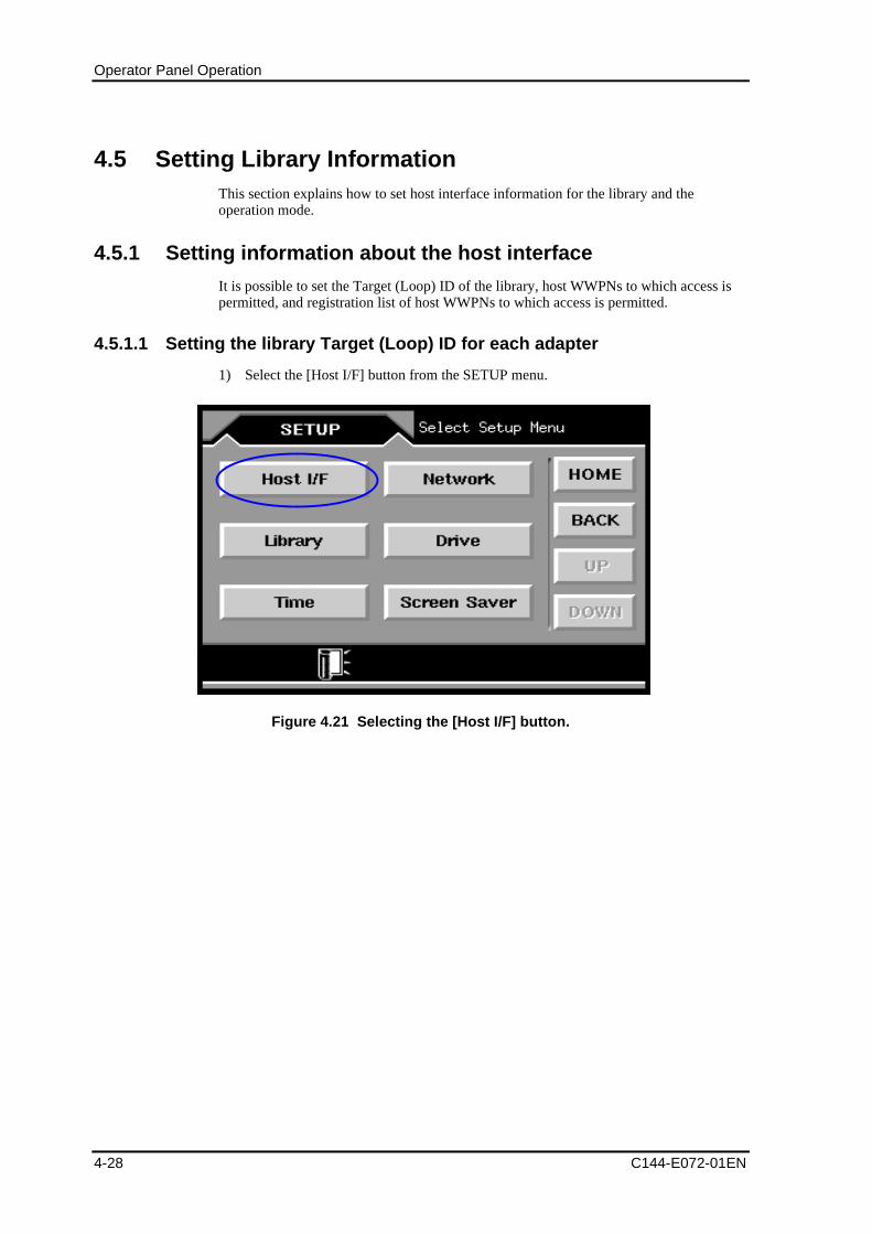
Operator Panel Operation
4-28 C144-E072-01EN
4.5 Setting Library InformationThis section explains how to set host interface information for the library and theoperation mode.
4.5.1 Setting information about the host interface
It is possible to set the Target (Loop) ID of the library, host WWPNs to which access ispermitted, and registration list of host WWPNs to which access is permitted.
4.5.1.1 Setting the library Target (Loop) ID for each adapter
1) Select the [Host I/F] button from the SETUP menu.
Figure 4.21 Selecting the [Host I/F] button.
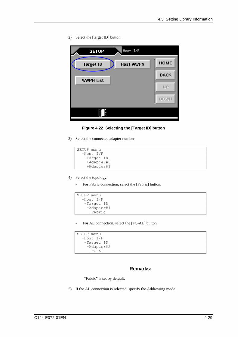
4.5 Setting Library Information
C144-E072-01EN 4-29
2) Select the [target ID] button.
Figure 4.22 Selecting the [Target ID] button
3) Select the connected adapter number
SETUP menu -Host I/F -Target ID +Adapter#0 +Adapter#1
4) Select the topology.
- For Fabric connection, select the [Fabric] button.
SETUP menu -Host I/F -Target ID -Adapter#1 +Fabric
- For AL connection, select the [FC-AL] button.
SETUP menu -Host I/F -Target ID -Adapter#2 +FC-AL
Remarks:
"Fabric" is set by default.
5) If the AL connection is selected, specify the Addressing mode.
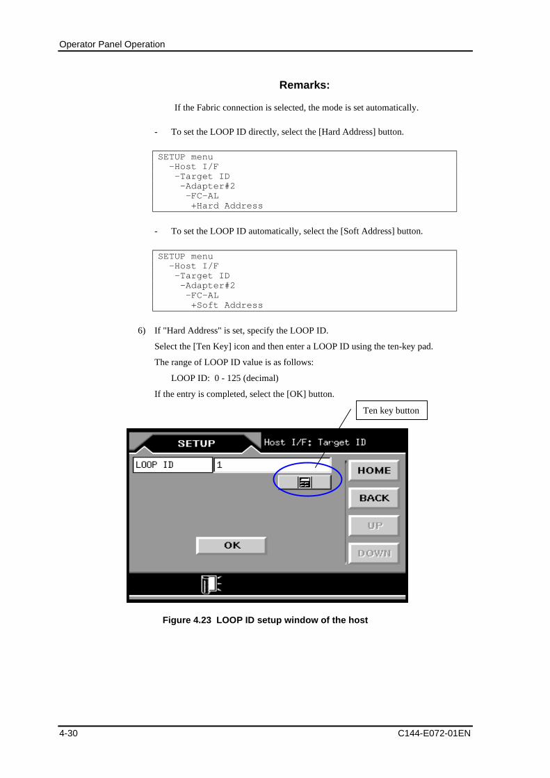
Operator Panel Operation
4-30 C144-E072-01EN
Remarks:
If the Fabric connection is selected, the mode is set automatically.
- To set the LOOP ID directly, select the [Hard Address] button.
SETUP menu -Host I/F -Target ID -Adapter#2 -FC-AL +Hard Address
- To set the LOOP ID automatically, select the [Soft Address] button.
SETUP menu -Host I/F -Target ID -Adapter#2 -FC-AL +Soft Address
6) If "Hard Address" is set, specify the LOOP ID.
Select the [Ten Key] icon and then enter a LOOP ID using the ten-key pad.
The range of LOOP ID value is as follows:
LOOP ID: 0 - 125 (decimal)
If the entry is completed, select the [OK] button.
Figure 4.23 LOOP ID setup window of the host
Ten key button
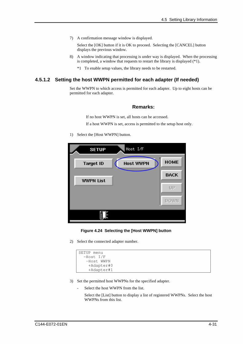
4.5 Setting Library Information
C144-E072-01EN 4-31
7) A confirmation message window is displayed.
Select the [OK] button if it is OK to proceed. Selecting the [CANCEL] buttondisplays the previous window.
8) A window indicating that processing is under way is displayed. When the processingis completed, a window that requests to restart the library is displayed (*1).
*1 To enable setup values, the library needs to be restarted.
4.5.1.2 Setting the host WWPN permitted for each adapter (If needed)
Set the WWPN to which access is permitted for each adapter. Up to eight hosts can bepermitted for each adapter.
Remarks:
If no host WWPN is set, all hosts can be accessed.
If a host WWPN is set, access is permitted to the setup host only.
1) Select the [Host WWPN] button.
Figure 4.24 Selecting the [Host WWPN] button
2) Select the connected adapter number.
SETUP menu -Host I/F -Host WWPN +Adapter#0 +Adapter#1
3) Set the permitted host WWPNs for the specified adapter.
- Select the host WWPN from the list.
Select the [List] button to display a list of registered WWPNs. Select the hostWWPNs from this list.
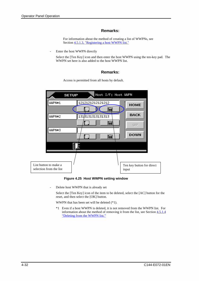
Operator Panel Operation
4-32 C144-E072-01EN
Remarks:
For information about the method of creating a list of WWPNs, seeSection 4.5.1.3, "Registering a host WWPN list."
- Enter the host WWPN directly
Select the [Ten Key] icon and then enter the host WWPN using the ten-key pad. TheWWPN set here is also added to the host WWPN list.
Remarks:
Access is permitted from all hosts by default.
Figure 4.25 Host WWPN setting window
- Delete host WWPN that is already set
Select the [Ten Key] icon of the item to be deleted, select the [AC] button for thereset, and then select the [OK] button.
WWPN that has been set will be deleted (*1).
*1 Even if a host WWPN is deleted, it is not removed from the WWPN list. Forinformation about the method of removing it from the list, see Section 4.5.1.4“Deleting from the WWPN list.”
List button to make aselection from the list
Ten key button for directinput
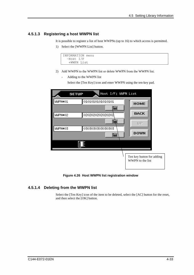
4.5 Setting Library Information
C144-E072-01EN 4-33
4.5.1.3 Registering a host WWPN list
It is possible to register a list of host WWPNs (up to 16) to which access is permitted.
1) Select the [WWPN List] button.
INFORMATION menu -Host I/F +WWPN List
2) Add WWPN to the WWPN list or delete WWPN from the WWPN list.
- Adding to the WWPN list
Select the [Ten Key] icon and enter WWPN using the ten-key pad.
Figure 4.26 Host WWPN list registration window
4.5.1.4 Deleting from the WWPN list
Select the [Ten Key] icon of the item to be deleted, select the [AC] button for the reset,and then select the [OK] button.
Ten key button for addingWWPN to the list
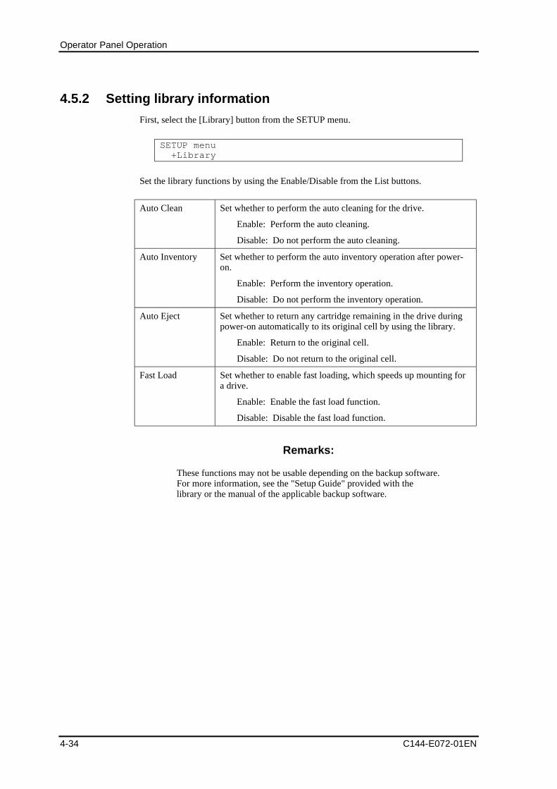
Operator Panel Operation
4-34 C144-E072-01EN
4.5.2 Setting library information
First, select the [Library] button from the SETUP menu.
SETUP menu +Library
Set the library functions by using the Enable/Disable from the List buttons.
Auto Clean Set whether to perform the auto cleaning for the drive.
Enable: Perform the auto cleaning.
Disable: Do not perform the auto cleaning.
Auto Inventory Set whether to perform the auto inventory operation after power-on.
Enable: Perform the inventory operation.
Disable: Do not perform the inventory operation.
Auto Eject Set whether to return any cartridge remaining in the drive duringpower-on automatically to its original cell by using the library.
Enable: Return to the original cell.
Disable: Do not return to the original cell.
Fast Load Set whether to enable fast loading, which speeds up mounting fora drive.
Enable: Enable the fast load function.
Disable: Disable the fast load function.
Remarks:
These functions may not be usable depending on the backup software.For more information, see the "Setup Guide" provided with thelibrary or the manual of the applicable backup software.
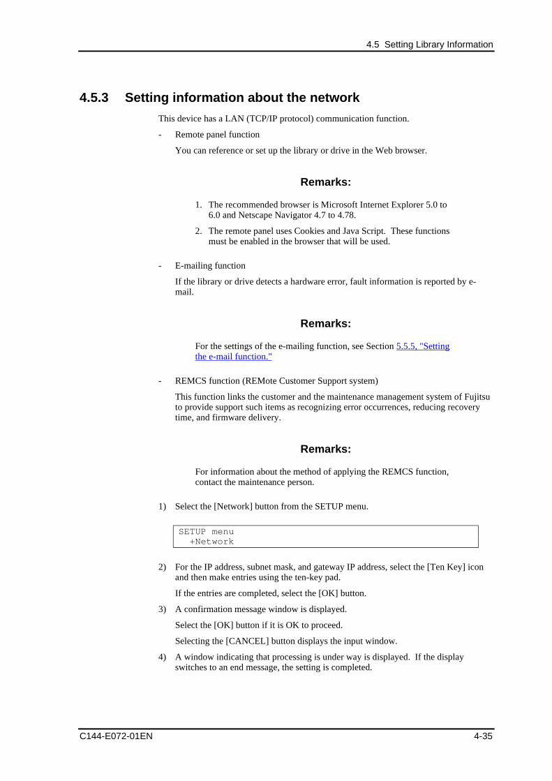
4.5 Setting Library Information
C144-E072-01EN 4-35
4.5.3 Setting information about the network
This device has a LAN (TCP/IP protocol) communication function.
- Remote panel function
You can reference or set up the library or drive in the Web browser.
Remarks:
1. The recommended browser is Microsoft Internet Explorer 5.0 to6.0 and Netscape Navigator 4.7 to 4.78.
2. The remote panel uses Cookies and Java Script. These functionsmust be enabled in the browser that will be used.
- E-mailing function
If the library or drive detects a hardware error, fault information is reported by e-mail.
Remarks:
For the settings of the e-mailing function, see Section 5.5.5, "Settingthe e-mail function."
- REMCS function (REMote Customer Support system)
This function links the customer and the maintenance management system of Fujitsuto provide support such items as recognizing error occurrences, reducing recoverytime, and firmware delivery.
Remarks:
For information about the method of applying the REMCS function,contact the maintenance person.
1) Select the [Network] button from the SETUP menu.
SETUP menu +Network
2) For the IP address, subnet mask, and gateway IP address, select the [Ten Key] iconand then make entries using the ten-key pad.
If the entries are completed, select the [OK] button.
3) A confirmation message window is displayed.
Select the [OK] button if it is OK to proceed.
Selecting the [CANCEL] button displays the input window.
4) A window indicating that processing is under way is displayed. If the displayswitches to an end message, the setting is completed.
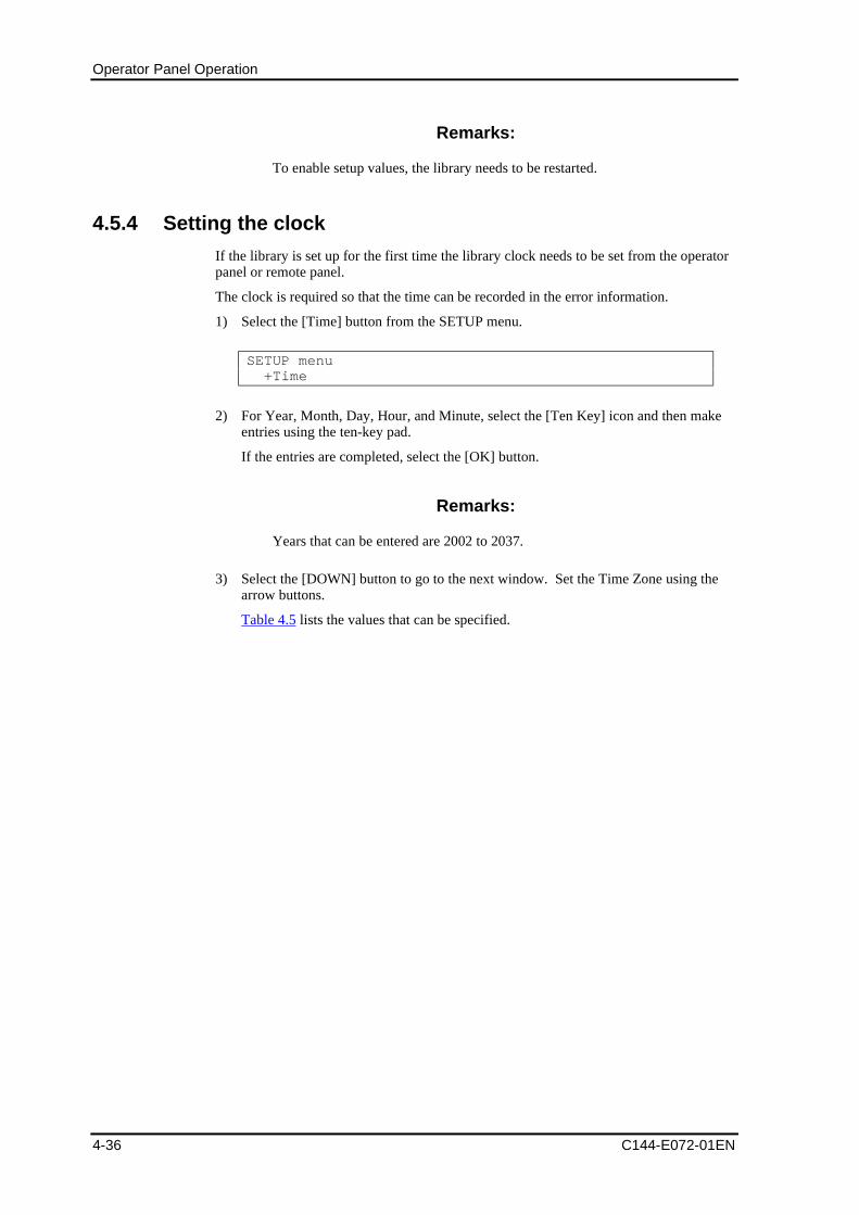
Operator Panel Operation
4-36 C144-E072-01EN
Remarks:
To enable setup values, the library needs to be restarted.
4.5.4 Setting the clock
If the library is set up for the first time the library clock needs to be set from the operatorpanel or remote panel.
The clock is required so that the time can be recorded in the error information.
1) Select the [Time] button from the SETUP menu.
SETUP menu +Time
2) For Year, Month, Day, Hour, and Minute, select the [Ten Key] icon and then makeentries using the ten-key pad.
If the entries are completed, select the [OK] button.
Remarks:
Years that can be entered are 2002 to 2037.
3) Select the [DOWN] button to go to the next window. Set the Time Zone using thearrow buttons.
Table 4.5 lists the values that can be specified.
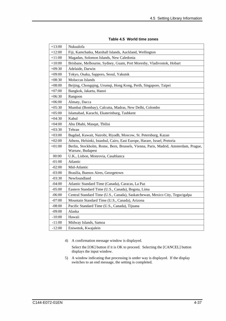
4.5 Setting Library Information
C144-E072-01EN 4-37
Table 4.5 World time zones
+13:00 Nukualofa
+12:00 Fiji, Kamchatka, Marshall Islands, Auckland, Wellington
+11:00 Magadan, Solomon Islands, New Caledonia
+10:00 Brisbane, Melbourne, Sydney, Guam, Port Moresby, Vladivostok, Hobart
+09:30 Adelaide, Darwin
+09:00 Tokyo, Osaka, Sapporo, Seoul, Yakutsk
+08:30 Moluccas Islands
+08:00 Beijing, Chongqing, Urumqi, Hong Kong, Perth, Singapore, Taipei
+07:00 Bangkok, Jakarta, Hanoi
+06:30 Rangoon
+06:00 Almaty, Dacca
+05:30 Mumbai (Bombay), Calcutta, Madras, New Delhi, Colombo
+05:00 Islamabad, Karachi, Ekaterinburg, Tashkent
+04:30 Kabul
+04:00 Abu Dhabi, Masqat, Tbilisi
+03:30 Tehran
+03:00 Bagdad, Kuwait, Nairobi, Riyadh, Moscow, St. Petersburg, Kazan
+02:00 Athens, Helsinki, Istanbul, Cairo, East Europe, Harare, Israel, Pretoria
+01:00 Berlin, Stockholm, Rome, Bern, Brussels, Vienna, Paris, Madrid, Amsterdam, Prague,Warsaw, Budapest
00:00 U.K., Lisbon, Monrovia, Casablanca
-01:00 Atlantic
-02:00 Mid-Atlantic
-03:00 Brasilia, Buenos Aires, Georgetown
-03:30 Newfoundland
-04:00 Atlantic Standard Time (Canada), Caracas, La Paz
-05:00 Eastern Standard Time (U.S., Canada), Bogota, Lima
-06:00 Central Standard Time (U.S., Canada), Saskatchewan, Mexico City, Tegucigalpa
-07:00 Mountain Standard Time (U.S., Canada), Arizona
-08:00 Pacific Standard Time (U.S., Canada), Tijuana
-09:00 Alaska
-10:00 Hawaii
-11:00 Midway Islands, Samoa
-12:00 Eniwetok, Kwajalein
4) A confirmation message window is displayed.
Select the [OK] button if it is OK to proceed. Selecting the [CANCEL] buttondisplays the input window.
5) A window indicating that processing is under way is displayed. If the displayswitches to an end message, the setting is completed.
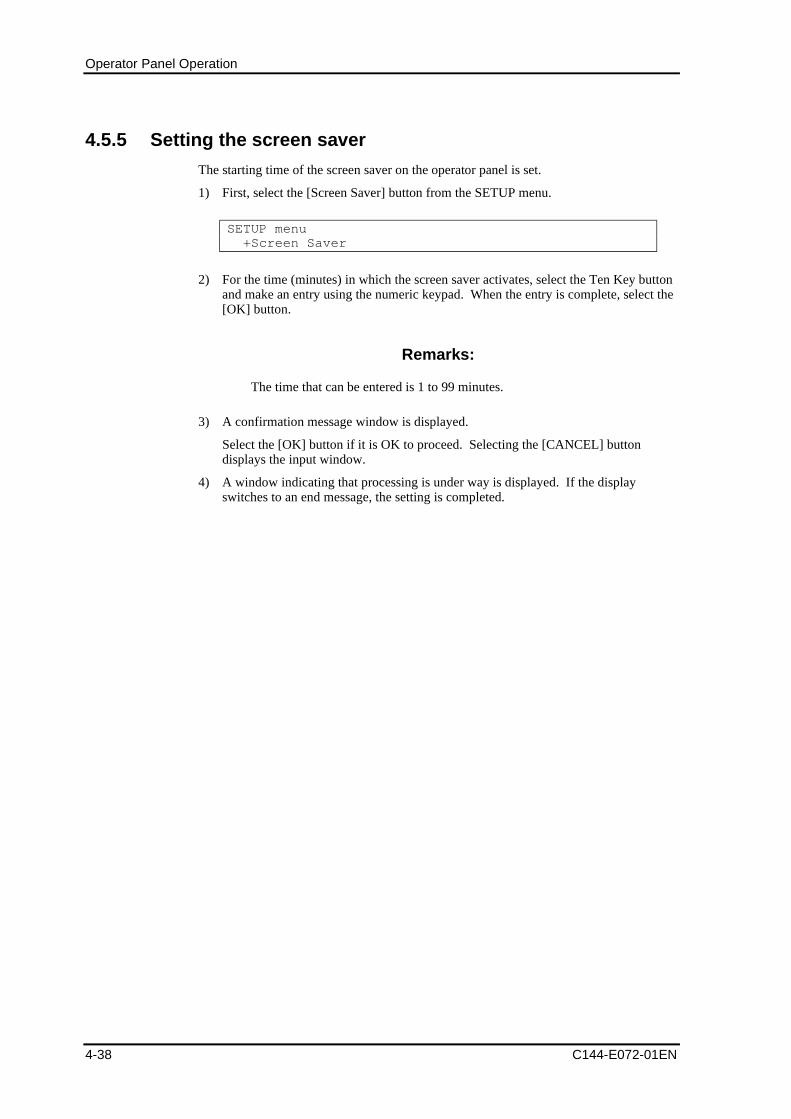
Operator Panel Operation
4-38 C144-E072-01EN
4.5.5 Setting the screen saver
The starting time of the screen saver on the operator panel is set.
1) First, select the [Screen Saver] button from the SETUP menu.
SETUP menu +Screen Saver
2) For the time (minutes) in which the screen saver activates, select the Ten Key buttonand make an entry using the numeric keypad. When the entry is complete, select the[OK] button.
Remarks:
The time that can be entered is 1 to 99 minutes.
3) A confirmation message window is displayed.
Select the [OK] button if it is OK to proceed. Selecting the [CANCEL] buttondisplays the input window.
4) A window indicating that processing is under way is displayed. If the displayswitches to an end message, the setting is completed.
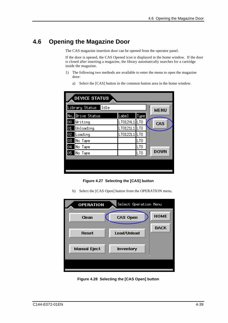
4.6 Opening the Magazine Door
C144-E072-01EN 4-39
4.6 Opening the Magazine DoorThe CAS magazine insertion door can be opened from the operator panel.
If the door is opened, the CAS Opened icon is displayed in the home window. If the dooris closed after inserting a magazine, the library automatically searches for a cartridgeinside the magazine.
1) The following two methods are available to enter the menu to open the magazinedoor:
a) Select the [CAS] button in the common button area in the home window.
Figure 4.27 Selecting the [CAS] button
b) Select the [CAS Open] button from the OPERATION menu.
Figure 4.28 Selecting the [CAS Open] button
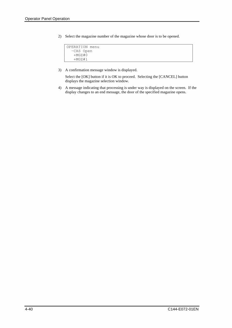
Operator Panel Operation
4-40 C144-E072-01EN
2) Select the magazine number of the magazine whose door is to be opened.
OPERATION menu -CAS Open +MGZ#0 +MGZ#1
3) A confirmation message window is displayed.
Select the [OK] button if it is OK to proceed. Selecting the [CANCEL] buttondisplays the magazine selection window.
4) A message indicating that processing is under way is displayed on the screen. If thedisplay changes to an end message, the door of the specified magazine opens.
4.7 Loading/Unloading a Cartridge
C144-E072-01EN 4-41
4.7 Loading/Unloading a CartridgeA cartridge inside the magazine is loaded into the drive or a cartridge loaded into thedrive is unloaded into the magazine.
CAUTION
Data loss:If a drive is used for the load/unload operation, the drive cannot beused from backup software.
Be sure to stop the operation of backup software before performingthe load/unload operation.
4.7.1 Loading a cartridge contained in the magazine into thedrive
1) Select the [Load/Unload] button from the OPERATION menu.
OPERATION menu +Load/Unload
2) Press the [Load] button.
3) Select a magazine.
When a magazine is selected, the door of the specified magazine opens.
OPERATION menu -Load/Unload -Load +MGZ#0 +MGZ#1
4) Specify a cartridge inside the specified magazine using a label number (more thanone cartridge may be specified).
OPERATION menu -Load/Unload -Load -MGZ#0 +LTO0062L1 +LTO0063L1
5) Specify a drive to be loaded (you can specify as many drives as the cartridgesspecified above).
OPERATION menu -Load -MGZ#0 +LTO0062L1 +LTO0063L1 +DRV#01 +DRV#02
Operator Panel Operation
4-42 C144-E072-01EN
6) A confirmation message window is displayed.
Select the [OK] button if it is OK to proceed. Selecting the [CANCEL] buttondisplays the drive designation window.
7) A message indicating that processing is under way is displayed on the screen. If thedisplay changes to an end message, loading to the specified drive is completed.
4.7.2 Unloading a cartridge loaded from the magazine
A cartridge in the drive loaded using the Load/Unload menu is unloaded into thespecified magazine.
Remarks:
If no load/unload operation was performed using the Load/Unloadmenu before, this unload operation cannot be performed.
CAUTION
Data loss:If a drive is used for the load/unload operation, the drive cannot beused from backup software.
Be sure to stop the operation of backup software before performingthe load/unload operation.
1) Select the [Load/Unload] button from the OPERATION menu.
OPERATION menu +Load/Unload
2) Specify a drive to be unloaded (more than one drive may be specified).
3) Specify the magazine to be unloaded.
OPERATION menu -Load/Unload -DRV#00 -DRV#01 +MGZ#0 +MGZ#1
4) A confirmation message window is displayed.
Select the [OK] button if it is OK to proceed. Selecting the [CANCEL] buttondisplays the magazine selection window.
5) A message indicating that processing is under way is displayed on the screen. If thedisplay changes to an end message, unloading from the specified drive is completed.
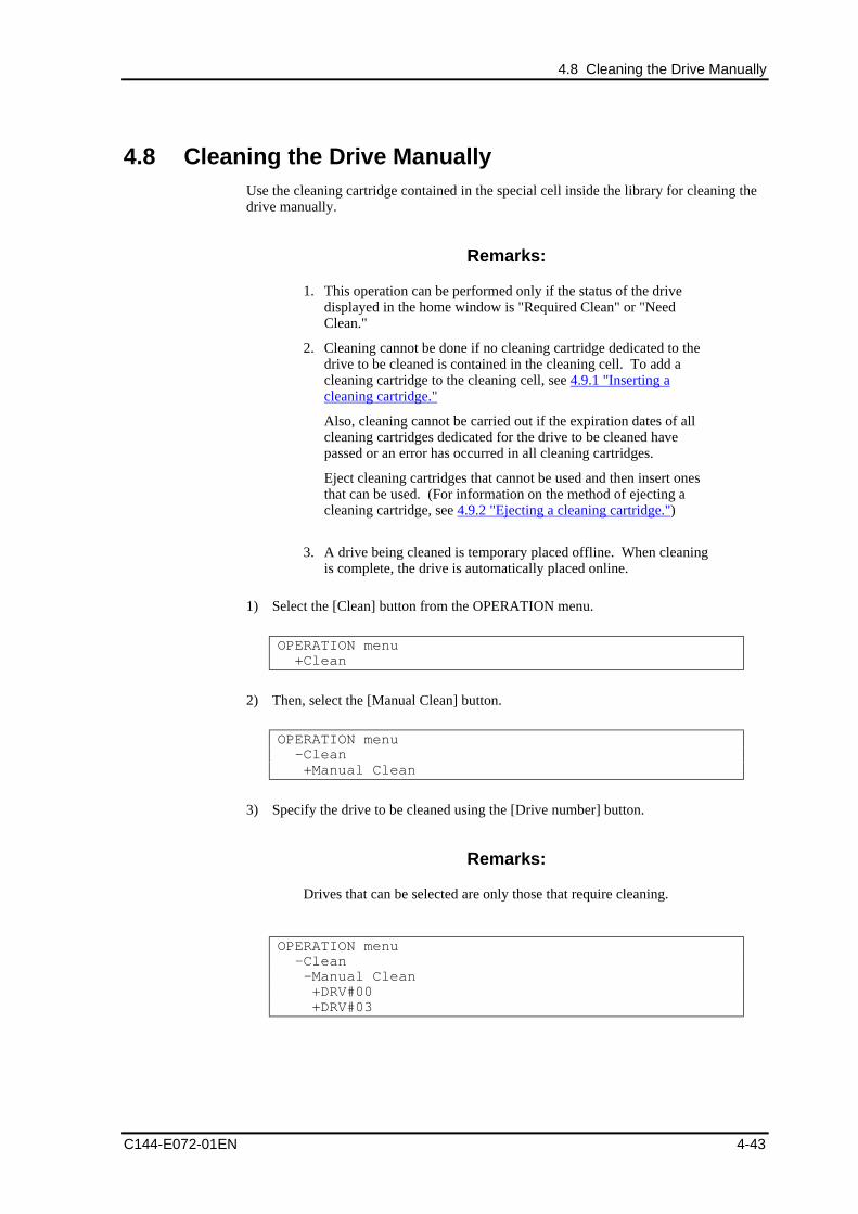
4.8 Cleaning the Drive Manually
C144-E072-01EN 4-43
4.8 Cleaning the Drive ManuallyUse the cleaning cartridge contained in the special cell inside the library for cleaning thedrive manually.
Remarks:
1. This operation can be performed only if the status of the drivedisplayed in the home window is "Required Clean" or "NeedClean."
2. Cleaning cannot be done if no cleaning cartridge dedicated to thedrive to be cleaned is contained in the cleaning cell. To add acleaning cartridge to the cleaning cell, see 4.9.1 "Inserting acleaning cartridge."
Also, cleaning cannot be carried out if the expiration dates of allcleaning cartridges dedicated for the drive to be cleaned havepassed or an error has occurred in all cleaning cartridges.
Eject cleaning cartridges that cannot be used and then insert onesthat can be used. (For information on the method of ejecting acleaning cartridge, see 4.9.2 "Ejecting a cleaning cartridge.")
3. A drive being cleaned is temporary placed offline. When cleaningis complete, the drive is automatically placed online.
1) Select the [Clean] button from the OPERATION menu.
OPERATION menu +Clean
2) Then, select the [Manual Clean] button.
OPERATION menu -Clean +Manual Clean
3) Specify the drive to be cleaned using the [Drive number] button.
Remarks:
Drives that can be selected are only those that require cleaning.
OPERATION menu -Clean -Manual Clean +DRV#00 +DRV#03
Operator Panel Operation
4-44 C144-E072-01EN
4) A confirmation message window is displayed.
Select the [OK] button if it is OK to proceed. Selecting the [CANCEL] buttondisplays the drive designation window.
5) A message indicating that processing is under way is displayed on the screen. If thedisplay changes to an end message, cleaning of the specified drive is completed.
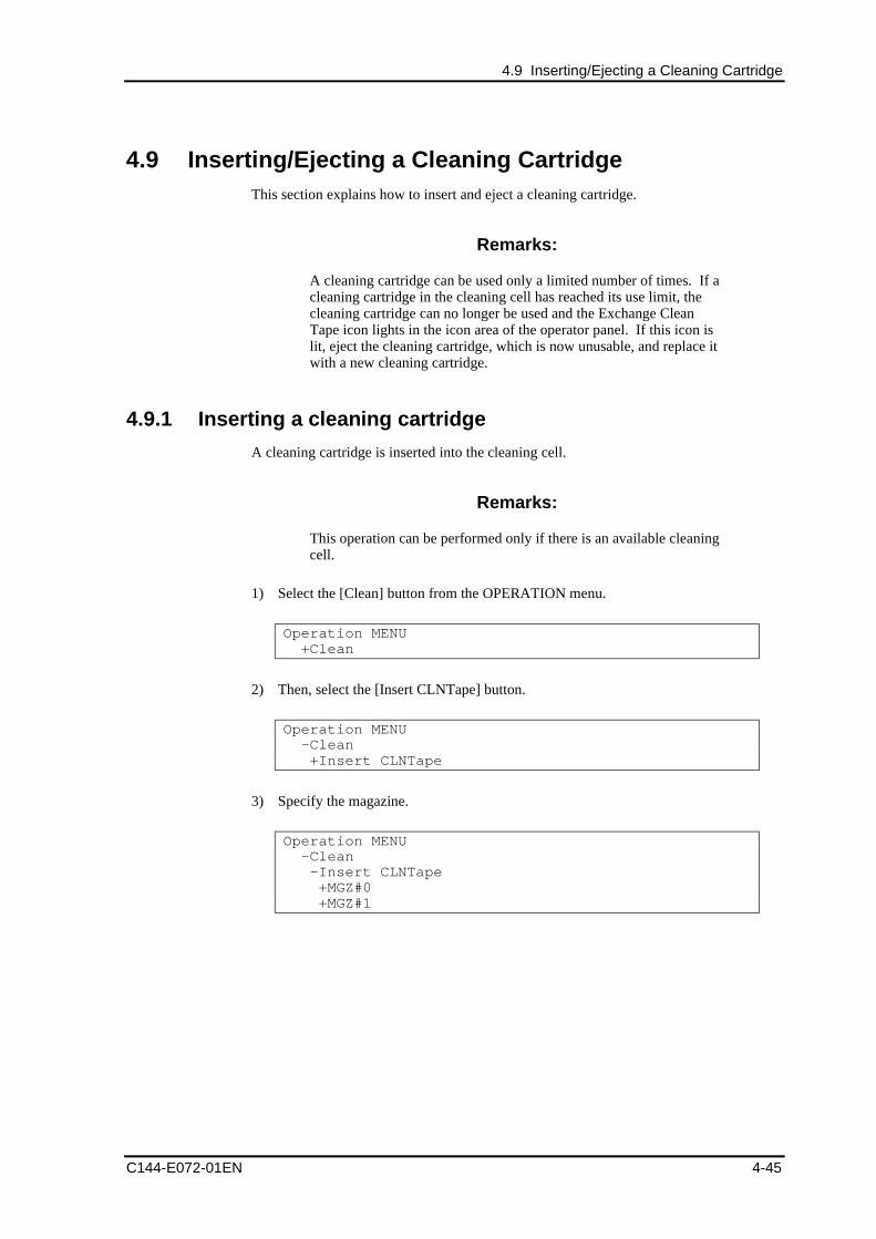
4.9 Inserting/Ejecting a Cleaning Cartridge
C144-E072-01EN 4-45
4.9 Inserting/Ejecting a Cleaning CartridgeThis section explains how to insert and eject a cleaning cartridge.
Remarks:
A cleaning cartridge can be used only a limited number of times. If acleaning cartridge in the cleaning cell has reached its use limit, thecleaning cartridge can no longer be used and the Exchange CleanTape icon lights in the icon area of the operator panel. If this icon islit, eject the cleaning cartridge, which is now unusable, and replace itwith a new cleaning cartridge.
4.9.1 Inserting a cleaning cartridge
A cleaning cartridge is inserted into the cleaning cell.
Remarks:
This operation can be performed only if there is an available cleaningcell.
1) Select the [Clean] button from the OPERATION menu.
Operation MENU +Clean
2) Then, select the [Insert CLNTape] button.
Operation MENU -Clean +Insert CLNTape
3) Specify the magazine.
Operation MENU -Clean -Insert CLNTape +MGZ#0 +MGZ#1
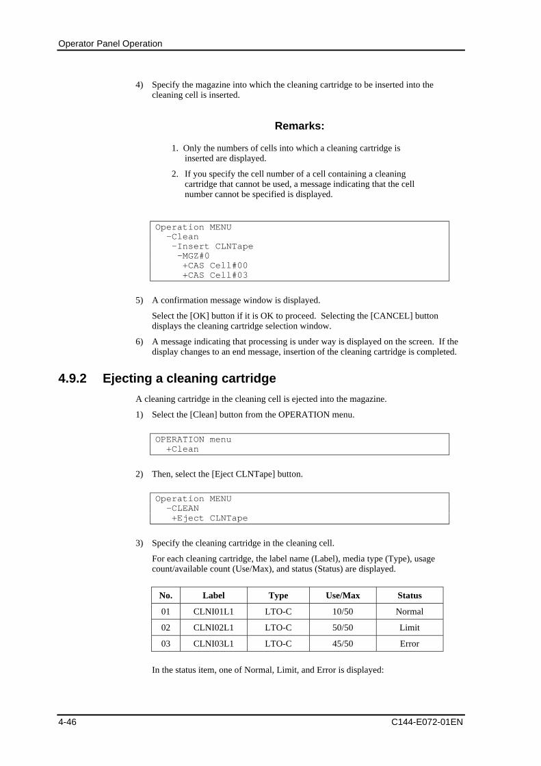
Operator Panel Operation
4-46 C144-E072-01EN
4) Specify the magazine into which the cleaning cartridge to be inserted into thecleaning cell is inserted.
Remarks:
1. Only the numbers of cells into which a cleaning cartridge isinserted are displayed.
2. If you specify the cell number of a cell containing a cleaningcartridge that cannot be used, a message indicating that the cellnumber cannot be specified is displayed.
Operation MENU -Clean -Insert CLNTape -MGZ#0 +CAS Cell#00 +CAS Cell#03
5) A confirmation message window is displayed.
Select the [OK] button if it is OK to proceed. Selecting the [CANCEL] buttondisplays the cleaning cartridge selection window.
6) A message indicating that processing is under way is displayed on the screen. If thedisplay changes to an end message, insertion of the cleaning cartridge is completed.
4.9.2 Ejecting a cleaning cartridge
A cleaning cartridge in the cleaning cell is ejected into the magazine.
1) Select the [Clean] button from the OPERATION menu.
OPERATION menu +Clean
2) Then, select the [Eject CLNTape] button.
Operation MENU -CLEAN +Eject CLNTape
3) Specify the cleaning cartridge in the cleaning cell.
For each cleaning cartridge, the label name (Label), media type (Type), usagecount/available count (Use/Max), and status (Status) are displayed.
No. Label Type Use/Max Status
01 CLNI01L1 LTO-C 10/50 Normal
02 CLNI02L1 LTO-C 50/50 Limit
03 CLNI03L1 LTO-C 45/50 Error
In the status item, one of Normal, Limit, and Error is displayed:
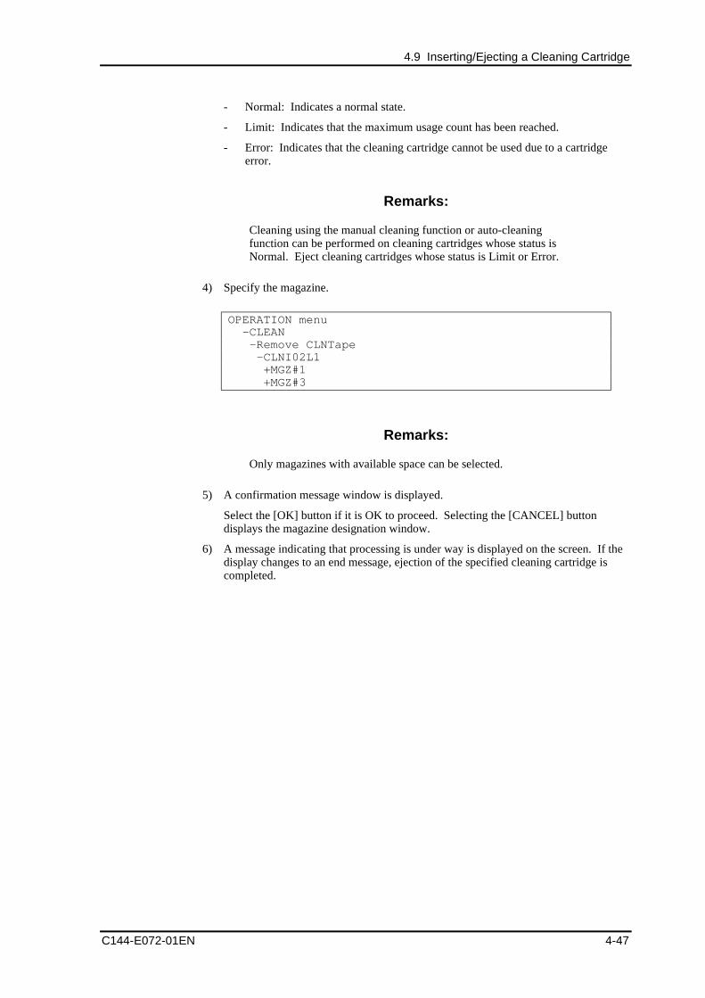
4.9 Inserting/Ejecting a Cleaning Cartridge
C144-E072-01EN 4-47
- Normal: Indicates a normal state.
- Limit: Indicates that the maximum usage count has been reached.
- Error: Indicates that the cleaning cartridge cannot be used due to a cartridgeerror.
Remarks:
Cleaning using the manual cleaning function or auto-cleaningfunction can be performed on cleaning cartridges whose status isNormal. Eject cleaning cartridges whose status is Limit or Error.
4) Specify the magazine.
OPERATION menu -CLEAN -Remove CLNTape -CLNI02L1 +MGZ#1 +MGZ#3
Remarks:
Only magazines with available space can be selected.
5) A confirmation message window is displayed.
Select the [OK] button if it is OK to proceed. Selecting the [CANCEL] buttondisplays the magazine designation window.
6) A message indicating that processing is under way is displayed on the screen. If thedisplay changes to an end message, ejection of the specified cleaning cartridge iscompleted.
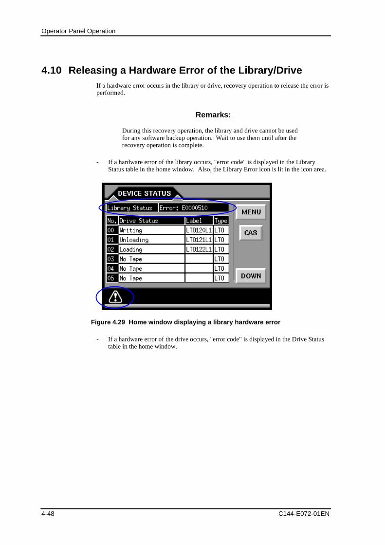
Operator Panel Operation
4-48 C144-E072-01EN
4.10 Releasing a Hardware Error of the Library/DriveIf a hardware error occurs in the library or drive, recovery operation to release the error isperformed.
Remarks:
During this recovery operation, the library and drive cannot be usedfor any software backup operation. Wait to use them until after therecovery operation is complete.
- If a hardware error of the library occurs, "error code" is displayed in the LibraryStatus table in the home window. Also, the Library Error icon is lit in the icon area.
Figure 4.29 Home window displaying a library hardware error
- If a hardware error of the drive occurs, "error code" is displayed in the Drive Statustable in the home window.
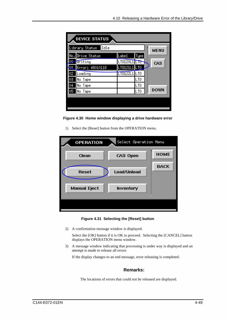
4.10 Releasing a Hardware Error of the Library/Drive
C144-E072-01EN 4-49
Figure 4.30 Home window displaying a drive hardware error
1) Select the [Reset] button from the OPERATION menu.
Figure 4.31 Selecting the [Reset] button
2) A confirmation message window is displayed.
Select the [OK] button if it is OK to proceed. Selecting the [CANCEL] buttondisplays the OPERATION menu window.
3) A message window indicating that processing is under way is displayed and anattempt is made to release all errors
If the display changes to an end message, error releasing is completed.
Remarks:
The locations of errors that could not be released are displayed.
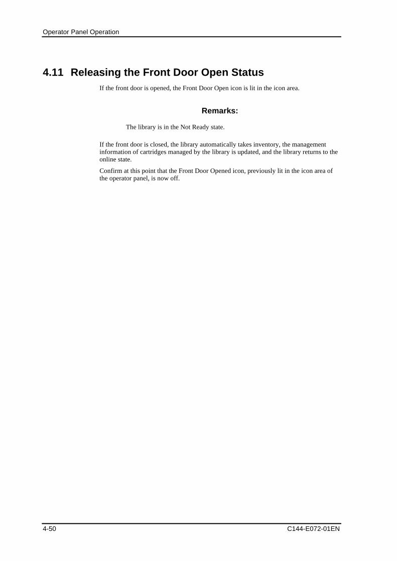
Operator Panel Operation
4-50 C144-E072-01EN
4.11 Releasing the Front Door Open StatusIf the front door is opened, the Front Door Open icon is lit in the icon area.
Remarks:
The library is in the Not Ready state.
If the front door is closed, the library automatically takes inventory, the managementinformation of cartridges managed by the library is updated, and the library returns to theonline state.
Confirm at this point that the Front Door Opened icon, previously lit in the icon area ofthe operator panel, is now off.
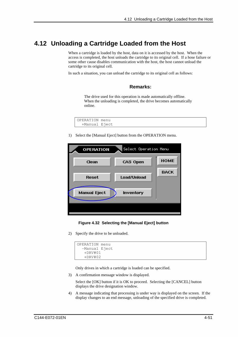
4.12 Unloading a Cartridge Loaded from the Host
C144-E072-01EN 4-51
4.12 Unloading a Cartridge Loaded from the HostWhen a cartridge is loaded by the host, data on it is accessed by the host. When theaccess is completed, the host unloads the cartridge to its original cell. If a hose failure orsome other cause disables communication with the host, the host cannot unload thecartridge to its original cell.
In such a situation, you can unload the cartridge to its original cell as follows:
Remarks:
The drive used for this operation is made automatically offline.When the unloading is completed, the drive becomes automaticallyonline.
OPERATION menu +Manual Eject
1) Select the [Manual Eject] button from the OPERATION menu.
Figure 4.32 Selecting the [Manual Eject] button
2) Specify the drive to be unloaded.
OPERATION menu -Manual Eject +DRV#01 +DRV#02
Only drives in which a cartridge is loaded can be specified.
3) A confirmation message window is displayed.
Select the [OK] button if it is OK to proceed. Selecting the [CANCEL] buttondisplays the drive designation window.
4) A message indicating that processing is under way is displayed on the screen. If thedisplay changes to an end message, unloading of the specified drive is completed.
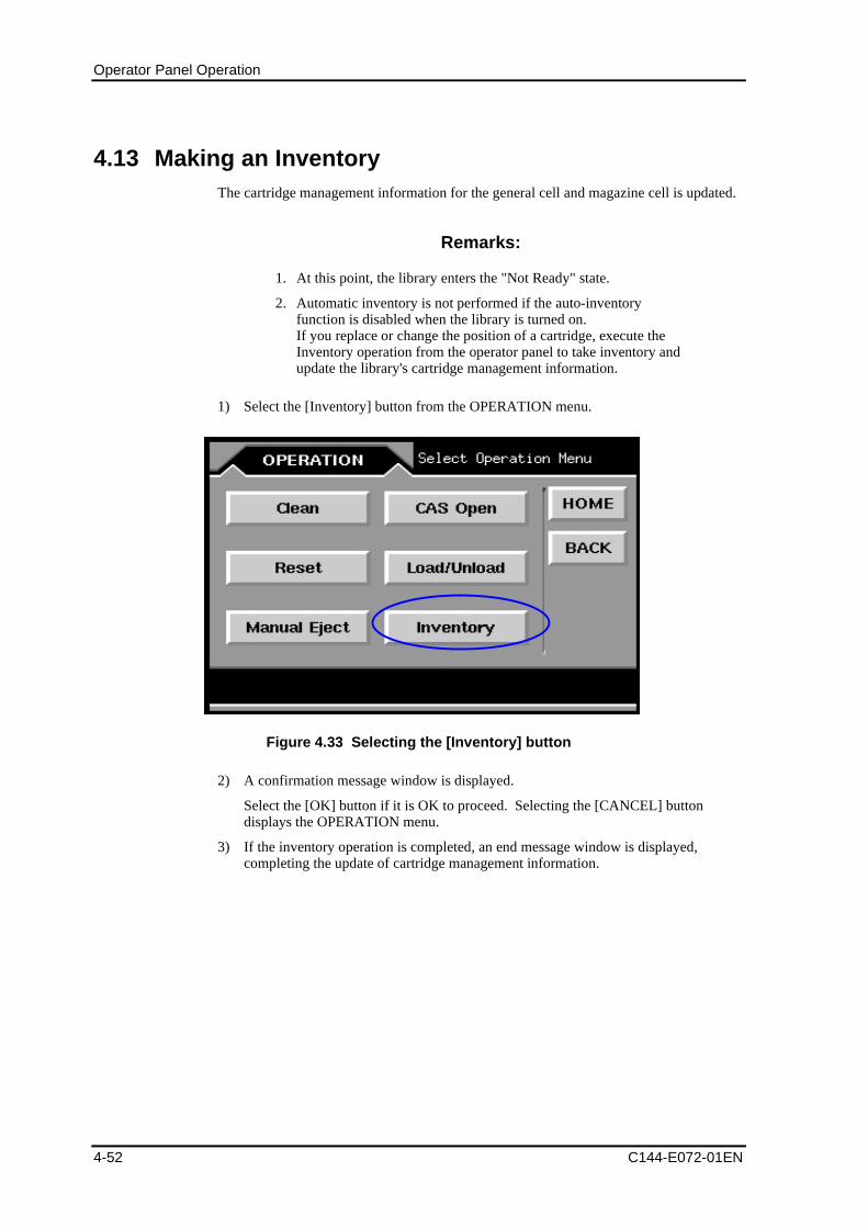
Operator Panel Operation
4-52 C144-E072-01EN
4.13 Making an InventoryThe cartridge management information for the general cell and magazine cell is updated.
Remarks:
1. At this point, the library enters the "Not Ready" state.
2. Automatic inventory is not performed if the auto-inventoryfunction is disabled when the library is turned on.If you replace or change the position of a cartridge, execute theInventory operation from the operator panel to take inventory andupdate the library's cartridge management information.
1) Select the [Inventory] button from the OPERATION menu.
Figure 4.33 Selecting the [Inventory] button
2) A confirmation message window is displayed.
Select the [OK] button if it is OK to proceed. Selecting the [CANCEL] buttondisplays the OPERATION menu.
3) If the inventory operation is completed, an end message window is displayed,completing the update of cartridge management information.
C144-E072-01EN 5-1
Chapter 5 Remote Panel Operation
5.1 Overview
5.2 Referencing the Status of Drive/Library
5.3 Referencing Library Information
5.4 Setting Target ID of the Drive
5.5 Setting Library Information
5.6 Operating the Library
5.1 OverviewThe remote panel can be used to perform operations such as the library and drive statusreference, library and drive settings, and drive cleaning from the general-purpose browser(*1) such as PC via LAN.
*1 The recommended browser is Microsoft Internet Explorer 5.0 to 6.0 and NetscapeNavigator 4.7 to 4.78.
Before using the remote panel, you need to make network settings from the operatorpanel to set to be enabled an IP address, subnet mask, and gateway. After making thesettings, restart the library and specify the following URL:
http:// <IP address specified for the library>
The window shown in Figure 5.1 is displayed.
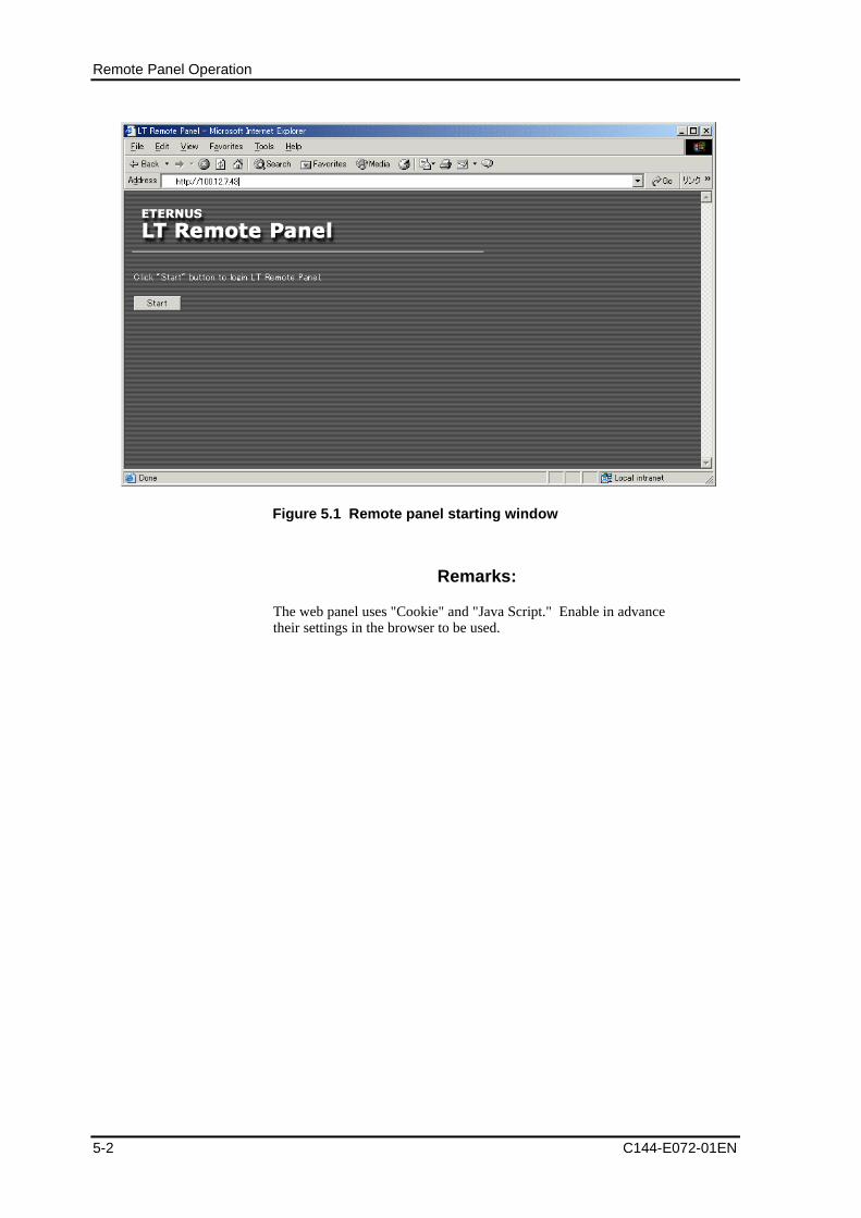
Remote Panel Operation
5-2 C144-E072-01EN
Figure 5.1 Remote panel starting window
Remarks:
The web panel uses "Cookie" and "Java Script." Enable in advancetheir settings in the browser to be used.
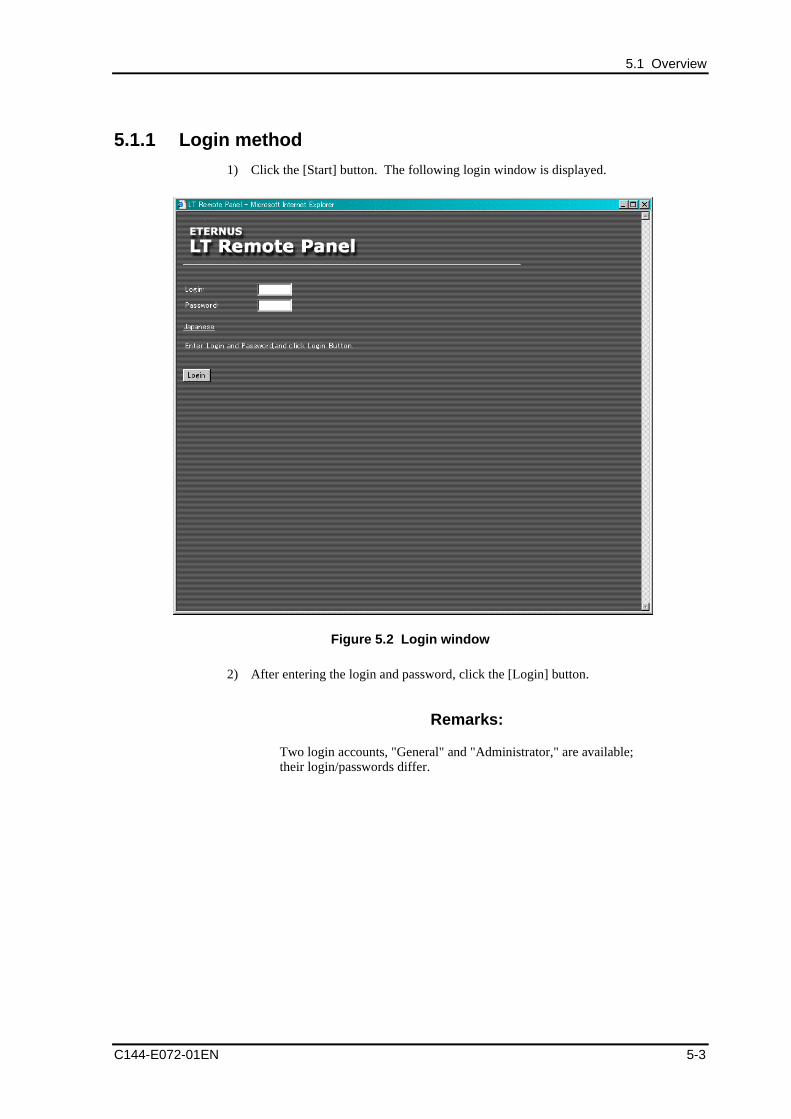
5.1 Overview
C144-E072-01EN 5-3
5.1.1 Login method
1) Click the [Start] button. The following login window is displayed.
Figure 5.2 Login window
2) After entering the login and password, click the [Login] button.
Remarks:
Two login accounts, "General" and "Administrator," are available;their login/passwords differ.
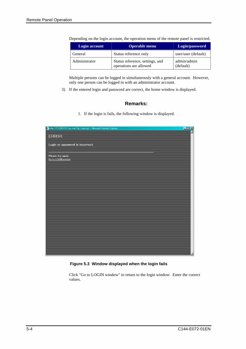
Remote Panel Operation
5-4 C144-E072-01EN
Depending on the login account, the operation menu of the remote panel is restricted.
Login account Operable menu Login/password
General Status reference only user/user (default)
Administrator Status reference, settings, andoperations are allowed
admin/admin(default)
Multiple persons can be logged in simultaneously with a general account. However,only one person can be logged in with an administrator account.
3) If the entered login and password are correct, the home window is displayed.
Remarks:
1. If the login is fails, the following window is displayed.
Figure 5.3 Window displayed when the login fails
Click "Go to LOGIN window" to return to the login window. Enter the correctvalues.
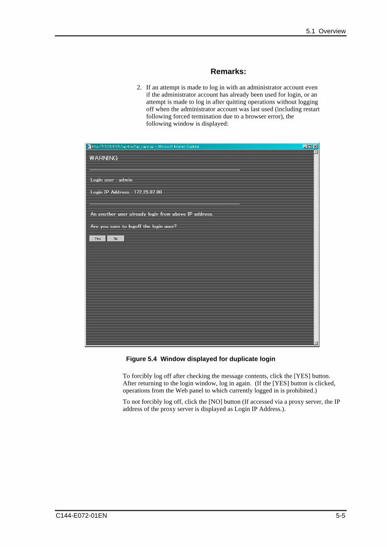
5.1 Overview
C144-E072-01EN 5-5
Remarks:
2. If an attempt is made to log in with an administrator account evenif the administrator account has already been used for login, or anattempt is made to log in after quitting operations without loggingoff when the administrator account was last used (including restartfollowing forced termination due to a browser error), thefollowing window is displayed:
Figure 5.4 Window displayed for duplicate login
To forcibly log off after checking the message contents, click the [YES] button.After returning to the login window, log in again. (If the [YES] button is clicked,operations from the Web panel to which currently logged in is prohibited.)
To not forcibly log off, click the [NO] button (If accessed via a proxy server, the IPaddress of the proxy server is displayed as Login IP Address.).
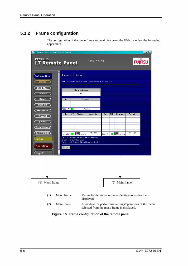
Remote Panel Operation
5-6 C144-E072-01EN
5.1.2 Frame configuration
The configuration of the menu frame and main frame on the Web panel has the followingappearance:
(1) Menu frame (2) Main frame
(1) Menu frame Menus for the status reference/settings/operations aredisplayed.
(2) Main frame A window for performing settings/operations of the menuselected from the menu frame is displayed.
Figure 5.5 Frame configuration of the remote panel
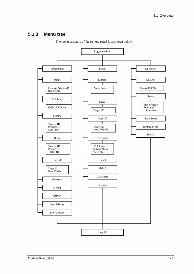
5.1 Overview
C144-E072-01EN 5-7
5.1.3 Menu tree
The menu structure of the remote panel is as shown below:
Login window
Information
Library
Drive
Host I/F
Network
Error History
F/W Version
Target IDHost WWN
Cell Map
Cell/CAS/Drive
Vendor IDProduct IDAuto Clean
Vendor IDProduct IDTarget ID
Status
Library/Adaptor/Drive Status
SNMP
Setup
Library
Auto Clean
Drive
Target ID
Host I/F
Target IDHost WWPN
Network
IP AddressSubnet MaskGateway
Date/Time
SNMP
Operation
CLEAN
Manual CLEAN
Trace
Trace FreezeRelese of
trace freeze
Save Setup
Restore Setup
Logoff
SNMP
Password
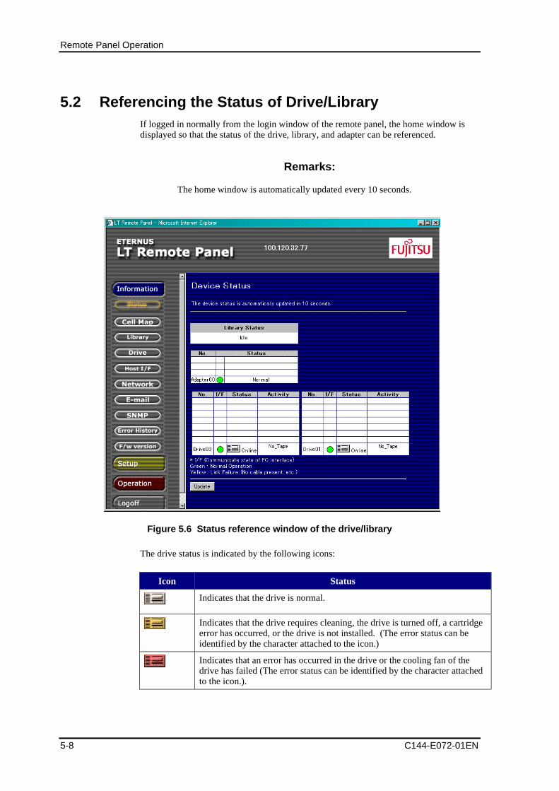
Remote Panel Operation
5-8 C144-E072-01EN
5.2 Referencing the Status of Drive/LibraryIf logged in normally from the login window of the remote panel, the home window isdisplayed so that the status of the drive, library, and adapter can be referenced.
Remarks:
The home window is automatically updated every 10 seconds.
Figure 5.6 Status reference window of the drive/library
The drive status is indicated by the following icons:
Icon Status
Indicates that the drive is normal.
Indicates that the drive requires cleaning, the drive is turned off, a cartridgeerror has occurred, or the drive is not installed. (The error status can beidentified by the character attached to the icon.)
Indicates that an error has occurred in the drive or the cooling fan of thedrive has failed (The error status can be identified by the character attachedto the icon.).
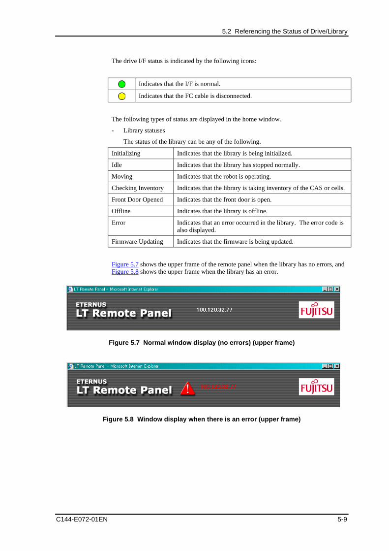
5.2 Referencing the Status of Drive/Library
C144-E072-01EN 5-9
The drive I/F status is indicated by the following icons:
Indicates that the I/F is normal.
Indicates that the FC cable is disconnected.
The following types of status are displayed in the home window.
- Library statuses
The status of the library can be any of the following.
Initializing Indicates that the library is being initialized.
Idle Indicates that the library has stopped normally.
Moving Indicates that the robot is operating.
Checking Inventory Indicates that the library is taking inventory of the CAS or cells.
Front Door Opened Indicates that the front door is open.
Offline Indicates that the library is offline.
Error Indicates that an error occurred in the library. The error code isalso displayed.
Firmware Updating Indicates that the firmware is being updated.
Figure 5.7 shows the upper frame of the remote panel when the library has no errors, andFigure 5.8 shows the upper frame when the library has an error.
Figure 5.7 Normal window display (no errors) (upper frame)
Figure 5.8 Window display when there is an error (upper frame)
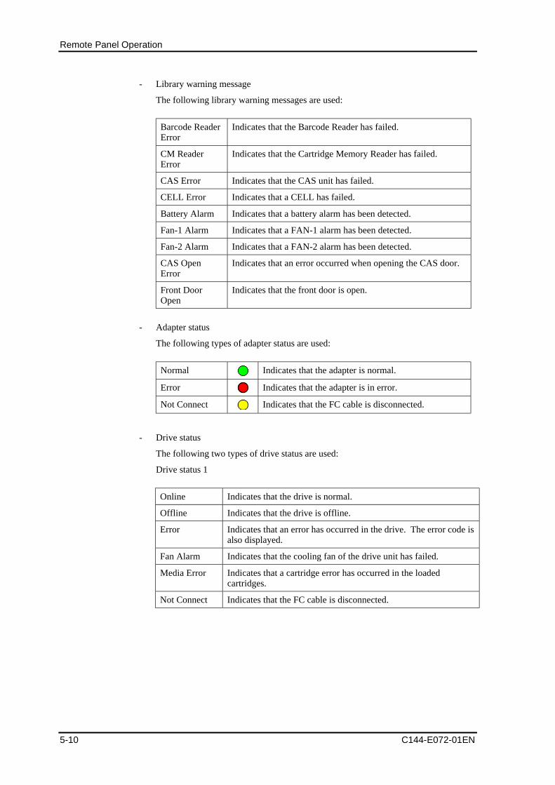
Remote Panel Operation
5-10 C144-E072-01EN
- Library warning message
The following library warning messages are used:
Barcode ReaderError
Indicates that the Barcode Reader has failed.
CM ReaderError
Indicates that the Cartridge Memory Reader has failed.
CAS Error Indicates that the CAS unit has failed.
CELL Error Indicates that a CELL has failed.
Battery Alarm Indicates that a battery alarm has been detected.
Fan-1 Alarm Indicates that a FAN-1 alarm has been detected.
Fan-2 Alarm Indicates that a FAN-2 alarm has been detected.
CAS OpenError
Indicates that an error occurred when opening the CAS door.
Front DoorOpen
Indicates that the front door is open.
- Adapter status
The following types of adapter status are used:
Normal Indicates that the adapter is normal.
Error Indicates that the adapter is in error.
Not Connect Indicates that the FC cable is disconnected.
- Drive status
The following two types of drive status are used:
Drive status 1
Online Indicates that the drive is normal.
Offline Indicates that the drive is offline.
Error Indicates that an error has occurred in the drive. The error code isalso displayed.
Fan Alarm Indicates that the cooling fan of the drive unit has failed.
Media Error Indicates that a cartridge error has occurred in the loadedcartridges.
Not Connect Indicates that the FC cable is disconnected.
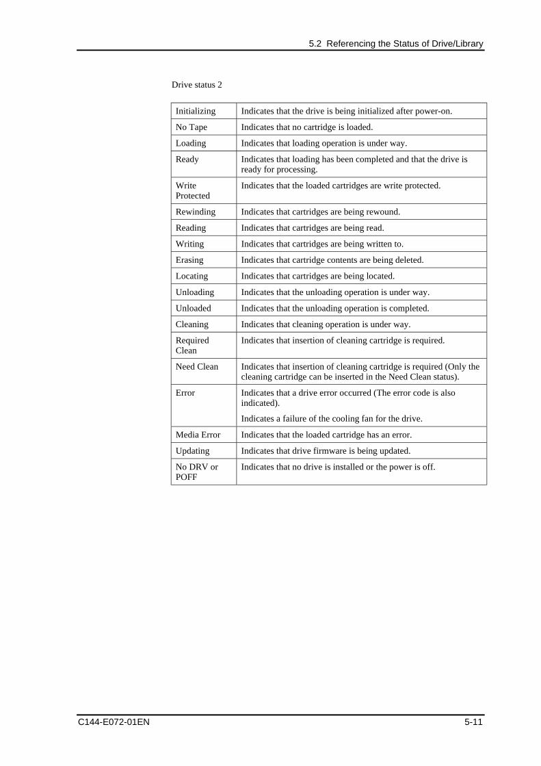
5.2 Referencing the Status of Drive/Library
C144-E072-01EN 5-11
Drive status 2
Initializing Indicates that the drive is being initialized after power-on.
No Tape Indicates that no cartridge is loaded.
Loading Indicates that loading operation is under way.
Ready Indicates that loading has been completed and that the drive isready for processing.
WriteProtected
Indicates that the loaded cartridges are write protected.
Rewinding Indicates that cartridges are being rewound.
Reading Indicates that cartridges are being read.
Writing Indicates that cartridges are being written to.
Erasing Indicates that cartridge contents are being deleted.
Locating Indicates that cartridges are being located.
Unloading Indicates that the unloading operation is under way.
Unloaded Indicates that the unloading operation is completed.
Cleaning Indicates that cleaning operation is under way.
RequiredClean
Indicates that insertion of cleaning cartridge is required.
Need Clean Indicates that insertion of cleaning cartridge is required (Only thecleaning cartridge can be inserted in the Need Clean status).
Error Indicates that a drive error occurred (The error code is alsoindicated).
Indicates a failure of the cooling fan for the drive.
Media Error Indicates that the loaded cartridge has an error.
Updating Indicates that drive firmware is being updated.
No DRV orPOFF
Indicates that no drive is installed or the power is off.
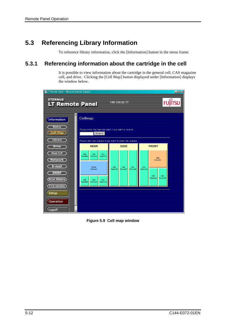
Remote Panel Operation
5-12 C144-E072-01EN
5.3 Referencing Library InformationTo reference library information, click the [Information] button in the menu frame.
5.3.1 Referencing information about the cartridge in the cell
It is possible to view information about the cartridge in the general cell, CAS magazinecell, and drive. Clicking the [Cell Map] button displayed under [Information] displaysthe window below.
Figure 5.9 Cell map window
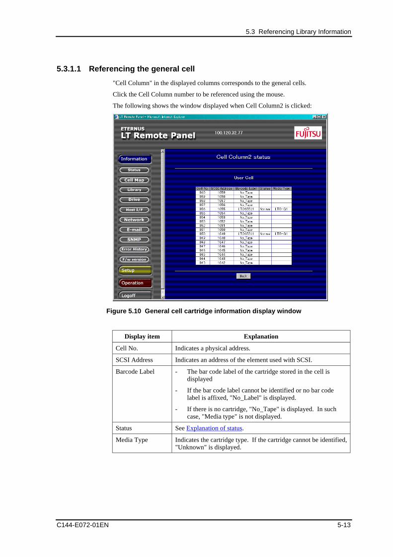
5.3 Referencing Library Information
C144-E072-01EN 5-13
5.3.1.1 Referencing the general cell
"Cell Column" in the displayed columns corresponds to the general cells.
Click the Cell Column number to be referenced using the mouse.
The following shows the window displayed when Cell Column2 is clicked:
Figure 5.10 General cell cartridge information display window
Display item Explanation
Cell No. Indicates a physical address.
SCSI Address Indicates an address of the element used with SCSI.
Barcode Label - The bar code label of the cartridge stored in the cell isdisplayed
- If the bar code label cannot be identified or no bar codelabel is affixed, "No_Label" is displayed.
- If there is no cartridge, "No_Tape" is displayed. In suchcase, "Media type" is not displayed.
Status See Explanation of status.
Media Type Indicates the cartridge type. If the cartridge cannot be identified,"Unknown" is displayed.
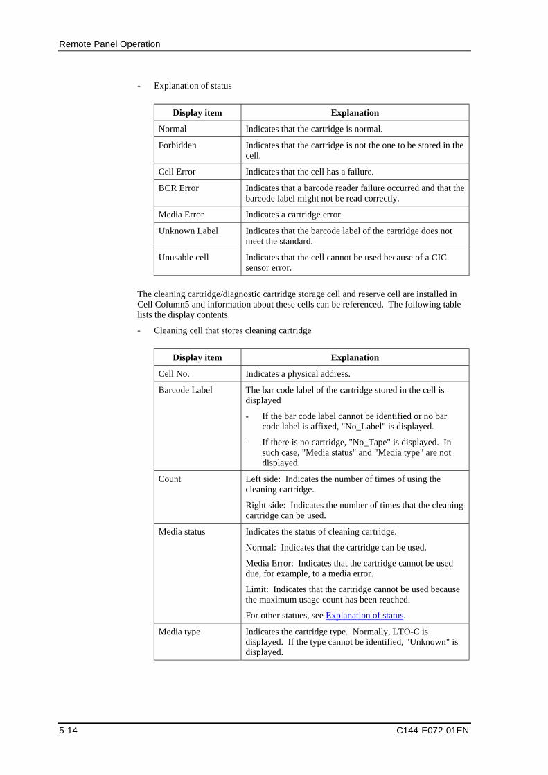
Remote Panel Operation
5-14 C144-E072-01EN
- Explanation of status
Display item Explanation
Normal Indicates that the cartridge is normal.
Forbidden Indicates that the cartridge is not the one to be stored in thecell.
Cell Error Indicates that the cell has a failure.
BCR Error Indicates that a barcode reader failure occurred and that thebarcode label might not be read correctly.
Media Error Indicates a cartridge error.
Unknown Label Indicates that the barcode label of the cartridge does notmeet the standard.
Unusable cell Indicates that the cell cannot be used because of a CICsensor error.
The cleaning cartridge/diagnostic cartridge storage cell and reserve cell are installed inCell Column5 and information about these cells can be referenced. The following tablelists the display contents.
- Cleaning cell that stores cleaning cartridge
Display item Explanation
Cell No. Indicates a physical address.
Barcode Label The bar code label of the cartridge stored in the cell isdisplayed
- If the bar code label cannot be identified or no barcode label is affixed, "No_Label" is displayed.
- If there is no cartridge, "No_Tape" is displayed. Insuch case, "Media status" and "Media type" are notdisplayed.
Count Left side: Indicates the number of times of using thecleaning cartridge.
Right side: Indicates the number of times that the cleaningcartridge can be used.
Media status Indicates the status of cleaning cartridge.
Normal: Indicates that the cartridge can be used.
Media Error: Indicates that the cartridge cannot be useddue, for example, to a media error.
Limit: Indicates that the cartridge cannot be used becausethe maximum usage count has been reached.
For other statues, see Explanation of status.
Media type Indicates the cartridge type. Normally, LTO-C isdisplayed. If the type cannot be identified, "Unknown" isdisplayed.
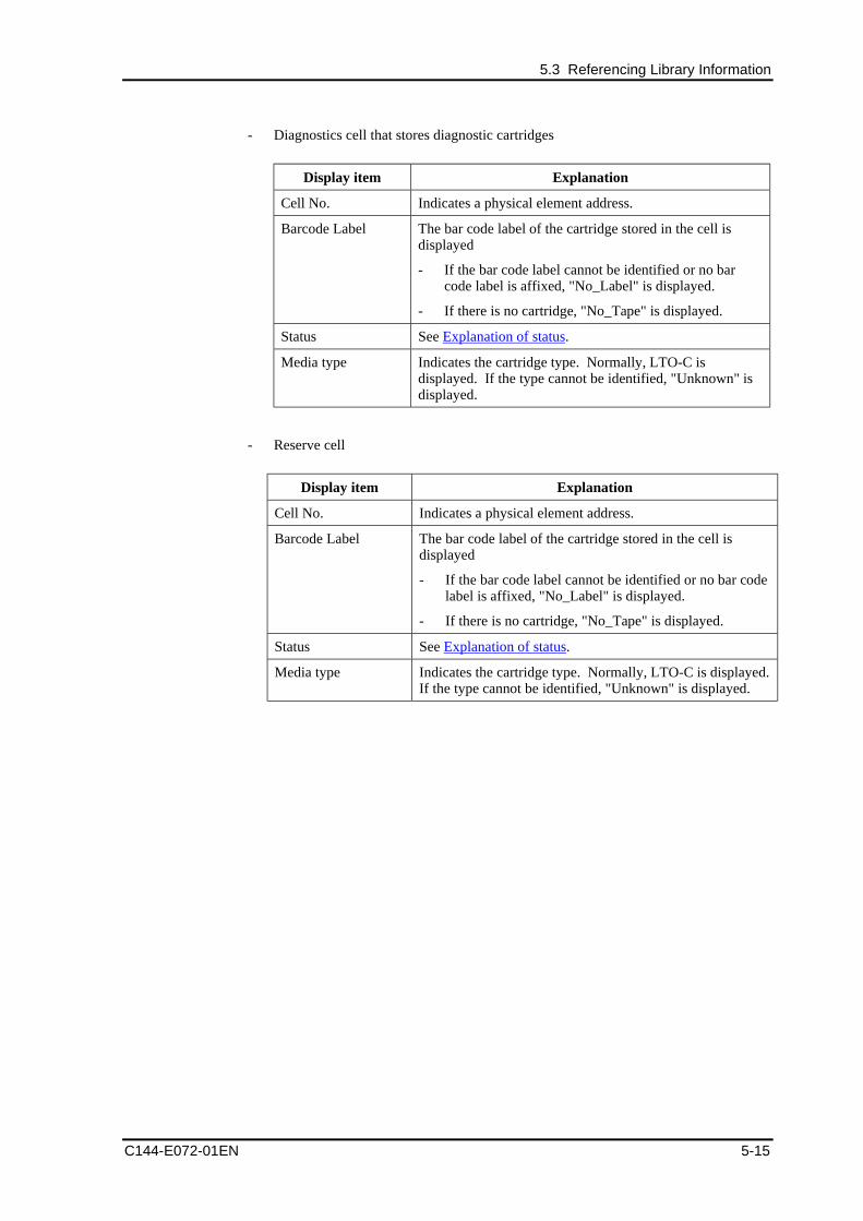
5.3 Referencing Library Information
C144-E072-01EN 5-15
- Diagnostics cell that stores diagnostic cartridges
Display item Explanation
Cell No. Indicates a physical element address.
Barcode Label The bar code label of the cartridge stored in the cell isdisplayed
- If the bar code label cannot be identified or no barcode label is affixed, "No_Label" is displayed.
- If there is no cartridge, "No_Tape" is displayed.
Status See Explanation of status.
Media type Indicates the cartridge type. Normally, LTO-C isdisplayed. If the type cannot be identified, "Unknown" isdisplayed.
- Reserve cell
Display item Explanation
Cell No. Indicates a physical element address.
Barcode Label The bar code label of the cartridge stored in the cell isdisplayed
- If the bar code label cannot be identified or no bar codelabel is affixed, "No_Label" is displayed.
- If there is no cartridge, "No_Tape" is displayed.
Status See Explanation of status.
Media type Indicates the cartridge type. Normally, LTO-C is displayed.If the type cannot be identified, "Unknown" is displayed.
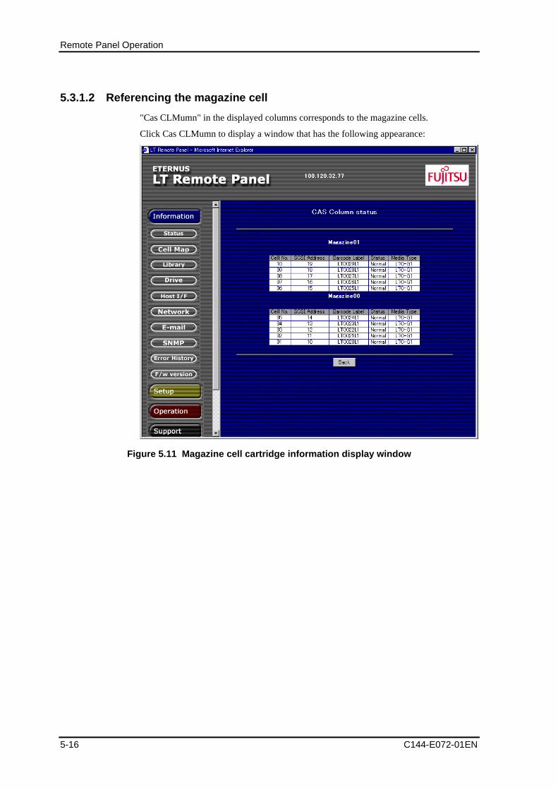
Remote Panel Operation
5-16 C144-E072-01EN
5.3.1.2 Referencing the magazine cell
"Cas CLMumn" in the displayed columns corresponds to the magazine cells.
Click Cas CLMumn to display a window that has the following appearance:
Figure 5.11 Magazine cell cartridge information display window
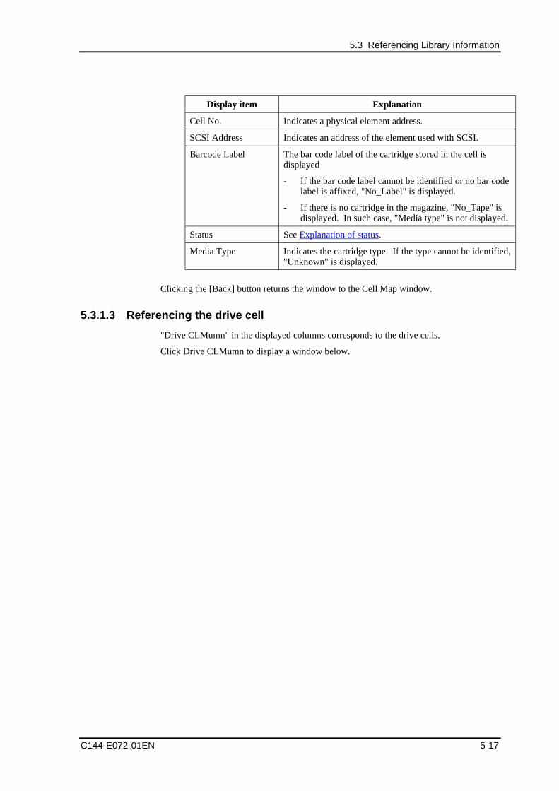
5.3 Referencing Library Information
C144-E072-01EN 5-17
Display item Explanation
Cell No. Indicates a physical element address.
SCSI Address Indicates an address of the element used with SCSI.
Barcode Label The bar code label of the cartridge stored in the cell isdisplayed
- If the bar code label cannot be identified or no bar codelabel is affixed, "No_Label" is displayed.
- If there is no cartridge in the magazine, "No_Tape" isdisplayed. In such case, "Media type" is not displayed.
Status See Explanation of status.
Media Type Indicates the cartridge type. If the type cannot be identified,"Unknown" is displayed.
Clicking the [Back] button returns the window to the Cell Map window.
5.3.1.3 Referencing the drive cell
"Drive CLMumn" in the displayed columns corresponds to the drive cells.
Click Drive CLMumn to display a window below.
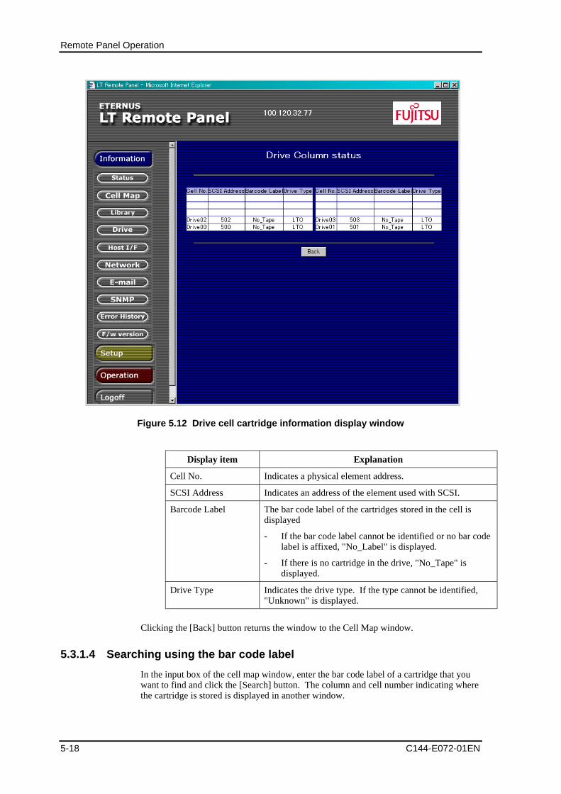
Remote Panel Operation
5-18 C144-E072-01EN
Figure 5.12 Drive cell cartridge information display window
Display item Explanation
Cell No. Indicates a physical element address.
SCSI Address Indicates an address of the element used with SCSI.
Barcode Label The bar code label of the cartridges stored in the cell isdisplayed
- If the bar code label cannot be identified or no bar codelabel is affixed, "No_Label" is displayed.
- If there is no cartridge in the drive, "No_Tape" isdisplayed.
Drive Type Indicates the drive type. If the type cannot be identified,"Unknown" is displayed.
Clicking the [Back] button returns the window to the Cell Map window.
5.3.1.4 Searching using the bar code label
In the input box of the cell map window, enter the bar code label of a cartridge that youwant to find and click the [Search] button. The column and cell number indicating wherethe cartridge is stored is displayed in another window.
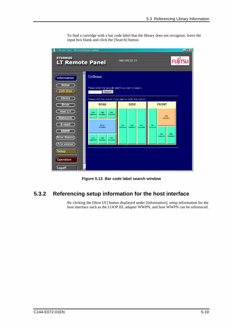
5.3 Referencing Library Information
C144-E072-01EN 5-19
To find a cartridge with a bar code label that the library does not recognize, leave theinput box blank and click the [Search] button.
Figure 5.13 Bar code label search window
5.3.2 Referencing setup information for the host interface
By clicking the [Host I/F] button displayed under [Information], setup information for thehost interface such as the LOOP ID, adapter WWPN, and host WWPN can be referenced.
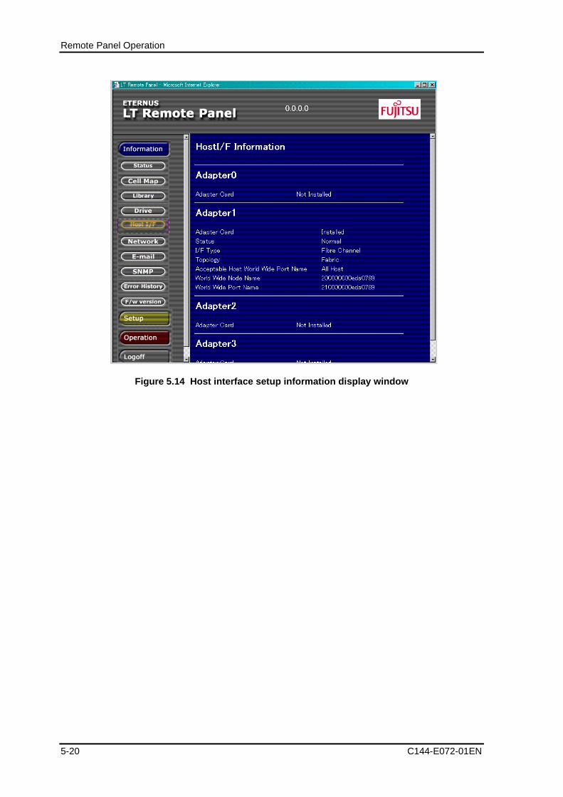
Remote Panel Operation
5-20 C144-E072-01EN
Figure 5.14 Host interface setup information display window
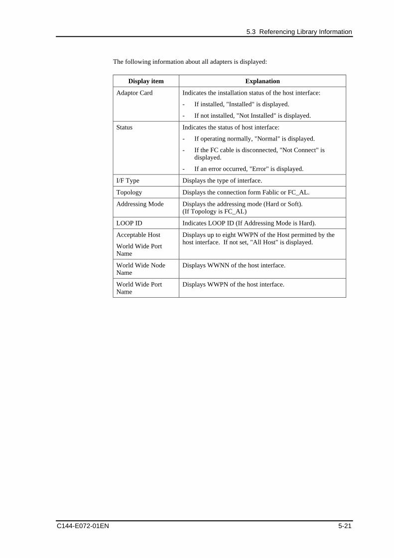
5.3 Referencing Library Information
C144-E072-01EN 5-21
The following information about all adapters is displayed:
Display item Explanation
Adaptor Card Indicates the installation status of the host interface:
- If installed, "Installed" is displayed.
- If not installed, "Not Installed" is displayed.
Status Indicates the status of host interface:
- If operating normally, "Normal" is displayed.
- If the FC cable is disconnected, "Not Connect" isdisplayed.
- If an error occurred, "Error" is displayed.
I/F Type Displays the type of interface.
Topology Displays the connection form Fablic or FC_AL.
Addressing Mode Displays the addressing mode (Hard or Soft).(If Topology is FC_AL)
LOOP ID Indicates LOOP ID (If Addressing Mode is Hard).
Acceptable Host
World Wide PortName
Displays up to eight WWPN of the Host permitted by thehost interface. If not set, "All Host" is displayed.
World Wide NodeName
Displays WWNN of the host interface.
World Wide PortName
Displays WWPN of the host interface.
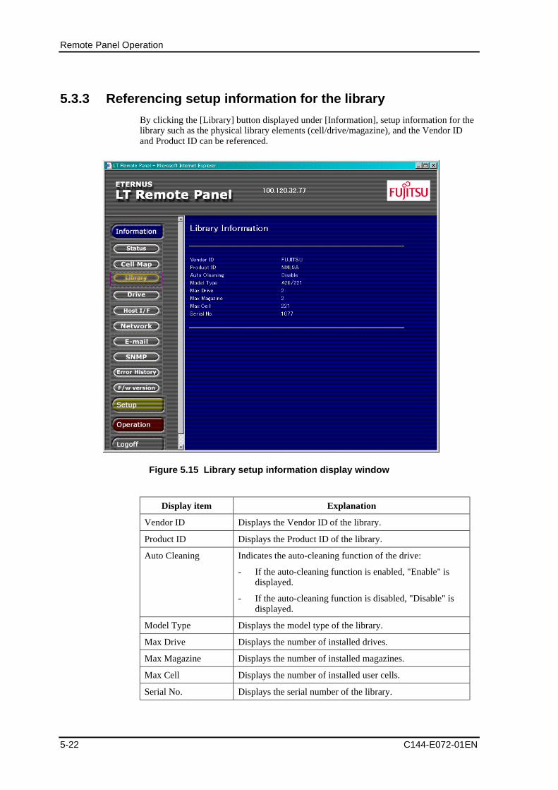
Remote Panel Operation
5-22 C144-E072-01EN
5.3.3 Referencing setup information for the library
By clicking the [Library] button displayed under [Information], setup information for thelibrary such as the physical library elements (cell/drive/magazine), and the Vendor IDand Product ID can be referenced.
Figure 5.15 Library setup information display window
Display item Explanation
Vendor ID Displays the Vendor ID of the library.
Product ID Displays the Product ID of the library.
Auto Cleaning Indicates the auto-cleaning function of the drive:
- If the auto-cleaning function is enabled, "Enable" isdisplayed.
- If the auto-cleaning function is disabled, "Disable" isdisplayed.
Model Type Displays the model type of the library.
Max Drive Displays the number of installed drives.
Max Magazine Displays the number of installed magazines.
Max Cell Displays the number of installed user cells.
Serial No. Displays the serial number of the library.
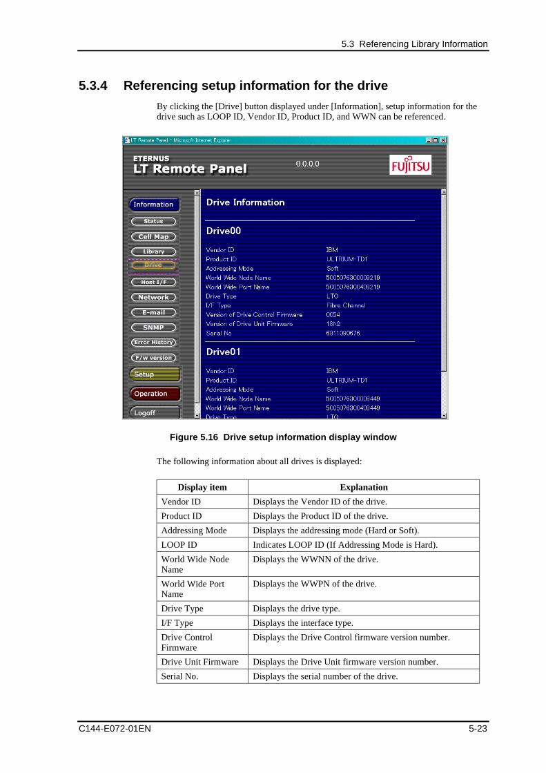
5.3 Referencing Library Information
C144-E072-01EN 5-23
5.3.4 Referencing setup information for the drive
By clicking the [Drive] button displayed under [Information], setup information for thedrive such as LOOP ID, Vendor ID, Product ID, and WWN can be referenced.
Figure 5.16 Drive setup information display window
The following information about all drives is displayed:
Display item Explanation
Vendor ID Displays the Vendor ID of the drive.
Product ID Displays the Product ID of the drive.
Addressing Mode Displays the addressing mode (Hard or Soft).
LOOP ID Indicates LOOP ID (If Addressing Mode is Hard).
World Wide NodeName
Displays the WWNN of the drive.
World Wide PortName
Displays the WWPN of the drive.
Drive Type Displays the drive type.
I/F Type Displays the interface type.
Drive ControlFirmware
Displays the Drive Control firmware version number.
Drive Unit Firmware Displays the Drive Unit firmware version number.
Serial No. Displays the serial number of the drive.
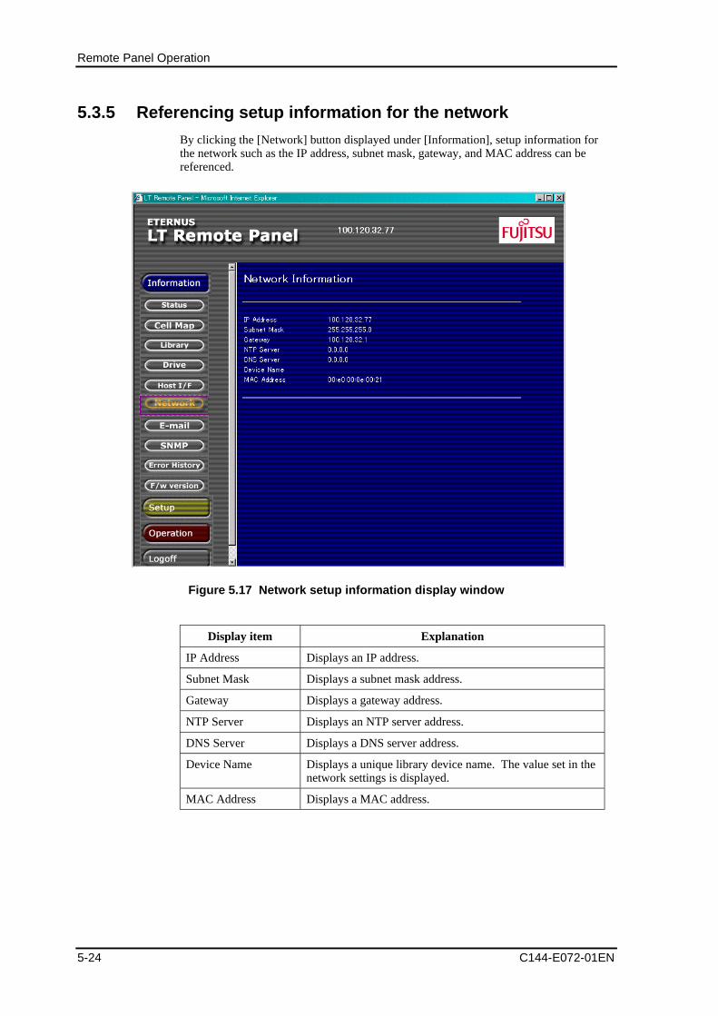
Remote Panel Operation
5-24 C144-E072-01EN
5.3.5 Referencing setup information for the network
By clicking the [Network] button displayed under [Information], setup information forthe network such as the IP address, subnet mask, gateway, and MAC address can bereferenced.
Figure 5.17 Network setup information display window
Display item Explanation
IP Address Displays an IP address.
Subnet Mask Displays a subnet mask address.
Gateway Displays a gateway address.
NTP Server Displays an NTP server address.
DNS Server Displays a DNS server address.
Device Name Displays a unique library device name. The value set in thenetwork settings is displayed.
MAC Address Displays a MAC address.
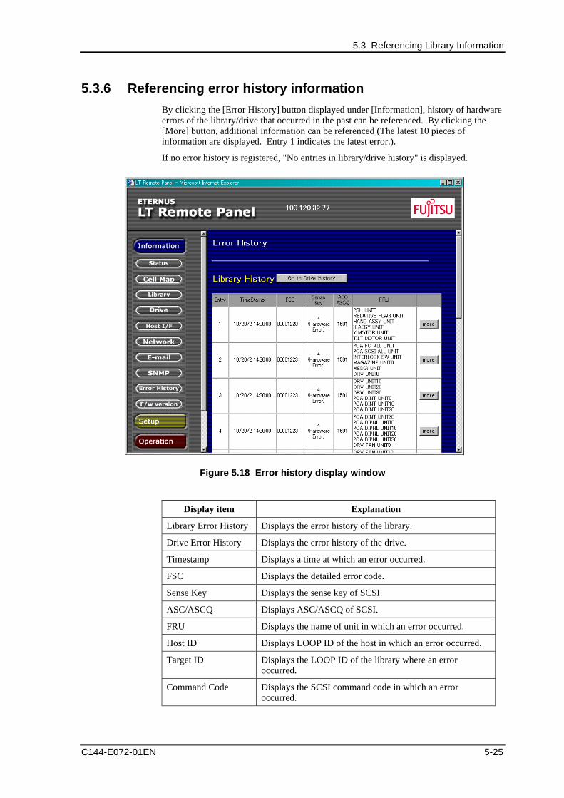
5.3 Referencing Library Information
C144-E072-01EN 5-25
5.3.6 Referencing error history information
By clicking the [Error History] button displayed under [Information], history of hardwareerrors of the library/drive that occurred in the past can be referenced. By clicking the[More] button, additional information can be referenced (The latest 10 pieces ofinformation are displayed. Entry 1 indicates the latest error.).
If no error history is registered, "No entries in library/drive history" is displayed.
Figure 5.18 Error history display window
Display item Explanation
Library Error History Displays the error history of the library.
Drive Error History Displays the error history of the drive.
Timestamp Displays a time at which an error occurred.
FSC Displays the detailed error code.
Sense Key Displays the sense key of SCSI.
ASC/ASCQ Displays ASC/ASCQ of SCSI.
FRU Displays the name of unit in which an error occurred.
Host ID Displays LOOP ID of the host in which an error occurred.
Target ID Displays the LOOP ID of the library where an erroroccurred.
Command Code Displays the SCSI command code in which an erroroccurred.
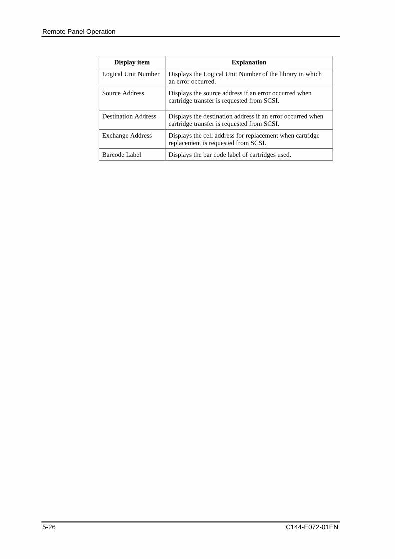
Remote Panel Operation
5-26 C144-E072-01EN
Display item Explanation
Logical Unit Number Displays the Logical Unit Number of the library in whichan error occurred.
Source Address Displays the source address if an error occurred whencartridge transfer is requested from SCSI.
Destination Address Displays the destination address if an error occurred whencartridge transfer is requested from SCSI.
Exchange Address Displays the cell address for replacement when cartridgereplacement is requested from SCSI.
Barcode Label Displays the bar code label of cartridges used.
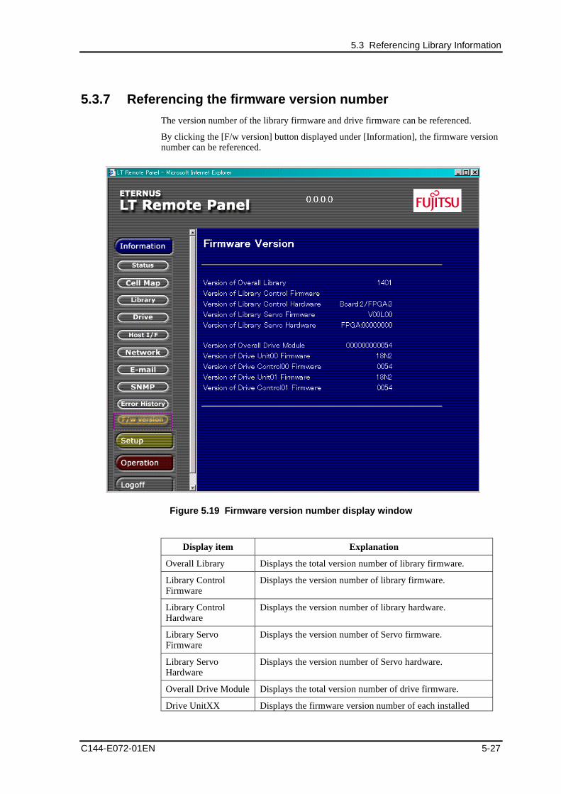
5.3 Referencing Library Information
C144-E072-01EN 5-27
5.3.7 Referencing the firmware version number
The version number of the library firmware and drive firmware can be referenced.
By clicking the [F/w version] button displayed under [Information], the firmware versionnumber can be referenced.
Figure 5.19 Firmware version number display window
Display item Explanation
Overall Library Displays the total version number of library firmware.
Library ControlFirmware
Displays the version number of library firmware.
Library ControlHardware
Displays the version number of library hardware.
Library ServoFirmware
Displays the version number of Servo firmware.
Library ServoHardware
Displays the version number of Servo hardware.
Overall Drive Module Displays the total version number of drive firmware.
Drive UnitXX Displays the firmware version number of each installed
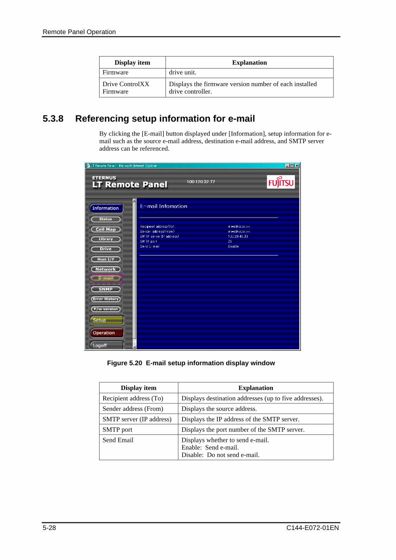
Remote Panel Operation
5-28 C144-E072-01EN
Display item Explanation
Firmware drive unit.
Drive ControlXXFirmware
Displays the firmware version number of each installeddrive controller.
5.3.8 Referencing setup information for e-mail
By clicking the [E-mail] button displayed under [Information], setup information for e-mail such as the source e-mail address, destination e-mail address, and SMTP serveraddress can be referenced.
Figure 5.20 E-mail setup information display window
Display item Explanation
Recipient address (To) Displays destination addresses (up to five addresses).
Sender address (From) Displays the source address.
SMTP server (IP address) Displays the IP address of the SMTP server.
SMTP port Displays the port number of the SMTP server.
Send Email Displays whether to send e-mail.Enable: Send e-mail.Disable: Do not send e-mail.
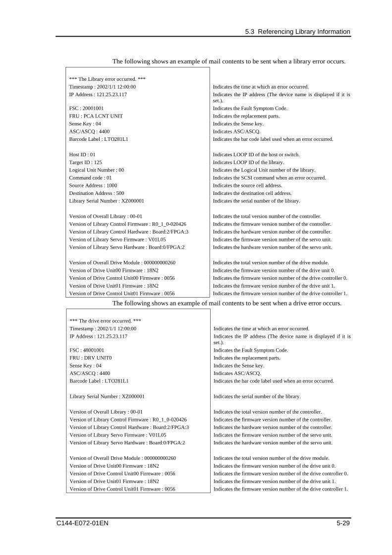
5.3 Referencing Library Information
C144-E072-01EN 5-29
The following shows an example of mail contents to be sent when a library error occurs.
*** The Library error occurred. ***
Timestamp : 2002/1/1 12:00:00 Indicates the time at which an error occurred.
IP Address : 121.25.23.117 Indicates the IP address (The device name is displayed if it isset.).
FSC : 20001001 Indicates the Fault Symptom Code.
FRU : PCA LCNT UNIT Indicates the replacement parts.
Sense Key : 04 Indicates the Sense key.
ASC/ASCQ : 4400 Indicates ASC/ASCQ.
Barcode Label : LTO281L1 Indicates the bar code label used when an error occurred.
Host ID : 01 Indicates LOOP ID of the host or switch.
Target ID : 125 Indicates LOOP ID of the library.
Logical Unit Number : 00 Indicates the Logical Unit number of the library.
Command code : 01 Indicates the SCSI command when an error occurred.
Source Address : 1000 Indicates the source cell address.
Destination Address : 500 Indicates the destination cell address.
Library Serial Number : XZ000001 Indicates the serial number of the library.
Version of Overall Library : 00-01 Indicates the total version number of the controller.
Version of Library Control Firmware : R0_1_0-020426 Indicates the firmware version number of the controller.
Version of Library Control Hardware : Board:2/FPGA:3 Indicates the hardware version number of the controller.
Version of Library Servo Firmware : V01L05 Indicates the firmware version number of the servo unit.
Version of Library Servo Hardware : Board:0/FPGA:2 Indicates the hardware version number of the servo unit.
Version of Overall Drive Module : 000000000260 Indicates the total version number of the drive module.
Version of Drive Unit00 Firmware : 18N2 Indicates the firmware version number of the drive unit 0.
Version of Drive Control Unit00 Firmware : 0056 Indicates the firmware version number of the drive controller 0.
Version of Drive Unit01 Firmware : 18N2 Indicates the firmware version number of the drive unit 1.
Version of Drive Control Unit01 Firmware : 0056 Indicates the firmware version number of the drive controller 1.
The following shows an example of mail contents to be sent when a drive error occurs.
*** The drive error occurred. ***
Timestamp : 2002/1/1 12:00:00 Indicates the time at which an error occurred.
IP Address : 121.25.23.117 Indicates the IP address (The device name is displayed if it isset.).
FSC : 48001001 Indicates the Fault Symptom Code.
FRU : DRV UNIT0 Indicates the replacement parts.
Sense Key : 04 Indicates the Sense key.
ASC/ASCQ : 4400 Indicates ASC/ASCQ.
Barcode Label : LTO281L1 Indicates the bar code label used when an error occurred.
Library Serial Number : XZ000001 Indicates the serial number of the library.
Version of Overall Library : 00-01 Indicates the total version number of the controller.
Version of Library Control Firmware : R0_1_0-020426 Indicates the firmware version number of the controller.
Version of Library Control Hardware : Board:2/FPGA:3 Indicates the hardware version number of the controller.
Version of Library Servo Firmware : V01L05 Indicates the firmware version number of the servo unit.
Version of Library Servo Hardware : Board:0/FPGA:2 Indicates the hardware version number of the servo unit.
Version of Overall Drive Module : 000000000260 Indicates the total version number of the drive module.
Version of Drive Unit00 Firmware : 18N2 Indicates the firmware version number of the drive unit 0.
Version of Drive Control Unit00 Firmware : 0056 Indicates the firmware version number of the drive controller 0.
Version of Drive Unit01 Firmware : 18N2 Indicates the firmware version number of the drive unit 1.
Version of Drive Control Unit01 Firmware : 0056 Indicates the firmware version number of the drive controller 1.
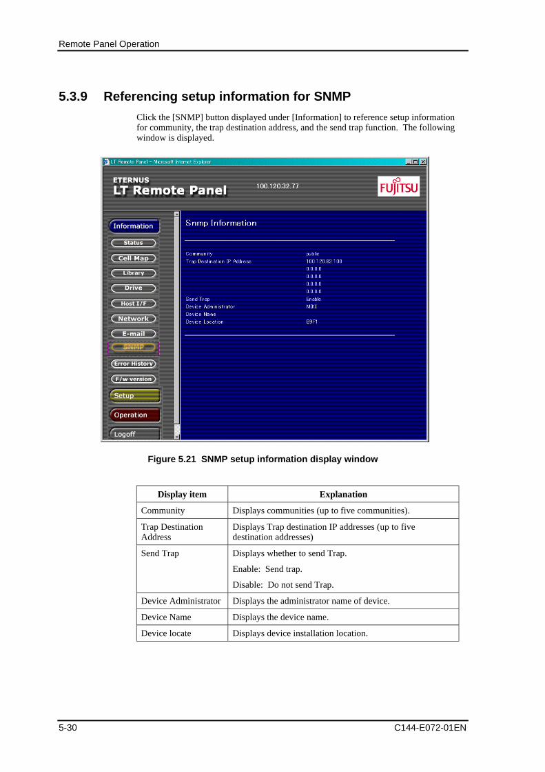
Remote Panel Operation
5-30 C144-E072-01EN
5.3.9 Referencing setup information for SNMP
Click the [SNMP] button displayed under [Information] to reference setup informationfor community, the trap destination address, and the send trap function. The followingwindow is displayed.
Figure 5.21 SNMP setup information display window
Display item Explanation
Community Displays communities (up to five communities).
Trap DestinationAddress
Displays Trap destination IP addresses (up to fivedestination addresses)
Send Trap Displays whether to send Trap.
Enable: Send trap.
Disable: Do not send Trap.
Device Administrator Displays the administrator name of device.
Device Name Displays the device name.
Device locate Displays device installation location.
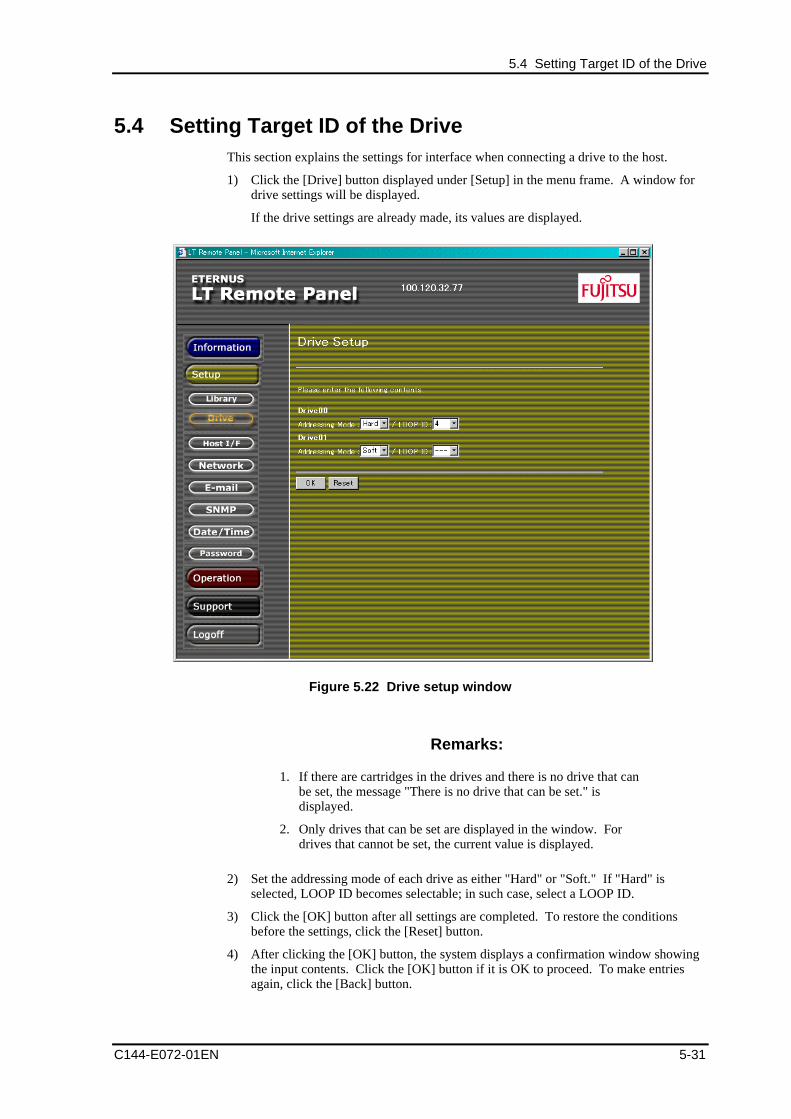
5.4 Setting Target ID of the Drive
C144-E072-01EN 5-31
5.4 Setting Target ID of the DriveThis section explains the settings for interface when connecting a drive to the host.
1) Click the [Drive] button displayed under [Setup] in the menu frame. A window fordrive settings will be displayed.
If the drive settings are already made, its values are displayed.
Figure 5.22 Drive setup window
Remarks:
1. If there are cartridges in the drives and there is no drive that canbe set, the message "There is no drive that can be set." isdisplayed.
2. Only drives that can be set are displayed in the window. Fordrives that cannot be set, the current value is displayed.
2) Set the addressing mode of each drive as either "Hard" or "Soft." If "Hard" isselected, LOOP ID becomes selectable; in such case, select a LOOP ID.
3) Click the [OK] button after all settings are completed. To restore the conditionsbefore the settings, click the [Reset] button.
4) After clicking the [OK] button, the system displays a confirmation window showingthe input contents. Click the [OK] button if it is OK to proceed. To make entriesagain, click the [Back] button.
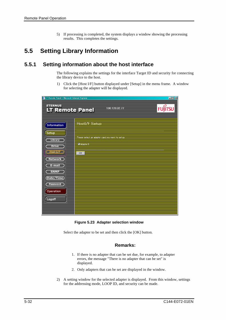
Remote Panel Operation
5-32 C144-E072-01EN
5) If processing is completed, the system displays a window showing the processingresults. This completes the settings.
5.5 Setting Library Information
5.5.1 Setting information about the host interface
The following explains the settings for the interface Target ID and security for connectingthe library device to the host.
1) Click the [Host I/F] button displayed under [Setup] in the menu frame. A windowfor selecting the adapter will be displayed.
Figure 5.23 Adapter selection window
Select the adapter to be set and then click the [OK] button.
Remarks:
1. If there is no adapter that can be set due, for example, to adaptererrors, the message "There is no adapter that can be set" isdisplayed.
2. Only adapters that can be set are displayed in the window.
2) A setting window for the selected adapter is displayed. From this window, settingsfor the addressing mode, LOOP ID, and security can be made.

5.5 Setting Library Information
C144-E072-01EN 5-33
Figure 5.24 Host interface setting window
3) Make settings for each item.
- Topology: Select from "Fablic" or "FC_AL".
- Addressing Mode: This item is enabled if FC_AL is selected in Topology.Select from "Hard" and "Soft."
- LOOP ID: This item needs to be specified if "Hard" is set as the AddressingMode.
- Acceptable Host World Wide Port Name: Enter the WWPN of the host that ispermitted to access the setup adapter. Up to eight port names can be entered. Inone text area, up to 16 characters can be entered. Only en-size alphanumericcharacters can be entered. If any character other than alphanumeric characters isentered, an input error message is displayed.
4) Click the [OK] button after all settings are completed. To restore the conditionsbefore the settings, click the [Reset] button.
5) After clicking the [OK] button, the system displays a confirmation window showingthe input contents. Click the [OK] button if it is OK to proceed. To make entriesagain, click the [Back] button.
6) If processing is completed, the system displays a window showing the processingresults. To continue settings of the host interface, repeat the above procedure startingwith 1).
7) The values that have been set are enabled after settings are completed and the deviceis restarted.
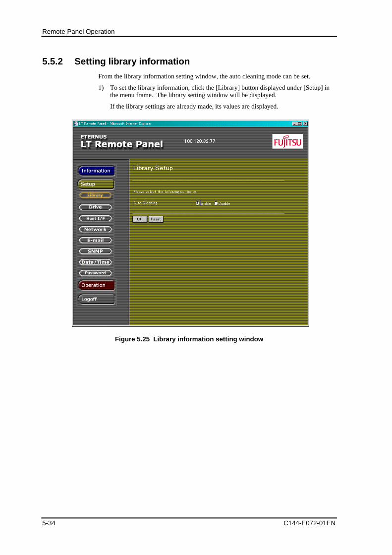
Remote Panel Operation
5-34 C144-E072-01EN
5.5.2 Setting library information
From the library information setting window, the auto cleaning mode can be set.
1) To set the library information, click the [Library] button displayed under [Setup] inthe menu frame. The library setting window will be displayed.
If the library settings are already made, its values are displayed.
Figure 5.25 Library information setting window
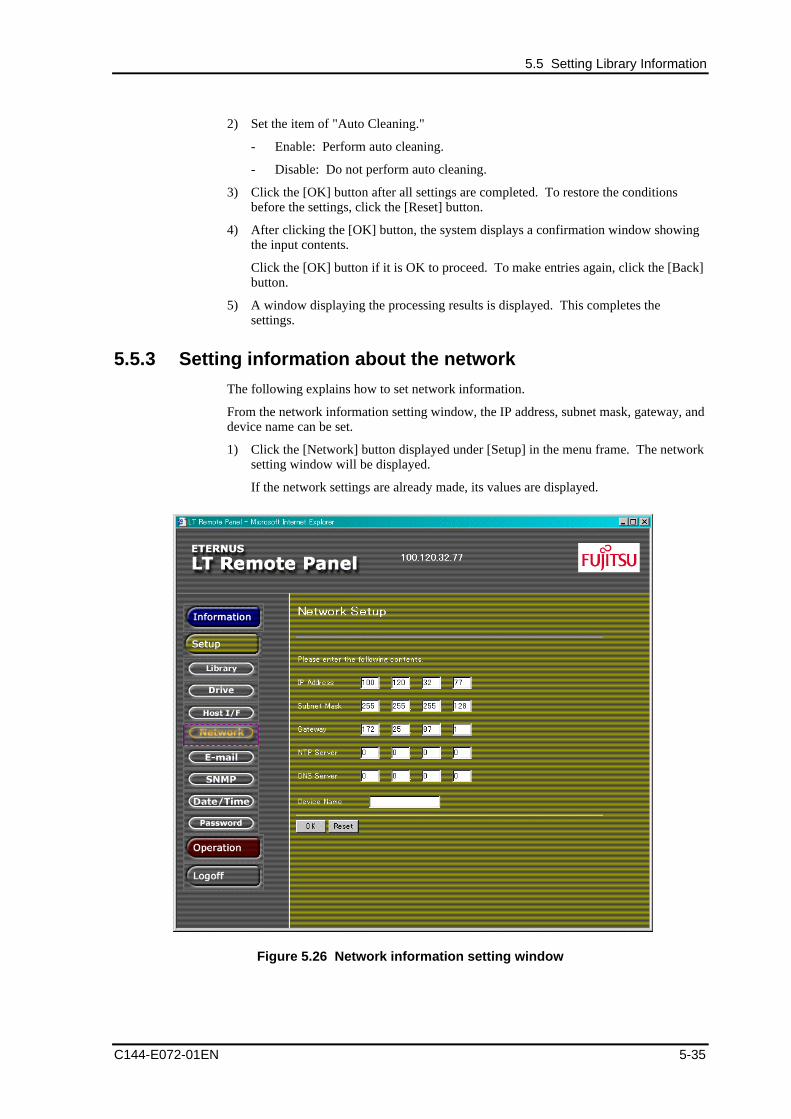
5.5 Setting Library Information
C144-E072-01EN 5-35
2) Set the item of "Auto Cleaning."
- Enable: Perform auto cleaning.
- Disable: Do not perform auto cleaning.
3) Click the [OK] button after all settings are completed. To restore the conditionsbefore the settings, click the [Reset] button.
4) After clicking the [OK] button, the system displays a confirmation window showingthe input contents.
Click the [OK] button if it is OK to proceed. To make entries again, click the [Back]button.
5) A window displaying the processing results is displayed. This completes thesettings.
5.5.3 Setting information about the network
The following explains how to set network information.
From the network information setting window, the IP address, subnet mask, gateway, anddevice name can be set.
1) Click the [Network] button displayed under [Setup] in the menu frame. The networksetting window will be displayed.
If the network settings are already made, its values are displayed.
Figure 5.26 Network information setting window
Remote Panel Operation
5-36 C144-E072-01EN
2) Set each of the following items:
- IP Address <required>: Enter the IP address of this library. Only en-sizenumeric characters can be entered.
- Subnet Mask <required>: Enter the subnet mask of this library. Only en-sizenumeric characters can be entered.
- Gateway: This item needs to be set if accessed from outside SUB-LAN oraccessed from the browser via a proxy server inside SUB-LAN. Only en-sizenumeric characters can be entered.
- NTP Server: Enter the IP address of the NTP server required to set the clockfrom the NTP Server. Only en-size numeric characters can be entered.
- DNS Server: Enter the IP address of the DNS server required for remotesupport. Only en-size numeric characters can be entered.
- Device Name: Enter a unique device name to represent on the browser.
If not set, the IP address is displayed. Though normallydisplayed in white, the color changes to red when an erroroccurs in the library. Up to 20 characters can be entered in thetext area. Characters that can be entered are en-sizealphanumeric characters, blank characters, and en-sizesymbols (!"#$%&'()*+'-./:;<=>?@[\]^_`{|}).
Remarks:
1. If a character that is not allowed or an out-of-range value isentered, an input error message is displayed.
2. To enable the settings of the IP address, subnet mask, gateway,NTP server, and DNS server, the library device needs to berestarted.
5.5.4 Setting the clock
The following explains how to set the date and time for the library device.
1) Click the [Date/Time] button displayed under [Setup] in the menu frame to displaythe date/time setting window.
If the date/time are already set, their values are displayed.
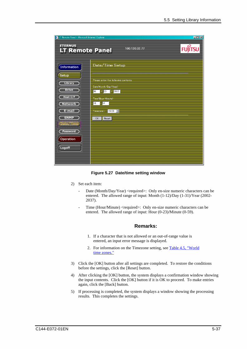
5.5 Setting Library Information
C144-E072-01EN 5-37
Figure 5.27 Date/time setting window
2) Set each item:
- Date (Month/Day/Year) <required>: Only en-size numeric characters can beentered. The allowed range of input: Month (1-12)/Day (1-31)/Year (2002-2037).
- Time (Hour/Minute) <required>: Only en-size numeric characters can beentered. The allowed range of input: Hour (0-23)/Minute (0-59).
Remarks:
1. If a character that is not allowed or an out-of-range value isentered, an input error message is displayed.
2. For information on the Timezone setting, see Table 4.5, "Worldtime zones."
3) Click the [OK] button after all settings are completed. To restore the conditionsbefore the settings, click the [Reset] button.
4) After clicking the [OK] button, the system displays a confirmation window showingthe input contents. Click the [OK] button if it is OK to proceed. To make entriesagain, click the [Back] button.
5) If processing is completed, the system displays a window showing the processingresults. This completes the settings.
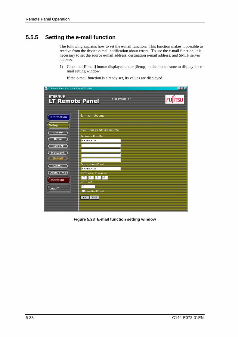
Remote Panel Operation
5-38 C144-E072-01EN
5.5.5 Setting the e-mail function
The following explains how to set the e-mail function. This function makes it possible toreceive from the device e-mail notification about errors. To use the e-mail function, it isnecessary to set the source e-mail address, destination e-mail address, and SMTP serveraddress.
1) Click the [E-mail] button displayed under [Setup] in the menu frame to display the e-mail setting window.
If the e-mail function is already set, its values are displayed.
Figure 5.28 E-mail function setting window
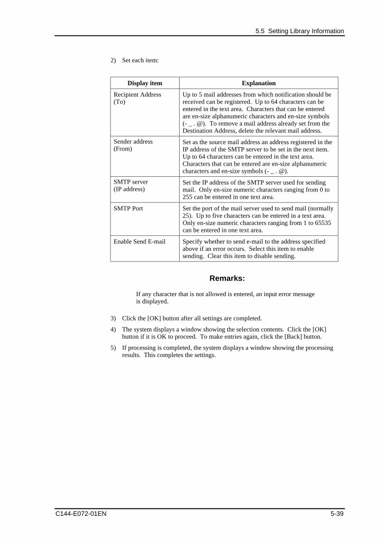
5.5 Setting Library Information
C144-E072-01EN 5-39
2) Set each item:
Display item Explanation
Recipient Address(To)
Up to 5 mail addresses from which notification should bereceived can be registered. Up to 64 characters can beentered in the text area. Characters that can be enteredare en-size alphanumeric characters and en-size symbols(- _ . @). To remove a mail address already set from theDestination Address, delete the relevant mail address.
Sender address(From)
Set as the source mail address an address registered in theIP address of the SMTP server to be set in the next item.Up to 64 characters can be entered in the text area.Characters that can be entered are en-size alphanumericcharacters and en-size symbols (- _ . @).
SMTP server(IP address)
Set the IP address of the SMTP server used for sendingmail. Only en-size numeric characters ranging from 0 to255 can be entered in one text area.
SMTP Port Set the port of the mail server used to send mail (normally25). Up to five characters can be entered in a text area.Only en-size numeric characters ranging from 1 to 65535can be entered in one text area.
Enable Send E-mail Specify whether to send e-mail to the address specifiedabove if an error occurs. Select this item to enablesending. Clear this item to disable sending.
Remarks:
If any character that is not allowed is entered, an input error messageis displayed.
3) Click the [OK] button after all settings are completed.
4) The system displays a window showing the selection contents. Click the [OK]button if it is OK to proceed. To make entries again, click the [Back] button.
5) If processing is completed, the system displays a window showing the processingresults. This completes the settings.
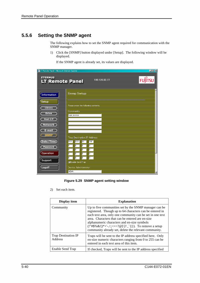
Remote Panel Operation
5-40 C144-E072-01EN
5.5.6 Setting the SNMP agent
The following explains how to set the SNMP agent required for communication with theSNMP manager.
1) Click the [SNMP] button displayed under [Setup]. The following window will bedisplayed.
If the SNMP agent is already set, its values are displayed.
Figure 5.29 SNMP agent setting window
2) Set each item.
Display item Explanation
Community Up to five communities set by the SNMP manager can beregistered. Though up to 64 characters can be entered ineach text area, only one community can be set in one textarea. Characters that can be entered are en-sizealphanumeric characters and en-size symbols(!"#$%&'()*+'-./:;<=>?@[\]^_`{|}). To remove a setupcommunity already set, delete the relevant community.
Trap Destination IPAddress
Traps will be sent to the IP address specified here. Onlyen-size numeric characters ranging from 0 to 255 can beentered in each text area of this item.
Enable Send Trap If checked, Traps will be sent to the IP address specified
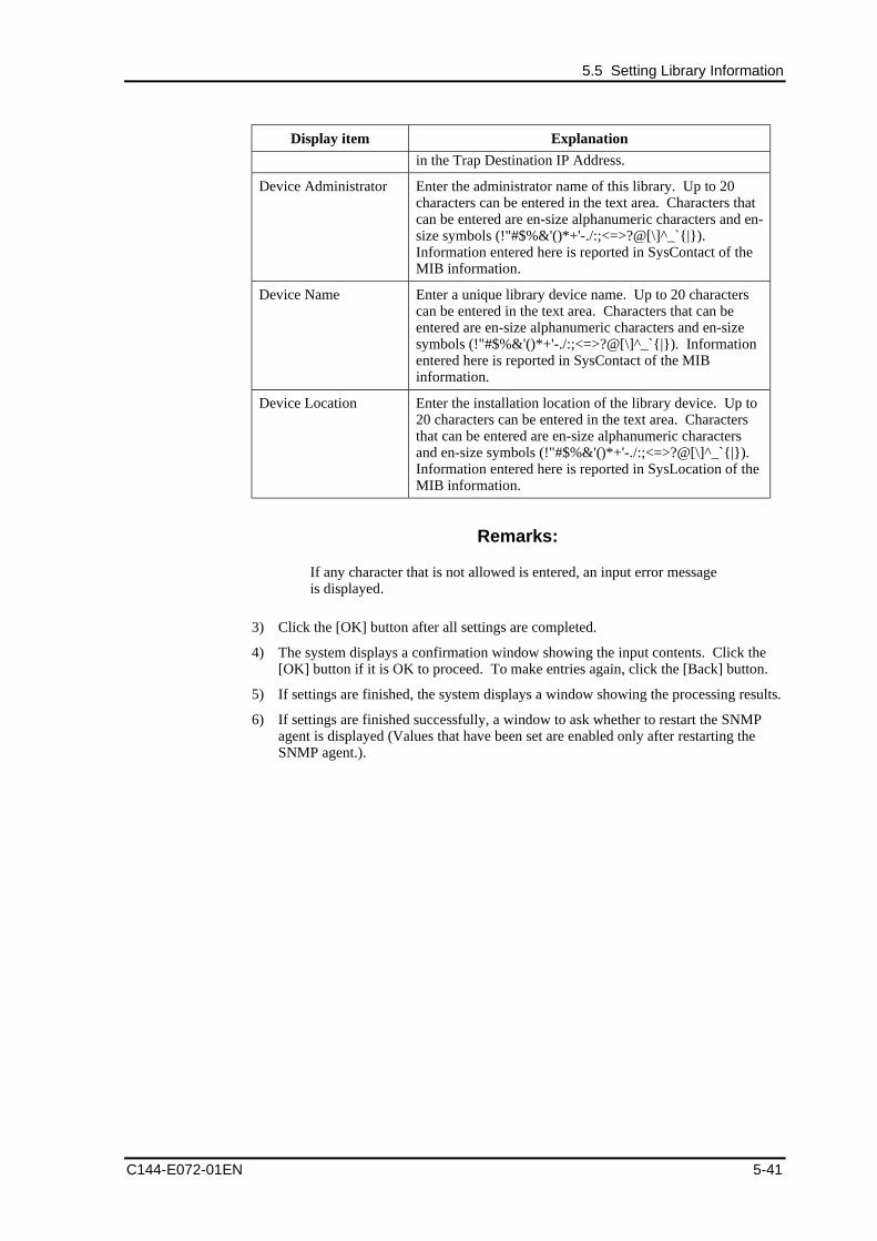
5.5 Setting Library Information
C144-E072-01EN 5-41
Display item Explanation
in the Trap Destination IP Address.
Device Administrator Enter the administrator name of this library. Up to 20characters can be entered in the text area. Characters thatcan be entered are en-size alphanumeric characters and en-size symbols (!"#$%&'()*+'-./:;<=>?@[\]^_`{|}).Information entered here is reported in SysContact of theMIB information.
Device Name Enter a unique library device name. Up to 20 characterscan be entered in the text area. Characters that can beentered are en-size alphanumeric characters and en-sizesymbols (!"#$%&'()*+'-./:;<=>?@[\]^_`{|}). Informationentered here is reported in SysContact of the MIBinformation.
Device Location Enter the installation location of the library device. Up to20 characters can be entered in the text area. Charactersthat can be entered are en-size alphanumeric charactersand en-size symbols (!"#$%&'()*+'-./:;<=>?@[\]^_`{|}).Information entered here is reported in SysLocation of theMIB information.
Remarks:
If any character that is not allowed is entered, an input error messageis displayed.
3) Click the [OK] button after all settings are completed.
4) The system displays a confirmation window showing the input contents. Click the[OK] button if it is OK to proceed. To make entries again, click the [Back] button.
5) If settings are finished, the system displays a window showing the processing results.
6) If settings are finished successfully, a window to ask whether to restart the SNMPagent is displayed (Values that have been set are enabled only after restarting theSNMP agent.).
Remote Panel Operation
5-42 C144-E072-01EN
5.5.7 Changing the password
This section explains how to change the password used to log in to the remote panel.
1) Click the [Password] button displayed under [Setup]. The following window isdisplayed.
Figure 5.30 Password change window
2) Set each item.
Display item Explanation
Login name Select the login name whose password you want tochange.
Current password Enter the current password (one to eight characters).Characters that can be entered are en-size alphanumericcharacters and en-size symbols (!"#$%&'()*+'-./:;<=>?@[\]^_'{|}).
New password Enter a new password (one to eight characters).Characters that can be entered are en-size alphanumericcharacters and en-size symbols (!"#$%&'()*+'-./:;<=>?@[\]^_'{|}).
New password Enter the new password again.
5.6 Operating the Library
C144-E072-01EN 5-43
Display item Explanation
(confirmation)
3) Click the [OK] button if you want to proceed. If the settings were completed, thesystem displays a window showing the processing result.
Remarks:
Responsibility for the new password is the user's. Do not forget thepassword. If you forget the current password, contact maintenancepersonnel.
5.6 Operating the LibraryTo operate the library, click the [Operation] button in the menu frame.
5.6.1 Cleaning the drive manually
The library has a special cell to store a cleaning cartridge in each drive. This cleaningcartridge can be used to clean the drive manually.
Remarks:
1. Cleaning cannot be carried out if the cleaning cell of the drive tobe cleaned contains no cleaning cartridge, the maximum usagecount of all contained cleaning cartridges has been reached, or allof them are in error. In these cases, insert a new cleaningcartridge or replace failed cartridges from the operator panel [See4.9 "Inserting/Ejecting a Cleaning Cartridge"].
2. The drive is offline while cleaning. The drive goes onlineautomatically after cleaning is completed.
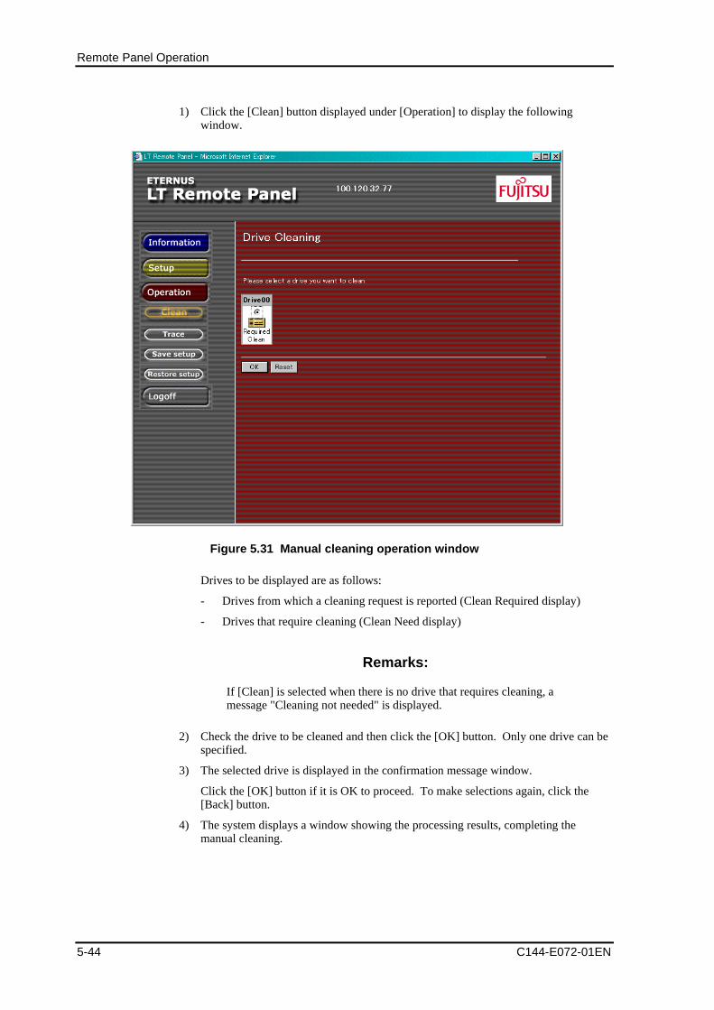
Remote Panel Operation
5-44 C144-E072-01EN
1) Click the [Clean] button displayed under [Operation] to display the followingwindow.
Figure 5.31 Manual cleaning operation window
Drives to be displayed are as follows:
- Drives from which a cleaning request is reported (Clean Required display)
- Drives that require cleaning (Clean Need display)
Remarks:
If [Clean] is selected when there is no drive that requires cleaning, amessage "Cleaning not needed" is displayed.
2) Check the drive to be cleaned and then click the [OK] button. Only one drive can bespecified.
3) The selected drive is displayed in the confirmation message window.
Click the [OK] button if it is OK to proceed. To make selections again, click the[Back] button.
4) The system displays a window showing the processing results, completing themanual cleaning.
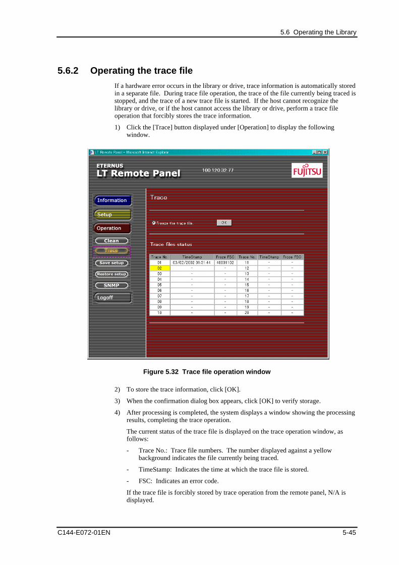
5.6 Operating the Library
C144-E072-01EN 5-45
5.6.2 Operating the trace file
If a hardware error occurs in the library or drive, trace information is automatically storedin a separate file. During trace file operation, the trace of the file currently being traced isstopped, and the trace of a new trace file is started. If the host cannot recognize thelibrary or drive, or if the host cannot access the library or drive, perform a trace fileoperation that forcibly stores the trace information.
1) Click the [Trace] button displayed under [Operation] to display the followingwindow.
Figure 5.32 Trace file operation window
2) To store the trace information, click [OK].
3) When the confirmation dialog box appears, click [OK] to verify storage.
4) After processing is completed, the system displays a window showing the processingresults, completing the trace operation.
The current status of the trace file is displayed on the trace operation window, asfollows:
- Trace No.: Trace file numbers. The number displayed against a yellowbackground indicates the file currently being traced.
- TimeStamp: Indicates the time at which the trace file is stored.
- FSC: Indicates an error code.
If the trace file is forcibly stored by trace operation from the remote panel, N/A isdisplayed.
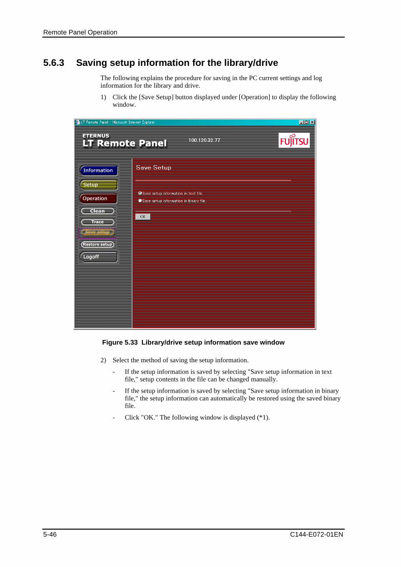
Remote Panel Operation
5-46 C144-E072-01EN
5.6.3 Saving setup information for the library/drive
The following explains the procedure for saving in the PC current settings and loginformation for the library and drive.
1) Click the [Save Setup] button displayed under [Operation] to display the followingwindow.
Figure 5.33 Library/drive setup information save window
2) Select the method of saving the setup information.
- If the setup information is saved by selecting "Save setup information in textfile," setup contents in the file can be changed manually.
- If the setup information is saved by selecting "Save setup information in binaryfile," the setup information can automatically be restored using the saved binaryfile.
- Click "OK." The following window is displayed (*1).
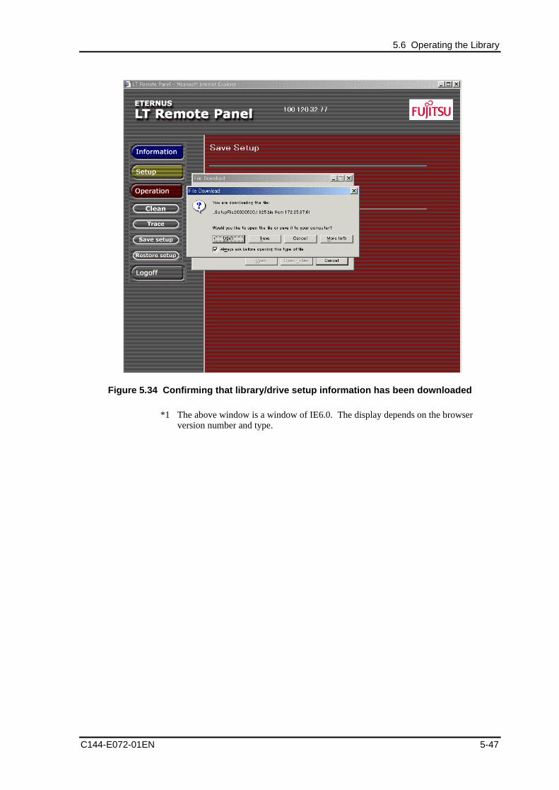
5.6 Operating the Library
C144-E072-01EN 5-47
Figure 5.34 Confirming that library/drive setup information has been downloaded
*1 The above window is a window of IE6.0. The display depends on the browserversion number and type.
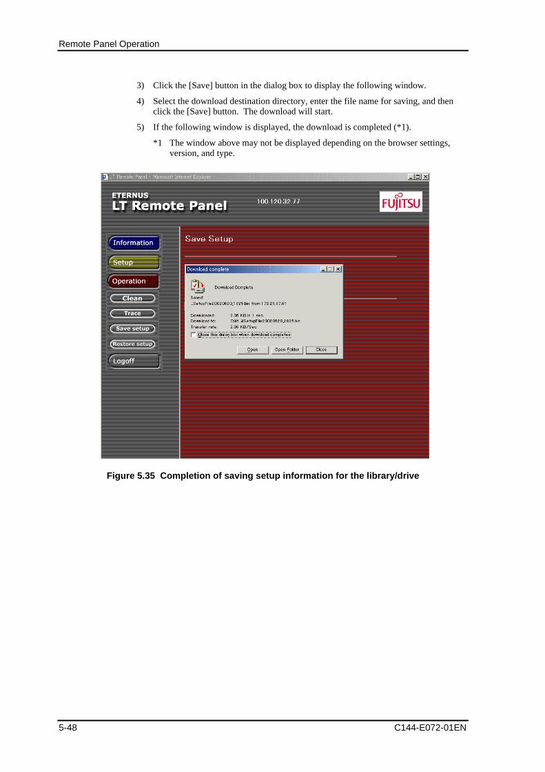
Remote Panel Operation
5-48 C144-E072-01EN
3) Click the [Save] button in the dialog box to display the following window.
4) Select the download destination directory, enter the file name for saving, and thenclick the [Save] button. The download will start.
5) If the following window is displayed, the download is completed (*1).
*1 The window above may not be displayed depending on the browser settings,version, and type.
Figure 5.35 Completion of saving setup information for the library/drive
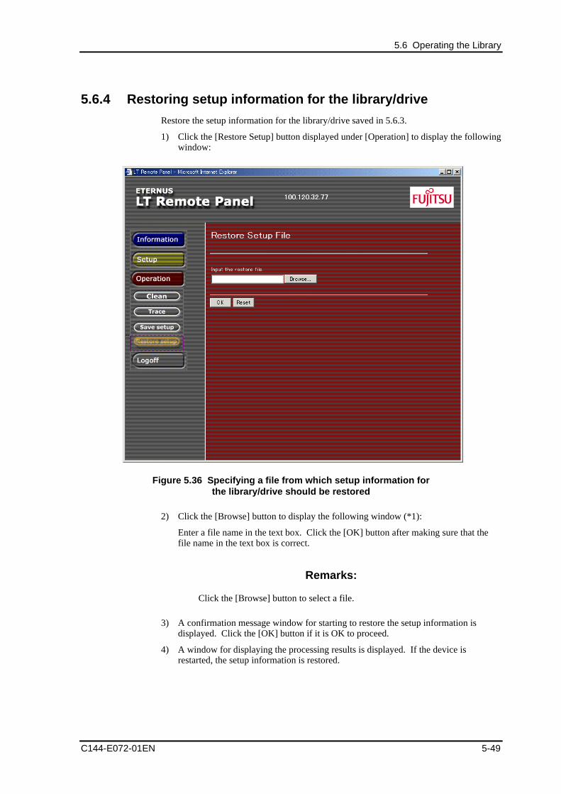
5.6 Operating the Library
C144-E072-01EN 5-49
5.6.4 Restoring setup information for the library/drive
Restore the setup information for the library/drive saved in 5.6.3.
1) Click the [Restore Setup] button displayed under [Operation] to display the followingwindow:
Figure 5.36 Specifying a file from which setup information forthe library/drive should be restored
2) Click the [Browse] button to display the following window (*1):
Enter a file name in the text box. Click the [OK] button after making sure that thefile name in the text box is correct.
Remarks:
Click the [Browse] button to select a file.
3) A confirmation message window for starting to restore the setup information isdisplayed. Click the [OK] button if it is OK to proceed.
4) A window for displaying the processing results is displayed. If the device isrestarted, the setup information is restored.
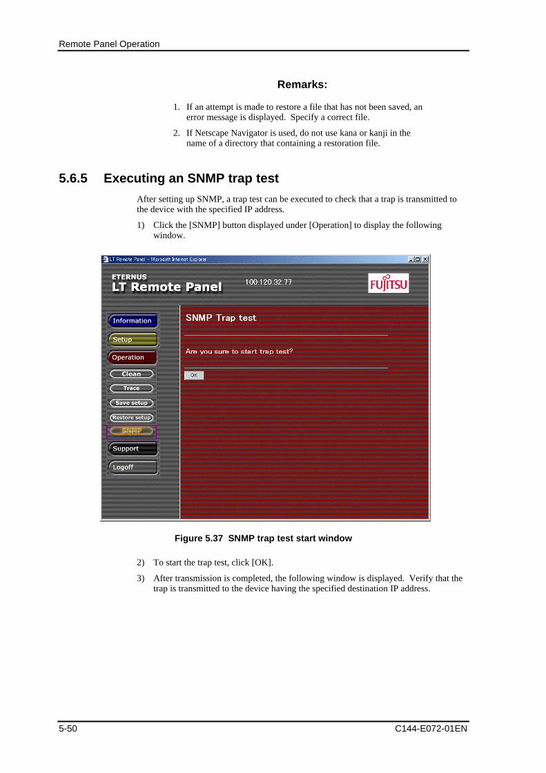
Remote Panel Operation
5-50 C144-E072-01EN
Remarks:
1. If an attempt is made to restore a file that has not been saved, anerror message is displayed. Specify a correct file.
2. If Netscape Navigator is used, do not use kana or kanji in thename of a directory that containing a restoration file.
5.6.5 Executing an SNMP trap test
After setting up SNMP, a trap test can be executed to check that a trap is transmitted tothe device with the specified IP address.
1) Click the [SNMP] button displayed under [Operation] to display the followingwindow.
Figure 5.37 SNMP trap test start window
2) To start the trap test, click [OK].
3) After transmission is completed, the following window is displayed. Verify that thetrap is transmitted to the device having the specified destination IP address.
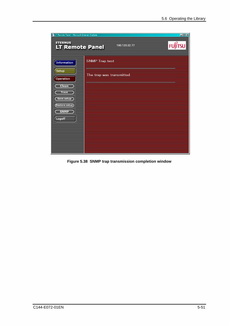
5.6 Operating the Library
C144-E072-01EN 5-51
Figure 5.38 SNMP trap transmission completion window

C144-E072-01EN 6-1
Chapter 6 Troubleshooting
6.1 Drive/Library Maintenance
6.2 Removing Cartridges when an Error Occurs
6.3 Error Status
6.4 General Troubleshooting
6.1 Drive/Library MaintenanceIf a hardware error occurs in the drive or library, Error is displayed on the operator panel,and the error becomes unrecoverable. In this case, maintenance is required.
During the execution of work such as to repair the drive or library or replace parts, it isnecessary to disable the drive to use another one or to stop the operation itself.
6.1.1 Procedure for the drive maintenance
Follow the procedure below to perform the drive maintenance.
Remarks:
Drive maintenance can also be performed while the library isoperating.
1) Disable the drive to be maintained by using the backup software.
2) Perform the drive maintenance (performed by the maintenance person).
3) Enable the drive that has been maintained by using the backup software.
6.1.2 Procedure for the library maintenance
Follow the procedure below to perform the library maintenance.
Turn off the library before starting the library maintenance.
During execution of library maintenance, stop the operation of the backup software.
1) Stop the operation of the backup software.
2) Perform the library maintenance. (Work of a maintenance person.)
3) Resume the operation of backup software.
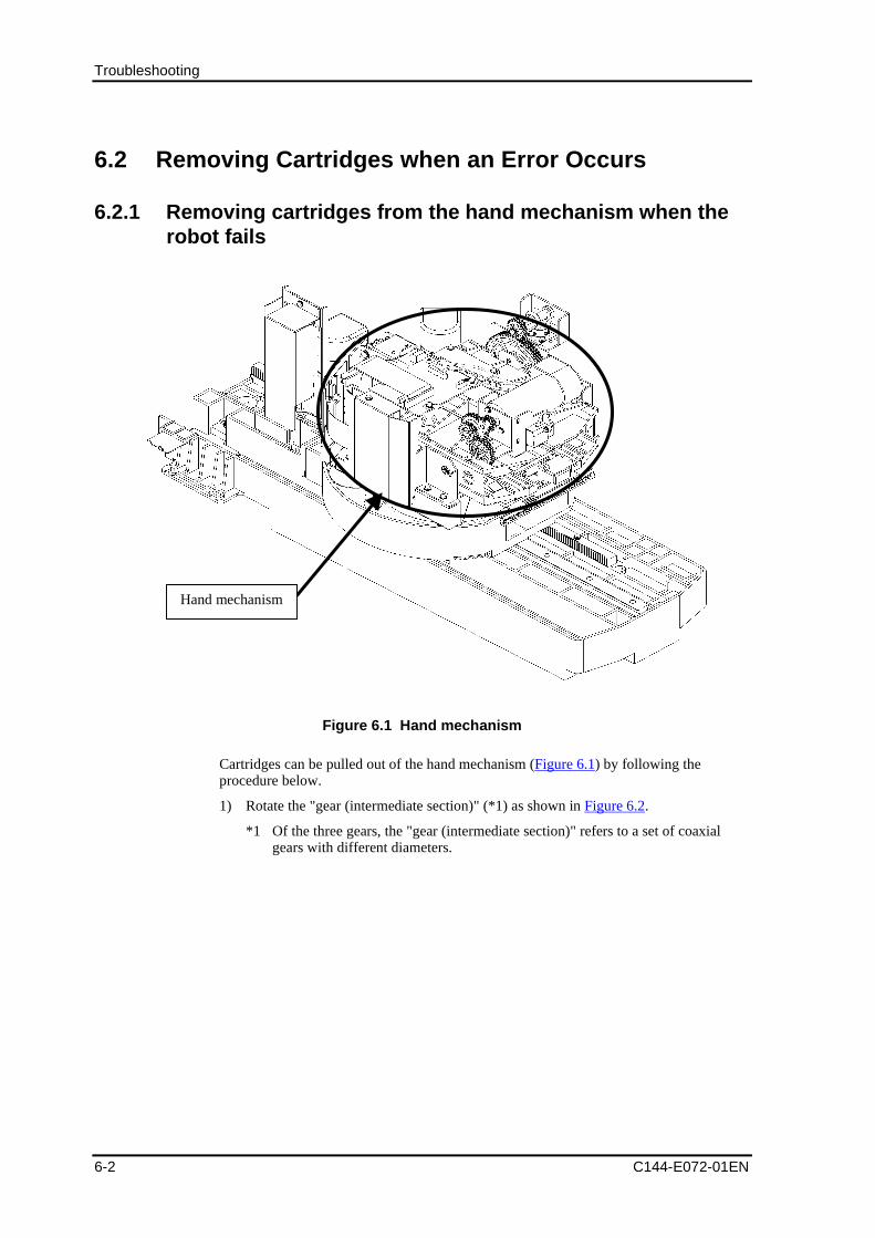
Troubleshooting
6-2 C144-E072-01EN
6.2 Removing Cartridges when an Error Occurs
6.2.1 Removing cartridges from the hand mechanism when therobot fails
Hand mechanism
Figure 6.1 Hand mechanism
Cartridges can be pulled out of the hand mechanism (Figure 6.1) by following theprocedure below.
1) Rotate the "gear (intermediate section)" (*1) as shown in Figure 6.2.
*1 Of the three gears, the "gear (intermediate section)" refers to a set of coaxialgears with different diameters.
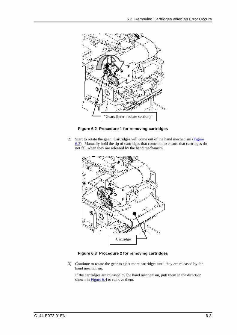
6.2 Removing Cartridges when an Error Occurs
C144-E072-01EN 6-3
"Gears (intermediate section)"
Figure 6.2 Procedure 1 for removing cartridges
2) Start to rotate the gear. Cartridges will come out of the hand mechanism (Figure6.3). Manually hold the tip of cartridges that come out to ensure that cartridges donot fall when they are released by the hand mechanism.
Cartridge
Figure 6.3 Procedure 2 for removing cartridges
3) Continue to rotate the gear to eject more cartridges until they are released by thehand mechanism.
If the cartridges are released by the hand mechanism, pull them in the directionshown in Figure 6.4 to remove them.
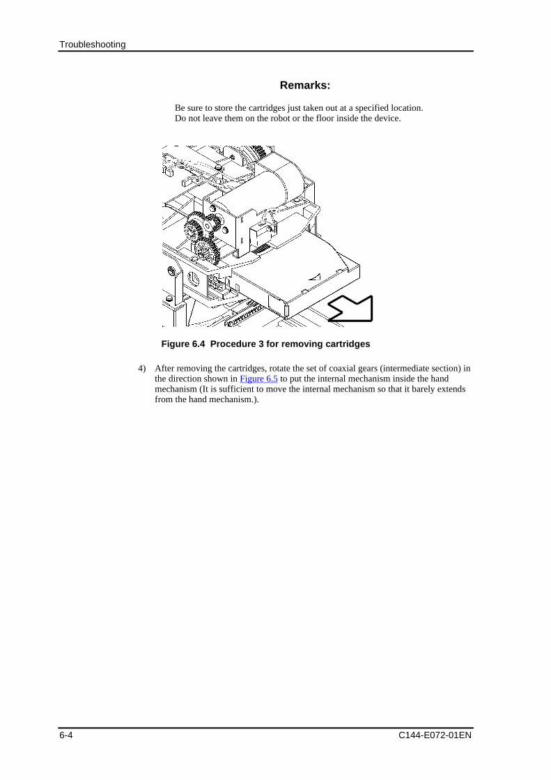
Troubleshooting
6-4 C144-E072-01EN
Remarks:
Be sure to store the cartridges just taken out at a specified location.Do not leave them on the robot or the floor inside the device.
Figure 6.4 Procedure 3 for removing cartridges
4) After removing the cartridges, rotate the set of coaxial gears (intermediate section) inthe direction shown in Figure 6.5 to put the internal mechanism inside the handmechanism (It is sufficient to move the internal mechanism so that it barely extendsfrom the hand mechanism.).
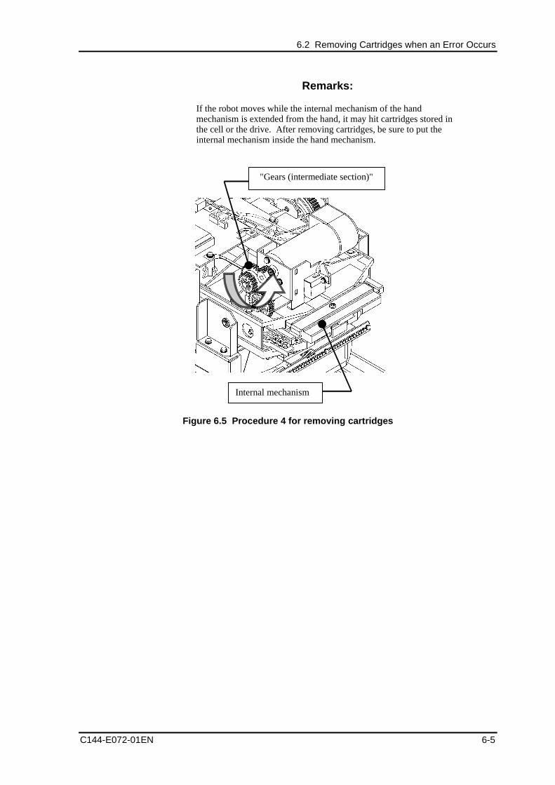
6.2 Removing Cartridges when an Error Occurs
C144-E072-01EN 6-5
Remarks:
If the robot moves while the internal mechanism of the handmechanism is extended from the hand, it may hit cartridges stored inthe cell or the drive. After removing cartridges, be sure to put theinternal mechanism inside the hand mechanism.
"Gears (intermediate section)"
Internal mechanism
Figure 6.5 Procedure 4 for removing cartridges
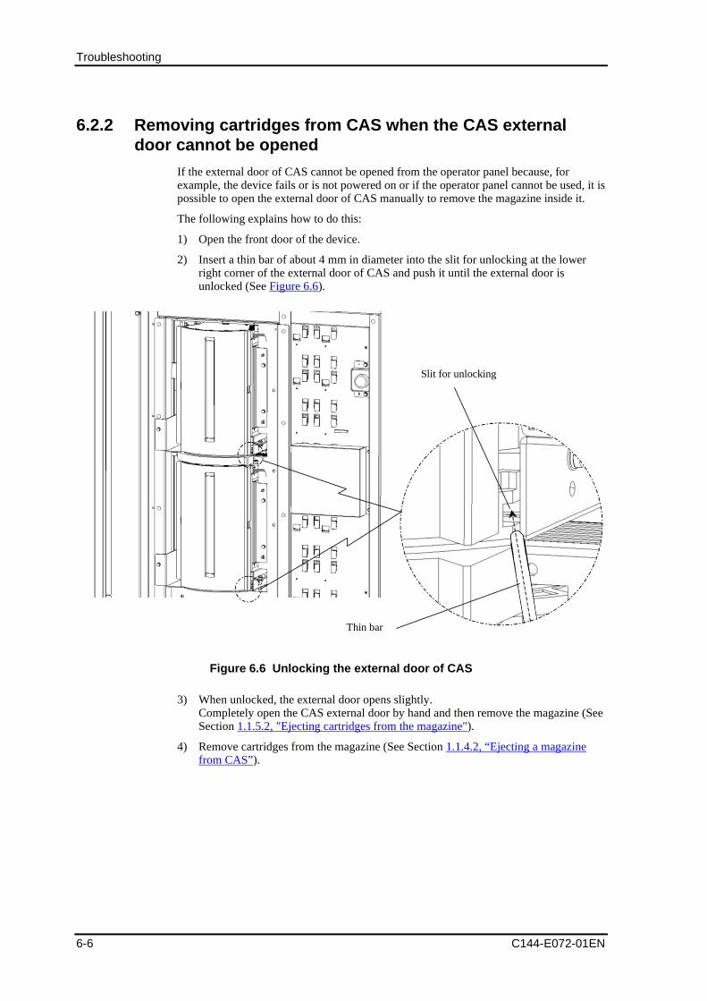
Troubleshooting
6-6 C144-E072-01EN
6.2.2 Removing cartridges from CAS when the CAS externaldoor cannot be opened
If the external door of CAS cannot be opened from the operator panel because, forexample, the device fails or is not powered on or if the operator panel cannot be used, it ispossible to open the external door of CAS manually to remove the magazine inside it.
The following explains how to do this:
1) Open the front door of the device.
2) Insert a thin bar of about 4 mm in diameter into the slit for unlocking at the lowerright corner of the external door of CAS and push it until the external door isunlocked (See Figure 6.6).
Slit for unlocking
Thin bar
Figure 6.6 Unlocking the external door of CAS
3) When unlocked, the external door opens slightly.Completely open the CAS external door by hand and then remove the magazine (SeeSection 1.1.5.2, "Ejecting cartridges from the magazine").
4) Remove cartridges from the magazine (See Section 1.1.4.2, “Ejecting a magazinefrom CAS”).
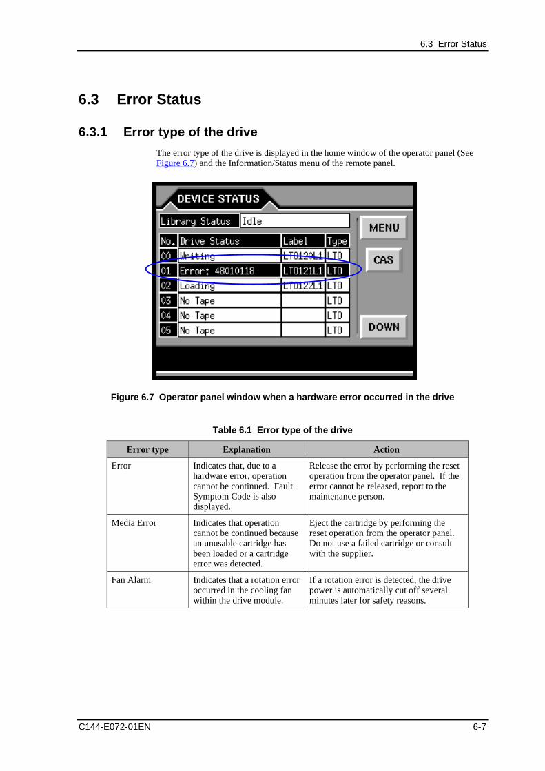
6.3 Error Status
C144-E072-01EN 6-7
6.3 Error Status
6.3.1 Error type of the drive
The error type of the drive is displayed in the home window of the operator panel (SeeFigure 6.7) and the Information/Status menu of the remote panel.
Figure 6.7 Operator panel window when a hardware error occurred in the drive
Table 6.1 Error type of the drive
Error type Explanation Action
Error Indicates that, due to ahardware error, operationcannot be continued. FaultSymptom Code is alsodisplayed.
Release the error by performing the resetoperation from the operator panel. If theerror cannot be released, report to themaintenance person.
Media Error Indicates that operationcannot be continued becausean unusable cartridge hasbeen loaded or a cartridgeerror was detected.
Eject the cartridge by performing thereset operation from the operator panel.Do not use a failed cartridge or consultwith the supplier.
Fan Alarm Indicates that a rotation erroroccurred in the cooling fanwithin the drive module.
If a rotation error is detected, the drivepower is automatically cut off severalminutes later for safety reasons.
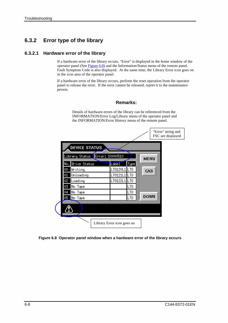
Troubleshooting
6-8 C144-E072-01EN
6.3.2 Error type of the library
6.3.2.1 Hardware error of the library
If a hardware error of the library occurs, "Error" is displayed in the home window of theoperator panel (See Figure 6.8) and the Information/Status menu of the remote panel.Fault Symptom Code is also displayed. At the same time, the Library Error icon goes onin the icon area of the operator panel.
If a hardware error of the library occurs, perform the reset operation from the operatorpanel to release the error. If the error cannot be released, report it to the maintenanceperson.
Remarks:
Details of hardware errors of the library can be referenced from theINFORMATION/Error Log/Library menu of the operator panel andthe INFORMATION/Error History menu of the remote panel.
Figure 6.8 Operator panel window when a hardware error of the library occurs
"Error" string andFSC are displayed
Library Error icon goes on
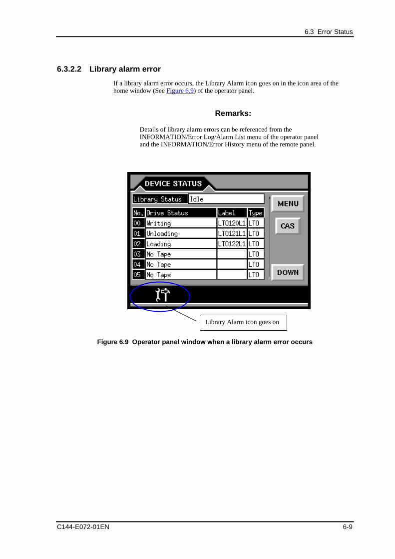
6.3 Error Status
C144-E072-01EN 6-9
6.3.2.2 Library alarm error
If a library alarm error occurs, the Library Alarm icon goes on in the icon area of thehome window (See Figure 6.9) of the operator panel.
Remarks:
Details of library alarm errors can be referenced from theINFORMATION/Error Log/Alarm List menu of the operator paneland the INFORMATION/Error History menu of the remote panel.
Figure 6.9 Operator panel window when a library alarm error occurs
Library Alarm icon goes on
Troubleshooting
6-10 C144-E072-01EN
6.4 General TroubleshootingThis section explains the troubleshooting procedure for this library device. Forinformation about problems and troubleshooting related to the host and applicationsoftware, refer to the manuals for each host system and applications. If the problem stillcannot be solved, report it to the maintenance person.
CAUTION
Data loss: Before turning off and then turning on the power again,consult with the system administrator. Do not turn off and then turnon the power when the interface is active. Otherwise, data loss or ahang-up of the host system may occur.
6.4.1 Power
- Library power is not on.
-- Check all power cable connections.
-- Confirm that the power switch is turned on.
-- Confirm that all power outlets are live. Try other outlets.
-- Confirm that the library is receiving power by checking that the LED lamp onthe back of the device is on and that the fan is rotating.
-- If the problem still cannot be solved, contact maintenance personnel.
- The power-on test fails, or an error message is displayed on the operator panel.
-- Perform recovery from the operator panel.
-- Write down the error code and contact maintenance personnel.
6.4.2 Connections
- The LOOP ID of the drive has been changed, but the host computer cannot identifythe new ID.
-- Confirm that all the devices on the same FC bus have different IDs.
-- Restart the host.
-- Contact maintenance personnel.
- The host does not detect the library.
-- Confirm that the correct HBA is used.
-- Confirm that the addresses are set correctly.
-- Confirm that the operating system, HBA, and driver are set up correctly.
-- Confirm that the zones are set up correctly.
-- Confirm that the cables are connected correctly.
-- Confirm that the operating system recognizes the library as normal.
-- Confirm that the backup software is compatible with the library.
6.4 General Troubleshooting
C144-E072-01EN 6-11
-- Turn on the library again, and turn off the host. Do not turn on the host againuntil the power-on process of the library is completed.
-- To use the Fibre Channel, turn the devices on in the correct order (switch,library, and host).
-- Contact maintenance personnel.
6.4.3 Cartridge
- Writing to tape fails.
-- Confirm that the write protect tab is set to write enabled.
-- Confirm that the overwrite-disabled setting of the backup software is off.
-- Check the file system access permissions of the host device.
-- Confirm that the correct type of tape is being used.
-- Try using a new tape.
CAUTION
Damage to the library: During troubleshooting, do not insert adefective tape into another drive. The defective tape may damage thedrive.
- Tape is stuck in the drive.
-- Turn the library off and then on again, and try using the operator panel to ejectthe tape.
-- Confirm that the backup host software has not reserved the slot. If the slot hasbeen reserved, the reservation must be cancelled.
-- Perform a reset operation from the operator panel to check if the tape is ejected.
Contact maintenance personnel.
6.4.4 CAS
- The CAS cartridge cannot be accessed.
-- From the operator panel, open the target CAS door. Then remove the magazine.
-- Remove the tape.
-- Reinsert the magazine.
-- If the magazine is defective, contact maintenance personnel.
6.4.5 Compatibility
- The cleaning or data cartridge is not compatible with the drive.
-- Confirm that a cleaning or data cartridge compatible with the drive is beingused.
-- Confirm that the correct barcode label is affixed.
Troubleshooting
6-12 C144-E072-01EN
6.4.6 Library performance
- Poor library performance
-- Check the network bandwidth on the host computer.
-- Confirm that the FC path of the drive is not shared with other devices such as adisk unit.
-- Confirm that the drive is clean.
-- Use new tape. The use of deteriorated tape adversely affects performancebecause access is retried on deteriorated sections of the tape.
-- Confirm that fixed-length records (or blocks) are used and that a small recordsize is not set so that the backup software can attain maximum throughput.
-- Confirm that the data is compressed.
6.4.7 Cleaning
- The clean drive icon is displayed if a new cartridge is used.
-- Clean the drive.
-- Replace the cartridge if this icon is displayed again in a short period.
- The cleaning message is displayed repeatedly.
-- Confirm that you are using a cleaning cartridge recommended for the drive typebeing used.
-- Replace the cleaning cartridge with a new one.
-- If this message is displayed again while a specific cartridge is being used, clearthe error message and read the cartridge again. If the cartridge can be read, backup data to another cartridge and dispose of the defective cartridge.
- The cleaning cartridge cannot be loaded.
-- Confirm that you are using a cleaning cartridge recommended for the drive typebeing used.
6.4.8 Operator panel
- The operator panel is not displayed.
-- Confirm that the power cord is connected.
-- Confirm that the power switch is turned on.
-- Confirm that the LED lamp on the rear of the library is on and that the fan isrotating.
-- Confirm that the operator panel's screen saver function is not running.(Touch the operator panel.)
-- Turn the library power off and then on again.
-- Access the library via the remote panel.
-- If the problem still cannot be solved, contact maintenance personnel.
-- Contact maintenance personnel.
- The operator panel is inoperative.
-- Turn the library power off and then on again.
-- Access the library via the remote management card.
6.4 General Troubleshooting
C144-E072-01EN 6-13
-- Access the library from the host computer.
-- Contact maintenance personnel.
6.4.9 Remote panel
- The remote panel cannot be connected.
-- Confirm that the network settings of the device are correct.
-- Confirm that cookies and JavaScript are enabled in the browser settings.
-- The recommended browsers are Microsoft Internet Explorer 5.0 to 6.0 andNetscape Navigator 4.7 to 4.78.
-- Replace the LAN cable.
-- Contact maintenance personnel.
- The login password for a user or user administrator has been forgotten.
-- Contact maintenance personnel.

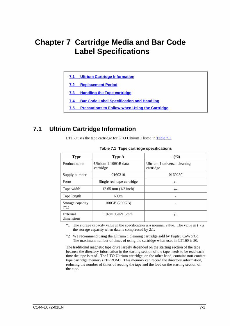
C144-E072-01EN 7-1
Chapter 7 Cartridge Media and Bar CodeLabel Specifications
7.1 Ultrium Cartridge Information
7.2 Replacement Period
7.3 Handling the Tape cartridge
7.4 Bar Code Label Specification and Handling
7.5 Precautions to Follow when Using the Cartridge
7.1 Ultrium Cartridge InformationLT160 uses the tape cartridge for LTO Ultrium 1 listed in Table 7.1.
Table 7.1 Tape cartridge specifications
Type Type A - (*2)
Product name Ultrium 1 100GB datacartridge
Ultrium 1 universal cleaningcartridge
Supply number 0160210 0160280
Form Single reel tape cartridge
Tape width 12.65 mm (1/2 inch)
Tape length 609m -
Storage capacity(*1)
100GB (200GB) -
Externaldimensions
102×105×21.5mm
*1 The storage capacity value in the specification is a nominal value. The value in ( ) isthe storage capacity when data is compressed by 2:1.
*2 We recommend using the Ultrium 1 cleaning cartridge sold by Fujitsu CoWorCo.The maximum number of times of using the cartridge when used in LT160 is 50.
The traditional magnetic tape drive largely depended on the starting section of the tapebecause the directory information in the starting section of the tape needs to be read eachtime the tape is read. The LTO Ultrium cartridge, on the other hand, contains non-contacttype cartridge memory (EEPROM). This memory can record the directory information,reducing the number of times of reading the tape and the load on the starting section ofthe tape.
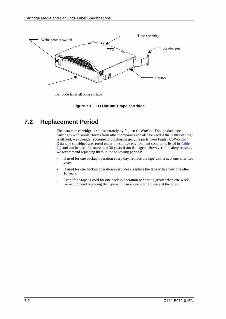
Cartridge Media and Bar Code Label Specifications
7-2 C144-E072-01EN
Tape cartridge
Reader pin
Shutter
Write protect switch
Bar code label affixing surface
Figure 7.1 LTO Ultrium 1 tape cartridge
7.2 Replacement PeriodThe data tape cartridge is sold separately by Fujitsu CoWorCo. Though data tapecartridges with similar forms from other companies can also be used if the "Ultrium" logois affixed, we strongly recommend purchasing genuine parts from Fujitsu CoWorCo.Data tape cartridges are stored under the storage environment conditions listed in Table7.2 and can be used for more than 30 years if not damaged. However, for safety reasons,we recommend replacing them in the following periods:
- If used for one backup operation every day, replace the tape with a new one after twoyears.
- If used for one backup operation every week, replace the tape with a new one after10 years.
- Even if the tape is used for one backup operation per period greater than one week,we recommend replacing the tape with a new one after 10 years at the latest.
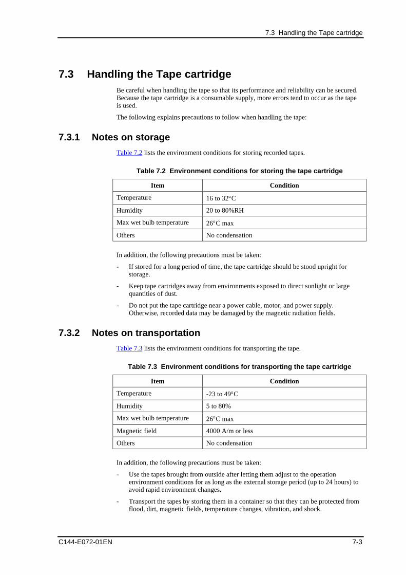
7.3 Handling the Tape cartridge
C144-E072-01EN 7-3
7.3 Handling the Tape cartridgeBe careful when handling the tape so that its performance and reliability can be secured.Because the tape cartridge is a consumable supply, more errors tend to occur as the tapeis used.
The following explains precautions to follow when handling the tape:
7.3.1 Notes on storage
Table 7.2 lists the environment conditions for storing recorded tapes.
Table 7.2 Environment conditions for storing the tape cartridge
Item Condition
Temperature 16 to 32 C
Humidity 20 to 80%RH
Max wet bulb temperature 26 C max
Others No condensation
In addition, the following precautions must be taken:
- If stored for a long period of time, the tape cartridge should be stood upright forstorage.
- Keep tape cartridges away from environments exposed to direct sunlight or largequantities of dust.
- Do not put the tape cartridge near a power cable, motor, and power supply.Otherwise, recorded data may be damaged by the magnetic radiation fields.
7.3.2 Notes on transportation
Table 7.3 lists the environment conditions for transporting the tape.
Table 7.3 Environment conditions for transporting the tape cartridge
Item Condition
Temperature -23 to 49 C
Humidity 5 to 80%
Max wet bulb temperature 26 C max
Magnetic field 4000 A/m or less
Others No condensation
In addition, the following precautions must be taken:
- Use the tapes brought from outside after letting them adjust to the operationenvironment conditions for as long as the external storage period (up to 24 hours) toavoid rapid environment changes.
- Transport the tapes by storing them in a container so that they can be protected fromflood, dirt, magnetic fields, temperature changes, vibration, and shock.
Cartridge Media and Bar Code Label Specifications
7-4 C144-E072-01EN
7.3.3 Notes on handling
- Do not stack tape cartridges high because they may be damaged by falling (stackvolumes up to six high). If a tape cartridge is mistakenly damaged by falling,perform data migration immediately after data recovery and then discard thedamaged tape cartridge.
- The support track is written into the LTO Ultrium 1 tape cartridge in advance andcorrect read/write operations are performed based on this information. Though it ispossible to delete data using a special device (1200 oersted or more) for the purposeof ensuring data security, the tape whose data has been deleted cannot be reusedbecause the support track has also been deleted.
- Adhesive constituents of binder in the tape may melt and adhere to the magnetichead, corroding the MR elements in the head and causing read/write errors. Thisresults from chemical deterioration of the tape and has nothing to do with the numberof times of using the tape. Thus, this problem cannot be resolved by cleaning thetape. Because those constituents tend to melt with the increasing temperature andhumidity at which the tape cartridge is stored, sufficient attention needs to be paid tothe storage environment conditions. Dispose of tapes with the head to which thoseconstituents adhere.
7.3.4 Notes on the reader pin
- Before inserting into the device, make sure that the reader pin is on the tapecartridge. If the reader pin has been detached from a recorded tape, attaching thereader pin to the tape can make the tape reusable. However, only the first 30 cmfrom the tape tip can be restored.
- When loading the tape, make sure that the reader pin is securely latched.
- Because the tape cartridge is a precision-made product, do not apply unreasonableforce or pull out the reader pin and tape. Do not push or rotate the reel.
7.3.5 Notes on label affixing
Affix highly adhesive labels to the tape. Labels that come off inside the device maycause device failures. Use labels supplied with the tape or genuine labels sold by FujitsuCoWorCo.
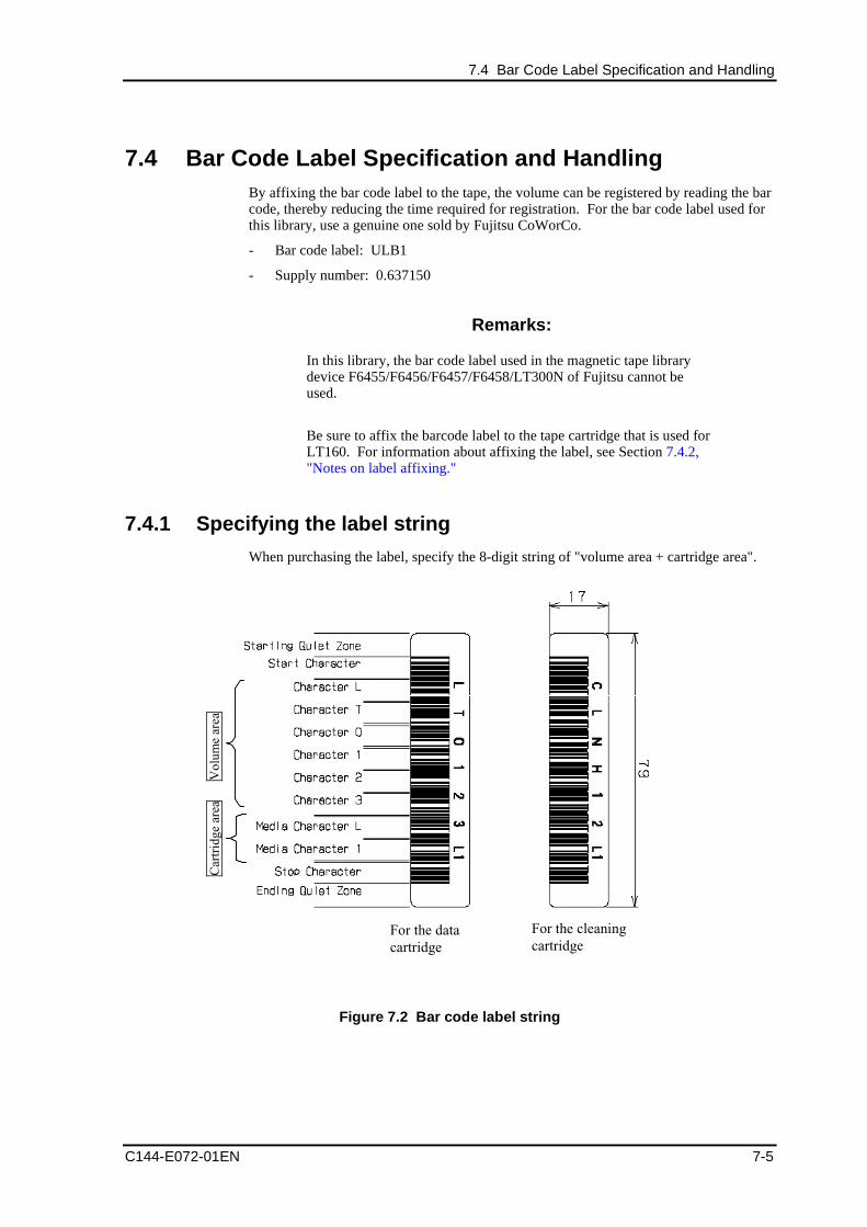
7.4 Bar Code Label Specification and Handling
C144-E072-01EN 7-5
7.4 Bar Code Label Specification and HandlingBy affixing the bar code label to the tape, the volume can be registered by reading the barcode, thereby reducing the time required for registration. For the bar code label used forthis library, use a genuine one sold by Fujitsu CoWorCo.
- Bar code label: ULB1
- Supply number: 0.637150
Remarks:
In this library, the bar code label used in the magnetic tape librarydevice F6455/F6456/F6457/F6458/LT300N of Fujitsu cannot beused.
Be sure to affix the barcode label to the tape cartridge that is used forLT160. For information about affixing the label, see Section 7.4.2,"Notes on label affixing."
7.4.1 Specifying the label string
When purchasing the label, specify the 8-digit string of "volume area + cartridge area".
For the datacartridge
For the cleaningcartridge
Vol
ume
area
Car
trid
ge a
rea
Figure 7.2 Bar code label string
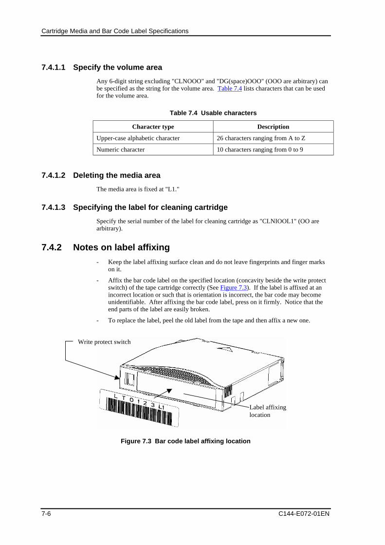
Cartridge Media and Bar Code Label Specifications
7-6 C144-E072-01EN
7.4.1.1 Specify the volume area
Any 6-digit string excluding "CLNOOO" and "DG(space)OOO" (OOO are arbitrary) canbe specified as the string for the volume area. Table 7.4 lists characters that can be usedfor the volume area.
Table 7.4 Usable characters
Character type Description
Upper-case alphabetic character 26 characters ranging from A to Z
Numeric character 10 characters ranging from 0 to 9
7.4.1.2 Deleting the media area
The media area is fixed at "L1."
7.4.1.3 Specifying the label for cleaning cartridge
Specify the serial number of the label for cleaning cartridge as "CLNIOOL1" (OO arearbitrary).
7.4.2 Notes on label affixing
- Keep the label affixing surface clean and do not leave fingerprints and finger markson it.
- Affix the bar code label on the specified location (concavity beside the write protectswitch) of the tape cartridge correctly (See Figure 7.3). If the label is affixed at anincorrect location or such that is orientation is incorrect, the bar code may becomeunidentifiable. After affixing the bar code label, press on it firmly. Notice that theend parts of the label are easily broken.
- To replace the label, peel the old label from the tape and then affix a new one.
Label affixinglocation
Write protect switch
Figure 7.3 Bar code label affixing location
7.5 Precautions to Follow when Using the Cartridge
C144-E072-01EN 7-7
7.5 Precautions to Follow when Using the Cartridge- The tape drive of LT160 is dedicated for the LTO Ultrium 1 tape cartridge. Tape
cartridges such as DLT, 8 mm, DAT, and LT300 cannot be used. The tape cartridgefor LT120 can be used.
- The tape cartridge for recording data and the cleaning cartridge are consumablesupplies. Although one volume of each cartridge is supplied with the device, be sureto purchase them separately. For details of the specifications, see Section 7.1,"Ultrium Cartridge Information."
- The cleaning cartridge can be used a maximum of 50 times. If the maximum numberis reached, replace the cleaning cartridge.
- The cleaning cartridge for an LT120 cannot be used.
- To use a tape cartridge that was used in another library device in this library, checkthe following points. If any relevant point is found, perform recovery work orreplacement with a new one before using LT160.
-- Label
Use a genuine Fujitsu CoWorCo label for the bar code label to be affixed to thecartridge. For details of the specifications, see Section 7.4, "Bar Code LabelSpecifications and Handling."
-- Reader pin
Check for any reader pin that has been detached from the cartridge. For details,see Section 7.3.4, "Notes on the reader pin."
-- Replacement period of the tape cartridge
The tape cartridge is consumed due to mechanical abrasion and chemicaldeterioration of magnetic material. If storage under the environment conditionsrecommended by Fujitsu is assumed, the service life of the tape cartridge isabout 30 years. However, if circumstances such as the environment for use,number of times of use, and storage environment are considered for actualoperation, we recommend replacing the tape cartridge with a new one, followingas guideline the replacement period described in Section 7.2, "ReplacementPeriod."

C144-E072-01EN A-1
Appendix A Model Configuration
A.1 Model Configuration of Basic Model A20 (10 drive options/98 celloptions/10 CASs)
A.2 Model Configuration of Basic Model A20 (10 drive options/182 celloptions/10 CASs)
A.3 Model Configuration of Basic Model A20 (10 drive options/221 celloptions/10 CASs)
A.4 Model Configuration of Basic Model A32 (16 drive options/89 celloptions/10 CASs)
A.5 Model Configuration of Basic Model A32 (16 drive options/167 celloptions/10 CASs)
The following table lists the configuration of the numbers of cell options, drive options,and CAS of the two basic models (A20 and A32).
Basic modelname
Cell option (numberof cells)
Drive option(number of drives)
CAS (*)
A20 98 182 221 10 (Max) 10 (2)
A32 89 167 -- 16 (Max) 10 (2)
Note: The value in ( ) is the number of magazines.
The following shows each model configuration in this appendix.
Remarks:
Explanation of symbols in the configuration diagram of each modelF: Indicates a flag for positioning the accessor (cartridge transport
element).EX: Indicates an Exchange cell.R: Indicates a reserve cell.D: Indicates a diagnostics cell.CL: Indicates a cleaning cell.Other values indicate a CAS, cell, or drive that is used from theoperator panel or remote panel.
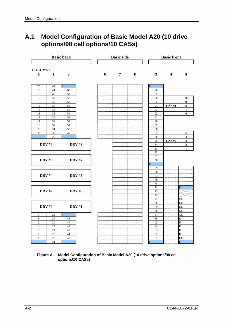
Model Configuration
A-2 C144-E072-01EN
A.1 Model Configuration of Basic Model A20 (10 driveoptions/98 cell options/10 CASs)
COLUMNS0 1 2 6 7 8 3 4 5
20 42 F F19 41 60 9818 40 59 9717 39 58 96 1016 38 57 95 915 37 56 94 CAS #1 814 36 55 93 713 35 54 92 612 34 53 9111 33 52 9010 32 51 899 31 50 888 30 49 87 5
F 29 F 86 485 CAS #0 384 283 1828180
F797877767574 F737271 CL70 CL69 CL68 CL
7 28 F 67 CL6 27 48 66 D5 26 47 65 D4 25 46 64 D3 24 45 63 R2 23 44 62 R1 22 43 61 EX
F 21 F F F
Basic back Basic side Basic front
DRV #4 DRV #5
DRV #8 DRV #9
DRV #6 DRV #7
DRV #0 DRV #1
DRV #2 DRV #3
Figure A.1 Model Configuration of Basic Model A20 (10 drive options/98 celloptions/10 CASs)
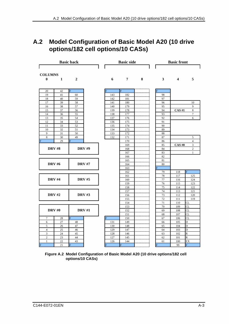
A.2 Model Configuration of Basic Model A20 (10 drive options/182 cell options/10 CASs)
C144-E072-01EN A-3
A.2 Model Configuration of Basic Model A20 (10 driveoptions/182 cell options/10 CASs)
COLUMNS0 1 2 6 7 8 3 4 5
20 42 F F F F19 41 60 143 182 9818 40 59 142 181 9717 39 58 141 180 96 1016 38 57 140 179 95 915 37 56 139 178 94 CAS #1 814 36 55 138 177 93 713 35 54 137 176 92 612 34 53 136 175 9111 33 52 135 174 9010 32 51 134 173 899 31 50 133 172 888 30 49 132 171 87 5
F 29 F 170 86 4169 85 CAS #0 3168 84 2167 83 1166 82165 81164 80163 F162 79 118 F161 78 117 125160 77 116 124159 76 115 123158 75 114 122157 74 113 121156 73 112 120155 72 111 119154 71 110 CL153 70 109 CL152 69 108 CL151 68 107 CL
7 28 F F 150 67 106 CL6 27 48 131 149 66 105 D5 26 47 130 148 65 104 D4 25 46 129 147 64 103 D3 24 45 128 146 63 102 R2 23 44 127 145 62 101 R1 22 43 126 144 61 100 EX
F 21 F F F F 99 F
Basic front
DRV #0 DRV #1
DRV #2 DRV #3
DRV #4 DRV #5
DRV #8 DRV #9
DRV #6 DRV #7
Basic back Basic side
Figure A.2 Model Configuration of Basic Model A20 (10 drive options/182 celloptions/10 CASs)
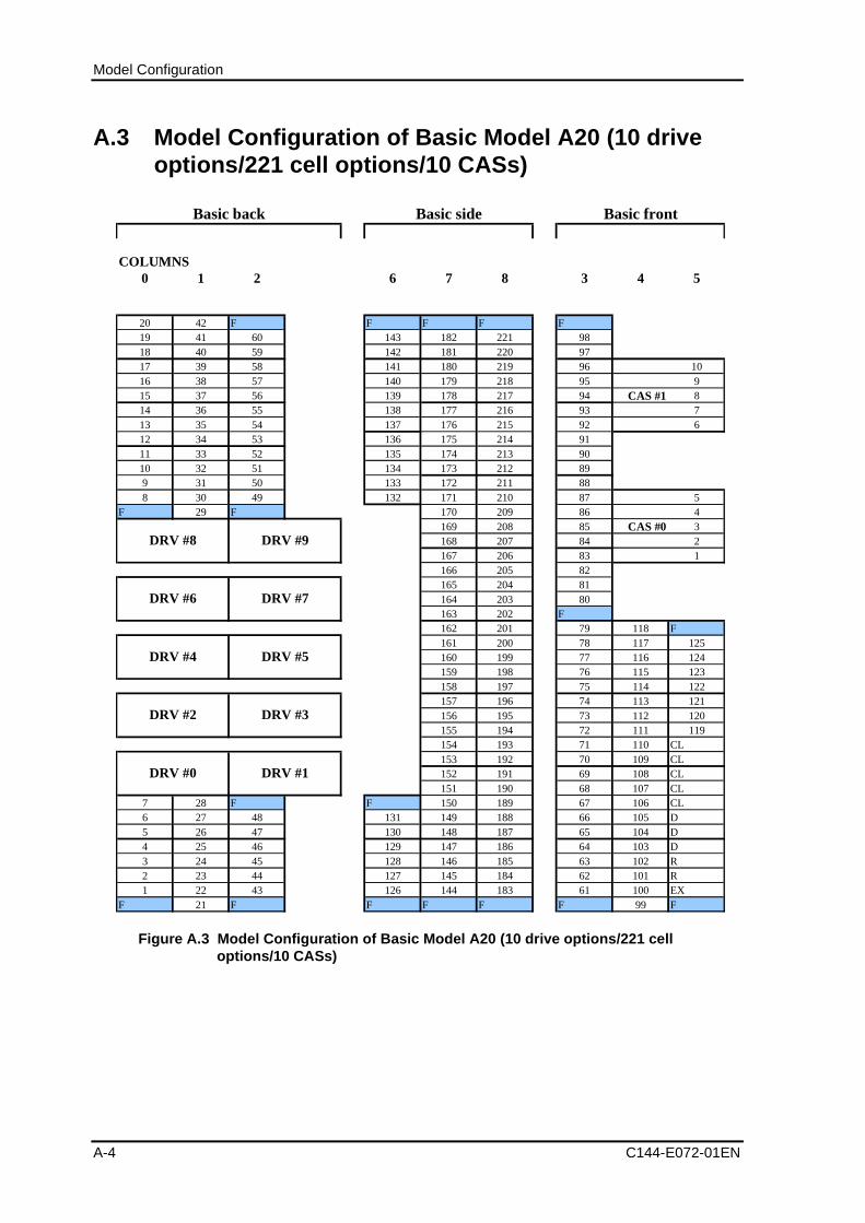
Model Configuration
A-4 C144-E072-01EN
A.3 Model Configuration of Basic Model A20 (10 driveoptions/221 cell options/10 CASs)
COLUMNS0 1 2 6 7 8 3 4 5
20 42 F F F F F19 41 60 143 182 221 9818 40 59 142 181 220 9717 39 58 141 180 219 96 1016 38 57 140 179 218 95 915 37 56 139 178 217 94 CAS #1 814 36 55 138 177 216 93 713 35 54 137 176 215 92 612 34 53 136 175 214 9111 33 52 135 174 213 9010 32 51 134 173 212 899 31 50 133 172 211 888 30 49 132 171 210 87 5
F 29 F 170 209 86 4169 208 85 CAS #0 3168 207 84 2167 206 83 1166 205 82165 204 81164 203 80163 202 F162 201 79 118 F161 200 78 117 125160 199 77 116 124159 198 76 115 123158 197 75 114 122157 196 74 113 121156 195 73 112 120155 194 72 111 119154 193 71 110 CL153 192 70 109 CL152 191 69 108 CL151 190 68 107 CL
7 28 F F 150 189 67 106 CL6 27 48 131 149 188 66 105 D5 26 47 130 148 187 65 104 D4 25 46 129 147 186 64 103 D3 24 45 128 146 185 63 102 R2 23 44 127 145 184 62 101 R1 22 43 126 144 183 61 100 EX
F 21 F F F F F 99 F
Basic front
DRV #0 DRV #1
DRV #4 DRV #5
DRV #2 DRV #3
DRV #8 DRV #9
DRV #6 DRV #7
Basic back Basic side
Figure A.3 Model Configuration of Basic Model A20 (10 drive options/221 celloptions/10 CASs)
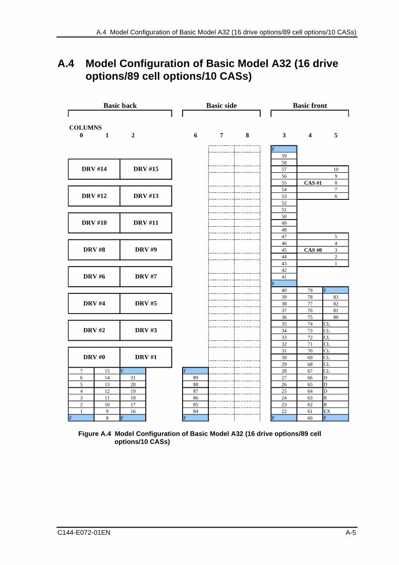
A.4 Model Configuration of Basic Model A32 (16 drive options/89 cell options/10 CASs)
C144-E072-01EN A-5
A.4 Model Configuration of Basic Model A32 (16 driveoptions/89 cell options/10 CASs)
COLUMNS0 1 2 6 7 8 3 4 5
F595857 1056 955 CAS #1 854 753 6525150494847 546 445 CAS #0 344 243 14241
F 40 79 F
39 78 8338 77 8237 76 8136 75 8035 74 CL34 73 CL33 72 CL32 71 CL31 70 CL30 69 CL29 68 CL
7 15 F F 28 67 CL6 14 21 89 27 66 D5 13 20 88 26 65 D4 12 19 87 25 64 D3 11 18 86 24 63 R2 10 17 85 23 62 R1 9 16 84 22 61 EX
F 8 F F F 60 F
Basic back Basic side Basic front
DRV #14 DRV #15
DRV #12 DRV #13
DRV #10 DRV #11
DRV #8 DRV #9
DRV #2 DRV #3
DRV #0 DRV #1
DRV #6 DRV #7
DRV #4 DRV #5
�����������������������������������������������������������������������������������������������������������������������������������������������������������������������������������������������������������������������������������������������������������������������������������������������������������������������������������������������������������������������������������������������������������������������������������������������������������������������������������������������������������������������������������������������������������������������������������������������������������������������������������������������������������������������������������������������������������������������������������������������������������������������������������������������������������������������������������������������������������������������������������������������������������������������������������������������������������������������������������������������������������������������������������������������������������������������������������������������������������������������������������������������������������������������������������������������������������������������������������������������������������������������������������������������������������������������������������������������������������������������������������������������������������������������������������������������������������������������������������������������������������������������������������������������������������������
���������������������������������������������������������������������������������������������������������������������������������������������������������������������������������������������������������������������������������������������������������������������������������������������������������������������������������������������������������������������������������������������������������������������������������������������������������������
���������������������������������������������������������������������������������������������������������������
���������������������������������������������������������������������������������������������������������������
Figure A.4 Model Configuration of Basic Model A32 (16 drive options/89 celloptions/10 CASs)
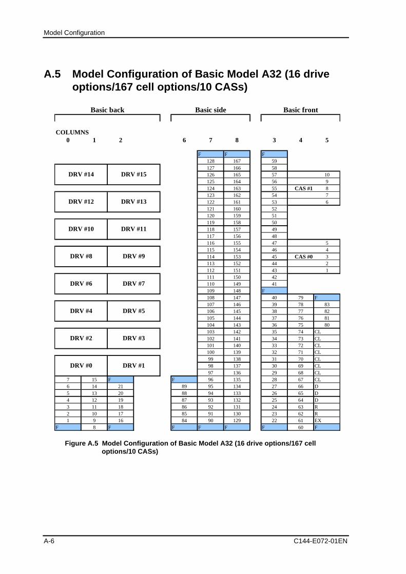
Model Configuration
A-6 C144-E072-01EN
A.5 Model Configuration of Basic Model A32 (16 driveoptions/167 cell options/10 CASs)
COLUMNS0 1 2 6 7 8 3 4 5
F F F128 167 59127 166 58126 165 57 10125 164 56 9124 163 55 CAS #1 8123 162 54 7122 161 53 6121 160 52120 159 51119 158 50118 157 49117 156 48116 155 47 5115 154 46 4114 153 45 CAS #0 3113 152 44 2112 151 43 1111 150 42110 149 41109 148 F108 147 40 79 F107 146 39 78 83106 145 38 77 82105 144 37 76 81104 143 36 75 80103 142 35 74 CL102 141 34 73 CL101 140 33 72 CL100 139 32 71 CL99 138 31 70 CL98 137 30 69 CL97 136 29 68 CL
7 15 F F 96 135 28 67 CL6 14 21 89 95 134 27 66 D5 13 20 88 94 133 26 65 D4 12 19 87 93 132 25 64 D3 11 18 86 92 131 24 63 R2 10 17 85 91 130 23 62 R1 9 16 84 90 129 22 61 EX
F 8 F F F F F 60 F
Basic back Basic side Basic front
DRV #2 DRV #3
DRV #10 DRV #11
DRV #8 DRV #9
DRV #14 DRV #15
DRV #12 DRV #13
DRV #0 DRV #1
DRV #6 DRV #7
DRV #4 DRV #5
Figure A.5 Model Configuration of Basic Model A32 (16 drive options/167 celloptions/10 CASs)
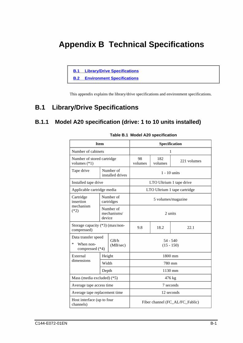
C144-E072-01EN B-1
Appendix B Technical Specifications
B.1 Library/Drive Specifications
B.2 Environment Specifications
This appendix explains the library/drive specifications and environment specifications.
B.1 Library/Drive Specifications
B.1.1 Model A20 specification (drive: 1 to 10 units installed)
Table B.1 Model A20 specification
Item Specification
Number of cabinets 1
Number of stored cartridgevolumes (*1)
98volumes
182volumes
221 volumes
Tape drive Number ofinstalled drives
1 - 10 units
Installed tape drive LTO Ultrium 1 tape drive
Applicable cartridge media LTO Ultrium 1 tape cartridge
Number ofcartridges
5 volumes/magazineCartridgeinsertionmechanism(*2) Number of
mechanisms/device
2 units
Storage capacity (*3) (max/non-compressed)
9.8 18.2 22.1
Data transfer speed
* When non-compressed (*4)
GB/h(MB/sec)
54 - 540(15 - 150)
Height 1800 mm
Width 780 mm
Externaldimensions
Depth 1130 mm
Mass (media excluded) (*5) 476 kg
Average tape access time 7 seconds
Average tape replacement time 12 seconds
Host interface (up to fourchannels)
Fiber channel (FC_AL/FC_Fablic)
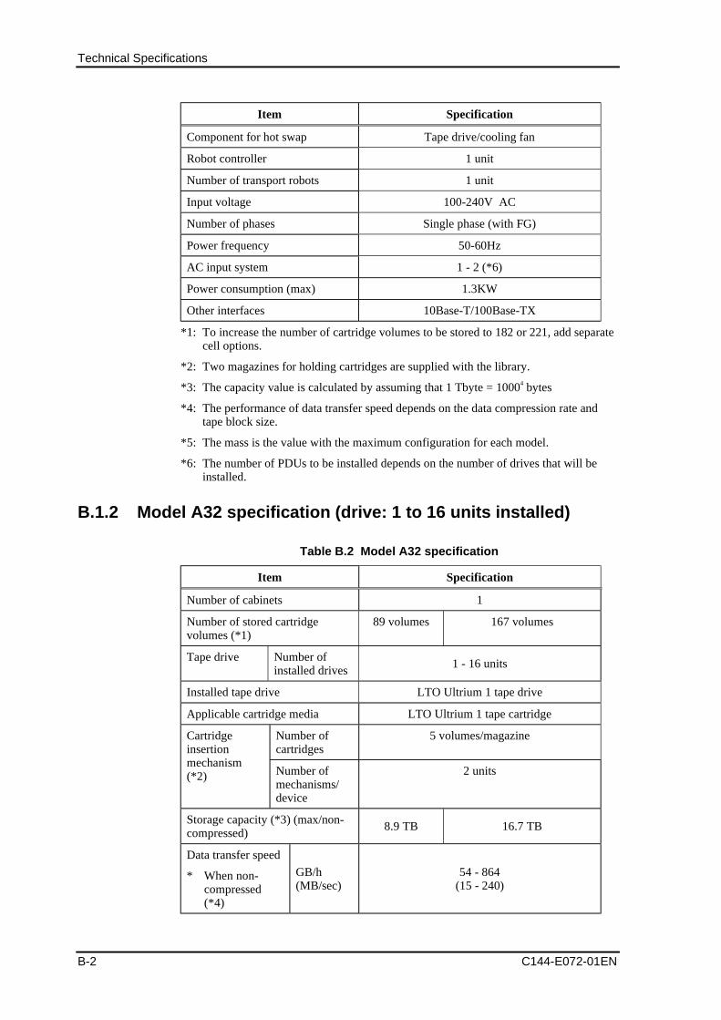
Technical Specifications
B-2 C144-E072-01EN
Item Specification
Component for hot swap Tape drive/cooling fan
Robot controller 1 unit
Number of transport robots 1 unit
Input voltage 100-240V AC
Number of phases Single phase (with FG)
Power frequency 50-60Hz
AC input system 1 - 2 (*6)
Power consumption (max) 1.3KW
Other interfaces 10Base-T/100Base-TX
*1: To increase the number of cartridge volumes to be stored to 182 or 221, add separatecell options.
*2: Two magazines for holding cartridges are supplied with the library.
*3: The capacity value is calculated by assuming that 1 Tbyte = 10004 bytes
*4: The performance of data transfer speed depends on the data compression rate andtape block size.
*5: The mass is the value with the maximum configuration for each model.
*6: The number of PDUs to be installed depends on the number of drives that will beinstalled.
B.1.2 Model A32 specification (drive: 1 to 16 units installed)
Table B.2 Model A32 specification
Item Specification
Number of cabinets 1
Number of stored cartridgevolumes (*1)
89 volumes 167 volumes
Tape drive Number ofinstalled drives
1 - 16 units
Installed tape drive LTO Ultrium 1 tape drive
Applicable cartridge media LTO Ultrium 1 tape cartridge
Number ofcartridges
5 volumes/magazineCartridgeinsertionmechanism(*2) Number of
mechanisms/device
2 units
Storage capacity (*3) (max/non-compressed)
8.9 TB 16.7 TB
Data transfer speed
* When non-compressed(*4)
GB/h(MB/sec)
54 - 864(15 - 240)
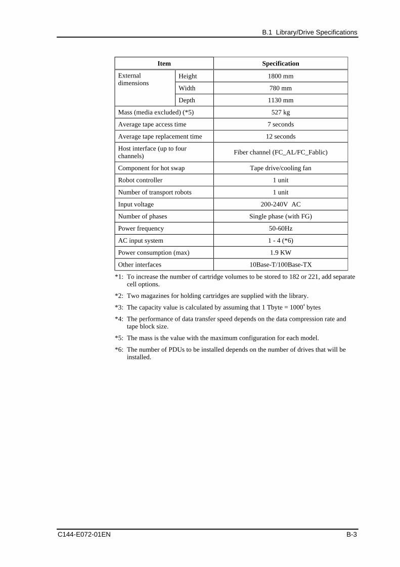
B.1 Library/Drive Specifications
C144-E072-01EN B-3
Item Specification
Height 1800 mm
Width 780 mm
Externaldimensions
Depth 1130 mm
Mass (media excluded) (*5) 527 kg
Average tape access time 7 seconds
Average tape replacement time 12 seconds
Host interface (up to fourchannels)
Fiber channel (FC_AL/FC_Fablic)
Component for hot swap Tape drive/cooling fan
Robot controller 1 unit
Number of transport robots 1 unit
Input voltage 200-240V AC
Number of phases Single phase (with FG)
Power frequency 50-60Hz
AC input system 1 - 4 (*6)
Power consumption (max) 1.9 KW
Other interfaces 10Base-T/100Base-TX
*1: To increase the number of cartridge volumes to be stored to 182 or 221, add separatecell options.
*2: Two magazines for holding cartridges are supplied with the library.
*3: The capacity value is calculated by assuming that 1 Tbyte = 10004 bytes
*4: The performance of data transfer speed depends on the data compression rate andtape block size.
*5: The mass is the value with the maximum configuration for each model.
*6: The number of PDUs to be installed depends on the number of drives that will beinstalled.
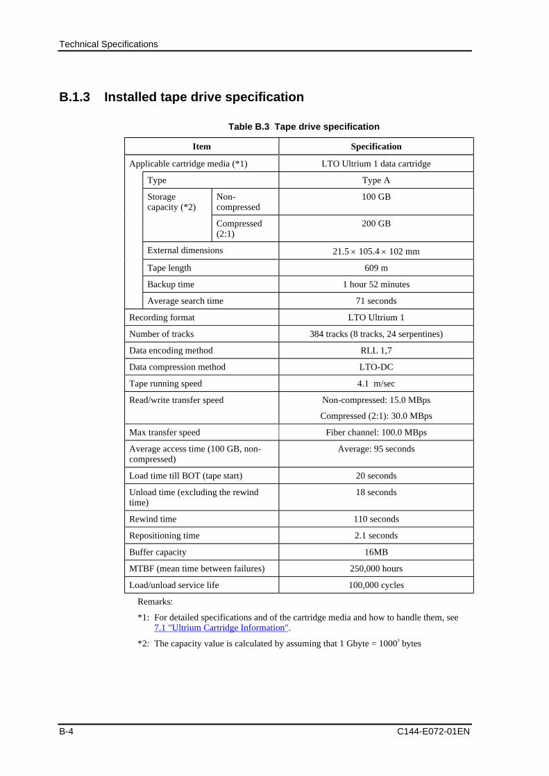
Technical Specifications
B-4 C144-E072-01EN
B.1.3 Installed tape drive specification
Table B.3 Tape drive specification
Item Specification
Applicable cartridge media (*1) LTO Ultrium 1 data cartridge
Type Type A
Non-compressed
100 GBStoragecapacity (*2)
Compressed(2:1)
200 GB
External dimensions 21.5 105.4 102 mm
Tape length 609 m
Backup time 1 hour 52 minutes
Average search time 71 seconds
Recording format LTO Ultrium 1
Number of tracks 384 tracks (8 tracks, 24 serpentines)
Data encoding method RLL 1,7
Data compression method LTO-DC
Tape running speed 4.1 m/sec
Read/write transfer speed Non-compressed: 15.0 MBps
Compressed (2:1): 30.0 MBps
Max transfer speed Fiber channel: 100.0 MBps
Average access time (100 GB, non-compressed)
Average: 95 seconds
Load time till BOT (tape start) 20 seconds
Unload time (excluding the rewindtime)
18 seconds
Rewind time 110 seconds
Repositioning time 2.1 seconds
Buffer capacity 16MB
MTBF (mean time between failures) 250,000 hours
Load/unload service life 100,000 cycles
Remarks:
*1: For detailed specifications and of the cartridge media and how to handle them, see7.1 "Ultrium Cartridge Information".
*2: The capacity value is calculated by assuming that 1 Gbyte = 10003 bytes
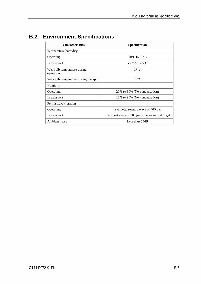
B.2 Environment Specifications
C144-E072-01EN B-5
B.2 Environment SpecificationsCharacteristics Specification
Temperature/humidity
Operating 10°C to 35°C
In transport -35°C to 65°C
Wet-bulb temperature duringoperation
26°C
Wet-bulb temperature during transport 46°C
Humidity
Operating 20% to 80% (No condensation)
In transport 10% to 90% (No condensation)
Permissible vibration
Operating Synthetic seismic wave of 400 gal
In transport Transport wave of 900 gal, sine wave of 400 gal
Ambient noise Less than 55dB

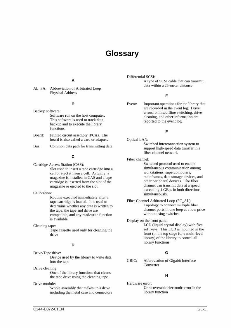
C144-E072-01EN GL-1
Glossary
A
AL_PA: Abbreviation of Arbitrated LoopPhysical Address
B
Backup software:Software run on the host computer.This software is used to track databackup and to execute the libraryfunctions.
Board: Printed circuit assembly (PCA). Theboard is also called a card or adapter.
Bus: Common data path for transmitting data
C
Cartridge Access Station (CAS):Slot used to insert a tape cartridge into acell or eject it from a cell. Actually, amagazine is installed in CAS and a tapecartridge is inserted from the slot of themagazine or ejected to the slot.
Calibration:Routine executed immediately after atape cartridge is loaded. It is used todetermine whether any data is written tothe tape, the tape and drive arecompatible, and any read/write functionis available.
Cleaning tape:Tape cassette used only for cleaning thedrive
D
Drive/Tape drive:Device used by the library to write datainto the tape
Drive cleaning:One of the library functions that cleansthe tape drive using the cleaning tape
Drive module:Whole assembly that makes up a driveincluding the metal case and connectors
Differential SCSI:A type of SCSI cable that can transmitdata within a 25-meter distance
E
Event: Important operations for the library thatare recorded in the event log. Driveerrors, online/offline switching, drivecleaning, and other information arereported to the event log.
F
Optical LAN:Switched interconnection system tosupport high-speed data transfer in afiber channel network
Fiber channel:Switched protocol used to enablesimultaneous communication amongworkstations, supercomputers,mainframes, data storage devices, andother peripheral devices. The fiberchannel can transmit data at a speedexceeding 1 GBps in both directionssimultaneously.
Fiber Channel Arbitrated Loop (FC_AL):Topology to connect multiple fiberchannel ports in one loop at a low pricewithout using switches
Display on the front panel:LCD (liquid crystal display) with fivesoft keys. This LCD is mounted in thefront (in the top stage for a multi-levellibrary) of the library to control alllibrary functions.
G
GBIC: Abbreviation of Gigabit InterfaceConverter
H
Hardware error:Unrecoverable electronic error in thelibrary function
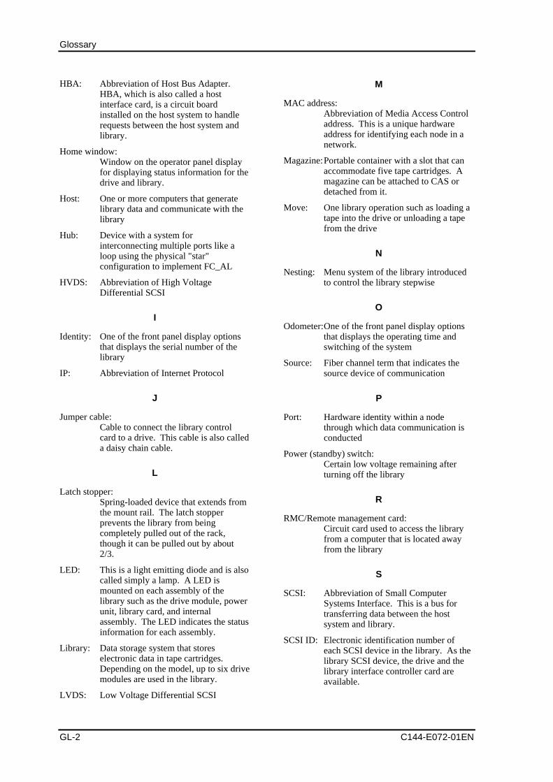
Glossary
GL-2 C144-E072-01EN
HBA: Abbreviation of Host Bus Adapter.HBA, which is also called a hostinterface card, is a circuit boardinstalled on the host system to handlerequests between the host system andlibrary.
Home window:Window on the operator panel displayfor displaying status information for thedrive and library.
Host: One or more computers that generatelibrary data and communicate with thelibrary
Hub: Device with a system forinterconnecting multiple ports like aloop using the physical "star"configuration to implement FC_AL
HVDS: Abbreviation of High VoltageDifferential SCSI
I
Identity: One of the front panel display optionsthat displays the serial number of thelibrary
IP: Abbreviation of Internet Protocol
J
Jumper cable:Cable to connect the library controlcard to a drive. This cable is also calleda daisy chain cable.
L
Latch stopper:Spring-loaded device that extends fromthe mount rail. The latch stopperprevents the library from beingcompletely pulled out of the rack,though it can be pulled out by about2/3.
LED: This is a light emitting diode and is alsocalled simply a lamp. A LED ismounted on each assembly of thelibrary such as the drive module, powerunit, library card, and internalassembly. The LED indicates the statusinformation for each assembly.
Library: Data storage system that storeselectronic data in tape cartridges.Depending on the model, up to six drivemodules are used in the library.
LVDS: Low Voltage Differential SCSI
M
MAC address:Abbreviation of Media Access Controladdress. This is a unique hardwareaddress for identifying each node in anetwork.
Magazine:Portable container with a slot that canaccommodate five tape cartridges. Amagazine can be attached to CAS ordetached from it.
Move: One library operation such as loading atape into the drive or unloading a tapefrom the drive
N
Nesting: Menu system of the library introducedto control the library stepwise
O
Odometer:One of the front panel display optionsthat displays the operating time andswitching of the system
Source: Fiber channel term that indicates thesource device of communication
P
Port: Hardware identity within a nodethrough which data communication isconducted
Power (standby) switch:Certain low voltage remaining afterturning off the library
R
RMC/Remote management card:Circuit card used to access the libraryfrom a computer that is located awayfrom the library
S
SCSI: Abbreviation of Small ComputerSystems Interface. This is a bus fortransferring data between the hostsystem and library.
SCSI ID: Electronic identification number ofeach SCSI device in the library. As thelibrary SCSI device, the drive and thelibrary interface controller card areavailable.
Glossary
C144-E072-01EN GL-3
SCSI element reservation:This enables the host to continueelement reservation even if the power isturned off or turned on. This function isusually used so that only a single hostcan securely access the slot or drive.
Single-end SCSI:One type of cable whose range islimited to short-distancecommunication
Soft error: Recoverable electronic error in thelibrary function. This type of error isrecorded in the soft error log.
Soft key: Five buttons at the bottom of the frontpanel display that are used forcommand execution on the display
Swap: Two related library operations such asmoving a tape from the slot to the driveand then moving it back to the slot
Switch: Device that provides (n x n)interconnection so that a completebandwidth for communication of a portwith any other port can be obtainedeven when other communications arebeing conducted.
T
Tape/Tape cartridge:Media used by the library to record datafrom the host computer
TCP/IP: Abbreviation of Transmission ControlProtocol/Internet Protocol
Terminator:Electronic device for stabilizing the bussignal by connecting to the SCSI busend
U
UTC: Abbreviation of Coordinated UniversalTime
W
Web-based library administrator:Explains the interface used to monitorand manage the library via the remotemanagement card on a network
Wide SCSI:68-pin connector. For practical use, thesingle-end and differential wide SCSIare available.

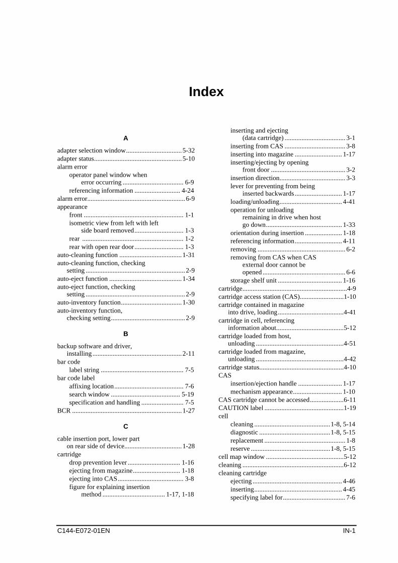
C144-E072-01EN IN-1
Index
A
adapter selection window.................................5-32adapter status....................................................5-10alarm error
operator panel window whenerror occurring .................................... 6-9
referencing information ........................... 4-24alarm error..........................................................6-9appearance
front ........................................................... 1-1isometric view from left with left
side board removed............................. 1-3rear ............................................................ 1-2rear with open rear door............................. 1-3
auto-cleaning function .....................................1-31auto-cleaning function, checking
setting ...........................................................2-9auto-eject function ...........................................1-34auto-eject function, checking
setting ...........................................................2-9auto-inventory function....................................1-30auto-inventory function,
checking setting............................................2-9
B
backup software and driver,installing .....................................................2-11
bar codelabel string ................................................. 7-5
bar code labelaffixing location......................................... 7-6search window ......................................... 5-19specification and handling ......................... 7-5
BCR .................................................................1-27
C
cable insertion port, lower parton rear side of device..................................1-28
cartridgedrop prevention lever ............................... 1-16ejecting from magazine............................ 1-18ejecting into CAS....................................... 3-8figure for explaining insertion
method ..................................... 1-17, 1-18
inserting and ejecting(data cartridge) .................................... 3-1
inserting from CAS .................................... 3-8inserting into magazine ............................ 1-17inserting/ejecting by opening
front door ............................................ 3-2insertion direction....................................... 3-3lever for preventing from being
inserted backwards ............................ 1-17loading/unloading..................................... 4-41operation for unloading
remaining in drive when hostgo down............................................. 1-33
orientation during insertion ...................... 1-18referencing information............................ 4-11removing .................................................... 6-2removing from CAS when CAS
external door cannot beopened ................................................. 6-6
storage shelf unit ...................................... 1-16cartridge..............................................................4-9cartridge access station (CAS)..........................1-10cartridge contained in magazine
into drive, loading.......................................4-41cartridge in cell, referencing
information about........................................5-12cartridge loaded from host,
unloading ....................................................4-51cartridge loaded from magazine,
unloading ....................................................4-42cartridge status..................................................4-10CAS
insertion/ejection handle .......................... 1-17mechanism appearance............................. 1-10
CAS cartridge cannot be accessed....................6-11CAUTION label ...............................................1-19cell
cleaning .............................................1-8, 5-14diagnostic ..........................................1-8, 5-15replacement ................................................ 1-8reserve ...............................................1-8, 5-15
cell map window ..............................................5-12cleaning ............................................................6-12cleaning cartridge
ejecting ..................................................... 4-46inserting.................................................... 4-45specifying label for..................................... 7-6
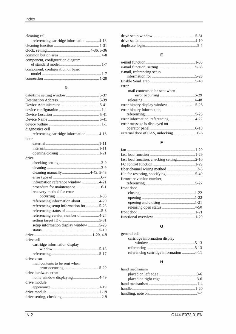
Index
IN-2 C144-E072-01EN
cleaning cellreferencing cartridge information.............4-13
cleaning function ............................................. 1-31clock, setting........................................... 4-36, 5-36common button area .......................................... 4-8component, configuration diagram
of standard model......................................... 1-7component, configuration of basic
model ........................................................... 1-7connection ....................................................... 1-20
D
date/time setting window................................. 5-37Destination Address......................................... 5-39Device Administrator ...................................... 5-41device configuration .......................................... 1-1Device Location .............................................. 5-41Device Name ................................................... 5-41device outline .................................................... 1-1diagnostics cell
referencing cartridge information.............4-16door
external .....................................................1-11internal......................................................1-11opening/closing ........................................1-21
drivechecking setting..........................................2-9cleaning ......................................................3-9cleaning manually............................4-43, 5-43error type of................................................6-7information reference window .................4-21procedure for maintenance .........................6-1recovery method for error
occurring ...........................................1-33referencing information about ..................4-20referencing setup information for .............5-23referencing status of ...................................5-8referencing version number of..................4-24setting target ID of....................................5-31setup information display window ...........5-23status.........................................................5-10
drive.......................................................... 1-20, 4-9drive cell
cartridge information displaywindow..............................................5-18
referencing................................................5-17drive error
mail contents to be sent whenerror occurring...................................5-29
drive hardware errorhome window displaying..........................4-49
drive moduleappearance................................................1-19
drive module.................................................... 1-19drive setting, checking....................................... 2-9
drive setup window.......................................... 5-31drive status ....................................................... 4-10duplicate login.................................................... 5-5
E
e-mail function................................................. 1-35e-mail function, setting .................................... 5-38e-mail, referencing setup
information for ........................................... 5-28Enable Send Trap............................................. 5-40error
mail contents to be sent whenerror occurring ...................................5-29
releasing....................................................4-48error history display window ........................... 5-25error history information,
referencing.................................................. 5-25error information, referencing.......................... 4-22error message is displayed on
operator panel............................................. 6-10external door of CAS, unlocking ....................... 6-6
F
fan .................................................................... 1-20fast load function ............................................. 1-29fast load function, checking setting.................. 2-10FC control function .......................................... 1-29fiber channel wiring method .............................. 2-5file for restoring, specifying............................. 5-49firmware version number,
referencing.................................................. 5-27front door
closing.......................................................1-22opening .....................................................1-22opening and closing ..................................1-21releasing open status .................................4-50
front door ......................................................... 1-21functional overview ......................................... 1-29
G
general cellcartridge information display
window ..............................................5-13referencing ................................................5-13referencing cartridge information .............4-11
H
hand mechanismplaced on left edge ......................................3-6placed on right edge....................................3-6
hand mechanism ................................................ 1-4handle............................................................... 1-20handling, note on................................................ 7-4
Index
C144-E072-01EN IN-3
hardware erroroperator panel window when
error occurring .................................... 6-8releasing................................................... 4-48
hardware error....................................................6-8hardware error drive
referencing information for...................... 4-23hardware error library
referencing information for...................... 4-22hardware error of drive
releasing................................................... 4-48hardware error of library
operator panel window whenerror occurring .................................... 6-8
releasing................................................... 4-48hardware error of library ....................................6-8hardware module..............................................1-27home window, configuration of .........................4-6host
checking setting ....................................... 2-11preparing installation ................................. 2-4
host interfacereferencing information about.................. 4-17referencing setup information for ............ 5-19setting information about ................ 4-28, 5-32setting window......................................... 5-33setup information display window........... 5-20
host interface informationreference windowAL connection/hard address being
set...................................................... 4-18fabric connection being set ...................... 4-18
host WWPNchecking setting ......................................... 2-9setting....................................................... 4-31setting window......................................... 4-32
host WWPN list, registering ............................4-33host WWPN permitted for each
adapter, referencing ....................................4-19
I
icon area.............................................................4-7installation, checking .......................................2-11interface ...........................................................1-20interface card....................................................1-27internal door
being opened............................................ 1-24closing...................................................... 1-24opening .................................................... 1-24opening and closing ................................. 1-23
internal door .....................................................1-23inventory function............................................1-30inventory, making ............................................4-52
L
label affixing, note on................................. 7-4, 7-6label string, specifying .......................................7-5LED section, device rear view................ 1-27, 1-28library
checking setting.......................................... 2-9connecting .................................................. 2-5each component of ..................................... 1-7error type of................................................ 6-8host do not detect ..................................... 6-10installation condition for ............................ 2-1installation space required for .................... 2-2performance.............................................. 6-12procedure for maintenance ......................... 6-1recovery method for error
occurring ........................................... 1-33referencing information...................4-11, 5-12referencing setup information for....4-20, 5-22referencing status of ................................... 4-9referencing version number of ................. 4-24setting information ....... 4-28, 4-34, 5-32, 5-34setup information display window ........... 5-22status........................................................... 5-9
library alarm error ..............................................6-9library error
mail contents when erroroccurring ........................................... 5-29
library hardware errorhome window displaying ......................... 4-48
library performance, poor.................................6-12library power is not on......................................6-10library setting, checking .....................................2-9login....................................................................5-4login method.......................................................5-3Loop ID, setting................................................4-28LOOP ID/ALPA correspondence
table ............................................................4-27LUN, referencing .............................................4-17
M
magazineejection method ........................................ 1-15figure for explaining mechanism.............. 1-16inserting from CAS .................................. 1-11insertion method..............................1-13, 1-14insertion/ejection port............................... 1-11opening door............................................. 4-39
magazine ..........................................................1-16magazine cell
cartridge information displaywindow.............................................. 5-16
referencing................................................ 5-16referencing cartridge information............. 4-12
main area ............................................................4-6
Index
IN-4 C144-E072-01EN
maintenance....................................................... 6-1manual cleaning function ................................ 1-32manual cleaning operation window................. 5-44manual load function ....................................... 1-31media area, deleting........................................... 7-6menu window, configuration of......................... 4-6model element, configuration list of.................. 1-9model, configuration and upgrade
pattern for each ............................................ 1-9
N
networkreferencing setup information for ....4-22, 5-24setting information about.................4-35, 5-35setup information display window ...........5-24
new ID, host computer cannotidentify....................................................... 6-10
O
operator panelbeing inoperative ......................................6-12not being displayed...................................6-12overview of.................................................4-1
overview ............................................................ 1-1
P
picker mechanism.............................................. 3-5positioning projection...................................... 1-11power
method for power-off .................................2-8method for power-on ..................................2-7switch (power-off)......................................2-8
power supply ................................................... 1-27power to unit.................................................... 3-10power-on test failure........................................ 6-10
R
RCIbeing not used.............................................2-8being used............................................2-7, 2-8not being used.............................................2-7
reader pin, note on ............................................. 7-4rear door
being opened ............................................1-26closing ......................................................1-26opening.....................................................1-26opening and closing..................................1-25
rear door .......................................................... 1-25recovery method
for drive error occurring ...........................1-33for library error occurring.........................1-33
recovery, function for ...................................... 1-33relative position flag ........................................ 1-20
remote panelchecking setting ........................................2-10frame configuration.....................................5-6function.....................................................1-34menu tree ....................................................5-7starting window ..........................................5-2
remote panel..................................................... 6-13reserve cell
referencing cartridge information .............4-14reset button, selecting....................................... 4-49robot
appearance ..................................................1-6part requiring grease in ...............................3-7removing cartridge from hand
mechanism for failure ..........................6-2robot................................................................... 1-4
S
screen saver, setting ......................................... 4-38server, turning on ............................................. 3-11setup information
restoring ....................................................5-49save window .............................................5-46saving........................................................5-46
setup information beingdownloaded, confirming............................. 5-47
SMTP Address ................................................. 5-39SNMP
agent, setting .............................................5-40function.....................................................1-36referencing setup information for .............5-30
SNMP traptest start window .......................................5-50test, executing ...........................................5-50transmission completion window .............5-51
Source Address ................................................ 5-39special cell.......................................................... 1-8status, explanation of ....................................... 5-14stopper for drop prevention.............................. 1-20subtitle area ........................................................ 4-6
T
tape cartridgeenvironment condition for storing ..............7-3environment condition for
transporting..........................................7-3handling ......................................................7-3precaution for using ....................................7-7replacement period......................................7-2
tape is stuck...................................................... 6-11target ID
checking setting ..........................................2-9referencing ................................................4-17setting.............................................. 4-25, 4-28
Index
C144-E072-01EN IN-5
time and date, checking setting ........................2-10title area..............................................................4-6touch-panel operation.........................................4-1trace file operation ...........................................5-45transport handle................................................1-16transport metal bracket, removing......................2-3transportation, note on .......................................7-3Trap Destination IP Address ............................5-40troubleshooting ................................................6-10
U
ultrium cartridge information.............................7-1upgrade pattern
A20 ............................................................ 1-9A32 ............................................................ 1-9
V
volume area, specifying......................................7-6warning message ..............................................5-10
W
windowconfiguration .............................................. 4-6home........................................................... 4-3initialization................................................ 4-3menu........................................................... 4-4type............................................................. 4-3
writing to tape failure .......................................6-11

FUJITSU LIMITED
READER’S COMMENT FORMYour comments or suggestions on this document are cordially solicited. For any comments and suggestionsyou may have, please complete and submit this form to your FUJITSU representative. The comments andsuggestions will be used in planning future editions. Thank you for your cooperation.
Date issued: Manual name:
Name: Company or organization: Manual code: Address: Comments:
Page Line Comments
Reply requested: Yes No
Please evaluate overall quality of this manual by marking (√) in the appropriate boxes.Good Fair Poor Good Fair Poor Good Fair
PoorOrganization: Use of examples: Legibility: Accuracy: Index coverage: Handiness/Binding: Clarity: Cross referencing: (Others): Figures & tables: General appearance: Technical level: Too high Appropriate Too low Overall rating ofthis publication: Good Fair Poor
FOR FUJITSU USE
Overseas office: Person in charge:
Note) Local representative should pass this form to the section in charge of distribution in FUJITSU.
Reply
ETERNUSLT160Tape LibraryC144-E072-01EN
By