Embed Size (px)
Citation preview
Estimation of the Air-Demand, Flame Height, and Radiation Load from Low-Profile Flare using ISIS-3D
J.D. Smith, Ph.D. and A. Suo-Ahttila, Ph.D.,Alion Science and Technology, Owasso, Oklahoma, USA
and
S. Smith and J. ModiZeeco Inc., Broken Arrow, Oklahoma, USA
American – Japanese Flame Research Committees International Symposium Advances in Combustion Technology: Improving the Environment and Energy Efficiency
Marriott Waikoloa, Hawaii - Oct. 22 –24, 2007
American – Japanese Flame Research Committees International Symposium Advances in Combustion Technology: Improving the Environment and Energy Efficiency
Marriott Waikoloa, Hawaii - Oct. 22 –24, 2007
Slide 2
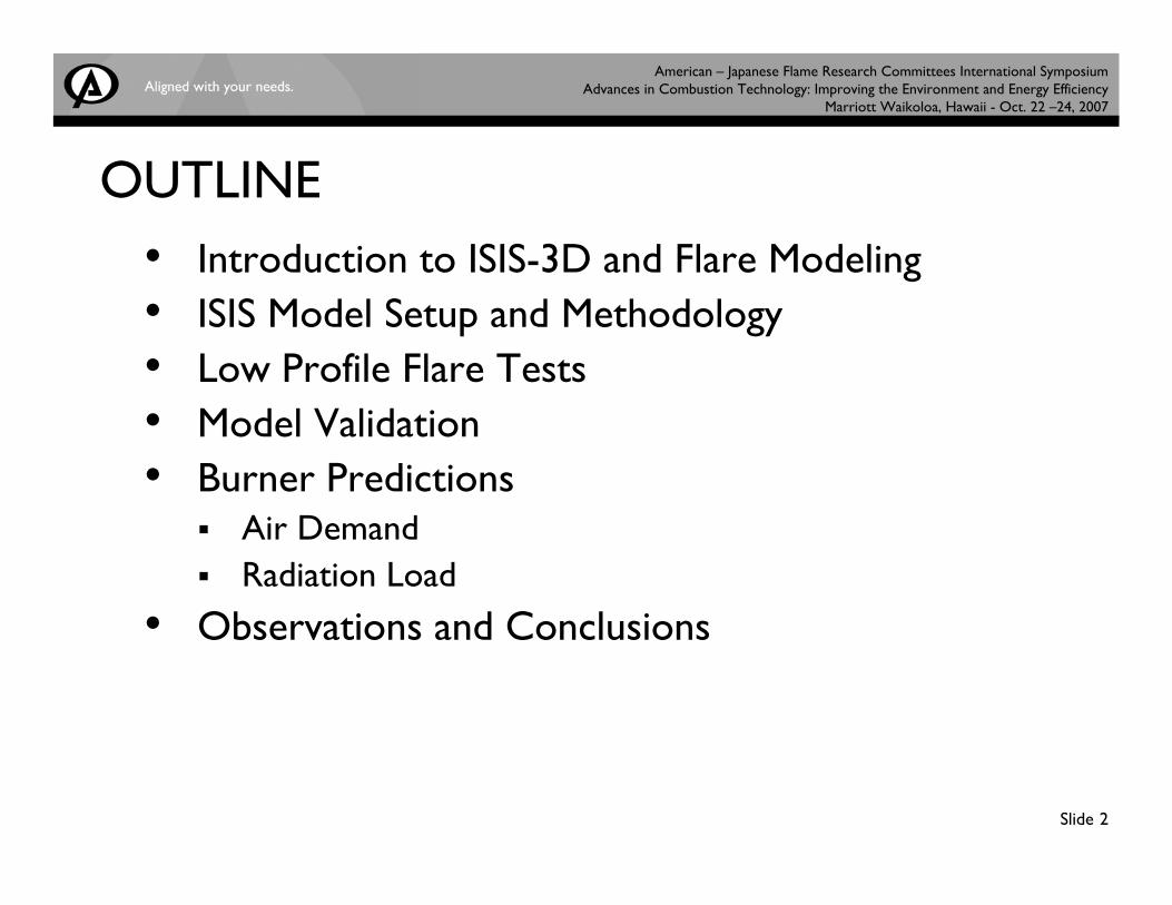
OUTLINE• Introduction to ISIS-3D and Flare Modeling• ISIS Model Setup and Methodology• Low Profile Flare Tests • Model Validation• Burner Predictions
Air DemandRadiation Load
• Observations and Conclusions
American – Japanese Flame Research Committees International Symposium Advances in Combustion Technology: Improving the Environment and Energy Efficiency
Marriott Waikoloa, Hawaii - Oct. 22 –24, 2007
Slide 3
ISIS-3D General Comments• Based on Computational Fluid Dynamics with radiative heat
transfer and combustion chemistry• Linked model is capable of simulating complex, three-dimensional
objects engulfed in fires• Provide reasonably accurate estimates of the total heat transfer
to objects from large fires• Predict general characteristics of temperature distribution in
object• Accurately assess impact of variety of risk scenarios (wind, %
flame coverage, thermal fatigue for given geometry, etc.) • Reasonable CPU time requirements on “standard” desktop
LINUX workstation
American – Japanese Flame Research Committees International Symposium Advances in Combustion Technology: Improving the Environment and Energy Efficiency
Marriott Waikoloa, Hawaii - Oct. 22 –24, 2007
Slide 4
ISIS-3D Trade-Offs
• Sacrifice generality (large fires only) in favor of quick turnaround time and quantitative accuracy
• Reaction rate and radiation heat transfer models apply only to large fires
• Models intended to make ISIS-3D predictions “good-enough” for industrial use
American – Japanese Flame Research Committees International Symposium Advances in Combustion Technology: Improving the Environment and Energy Efficiency
Marriott Waikoloa, Hawaii - Oct. 22 –24, 2007
Slide 5
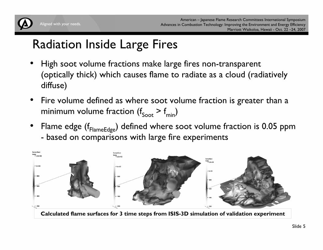
Radiation Inside Large Fires• High soot volume fractions make large fires non-transparent
(optically thick) which causes flame to radiate as a cloud (radiatively diffuse)
• Fire volume defined as where soot volume fraction is greater than a minimum volume fraction (fSoot > fmin)
• Flame edge (fFlameEdge) defined where soot volume fraction is 0.05 ppm - based on comparisons with large fire experiments
Calculated flame surfaces for 3 time steps from ISIS-3D simulation of validation experiment
American – Japanese Flame Research Committees International Symposium Advances in Combustion Technology: Improving the Environment and Energy Efficiency
Marriott Waikoloa, Hawaii - Oct. 22 –24, 2007
Slide 6
• When fSoot < fFlameEdge => outside “flame” (participating medium considered)
• View factors from fire to un-engulfed surfaces calculated at each time step (include attenuation by flames)
• Radiation view factor from object surface to surroundings calculated at each time step
• εFireSurface = 1 (fire is black body radiator)
• Radiation from fire surface to surroundings assumes Tsurround = constant
Radiation Outside of Large Fires
American – Japanese Flame Research Committees International Symposium Advances in Combustion Technology: Improving the Environment and Energy Efficiency
Marriott Waikoloa, Hawaii - Oct. 22 –24, 2007
Slide 7
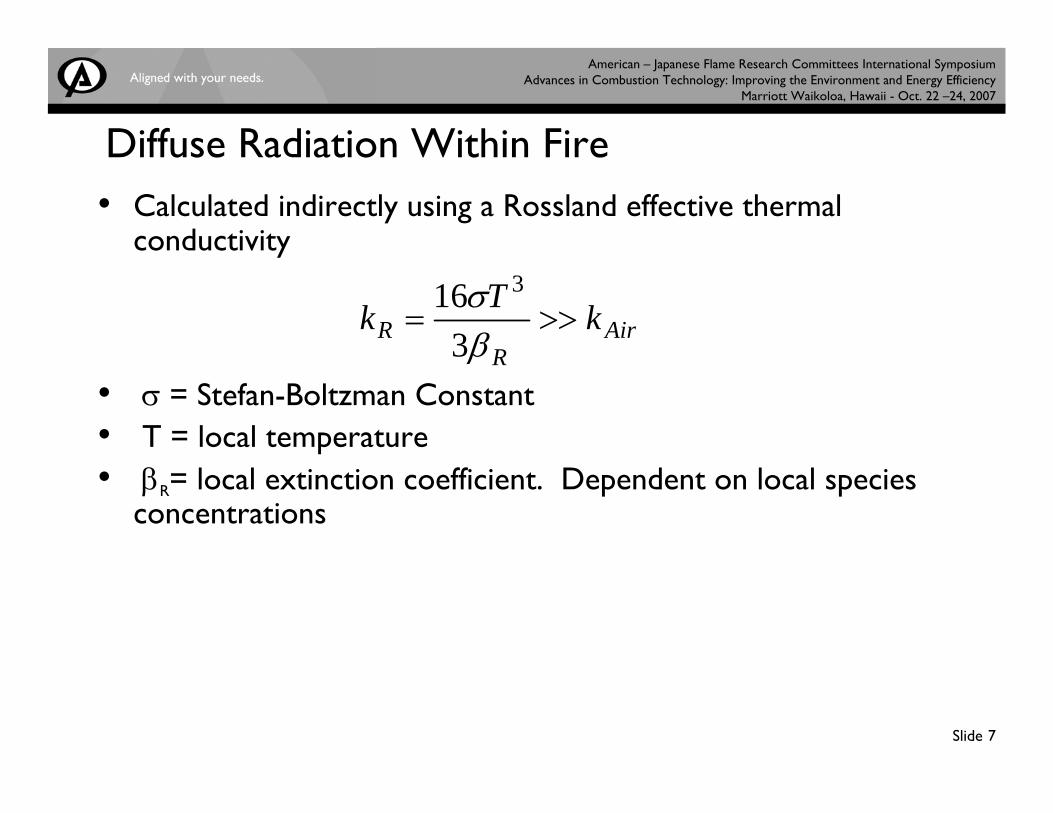
Diffuse Radiation Within Fire• Calculated indirectly using a Rossland effective thermal
conductivity
• σ = Stefan-Boltzman Constant• T = local temperature• βR= local extinction coefficient. Dependent on local species
concentrations
AirR
R kTk >>=βσ
316 3
American – Japanese Flame Research Committees International Symposium Advances in Combustion Technology: Improving the Environment and Energy Efficiency
Marriott Waikoloa, Hawaii - Oct. 22 –24, 2007
Slide 8
Combustion Model• Variant of Said et al. (1997) turbulent flame model• Relevant Species (model includes relevant reactions)
F = Fuel Vapor (from evaporation or flare tip) O2 = Oxygen PC = H20(v) + CO2
C = Radiating Carbon Soot IS = Non-radiating Intermediate Species
• Eddy dissipation effects and local equivalence ratio effects• Reactions based on Arrhenius kinetics
• C and TA determined for all reactions
American – Japanese Flame Research Committees International Symposium Advances in Combustion Technology: Improving the Environment and Energy Efficiency
Marriott Waikoloa, Hawaii - Oct. 22 –24, 2007
Slide 9
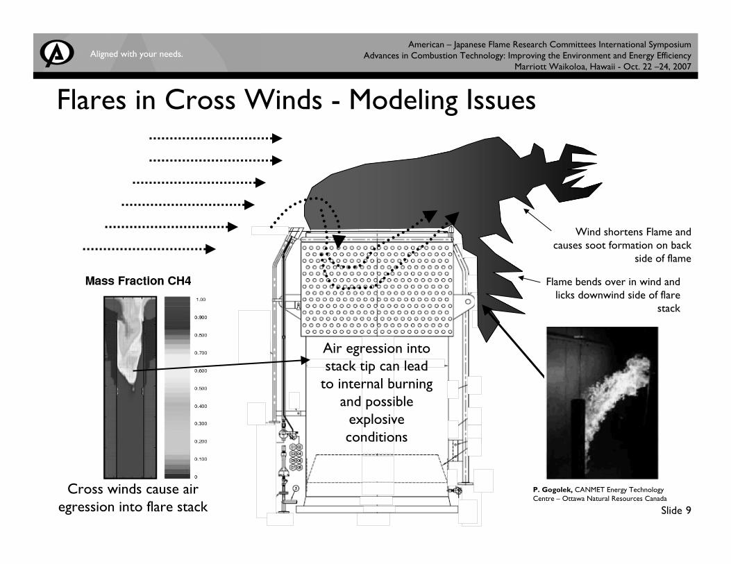
Air egression into stack tip can lead
to internal burning and possible
explosive conditions
Flares in Cross Winds - Modeling Issues
Cross winds cause air egression into flare stack
Flame bends over in wind and licks downwind side of flare
stack
P. Gogolek, CANMET Energy Technology Centre – Ottawa Natural Resources Canada
Wind shortens Flame and causes soot formation on back
side of flame
American – Japanese Flame Research Committees International Symposium Advances in Combustion Technology: Improving the Environment and Energy Efficiency
Marriott Waikoloa, Hawaii - Oct. 22 –24, 2007
Slide 10
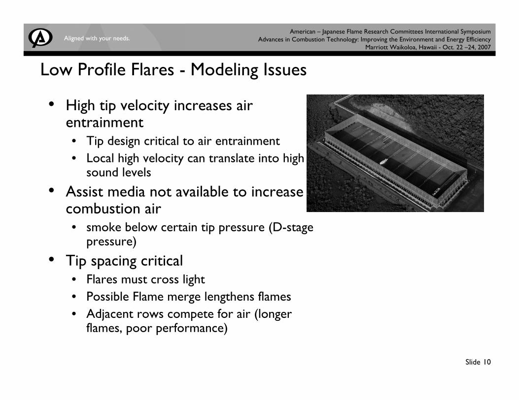
Low Profile Flares - Modeling Issues
• High tip velocity increases air entrainment• Tip design critical to air entrainment• Local high velocity can translate into high
sound levels
• Assist media not available to increase combustion air• smoke below certain tip pressure (D-stage
pressure)
• Tip spacing critical• Flares must cross light• Possible Flame merge lengthens flames• Adjacent rows compete for air (longer
flames, poor performance)
American – Japanese Flame Research Committees International Symposium Advances in Combustion Technology: Improving the Environment and Energy Efficiency
Marriott Waikoloa, Hawaii - Oct. 22 –24, 2007
Slide 11
Approach to Modeling Full Flare Fields
• Model Single Burner Test• Perform Calibration Tests• Calibrate Soot Yield and Reaction Parameters for Test Fuel• Predict flame shape and size
• Model Multi-Burner Test• Perform Radiation Calibration Tests• Check Tip/Row Spacing• Predict flame shape and size
• Model Full Flare Field• Use Calibrated Soot Yield and Radiation Models• Predict Flare Performance (Smoke Production/Air Demand)• Predict Radiation Load on Wind Fence
American – Japanese Flame Research Committees International Symposium Advances in Combustion Technology: Improving the Environment and Energy Efficiency
Marriott Waikoloa, Hawaii - Oct. 22 –24, 2007
Slide 12
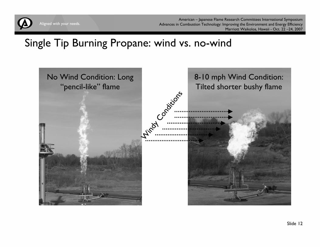
Single Tip Burning Propane: wind vs. no-wind
No Wind Condition: Long “pencil-like” flame
8-10 mph Wind Condition:Tilted shorter bushy flame
Wind
y Con
ditio
ns
American – Japanese Flame Research Committees International Symposium Advances in Combustion Technology: Improving the Environment and Energy Efficiency
Marriott Waikoloa, Hawaii - Oct. 22 –24, 2007
Slide 13
Modeling Low Profile Flare Test
• Propane injected as mass, momentum and species sources
• Fuel Mol wt – 44 (C3H8)
• Tip elevation – 2.0 m (6.5 ft)
• Tip Geometry Provide by Client
• Test Conditions for Propane Mass Flow = 0.46 kg/s (3,651 #/hr)
• Flame height determined by fuel and soot burnout
• Air inflow calculated implicitly from pressure boundary conditions
• Radiation Flux calibrated from measured data at two locations
American – Japanese Flame Research Committees International Symposium Advances in Combustion Technology: Improving the Environment and Energy Efficiency
Marriott Waikoloa, Hawaii - Oct. 22 –24, 2007
Slide 14
Single Burner Flare Model
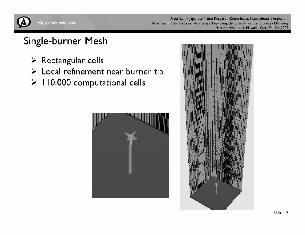
• 6 X 6 X 26 m physical domain• Flare Tip located 2 m above ground level• Turbulence and Arrhenius kinetics Included for fuel gas
Reaction Parameters adjusted to match observed flame characteristicsSoot Yield matched flame height (i.e., soot burnout)
• Flare Movies for no wind, 3m/s (7mph) wind conditions• Predicted results for Air demand and Radiation loss from flame
determined
American – Japanese Flame Research Committees International Symposium Advances in Combustion Technology: Improving the Environment and Energy Efficiency
Marriott Waikoloa, Hawaii - Oct. 22 –24, 2007
Slide 15
Single-burner Mesh
Rectangular cellsLocal refinement near burner tip110,000 computational cells
American – Japanese Flame Research Committees International Symposium Advances in Combustion Technology: Improving the Environment and Energy Efficiency
Marriott Waikoloa, Hawaii - Oct. 22 –24, 2007
Slide 16
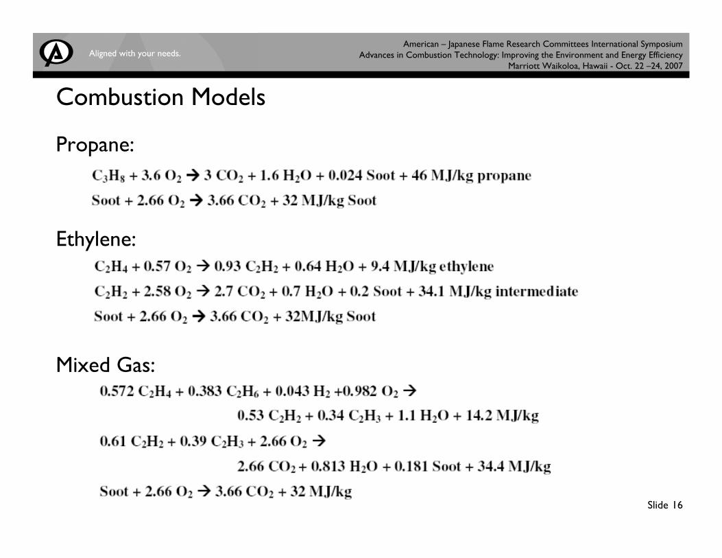
Combustion Models
Propane:
Ethylene:
Mixed Gas:
American – Japanese Flame Research Committees International Symposium Advances in Combustion Technology: Improving the Environment and Energy Efficiency
Marriott Waikoloa, Hawaii - Oct. 22 –24, 2007
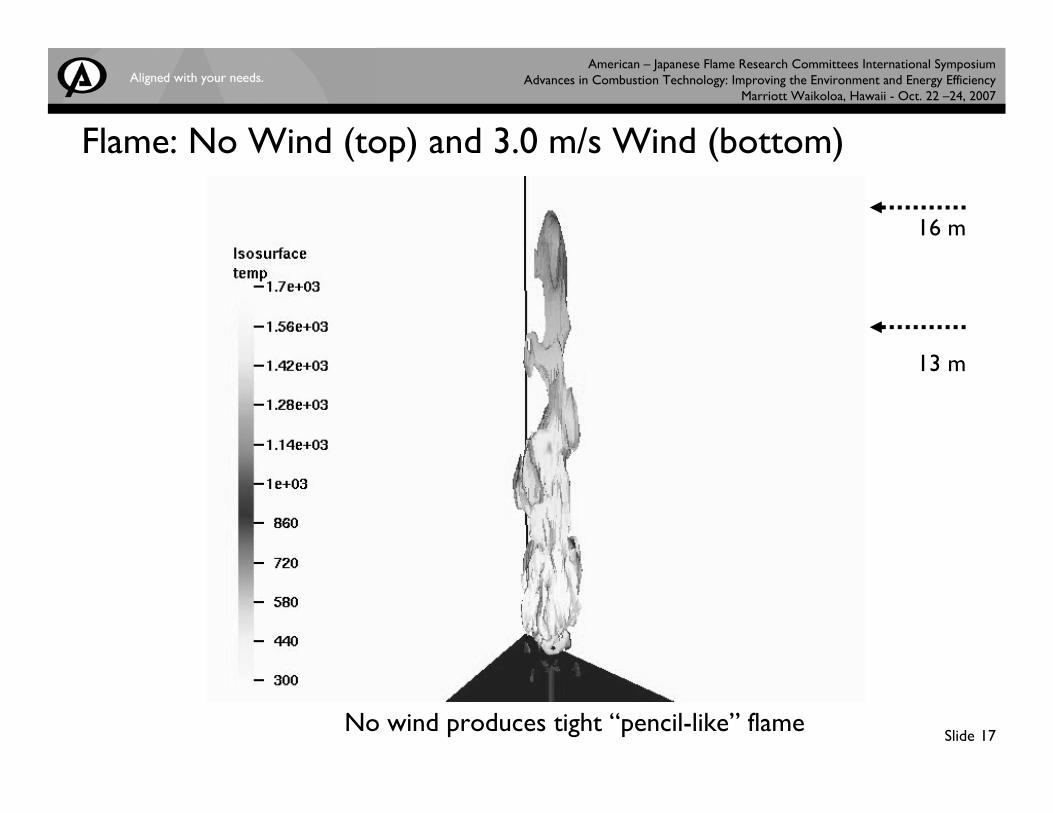
Slide 17No wind produces tight “pencil-like” flame
Flame: No Wind (top) and 3.0 m/s Wind (bottom)
13 m
16 m
American – Japanese Flame Research Committees International Symposium Advances in Combustion Technology: Improving the Environment and Energy Efficiency
Marriott Waikoloa, Hawaii - Oct. 22 –24, 2007
Slide 18
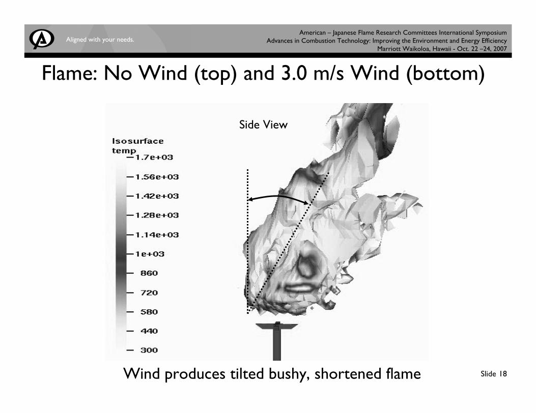
Flame: No Wind (top) and 3.0 m/s Wind (bottom)
Wind produces tilted bushy, shortened flame
Side View
American – Japanese Flame Research Committees International Symposium Advances in Combustion Technology: Improving the Environment and Energy Efficiency
Marriott Waikoloa, Hawaii - Oct. 22 –24, 2007
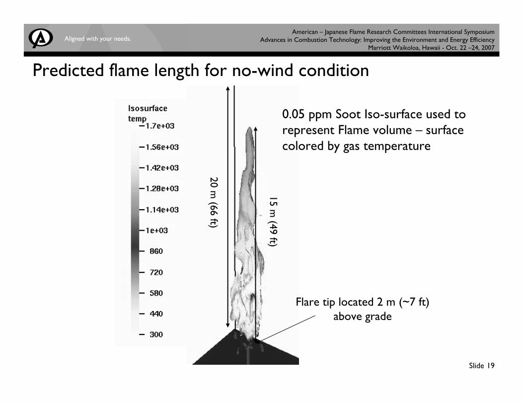
Slide 19
15 m (49 ft)
20 m (66 ft)
Flare tip located 2 m (~7 ft) above grade
0.05 ppm Soot Iso-surface used to represent Flame volume – surface colored by gas temperature
Predicted flame length for no-wind condition
American – Japanese Flame Research Committees International Symposium Advances in Combustion Technology: Improving the Environment and Energy Efficiency
Marriott Waikoloa, Hawaii - Oct. 22 –24, 2007
Slide 20
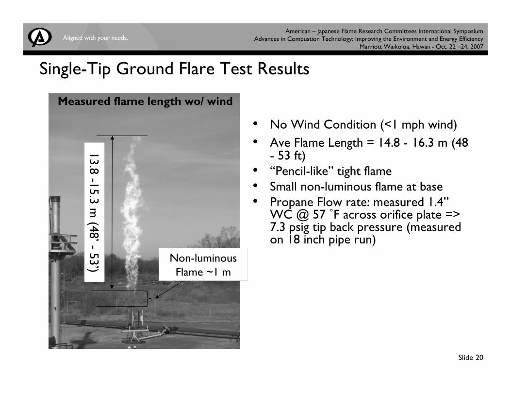
Single-Tip Ground Flare Test Results
Measured flame length wo/ wind
13.8 -15.3 m (48’-
53’)
• No Wind Condition (<1 mph wind)• Ave Flame Length = 14.8 - 16.3 m (48
- 53 ft)• “Pencil-like” tight flame• Small non-luminous flame at base• Propane Flow rate: measured 1.4”
WC @ 57 ˚F across orifice plate => 7.3 psig tip back pressure (measured on 18 inch pipe run)
Non-luminous Flame ~1 m
American – Japanese Flame Research Committees International Symposium Advances in Combustion Technology: Improving the Environment and Energy Efficiency
Marriott Waikoloa, Hawaii - Oct. 22 –24, 2007
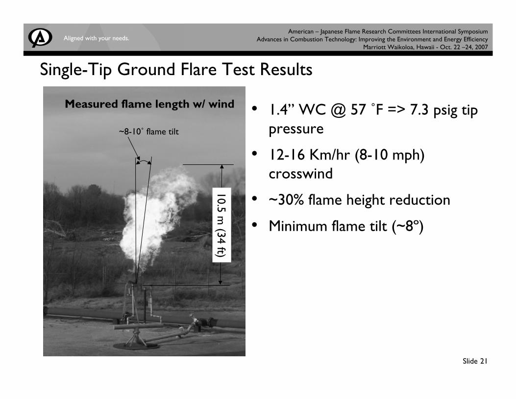
Slide 21
10.5 m (34 ft)
~8-10˚ flame tilt
Single-Tip Ground Flare Test Results
Measured flame length w/ wind • 1.4” WC @ 57 ˚F => 7.3 psig tip pressure
• 12-16 Km/hr (8-10 mph) crosswind
• ~30% flame height reduction
• Minimum flame tilt (~8º)
American – Japanese Flame Research Committees International Symposium Advances in Combustion Technology: Improving the Environment and Energy Efficiency
Marriott Waikoloa, Hawaii - Oct. 22 –24, 2007
Slide 22
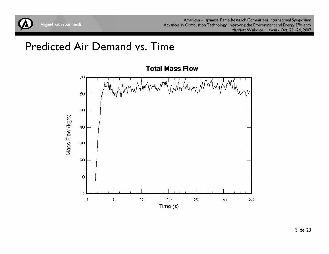
Model Used to Predict Flare Air Demand
• Based upon total mass flow through a 3.6 m square plane located 20 m height above flare
• Predicted flame height is 17 m above ground (15 m flame length)• Predicted 60 kg/sec air demand by flame• Total air inflow through all walls around computational domain is
100 kg/sec
American – Japanese Flame Research Committees International Symposium Advances in Combustion Technology: Improving the Environment and Energy Efficiency
Marriott Waikoloa, Hawaii - Oct. 22 –24, 2007
Slide 23
Predicted Air Demand vs. Time
American – Japanese Flame Research Committees International Symposium Advances in Combustion Technology: Improving the Environment and Energy Efficiency
Marriott Waikoloa, Hawaii - Oct. 22 –24, 2007
Slide 24
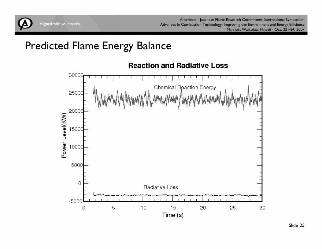
Model Used to Predict Flame Radiation Loss
• Radiation Depends upon Soot, CO2, H2O Concentration in Flame and Flame Size
• Soot yield from hydrocarbon assumed constant for propane• Predicted approx 3 MW radiation loss from 22 MW Flame or
13.6% heat loss
American – Japanese Flame Research Committees International Symposium Advances in Combustion Technology: Improving the Environment and Energy Efficiency
Marriott Waikoloa, Hawaii - Oct. 22 –24, 2007
Slide 25
Predicted Flame Energy Balance
American – Japanese Flame Research Committees International Symposium Advances in Combustion Technology: Improving the Environment and Energy Efficiency
Marriott Waikoloa, Hawaii - Oct. 22 –24, 2007
Slide 26
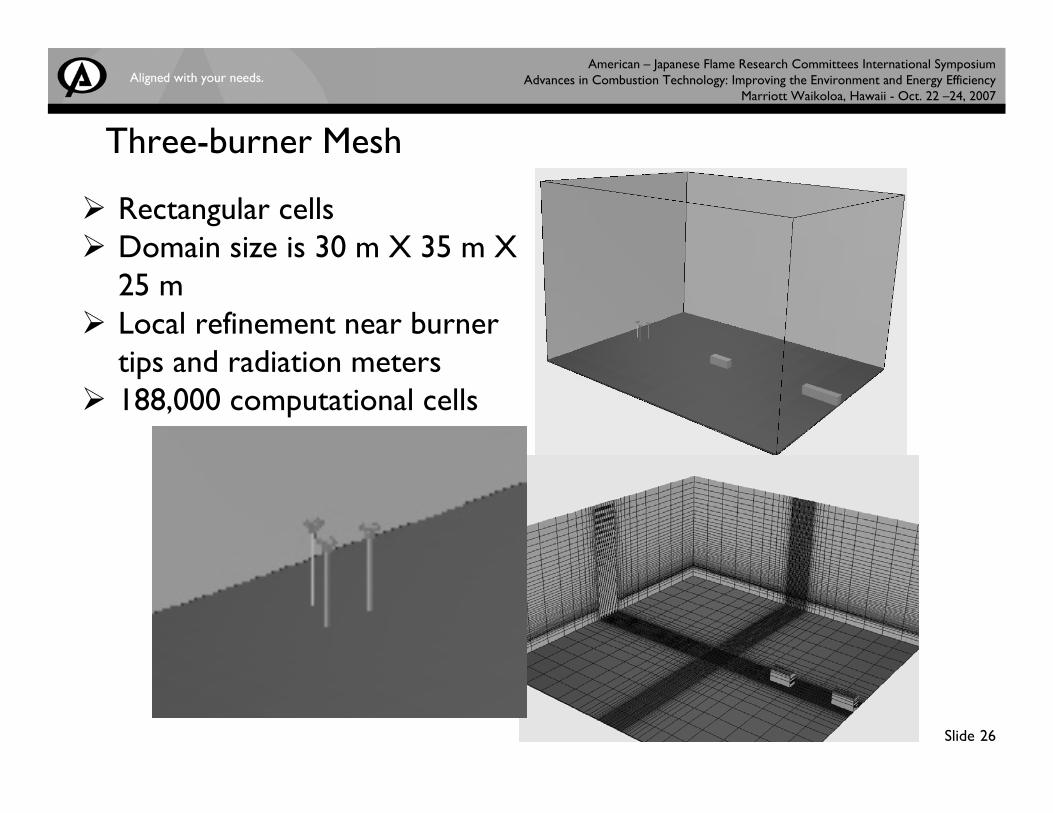
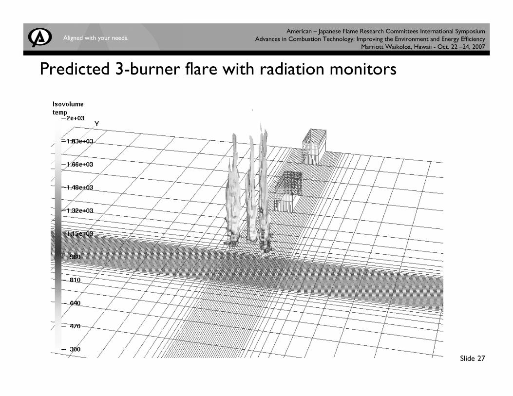
Three-burner Mesh
Rectangular cellsDomain size is 30 m X 35 m X 25 mLocal refinement near burner tips and radiation meters188,000 computational cells
American – Japanese Flame Research Committees International Symposium Advances in Combustion Technology: Improving the Environment and Energy Efficiency
Marriott Waikoloa, Hawaii - Oct. 22 –24, 2007
Slide 27
Predicted 3-burner flare with radiation monitors
American – Japanese Flame Research Committees International Symposium Advances in Combustion Technology: Improving the Environment and Energy Efficiency
Marriott Waikoloa, Hawaii - Oct. 22 –24, 2007
Slide 28
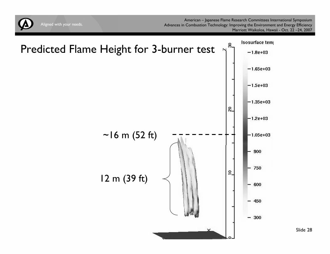
~16 m (52 ft)
Predicted Flame Height for 3-burner test
12 m (39 ft)
American – Japanese Flame Research Committees International Symposium Advances in Combustion Technology: Improving the Environment and Energy Efficiency
Marriott Waikoloa, Hawaii - Oct. 22 –24, 2007
Slide 29
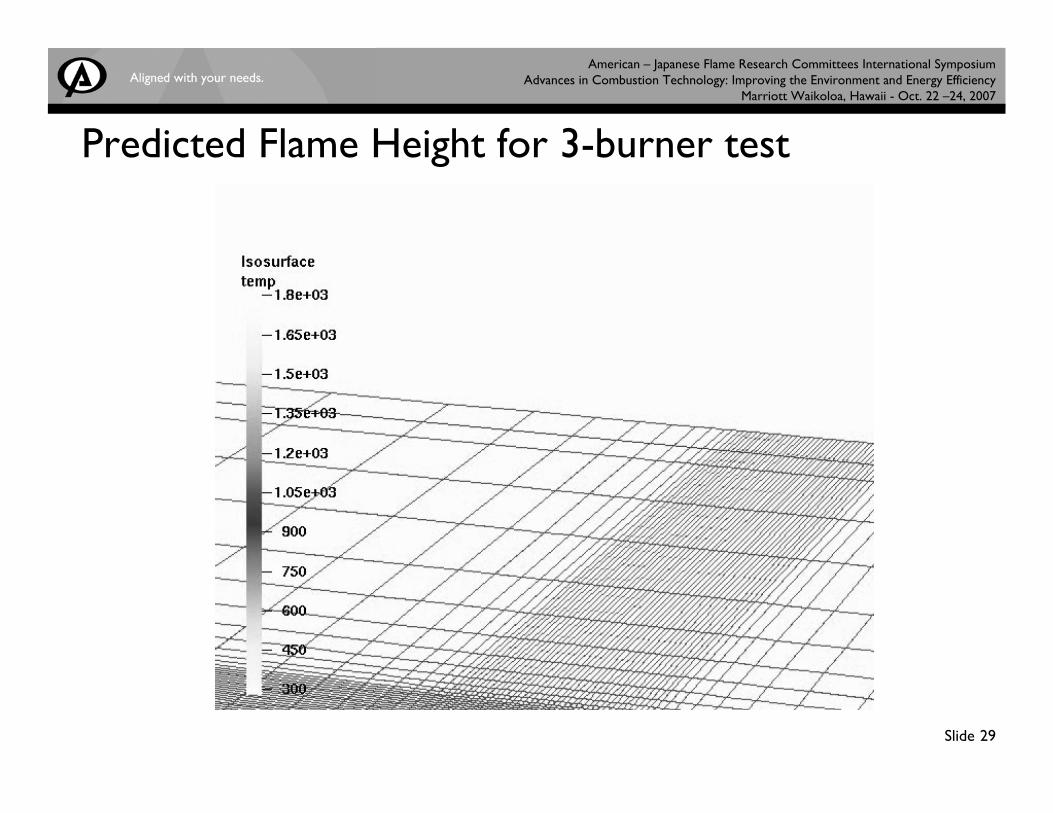
Predicted Flame Height for 3-burner test
American – Japanese Flame Research Committees International Symposium Advances in Combustion Technology: Improving the Environment and Energy Efficiency
Marriott Waikoloa, Hawaii - Oct. 22 –24, 2007
Slide 30
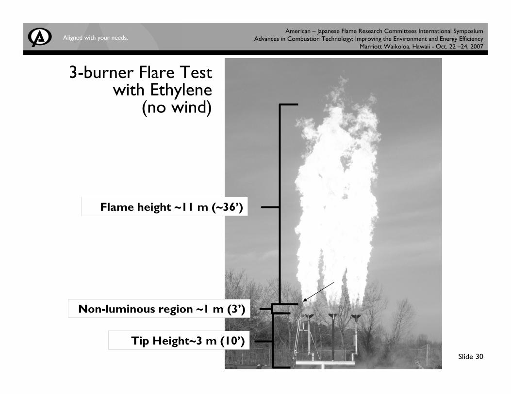
3-burner Flare Test with Ethylene
(no wind)
Tip Height~3 m (10’)
Non-luminous region ~1 m (3’)
Flame height ~11 m (~36’)
American – Japanese Flame Research Committees International Symposium Advances in Combustion Technology: Improving the Environment and Energy Efficiency
Marriott Waikoloa, Hawaii - Oct. 22 –24, 2007
Slide 31
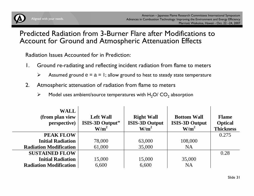
Predicted Radiation from 3-Burner Flare after Modifications to Account for Ground and Atmospheric Attenuation Effects
Radiation Issues Accounted for in Prediction:
1. Ground re-radiating and reflecting incident radiation from flame to meters
Assumed ground e = a = 1; allow ground to heat to steady state temperature
2. Atmospheric attenuation of radiation from flame to meters
Model uses ambient/source temperatures with H2O/ CO2 absorption
WALL (from plan view
perspective)
Left Wall ISIS-3D Output”
W/m2
Right Wall ISIS-3D Output
W/m2
Bottom Wall ISIS-3D Output
W/m2
Flame Optical
Thickness PEAK FLOW
Initial Radiation Radiation Modification
78,000 61,000
63,000 35,000
108,000
NA
0.275
SUSTAINED FLOW Initial Radiation
Radiation Modification
15,000 6,600
15,000 6,600
35,000
NA
0.28
American – Japanese Flame Research Committees International Symposium Advances in Combustion Technology: Improving the Environment and Energy Efficiency
Marriott Waikoloa, Hawaii - Oct. 22 –24, 2007
Slide 32
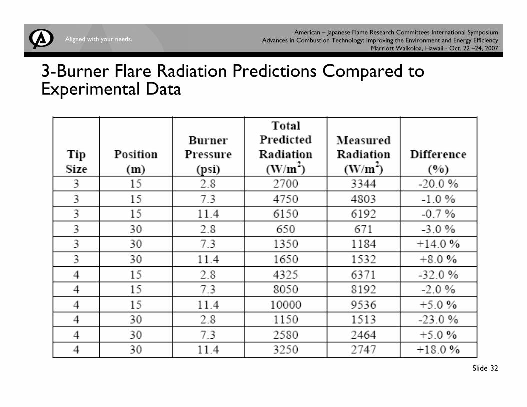
3-Burner Flare Radiation Predictions Compared to Experimental Data
American – Japanese Flame Research Committees International Symposium Advances in Combustion Technology: Improving the Environment and Energy Efficiency
Marriott Waikoloa, Hawaii - Oct. 22 –24, 2007
Slide 33
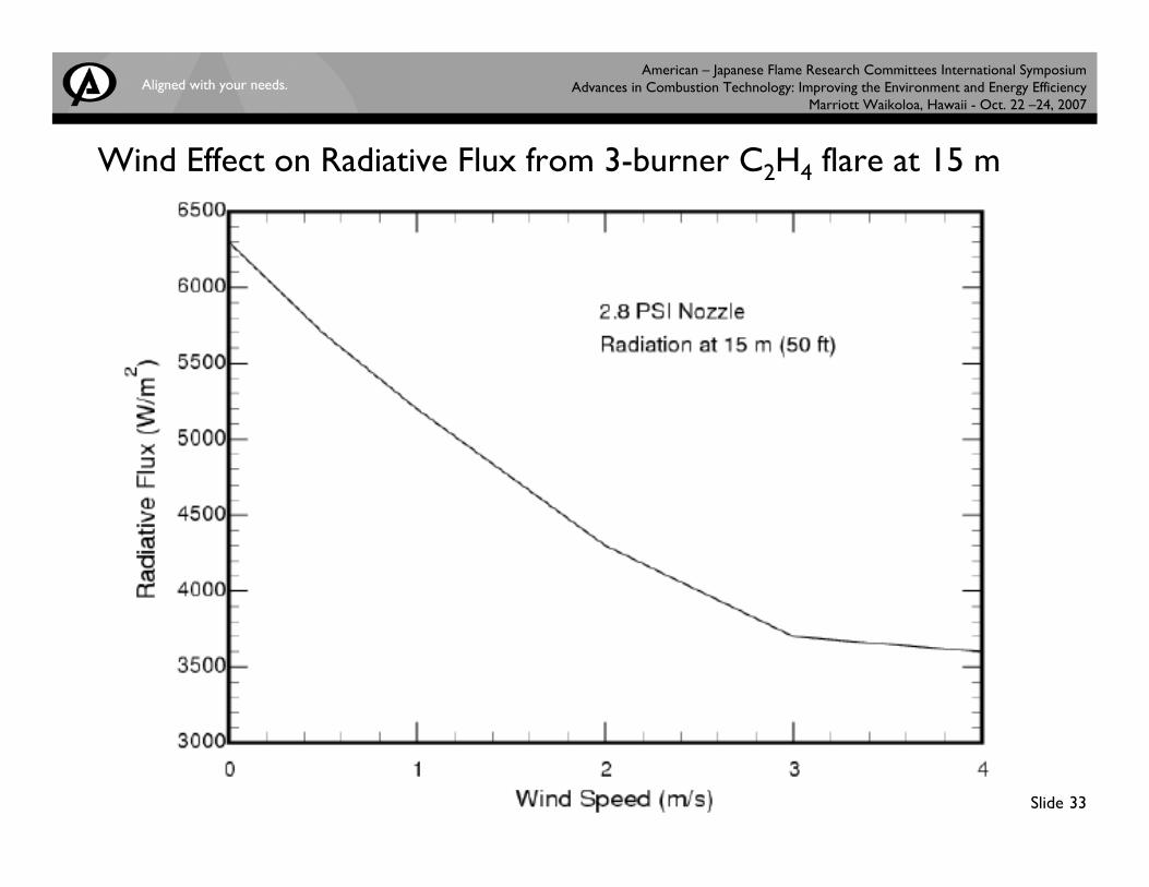
Wind Effect on Radiative Flux from 3-burner C2H4 flare at 15 m
American – Japanese Flame Research Committees International Symposium Advances in Combustion Technology: Improving the Environment and Energy Efficiency
Marriott Waikoloa, Hawaii - Oct. 22 –24, 2007
Slide 34
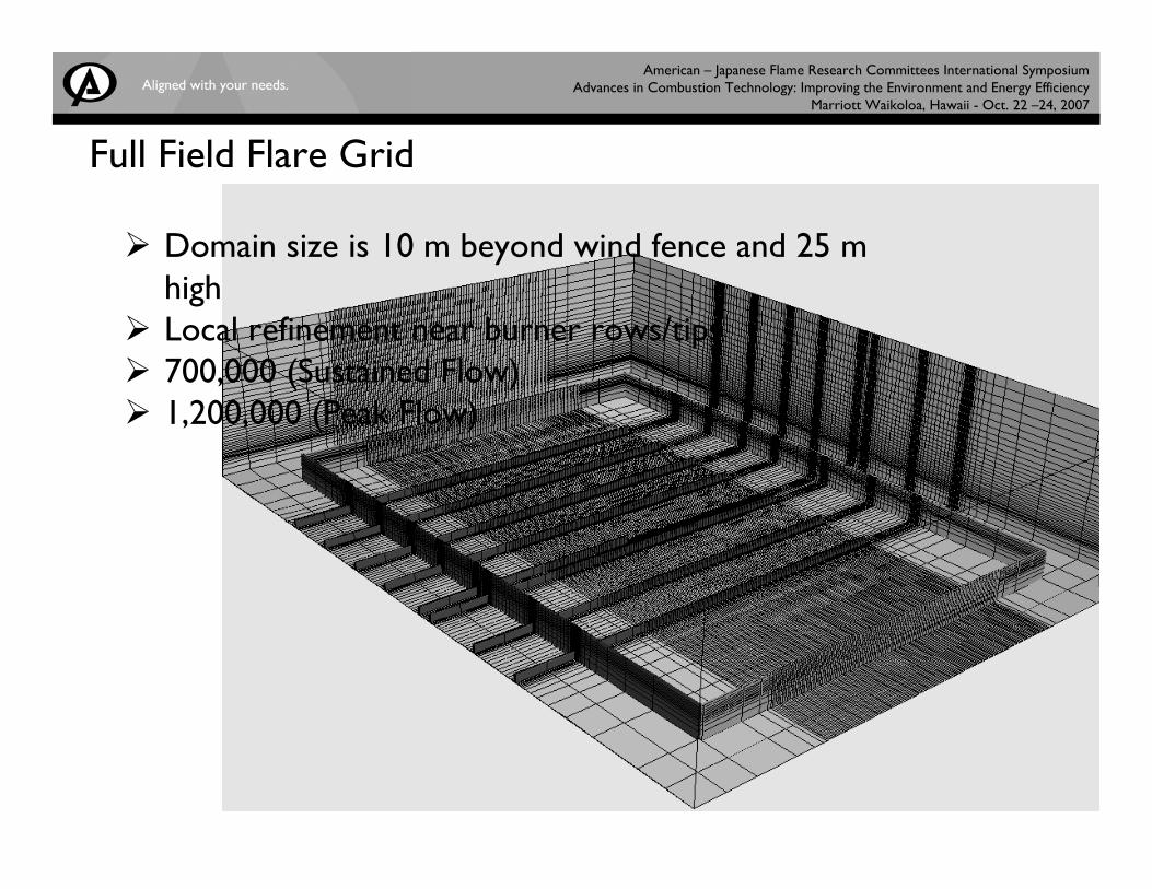
Full Field Flare Grid
Domain size is 10 m beyond wind fence and 25 m highLocal refinement near burner rows/tips700,000 (Sustained Flow)1,200,000 (Peak Flow)
American – Japanese Flame Research Committees International Symposium Advances in Combustion Technology: Improving the Environment and Energy Efficiency
Marriott Waikoloa, Hawaii - Oct. 22 –24, 2007
Slide 35
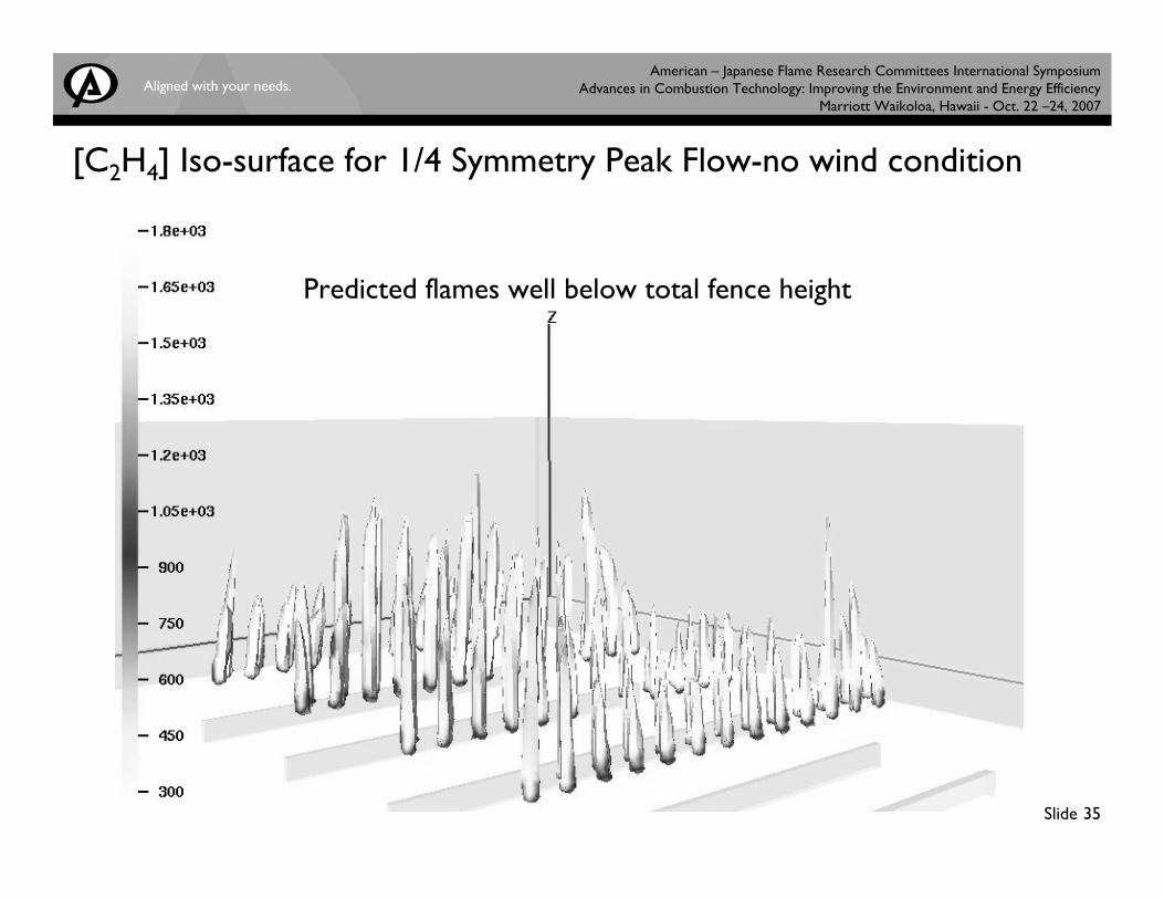
[C2H4] Iso-surface for 1/4 Symmetry Peak Flow-no wind condition
Predicted flames well below total fence height
American – Japanese Flame Research Committees International Symposium Advances in Combustion Technology: Improving the Environment and Energy Efficiency
Marriott Waikoloa, Hawaii - Oct. 22 –24, 2007
Slide 36
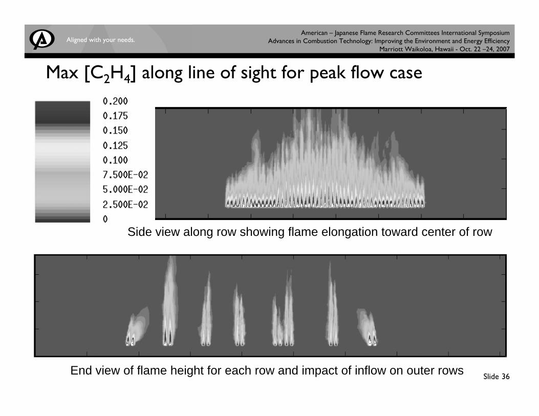
Max [C2H4] along line of sight for peak flow case
Side view along row showing flame elongation toward center of row
End view of flame height for each row and impact of inflow on outer rows
American – Japanese Flame Research Committees International Symposium Advances in Combustion Technology: Improving the Environment and Energy Efficiency
Marriott Waikoloa, Hawaii - Oct. 22 –24, 2007
Slide 37
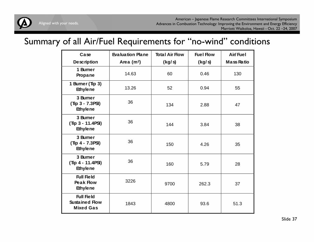
Summary of all Air/Fuel Requirements for “no-wind” conditionsCase
Description Evaluation Plane
Area (m2) Total Air Flow
(kg/s) Fuel Flow
(kg/s) Air/Fuel
Mass Ratio 1 Burner Propane 14.63 60 0.46 130
1 Burner (Tip 3) Ethylene 13.26 52 0.94 55
3 Burner (Tip 3 - 7.3PSI)
Ethylene 36 134 2.88 47
3 Burner (Tip 3 - 11.4PSI)
Ethylene 36 144 3.84 38
3 Burner (Tip 4 - 7.3PSI)
Ethylene 36 150 4.26 35
3 Burner (Tip 4 - 11.4PSI)
Ethylene 36 160 5.79 28
Full Field Peak Flow Ethylene
3226 9700 262.3 37
Full Field Sustained Flow
Mixed Gas 1843 4800 93.6 51.3
American – Japanese Flame Research Committees International Symposium Advances in Combustion Technology: Improving the Environment and Energy Efficiency
Marriott Waikoloa, Hawaii - Oct. 22 –24, 2007
Slide 38
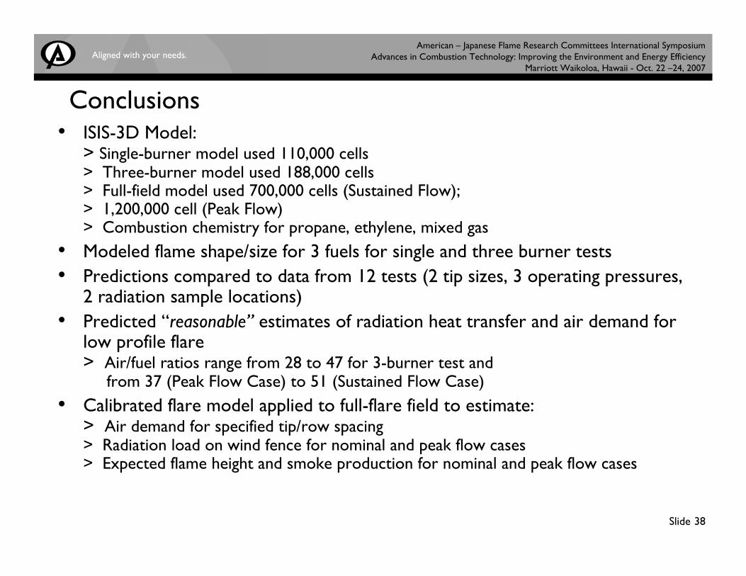
Conclusions• ISIS-3D Model:
> Single-burner model used 110,000 cells> Three-burner model used 188,000 cells> Full-field model used 700,000 cells (Sustained Flow); > 1,200,000 cell (Peak Flow)> Combustion chemistry for propane, ethylene, mixed gas
• Modeled flame shape/size for 3 fuels for single and three burner tests• Predictions compared to data from 12 tests (2 tip sizes, 3 operating pressures,
2 radiation sample locations)• Predicted “reasonable” estimates of radiation heat transfer and air demand for
low profile flare> Air/fuel ratios range from 28 to 47 for 3-burner test and
from 37 (Peak Flow Case) to 51 (Sustained Flow Case)• Calibrated flare model applied to full-flare field to estimate:
> Air demand for specified tip/row spacing> Radiation load on wind fence for nominal and peak flow cases> Expected flame height and smoke production for nominal and peak flow cases