Embed Size (px)
Citation preview
9
Estimation of Stator Winding Temperature of a Three-Phase Induction Motor
Afrah Thamer Abdullah1, Amer Mejbel Ali2 Electrical Engineering Department, Faculty of Engineering, Mustansiriayah University, Baghdad
[email protected], [email protected]
Abstract— This paper adopted a thermal network method (TNM) based on Motor-CAD with MATLAB/Simulink software, and finite element method (FEM) based on Motor-CAD with Flux2D software, to estimate the stator winding temperature of a totally enclosed fan-cooled (TEFC), squirrel cage, three-phase induction motor. The three software packages were adopted successfully with a good agreement among their results resulting in preferring using Motor-CAD in obtaining results, and using Flux2D with MATLAB to validate these results. The success of triple-software methodology will give the induction motor designer a well-validated tool in attaining a safe motor operation without exceeding the maximum allowable stator winding temperature rise, and without using an experimental test based on an expensive manufacturing motor.
Index Terms—Three-phase induction motor, Thermal analysis, Finite element method, Thermal network method, Motor-CAD
I. INTRODUCTION
The electrical machine is a complicated system consisting of diverse materials with various thermal properties. The most common AC motor used in the industry implementations is a three-phase induction motor that converts electrical energy into mechanical energy. The converting energy from one form to another produces losses; these losses are responsible for generating heat inside the motor. Temperature rise is an essential factor that affects the performance of the electrical machines. The temperature rise in the stator windings to a high value leads to a reduction in the lifetime of the windings insulation, and it reduces the operational life of the machine [1][2]. Other problems of overheating come from the changes in the motor geometry caused by thermal extension of the machine components and mechanical stresses. Although there are many research works concerned with studying the thermal analyses of a three-phase induction motor, but few of them considered the thermal analysis of stator winding only. Zhi Gao (2006) has developed an efficient and reliable stator winding temperature estimation system for small and medium-size induction machines, by developing a sensorless temperature for a monitoring system to provide an accurate temperature estimation, that is able to respond to changes in machine cooling capacity [3]. Idoughi et al. (2011) proposed a method for parameters calculation of a stator winding thermal model, with a complex slot geometry. This method is based on the division of the geometry using a finite integration technicality [4]. Gedzurs (2018) proposed a method for the estimation of stator winding temperature for S1 duty cycle induction motors. This method depends on the variation of rotor speed with rotor resistance, with performing experimental tests on a three-phase induction motor under good and bad cooling conditions [5]. This work aims to estimate the stator winding temperature with load changing, for a TEFC, squirrel cage, three-phase, induction motor, using TNM
DOI: https://doi.org/10.33103/uot.ijccce.19.2.2

10
and FEM methods, based on a combination of Motor-CAD, Flux2D, and MATLAB/Simulink software.
II. METHODS OF THERMAL ANALYSIS
A. Thermal network method
The thermal network method (TNM) is one of the most important methods used in electrical machines thermal analysis because it gives more details about the calculating temperature, and how heat is distributed and transferred. Motor-CAD thermal model relies upon TNM. The principle consists in the way that machine is divided into basic thermal elements representing a combination of conduction, convection, and radiation heat transfer operations. The structure of a TEFC induction motor model can be planned within the fashion of an electric network [6]. This network for the test motor is shown in Figure1, and it consists of the following parts: 1. Thermal nodes:- are zones of constant temperature. The potential of a node appears the absolute temperature of that node. 2. Loss sources:- are comparable to a current source in an electric circuit. In the TEFC induction motor model, iron losses, copper losses, and stray load losses are interested. 3. Thermal resistors:- are substances of heat conduction. In a TEFC induction motor, only heat conduction and convection are interested, while the effect of heat radiation is ignored [7]. 4. Thermal conductors:- the model clarifies the heat conduction or convection by the heat conductance rather than the reverse of heat resistance. 5. Thermal capacitors:- clarify the capability to store heat energy in a certain zone. In the steady state analysis, the thermal circuit of a three-phase induction motor comprises of thermal resistances and thermal sources linked between the motor component nodes. While the transient analysis, thermal capacities are used to observe changes in the internal energy of the body over time. This method is very fast, simple mathematical form, easy to implement, and more suitable with the degree of temperature gradients in small machines.
FIG.1.TNM OF THE TEST MOTOR BY MOTOR-CAD

11
B. Thermal analysis by finite element method
The finite element method (FEM) is a numerical method utilized to solve problems of engineering like electromagnetic, mass transport, heat transfer, and fluid flow. The method produces the approximate values of the unknown at the number of nodes separated above the range [8]. To solve the problem, it divides the big problem into smaller and simpler parts which are called finite elements. Simple equations that compose these limited elements are then compiled into a larger system of equations that constitutes the whole problem. Motor-CAD has a finite element solution for the stator winding only. The thermal study of the test motor by FEM is achieved by using Flux2D software to find the temperature distribution at any point of the induction motor. This method is particularly appropriate with large temperature gradients [9], but the defect is that it takes more time to process with respect to TNM. The finite element method model for the test motor by Flux2D is shown in Figure 2.
FIG. 2. FEM MODEL FOR TEST MOTOR BY FLUX2D
III. MATHEMATICAL BACKGROUND
The heat transfer mathematical basics for the thermal analysis of a three-phase induction motor can be described as follows [10]:
A. Heat transfer by conduction
The heat is transferred by conduction in a solid material such as the stator and rotor. The general equation for heat conduction is given as in equation1.
c = (λx ) + (λy ) + (λz +Q (1)
Where ρc is the density, is the thermal conductivity, T is the temperature, and Q is the dissipated power density. In many cases, only one-dimensional heat flux needs to be considered. Fourier's law is used to connect the heat flux and the temperature gradient. The heat flux q is given as:
q = - λ ∂T/∂x (2)

12
B. Heat transfer by convection
In convection, the heat is moved from one place to another by the locomotion of fluids. The TEFC motor is supported by an external fan, where the air is pushed on the frame of the motor. The expression for the heat flux is set as:
q = α (Tw - T∞ ) (3)
Where α is the heat transfer coefficient and Tw and T∞ are the temperatures of the surface and the ambient cooling medium, respectively.
C. Heat sources (power losses)
The motor power losses are divided into five types: Iron losses , PFe. Stator copper losses , Pcu1. Rotor copper losses , Pcu2. Friction and windage losses . Stray load losses.
These losses must be calculated, then input as heat sources for the thermal motor analysis.
IV. STATOR WINDING TEMPERATURE RISE
Stator winding resistance is the main factor in generating heat in the machine. All metal conductors have a temperature coefficient of resistance (α). The resistivity of a metal is a function of the temperature (T) and is calculated as in equation 4 [11]:
ρ (T) = ρ (To) [1+α (T-To)] (4)
Where Tois the reference temperature and O is the resistivity at temperature To .The stator winding temperature rise is defined as the difference between the ambient temperature and the temperature of the stator winding when the motor is running at full load. The temperature rise is measured in the stator windings because it is the hottest part (or hotspot) of the motor. The operating temperature of the stator windings mainly affects the life of the insulators. The maximum permissible machine temperature for each class of insulation is always based on the ambient temperature of 40 o C. The allowable temperature rise in the stator winding of class F insulation with 1.0 service factor is shown in Table 1 [12].
TABLE 1. STATOR WINDING TEMPERATURE CHARACTERISTIC FOR INSULATION CLASS F
V. MODELING OF THE TEST MOTOR BY MOTOR-CAD
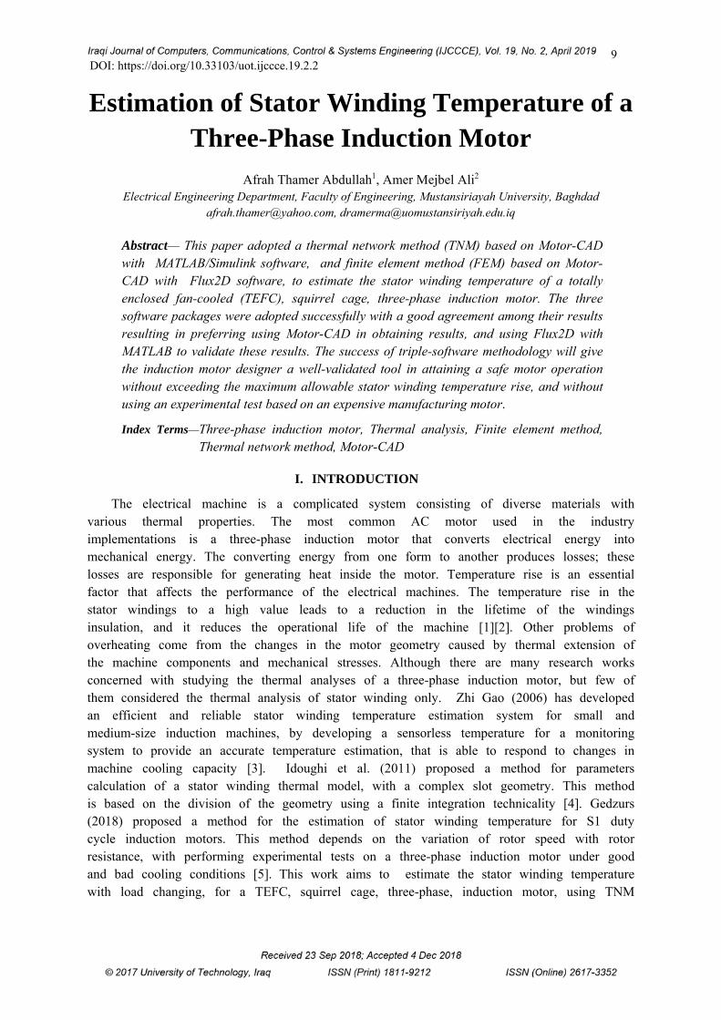
A 2.2 kW, 2 poles, TEFC, class F, S1 duty cycle,1 service factor, 3-phase, squirrel-cage induction motor is modeled by using Motor-CAD to study the thermal manner of the machine, and to show how the heat is distributed in the stator windings. The geometry for the test motor is shown in Figure 3. The winding pattern for the (slot/pole) combination of this machine is set up automatically in Motor-CAD software. In the test motor, we have a single layer winding with 184 turns per coil. Figure 4 shows the test motor stator slot model achieved by Motor-CAD.
Maximum allowable temperature rise of stator winding 105 oC
Ambient temperature 40 oC
Allowance for hot spots 10 oC
Maximum allowable temperature of stator winding 155 oC

13
FIG. 3. RADIAL CROSS SECTION FOR THE TEST MOTOR BY MOTOR-CAD
FIG .4. STATOR SLOT MODEL BY MOTOR-CAD
The materials used in the modeling of the test motor are shown in Figure 5. The losses have been calculated separately at different loading conditions and entered in Motor-CAD as in Figure 6. The thermal model can be set up with housing type, materials, and cooling options, etc. Finally, the model can be solved by clicking on solve thermal model button to calculate the machine temperatures.
14
FIG.5. MATERIALS SELECTED FOR THE TEST MOTOR BY MOTOR- CAD
FIG.6. LOSSES INSERTION FOR THE TEST MOTOR
VI. THERMAL ANALYSIS BY MATLAB/SIMULINK
The test motor was simulated by MATLAB/SIMULINK based on a lumped thermal model. Heat generated due to power losses in the stator iron back, stator winding, and the rotor winding is represented by three heat flow sources: stator iron losses, stator copper losses, and rotor copper losses.
15
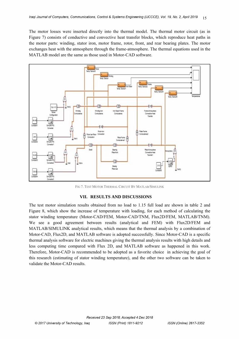
The motor losses were inserted directly into the thermal model. The thermal motor circuit (as in Figure 7) consists of conductive and convective heat transfer blocks, which reproduce heat paths in the motor parts: winding, stator iron, motor frame, rotor, front, and rear bearing plates. The motor exchanges heat with the atmosphere through the frame-atmosphere. The thermal equations used in the MATLAB model are the same as those used in Motor-CAD software.
FIG 7. TEST MOTOR THERMAL CIRCUIT BY MATLAB/SIMULINK
VII. RESULTS AND DISCUSSIONS
The test motor simulation results obtained from no load to 1.15 full load are shown in table 2 and Figure 8, which show the increase of temperature with loading, for each method of calculating the stator winding temperature (Motor-CAD/FEM, Motor-CAD/TNM, Flux2D/FEM, MATLAB/TNM). We see a good agreement between results (analytical and FEM) with Flux2D/FEM and MATLAB/SIMULINK analytical results, which means that the thermal analysis by a combination of Motor-CAD, Flux2D, and MATLAB software is adopted successfully. Since Motor-CAD is a specific thermal analysis software for electric machines giving the thermal analysis results with high details and less computing time compared with Flux 2D, and MATLAB software as happened in this work. Therefore, Motor-CAD is recommended to be adopted as a favorite choice in achieving the goal of this research (estimating of stator winding temperature), and the other two software can be taken to validate the Motor-CAD results.

16
TABLE 2. THE PREDICTED TEMPERATURE OF STATOR WINDING WITH LOAD VARYING
Stator winding temperature (o C) Motor Load (W)
MATLAB
Flux2D Motor-CAD
(TNM) (FEM) (TNM) (FEM)
44.5 47.05 50.60 50.24 No-load 47.31 48.08 51.78 51.31 220 (0.1FL) 51.9 50.22 53.71 53.04 440 (0.2 FL) 54.4 52.95 56.25 55.33 660 (0.3 FL) 57.1 55.5 59.06 57.91 880 (0.4 FL) 60.05 58.8 62.53 61.07 1100(0.5FL) 63.6 64.8 68.09 66.1 1320(0.6FL) 71.3 73.2 75.72 73 1540(0.7FL) 80.5 81.25 83.70 80.27 1760(0.8FL) 87.51 88.4 91.32 87.27 1980(0.9FL)
97 104.6 104.15 99.4 2200 (FL) 103.3 108.6 108.9 103.3 2310(1.0FL) 113.6 114.5 116.2 110.3 2420(1.1FL) 121.1 120. 6 123.36 118.6 2530(1.15FL)
FIG. 8. VARIATION OF STATOR WINDING TEMPERATURE WITH LOAD
VIII. CONCLUSION
In this paper, a stator winding temperature of a TEFC, squirrel cage, three-phase induction motor was estimated successfully with increases in motor loading. The proposed methodology was done based on a thermal network method (Motor-CAD and MATLAB), and finite element method (Motor-CAD and Flux2D). The four results obtained for stator winding temperature at each loading conditions show a good agreement and guide the users to adopt Motor-CAD as main software, and Flux2D with MATLAB as validation software. The multi-software methodology adopted in this work will give the motor designer a good tool to evaluate the stator winding temperature at different loading conditions without the need to achieve a costly test based on a well-manufactured prototype motor.
17
REFERENCES
[1] Gnacinski, P., "Windings temperature and loss of life of an induction machine under voltage unbalance combined with over-or under voltages," IEEE Trans. on Energy Conversion, Vol. 23, No. 2, June 2008.
[2] Fouladgar, J. and E. Chauveau, "The influence of the harmonics on the temperature of electrical machines," IEEE Trans. on Magnetics, Vol. 41, No. 5, May 2005.
[3] Zhi Gao, "Sensorless stator winding temperature estimation for induction machines”, PhD dissertation ,Georgia institution of technology,2006.
[4] L. Idoughi, X. Miniger, L. Bernard, F. Bouillarrlt, "Determination of thermal model parameters for stator slot using numerical methods", Progress In Electromagnetics Research Symposium Proceedings, Marrakesh, Morocco, Mar. 20-23, 2011.
[5] Aleksejs Gedzurs, "Indirect induction motor stator winding temperature estimation”, Engineering for rural development, Jelgava, 23, pp. 681-686, 2018.
[6] A. Boglietti, A. Cavagnino, and D. A. Staton, "TEFC Induction Motors Thermal models :A parameter sensitivity analysis," IEEE Trans. Ind. Appl., vol. 41, no. 3, pp. 756–763, May/Jun. 2005.
[7] A. Boglietti, A. Cavagnino, M. Parvis, and A. Vallan, "Evaluation of radiation thermal resistances in industrial motors," IEEE Trans. Ind. Appl., vol. 42, no. 3, pp. 688–693, May/Jun. 2006.
[8] Flux2D software, www.cedrat.com. [9] J P Holman, Heat Transfer, McGraw-Hill Book Company, 1986. [10] Gunnar Kylander, "Thermal modeling of small cage induction motors”, PhD dissertation, Chambers University of
Technology, 1995. [11] M.R. Ward , "Electrical Engineering Science", McGraw-Hill Book Company ,1971. [12] "NEMA Standard Publication MG-1: Motors and Generators" , National Electrical Manufactures Association
,USA , 2009.


![Untitled-1 [] · Run Capacitor Stator Winding Relay Rotary Switch Rotor Start capacitor Main or Run Windin Stator Winding Main Winding Start capacitor Rotor](https://img.pdfslide.us/doc/110x75/5fc791720420d159865384b0/untitled-1-run-capacitor-stator-winding-relay-rotary-switch-rotor-start-capacitor.jpg)


![Stator Laminated stator · · 2016-11-16Winding hotspot Average winding Lowest winding Magnet Stator back iron Housing 0 1800 3600 5400 7200 9000 20 40 60 80 100 120 140 Time [secs]]](https://img.pdfslide.us/doc/110x75/5b04e5c37f8b9a6c0b8e6eee/stator-laminated-stator-hotspot-average-winding-lowest-winding-magnet-stator-back.jpg)