Embed Size (px)
Citation preview
Grid-Connected Dual Stator-Winding Induction Generator … 1
http://dx.doi.org/10.6113/JPE.2014.14.1.???
ISSN(Print): 1598-2092 / ISSN(Online): 2093-4718
JPE ??-?-?
Grid-Connected Dual Stator-Winding Induction
Generator Wind Power System over a Wide Wind
Speed Range
Kai Shi†,*, Peifeng Xu*, Zengqiang Wan*, Zhiming Fang*, Rongke Liu** and Dean Zhao*
†*School of Electrical and Information Engineering, Jiangsu University, Zhenjiang, China
**KTK Group, Changzhou, China
Abstract
This paper presents a grid-connected dual stator- winding induction generator (DWIG) wind power system suitable for
wide-ranged wind speed. The parallel connection via a unidirectional diode between dc buses of both stator-winding sides is
employed in this DWIG system, which can output a high dc voltage over a wide wind speed range. The grid-connected inverter
(GCI) does not need a booster converter, which increases the efficiency of wind energy utilization and simplifies the hardware
topology and control strategy of the grid- connected inverter. In view of particularities of parallel topology and the adopted
generator control strategy, a novel excitation-capacitor optimization solution is proposed to reduce the volume and weight of the
static excitation controller (SEC). Furthermore, when this excitation- capacitor optimization is carried out, the maximum power
tracking problem is also considered. All the problems are resolved by a combination control for DWIG and GCI. Experimental
results on the platform of 37-kW/600-V prototype show that the proposed DWIG wind power system can output a constant dc
voltage over a wide rotor speed range for a grid-connected operation and that the proposed excitation optimization scheme is
effective.
Key words: Dual stator- winding induction generator (DWIG), Excitation-capacitor optimization, Grid-connected, Wind power,
Wide wind speed
I. INTRODUCTION
Since the beginning of the 21st century, wind energy has
become one of the most important ways to resolve the
problem of energy crisis. Wind energy has the advantages of
vast quantity, wide regional distribution, and non- pollution.
As the most commonly used wind turbine, both the
direct-drive permanent magnet synchronous generator
(PMSG) and doubly-fed induction generator (DFIG) wind
turbines have inherent disadvantages [1]. The PMSG wind
turbine is very expensive for its rare permanent magnetic
material, and the direct-drive structure is large-sized and
heavy. The DFIG requires brushes and copper rings for
power transfer from/to the rotor windings, which leads to
higher maintenance costs [2].
As a novel induction generator proposed at the beginning
of this century, DWIG not only inherits some advantages of
conventional induction generators (IGs) such as robust
brushless construction, lower maintenance cost, and favor-
able overload protection [3], [4], but also overcomes its
inherent drawbacks of poor voltage regulation with load and
rotor speed variation [5], [6]. The lack of electrical
connection between the two sets of stator windings makes it
exhibit a high-quality control performance under variations of
speed and load. A pulse width modulation (PWM) controlled
SEC connected to the control winding is employed to provide
variable compensating reactive power to effectively regulate
the magnitude of output voltage and load frequency [7]. At
the same time, harmonics induced by the applied power
converter connected in series or parallel with the load in a
conventional IG system can be minimized and even
eliminated [6], [7]. In the last years, researches on DWIG for
standalone power systems applications were carried out, and
excellent static and dynamic performances for DWIG has
been demonstrated [7], [8]. With the increasing need of
Manuscript received Sep. 15, 2015; accepted Feb. 14, 2016 Recommended for publication by Associate Editor Jun-Keun Ji.
†Corresponding Author: [email protected]
Tel: +86-0511-88791245, Jiangsu University * School of Electrical and Information Engineering, Jiangsu University,
Zhenjiang, China ** KTK Group, Changzhou, China
2 Journal of Power Electronics, Vol. ?, No. ?, Month Year
offshore wind farms [9], [10], DWIG power generation
systems were proposed for offshore wind farms suitable for
high-voltage dc (HVDC) transmission [11], [12].
Being suitable for operating under medium-low speed
regions realized by the optimal design of DWIG structure
allows for the removal of the high-speed gearbox, which is
expensive and difficult to maintain, employed in the DFIG
wind turbine. The favorable capability of operating in the
flux-weakening region broadens the operational speed range
of DWIG. Since the ac capacitor bank on the power winding
provides the reactive power as well as reduces the inductance
of the rectifier load, the bank can be optimized to keep the
control-winding current at a minimum level to decrease the
capacity of SEC [8], [10], [13]. Thus the DWIG wind power
system has been verified to be a strong competitor comparing
to other conventional wind turbines.
However, wind energy has its own unique characteristic
that it varies with the time of the day, month, or season.
Much of the annual gross electricity production of wind
turbines depends on the available wind speed range. For this
reason, the research attention of wind energy is focused to
improve wind energy extraction and extend the operating
wind speed range of wind turbines, especially in barren areas.
For the limitation of the cost of entire wind turbine system
and the capacity of excitation converter, the direct- drive
PMSG and DFIG are not cost-effective for extending the
operating range of wind speed. For the direct-drive PMSG
wind turbine, the more expensive high-gain boost converter is
necessary for the higher dc voltage under low wind speed for
stable grid-connected operations. As wind speed falls, DFIG
reverts to a conventional IG operation mode, with the total
electric power flowing from the rotor-side converter to the
grid. Hence, the capacity of the rotor-side excitation
converter restricts the actual adaptive operation wind speed
range of DFIG. Furthermore, particular control strategy for
respective wind turbine and reformed maximum power
tracking strategy are also proposed to expand the operating
range of the wind turbine and increase the output power,
especially in areas with low wind speed [14], [15].
To resolve this problem, the topology of DWIG wind
power systems is improved to enhance its unsatisfactory
capability of wind energy utilization in low wind speed
regions [16]. In order to make full use of wind energy, both
sides of a dc bus are connected in parallel using a diode. The
control-winding-flux-orientation control strategy for DWIG
and efficiency optimization scheme in the low-speed range
were studied in [16], where different control strategies for
low and high wind speeds ensure a stable high dc output
voltage over a wider wind speed range. Nonetheless, neither
were the topology of GCI or grid-connected operation control
strategy involved in the work, nor was the optimization of
excitation capacitor in the parallel topology for
grid-connected operation studied in [16]. Since the particular
topology of parallel connection between two dc bus sides
results in an entirely different active and reactive current
component in low and high wind speed regions, the excitation
optimization scheme should be designed and reconfirmed for
an improved system topology and grid-connection operation.
Furthermore, the maximum power tracking problem should
be considered when excitation capacitances are optimized.
In this paper, a grid-connected DWIG system for wind
energy generation applications is explored. The topology of
parallel connection with both dc bus sides is still employed to
output a stable high dc voltage in a wide wind speed range.
Because of this advantage in parallel topology, the booster
converter is removed in the hardware structure of GCI for
grid-connected operation, which is an outstanding advantage
of the proposed grid-connected DWIG wind turbine. The
different compositions of active and reactive current in low
and high wind speed ranges are fully considered when the
capacity of the SEC is optimized while the maximum power
tracking requirement is satisfied. Meanwhile, an appropriate
control strategy for GCI without a booster converter is
presented. Based on a grid-connected DWIG wind turbine
prototype, the above work is verified by experimental results.
The rest of this paper is organized as follows. In Section II,
a system structure diagram of the proposed grid- connected
DWIG wind power system is introduced, and the operational
principle is also discussed in detail. Then, the respective and
integrated control strategies for the proposed
wide-speed-range-operation grid-connected DWIG wind
power system are presented in Section III. In Section IV, the
optimization scheme for the excitation capacitors and the
simulation verification are shown. Finally, experimental
results are discussed in Section V, and Section VI concludes
this work.
II. GRID-CONNECTED DWIG WIND POWER
SYSTEM AND OPERATIONAL PRINCIPLE
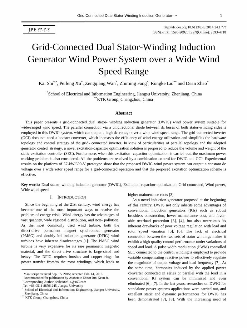
The structure diagram of the proposed grid-connected
DWIG wind power system is shown in Fig. 1. The first- order
step-up gearbox is built to deliver mechanical energy from
the wind machine to generator. The DWIG consists of a
standard squirrel-cage brushless rotor and a stator with two
separate three-phase star windings wound by 30º electrical
angle shifted. The power winding is linked with ac excitation
capacitors and a rectifier bridge. A filter induction between
the control winding and SEC is adopted to minimize
SEC-induced harmonics. The dc bus of SEC is connected to
the dc filter capacitor. The storage battery isolated from the
high dc voltage through a diode, which contributes to the
excitation at the beginning of voltage build-up. Both dc buses
on the control side and power side are connected parallel via
a diode. The positive dc-bus terminal of SEC is connected to
the positive one of the rectifier bridge, while their negative
Grid-Connected Dual Stator-Winding Induction Generator … 3
terminals are connected directly. The diode provides a
transmission channel for electrical power under low wind
speed. The switch status of this diode is determined by the
voltage difference between both sides of the dc bus. The dc
bus of GCI is linked to the output dc bus of DWIG directly
without a booster device, which increases the efficiency of
wind energy utilization and simplifies the hardware structure
and control of the grid-connected operation.
Under low wind speed, the output dc-bus voltage of the
rectifier bridge is too low to reach the given value even if the
entire capacity of SEC supplies the reactive excitation power.
The voltage-boosting ability of SEC is exploited to acquire a
high dc voltage here. Thus, the electrical power is supplied to
the load through the dc bus of SEC when the diode is on,
while the rectifier bridge on the power side is blocked.
The output voltage of the rectifier bridge increases with the
rotor speed of DWIG, and also rises with the wind speed.
Under a high wind speed, the diode will turn off once the
output voltage of the rectifier bridge exceeds the dc-bus
voltage of SEC. The electrical power is transferred from the
rectifier bridge to the load, and reactive power is provided by
SEC and ac excitation capacitors at that moment. Thus, a
stable output dc voltage is achieved by adjusting the reactive
power from SEC under such working conditions. The volume
and capacity of SEC can be optimized by choosing a
reasonable excitation capacitance. Meanwhile, the dc-bus
voltage of SEC is also obliged to be constant for the steady
operation of SEC.
The active power from generator is transferred from the
GCI to grid, and the power factor usually equals 1. If a
compensation reactive power is required, the power factor
can also be a different value. The maximum power tracking is
accomplished by common control schemes of generator and
inverter. Therefore, it can be found that the combined system
control strategy and corresponding specific excitation
capacitor optimization are both important in this grid-
connected wind power system.
It should be noted that the two sets of stator windings have
the same rated dc-bus output voltage. In order to achieve a
better dynamic performance after two sides of the dc bus are
connected in parallel, the number of control- winding turns
should be fewer than the number of power- winding turns in
order to decrease the voltage drop on the impedance of filter
inductance. In other words, the terminal voltage of the control
winding should be lower than that of the power winding.
III. CONTROL STRATEGY FOR GRID-CONNECTED
DWIG WIND TURBINE FOR WIDE SPEED
RANGE
The emphasis to stable operation of the proposed grid-
connected DWIG wind turbine is to output a constant high dc
voltage in a wide speed range, which helps avoid the
requirement of a booster converter for the grid-connected
inverter. Another emphasis to stable operation is to realize
grid-connected operation by the integrated control of
generator and inverter while tracking the maximum power.
Thus, the dc voltage control strategy where the active and
reactive current of SEC are adjusted and the cooperation
control between generator and inverter are both important
elements in this system. These elements are included in the
following control strategies for the grid-connected DWIG
wind turbine.
A. Principle of Control-winding-voltage-orientation
Control Strategy and Instantaneous Power Theory
Based on the instantaneous reactive power theory [17],
[18], the instantaneous active power p
and reactive power
q
are defined in (1) using the power-invariance Park
transformation and arbitrary reference coordinates,
x x y y
x y y x
p u i u i
q u i u i
(1)
where u and i are the instantaneous voltage and current,
respectively, for a three-phase circuit, and sub- scripts x and y
represent the direct and quadrature axes for arbitrary
reference coordinates. For example, subscripts d and q will be
used in two-phase rotating reference coordinates. Similarly,
for the stationary coordinate, the subscripts α and β will be
used. Thus, it can be found that, in (1), the values of p
and
q
are independent of the defined reference coordinates.
From (1), if the instantaneous power and voltage are
known, the corresponding current can be calculated as
follows,
2 2
2 2
x y
x
x y
y x
y
x y
pu qui
u u
pu qui
u u
(2)
Replacing subscripts x and y in (2) with d and q,
respectively, the corresponding current components for d-q
rotating reference coordinates are
DWIG
Gear box
Wind
Turbine
Rectifier
Excitation Capacitor
SEC
Battery
Power Winding
Control
Winding
Filter Inductance
Diode
Cs
C
Grid-connected
Inverter
GridFilter
Fig. 1. Structural diagram of the proposed grid-connected
DWIG wind power system.
4 Journal of Power Electronics, Vol. ?, No. ?, Month Year
22 2
22 2
d q d q
d
d q
q d q d
q
d q
pu qu pu qui
u u
pu qu pu qui
u u
U
U
(3)
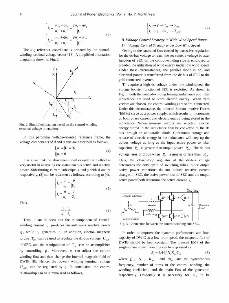
The d-q reference coordinate is oriented by the control-
winding terminal voltage vector [16]. A simplified orientation
diagram is shown in Fig. 2.
In this particular voltage-oriented reference frame, the
voltage components of d and q axis are described as follows,
0
d s
q
u
u
U U (4)
It is clear that the abovementioned orientation method is
very useful in analyzing the instantaneous active and reactive
power. Substituting current subscripts x and y with d and q,
respectively, (2) can be rewritten as follows, according to (4),
d
d s
q
d s
p pi
u
q qi
u
U
U
(5)
Thus,
d
q
p i
q i (6)
Thus it can be seen that the q component of control-
winding current qi produces instantaneous reactive power
q , while di generates p . In addition, electro- magnetic
torque emT
can be used to regulate the dc-bus voltage sDCU
of SEC, and the manipulation of emT
can be accomplished
by controlling p . Moreover, q
can adjust the control
winding flux and then change the internal magnetic field of
DWIG [8]. Hence, the power- winding terminal voltage
pDCU can be regulated by q. In conclusion, the control
relationship can be summarized as follows,
d em sDC
q m pDC
i p T U
i q U
(7)
B. Voltage Control Strategy in Wide Wind Speed Range
1) Voltage Control Strategy under Low Wind Speed
Owing to the saturated flux caused by excessive regulation
for the dc-bus voltage to reach the set value, a voltage booster
function of SEC on the control-winding side is employed to
broaden the utilization of wind energy under low wind speed.
Under these circumstances, the parallel diode is on, and
electrical power is transferred from the dc bus of SEC to the
grid-connected inverter.
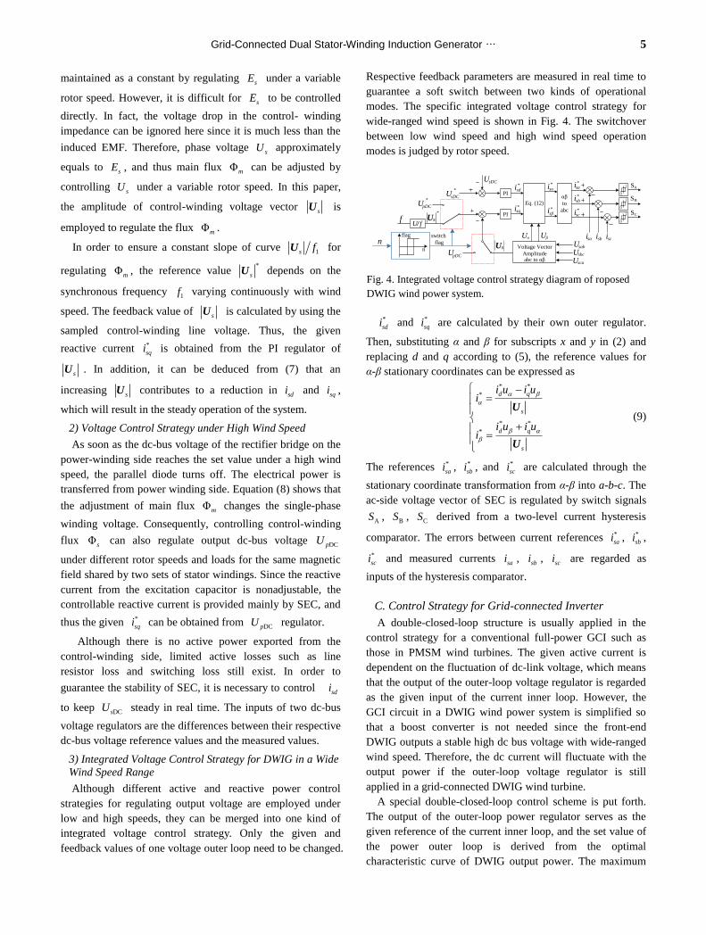
To acquire a high dc voltage under low wind speed, the
voltage booster function of SEC is exploited. As shown in
Fig. 3, both the control-winding leakage inductance and filter
inductance are used to store electric energy. When zero
vectors are chosen, the control windings are short- connected.
Under this circumstance, the induced Electro- motive Forces
(EMFs) serve as a power supply, which results in increments
of both phase current and electric energy being stored in the
inductance. When nonzero vectors are selected, electric
energy stored in the inductance will be conveyed to the dc
bus through an antiparallel diode. Continuous storage and
release of electric energy in the inductance will step up the
dc-bus voltage as long as the input active power to filter
capacitor inP is greater than output power
outP . The dc-bus
voltage rises or drops when inP is greater or less than
outP .
Thus, the closed-loop regulator of the dc-bus voltage
determines the duty cycle of switching tubes. Since output
active power variations do not induce reactive current
changes in SEC, the active power loss of SEC and the output
active power both determine the active current sdi .
In order to improve the dynamic performance and load
capacity of DWIG at a low rotor speed, the magnetic flux of
DWIG should be kept constant. The induced EMF of the
single-phase control winding can be expressed as
14.44 Φs s ws mE f N K (8)
where1f ,
sN , wsK , and Φm
are the synchronous
frequency, number of turns in the control winding, the
winding coefficient, and the main flux of the generator,
respectively. Obviously it is necessary for Φm to be
d
q
Us
Is
I
I
U
U
I
I
q
d
Id
Fig. 2. Simplified diagram based on the control-winding
terminal voltage orientation.
+C
L
sL
sLsL
1T
2T 4T
3T
6T
5T1D
2D
3D 5D
4D 6D
Equivalent
control winding
Filter
inductance
Leakage inductance
load
Pin Pout
Fig. 3. Connection between the control winding and SEC.
Grid-Connected Dual Stator-Winding Induction Generator … 5
maintained as a constant by regulating sE under a variable
rotor speed. However, it is difficult for sE
to be controlled
directly. In fact, the voltage drop in the control- winding
impedance can be ignored here since it is much less than the
induced EMF. Therefore, phase voltage sU
approximately
equals to sE , and thus main flux Φm
can be adjusted by
controlling sU under a variable rotor speed. In this paper,
the amplitude of control-winding voltage vector sU
is
employed to regulate the flux Φm.
In order to ensure a constant slope of curve 1s fU
for
regulating Φm, the reference value
*
sU
depends on the
synchronous frequency 1f varying continuously with wind
speed. The feedback value of sU
is calculated by using the
sampled control-winding line voltage. Thus, the given
reactive current *
sqi is obtained from the PI regulator of
sU . In addition, it can be deduced from (7) that an
increasing sU
contributes to a reduction in
sdi
and sqi ,
which will result in the steady operation of the system.
2) Voltage Control Strategy under High Wind Speed
As soon as the dc-bus voltage of the rectifier bridge on the
power-winding side reaches the set value under a high wind
speed, the parallel diode turns off. The electrical power is
transferred from power winding side. Equation (8) shows that
the adjustment of main flux Φm changes the single-phase
winding voltage. Consequently, controlling control-winding
flux Φs can also regulate output dc-bus voltage DCpU
under different rotor speeds and loads for the same magnetic
field shared by two sets of stator windings. Since the reactive
current from the excitation capacitor is nonadjustable, the
controllable reactive current is provided mainly by SEC, and
thus the given *
sqi
can be obtained from DCpU
regulator.
Although there is no active power exported from the
control-winding side, limited active losses such as line
resistor loss and switching loss still exist. In order to
guarantee the stability of SEC, it is necessary to control sdi
to keep DCsU steady in real time. The inputs of two dc-bus
voltage regulators are the differences between their respective
dc-bus voltage reference values and the measured values.
3) Integrated Voltage Control Strategy for DWIG in a Wide
Wind Speed Range
Although different active and reactive power control
strategies for regulating output voltage are employed under
low and high speeds, they can be merged into one kind of
integrated voltage control strategy. Only the given and
feedback values of one voltage outer loop need to be changed.
Respective feedback parameters are measured in real time to
guarantee a soft switch between two kinds of operational
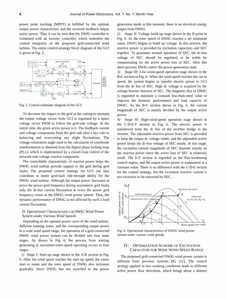
modes. The specific integrated voltage control strategy for
wide-ranged wind speed is shown in Fig. 4. The switchover
between low wind speed and high wind speed operation
modes is judged by rotor speed.
*
sdi
and *
sqi
are calculated by their own outer regulator.
Then, substituting α and β for subscripts x and y in (2) and
replacing d and q according to (5), the reference values for
α-β stationary coordinates can be expressed as
* *
*
* *
*
d q
s
d q
s
i u i ui
i u i ui
U
U
(9)
The references *
sai , *
sbi , and *
sci
are calculated through the
stationary coordinate transformation from α-β into a-b-c. The
ac-side voltage vector of SEC is regulated by switch signals
AS , BS ,
CS derived from a two-level current hysteresis
comparator. The errors between current references *
sai , *
sbi ,
*
sci
and measured currents sai ,
sbi , sci
are regarded as
inputs of the hysteresis comparator.
C. Control Strategy for Grid-connected Inverter
A double-closed-loop structure is usually applied in the
control strategy for a conventional full-power GCI such as
those in PMSM wind turbines. The given active current is
dependent on the fluctuation of dc-link voltage, which means
that the output of the outer-loop voltage regulator is regarded
as the given input of the current inner loop. However, the
GCI circuit in a DWIG wind power system is simplified so
that a boost converter is not needed since the front-end
DWIG outputs a stable high dc bus voltage with wide-ranged
wind speed. Therefore, the dc current will fluctuate with the
output power if the outer-loop voltage regulator is still
applied in a grid-connected DWIG wind turbine.
A special double-closed-loop control scheme is put forth.
The output of the outer-loop power regulator serves as the
given reference of the current inner loop, and the set value of
the power outer loop is derived from the optimal
characteristic curve of DWIG output power. The maximum
0
1*
sDCU
sDCUAS
PI
*sdi
PIsqi *
Eq. (12)
*sαi
sβi *
αβ
to
abc
*sai
*sbi
*sci
0
1
0
1
BS
CS
Voltage Vector
Amplitude
αU βU
sbcU
sai sbi sci
*
U/ fsU
sU sabU
scaUabc to αβ
flag
n
n
*
pDCU
pDCU
switch
flag
f
Fig. 4. Integrated voltage control strategy diagram of roposed
DWIG wind power system.
6 Journal of Power Electronics, Vol. ?, No. ?, Month Year
power point tracking (MPPT) is fulfilled by the optimal
output power characteristic and the received feedback output
active power. Thus it can be seen that the DWIG controller is
combined with an inverter controller, which embodies the
control integrality of the proposed grid-connected wind
turbine. The entire control-strategy block diagram of the GCI
is given in Fig. 5.
To decrease the impact to the grid at the cutting-in moment,
the output voltage vector from GCI is regulated by a space
voltage vector PWM to follow the grid-side voltage. At the
initial time, the given active power is 0. The feedback current
and voltage components from the grid side play a key role in
balancing and overcoming any slight fluctuations. The
voltage-orientation angle used in the calculation of coordinate
transformation is obtained from the digital phase locking loop
(PLL), which is implemented by a closed-loop control of the
network-side voltage reactive component.
The controllable characteristic of reactive power helps the
DWIG wind turbine provide support to the grid during grid
faults. The proposed control strategy for GCI can also
contribute to better grid-fault ride-through ability for the
DWIG wind turbine. Although the output power fluctuates at
twice the power-grid frequency during asymmetric grid faults,
only the dc-bus current fluctuation at twice the power grid
frequency exists in the DWIG wind power system. Thus, the
dynamic performance of DWIG is not affected by such a load
current fluctuation.
D. Operational Characteristics of DWIG Wind Power
System under Various Wind Speeds
Depending on the optimal power curve of the wind turbine,
different running states, and the corresponding output power
in a wide wind speed range, the operation of a grid-connected
DWIG wind power system can be divided into four main
stages. As shown in Fig. 6, the process from starting
generating to maximum-rotor-speed operating occurs in four
stages:
1) Stage I: Start-up stage shown in the A-B section in Fig.
6. After the wind speed reaches the start-up speed, the vanes
start to rotate and the rotor speed of DWIG also increases
gradually. Since DWIG has not switched to the power
generation mode at this moment, there is no electrical energy
output from DWIG.
2) Stage II: Voltage build-up stage shown in the B point in
Fig. 6. As the rotor speed of DWIG reaches a set minimum
value, DWIG begins to build up voltage. In this process, the
reactive power is provided by excitation capacitors and SEC
together. To guarantee normal operation of SEC, the dc-bus
voltage of SEC should be regulated to be stable by
compensating for the active power loss of SEC. After this
short process, DWIG enters the power-generation state.
3) Stage III: Low-wind-speed operation stage shown in the
B-C section in Fig. 6. When the wind speed reaches the cut-in
speed, the system begins to transfer electric power to GCI
from the dc bus of SEC. High dc voltage is acquired by the
voltage booster function of SEC. The magnetic flux of DWIG
is regulated to maintain a constant less-than-rated value to
improve the dynamic performance and load capacity of
DWIG. As the B-C section shows in Fig. 6, the current
magnitude of SEC is mainly decided by the output active
power.
4) Stage IV: High-wind-speed operation stage shown in
the C-D-E-F section in Fig. 6. The electric power is
transferred from the dc bus of the rectifier bridge to the
inverter. The adjustable reactive power from SEC is provided
to keep the output dc voltage stable, and the adjustable active
power keeps the dc-bus voltage of SEC steady. In this stage,
the excitation current magnitude of SEC depends mainly on
the reactive power since the active loss of SEC is relatively
small. The E-F section is regarded as the flux-weakening
control region, and the output active power is maintained at a
constant value. There is no difference with the C-D-E section
for the control strategy, but the excitation reactive current is
too excessive to be extracted by SEC.
IV. OPTIMIZATION SCHEME OF EXCITATION
CAPACITOR FOR WIDE WIND SPEED RANGE
The proposed grid-connected DWIG wind power system is
different from previous systems [8], [11]. The control
strategy applied in two working conditions leads to different
active power flow directions, which brings about a distinct
PI
*outP
*
din
+
-outP
0
P
n
di
+
-
ABC
to
dq
qi
-
+
L
L
iA
++
∫
-
θ
uq
+
-
+
-
+
+
SVPWM
1gu
udPI
PI
uq
2gu3gu4gu5gu6gu
PI+
*qu =0
uq
ud
uq
power calculation
and
ABC to dqiB iC
uA uB uC
*
PI*out
Q *
qi-outQ
+=0
outQ
Digital PLL
Fig. 5. Control schematic diagram of the GCI.
2v
3v4v
5v
1v
1n 2n
out1P
P
A
B
D
E
C
Rated output power
3n 4n
Maximum rotor speed
Rotor speed ( rev/ min)
n
Optimal power curveWind speed
P
F
1v 2v 3v 4v 5v
0n
out2
Ou
tpu
t p
ow
er c
urv
e o
f
DW
IG w
ind
tu
rbin
e
out
Fig. 6. Operational characteristics of DWIG wind power
system under various wind speeds.
Grid-Connected Dual Stator-Winding Induction Generator … 7
composition and proportion of the control- winding current.
The active current is the major component of control-winding
current under low wind speed, while the reactive component
is the primary under high wind speed. Hence the influence
generated by various excitation capacitors on the
control-winding current is also different from that of previous
systems. Therefore, the capacity optimization scheme for
SEC that is suitable for this proposed grid-connected DWIG
wind power system should be investigated.
A. Control-winding Current under Low Wind Speed
The excitation reactive current provided by SEC is merely
acting on maintaining Φm constant under low wind speed,
while the active current increases along with the active power
output. Thus, the active current occupies the leading position
in the control-winding current. To simplify our analysis, the
influence of mutual leakage between two sets of stator
windings is ignored, and only the fundamental component is
taken into consideration. The excitation reactive current fed
from SEC to adjust Φm is regarded as a current source [11].
The simplified equivalent circuit of the DWIG wind power
system with a resistance load operating under low wind speed
is shown in Fig. 7 (a), and the corresponding phasor diagram
is shown in Fig. 7 (b).
According to the Kirchhoff's circuit laws, in Fig. 7 (a), the
relationship of current phasors is expressed as
m r s pI I I I (10)
where mI is the excitation reactive current fed from SEC,
and the subscripts r ,
s , p express the equivalent rotor
winding, control winding, power winding respectively.
The amplitude of mI can be derived from the phasor
diagram,
cos sin sinm sC p L rI I I I I (11)
where sCI and
LI are the reactive component and the
active component of control-winding current. As shown in
Fig. 7 (b), all the unknown parameters in (11) can be
expressed as follows,
cosp p p
m
U I X
E
, sin L s sc s
m
I X I R
E
, sin r r
m
I X
E ,
p PI U C ,2
2 2( )
mr
rr
EI
RX
s
, mm
m
EI
X .
Thus, the reactive component of control-winding current used
to adjust the magnetic flux under low wind speed is described
as follows,
2 2
2
( )
p P pm m m rsC P
rm L s m mr
L s
m L s
U U CRE E E XI U C
RE I R X EX
s
I X
E I R
(12)
So, the magnitude of control-winding current can be
calculated by
2 2
s sC LI I I (13)
In the generation mode, the slip ratio s is negative and can
be given as follows [8], [11],
2 4 2 2 2 2
2
e
3 9 4
2
m r m r e r r
r
E R E R P R Xs
P X
(14)
Here, eP
is the electromagnetic power transferred from the
rotor to the stator. From (12)-(14), the control- winding
current under different rotor speeds and output power can be
determined.
The above derivation processes and derivation results
reveal that the amplitude and phase of the control-winding
current depend on both the excitation capacitor and output
active power (represented by LI ) under low wind speed.
Obviously, LI
plays a decisive role in the control- winding
current when operating under low wind speed.
B. Control-winding Current under High Wind Speed
Under high wind speed, the active component in sI
can
be ignored since the active power loss of the SEC is small.
This means the phase of sI
stays the same as or is the
opposite of mI if the loss is ignored. The control- winding
current can also be seen as a current source. As wind speed
increases, the reactive excitation power provided by the
excitation capacitor is excessive, and SEC extracts this part of
IsRs Lls
Ip RpLlp Llr Rr
Im
LmUp
Us
Ir
rj r
mE
Ic
C
IL Isc
Rr
1 s
s
(a) Equivalent circuit
mE
rr
R
sI
r rj XI
·
·
·
m-E·
p-U·
p pRI
p pj XI·
·
··
rI
sU
·
LI
·
sI·
pI
·
scI
·
mI
<0s
s sj XI·
s sRI·
1
(b) Phasor diagram
Fig. 7. Equivalent circuit and phasor diagram of DWIG
operating under low wind speed.
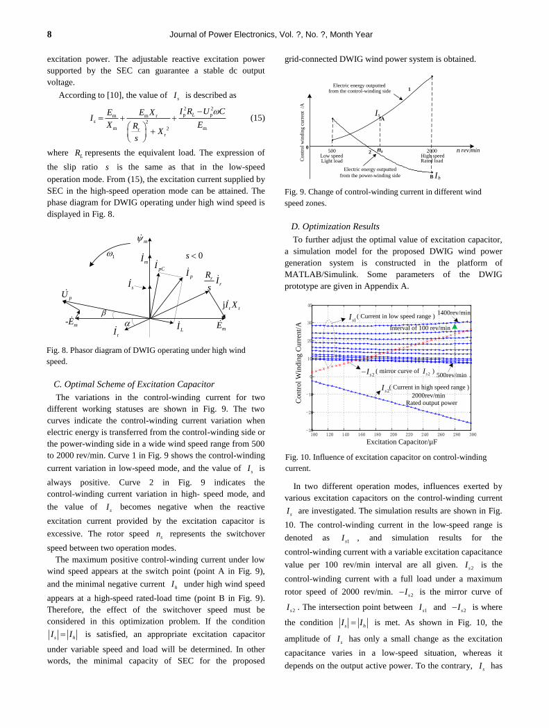
8 Journal of Power Electronics, Vol. ?, No. ?, Month Year
excitation power. The adjustable reactive excitation power
supported by the SEC can guarantee a stable dc output
voltage.
According to [10], the value of sI
is described as
2 2
p pm m r
2
m m2rr
L
s
I R U CE E XI
X ERX
s
(15)
where LR represents the equivalent load. The expression of
the slip ratio s is the same as that in the low-speed
operation mode. From (15), the excitation current supplied by
SEC in the high-speed operation mode can be attained. The
phase diagram for DWIG operating under high wind speed is
displayed in Fig. 8.
C. Optimal Scheme of Excitation Capacitor
The variations in the control-winding current for two
different working statuses are shown in Fig. 9. The two
curves indicate the control-winding current variation when
electric energy is transferred from the control-winding side or
the power-winding side in a wide wind speed range from 500
to 2000 rev/min. Curve 1 in Fig. 9 shows the control-winding
current variation in low-speed mode, and the value of sI
is
always positive. Curve 2 in Fig. 9 indicates the
control-winding current variation in high- speed mode, and
the value of sI
becomes negative when the reactive
excitation current provided by the excitation capacitor is
excessive. The rotor speed sn represents the switchover
speed between two operation modes.
The maximum positive control-winding current under low
wind speed appears at the switch point (point A in Fig. 9),
and the minimal negative current hI
under high wind speed
appears at a high-speed rated-load time (point B in Fig. 9).
Therefore, the effect of the switchover speed must be
considered in this optimization problem. If the condition
s hI I
is satisfied, an appropriate excitation capacitor
under variable speed and load will be determined. In other
words, the minimal capacity of SEC for the proposed
grid-connected DWIG wind power system is obtained.
D. Optimization Results
To further adjust the optimal value of excitation capacitor,
a simulation model for the proposed DWIG wind power
generation system is constructed in the platform of
MATLAB/Simulink. Some parameters of the DWIG
prototype are given in Appendix A.
In two different operation modes, influences exerted by
various excitation capacitors on the control-winding current
sI
are investigated. The simulation results are shown in Fig.
10. The control-winding current in the low-speed range is
denoted as 1sI , and simulation results for the
control-winding current with a variable excitation capacitance
value per 100 rev/min interval are all given. 2sI
is the
control-winding current with a full load under a maximum
rotor speed of 2000 rev/min. 2sI
is the mirror curve of
2sI . The intersection point between 1sI
and 2sI
is where
the condition s hI I is met.
As shown in Fig. 10, the
amplitude of sI
has only a small change as the excitation
capacitance varies in a low-speed situation, whereas it
depends on the output active power. To the contrary, sI has
mI
rr
RI
s
r rjI X
m
sIpI
mErI
m-E
pU
1
LI
pCI0s
Fig. 8. Phasor diagram of DWIG operating under high wind
speed.
500 2000 /rev min0
sI
hI
High speed Rated load
Electric energy outputted
1
2Low speed Light load
n
Contr
ol
win
din
g c
urr
ent
/A
ns
Electric energy outputted from the control-winding side
from the power-winding side
A
B
Fig. 9. Change of control-winding current in different wind
speed zones.
100 120 140 160 180 200 220 240 260 280 300-30
-20
-10
0
10
20
30
40
Excitation Capacitor/µF
Contr
ol
Win
din
g C
urr
ent/
A
2sI
2sI
1sI ( Current in low speed range )
2000rev/min
( Current in high speed range )
( mirror curve of )2sI
Rated output power
500rev/min
1400rev/min
Interval of 100 rev/min
Fig. 10. Influence of excitation capacitor on control-winding
current.
Grid-Connected Dual Stator-Winding Induction Generator … 9
a close relationship with the excitation capacitance value in
high-speed situations.
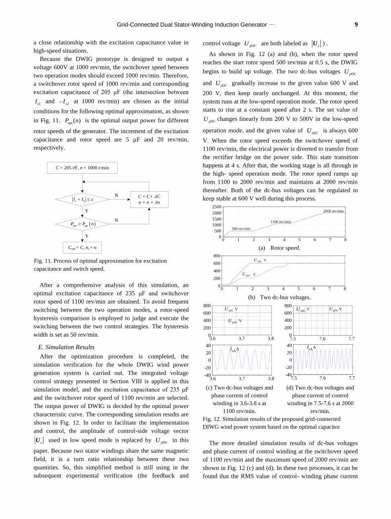
Because the DWIG prototype is designed to output a
voltage 600V at 1000 rev/min, the switchover speed between
two operation modes should exceed 1000 rev/min. Therefore,
a switchover rotor speed of 1000 rev/min and corresponding
excitation capacitance of 205 μF (the intersection between
1sI
and 2sI
at 1000 rev/min) are chosen as the initial
conditions for the following optimal approximation, as shown
in Fig. 11. ( )optP n
is the optimal output power for different
rotor speeds of the generator. The increment of the excitation
capacitance and rotor speed are 5 µF and 20 rev/min,
respectively.
After a comprehensive analysis of this simulation, an
optimal excitation capacitance of 235 μF and switchover
rotor speed of 1100 rev/min are obtained. To avoid frequent
switching between the two operation modes, a rotor-speed
hysteresis comparison is employed to judge and execute the
switching between the two control strategies. The hysteresis
width is set as 50 rev/min.
E. Simulation Results
After the optimization procedure is completed, the
simulation verification for the whole DWIG wind power
generation system is carried out. The integrated voltage
control strategy presented in Section VIII is applied in this
simulation model, and the excitation capacitance of 235 μF
and the switchover rotor speed of 1100 rev/min are selected.
The output power of DWIG is decided by the optimal power
characteristic curve. The corresponding simulation results are
shown in Fig. 12. In order to facilitate the implementation
and control, the amplitude of control-side voltage vector
sU
used in low speed mode is replaced by DCpU
in this
paper. Because two stator windings share the same magnetic
field, it is a turn ratio relationship between these two
quantities. So, this simplified method is still using in the
subsequent experimental verification (the feedback and
control voltage DCpU are both labeled as
sU ) .
As shown in Fig. 12 (a) and (b), when the rotor speed
reaches the start rotor speed 500 rev/min at 0.5 s, the DWIG
begins to build up voltage. The two dc-bus voltages DCpU
and DCsU gradually increase to the given value 600 V and
200 V, then keep nearly unchanged. At this moment, the
system runs at the low-speed operation mode. The rotor speed
starts to rise at a constant speed after 2 s. The set value of
DCpU changes linearly from 200 V to 500V in the low-speed
operation mode, and the given value of DCsU is always 600
V. When the rotor speed exceeds the switchover speed of
1100 rev/min, the electrical power is diverted to transfer from
the rectifier bridge on the power side. This state transition
happens at 4 s. After that, the working stage is all through in
the high- speed operation mode. The rotor speed ramps up
from 1100 to 2000 rev/min and maintains at 2000 rev/min
thereafter. Both of the dc-bus voltages can be regulated to
keep stable at 600 V well during this process.
0 1 2 3 4 5 6 7 80
500
1000
1500
2000
2500
500 rev/min
1100 rev/min
2000 rev/min
(a) Rotor speed.
00 11 22 33 44 55 66 77 8800
200200
400400
600600
800800
DCpU
DCsU V
V
(b) Two dc-bus voltages.
00
200200
400400
600600
800800
-40-40
-20-20
00
2020
4040
3.63.6 3.73.7 3.83.8
3.63.6 3.73.7 3.83.8
DCsU
DCpU
Asi
V
V
A
-40-40
-20-20
00
2020
4040
7.57.5 7.67.6 7.77.7
7.57.5 7.77.77.67.600
200200
400400
600600
800800DCsU DCpUV V
Asi A
(c) Two dc-bus voltages and
phase current of control
winding in 3.6-3.8 s at
1100 rev/min.
(d) Two dc-bus voltages and
phase current of control
winding in 7.5-7.6 s at 2000
rev/min.
Fig. 12. Simulation results of the proposed grid-connected
DIWG wind power system based on the optimal capacitor
The more detailed simulation results of dc-bus voltages
and phase current of control winding at the switchover speed
of 1100 rev/min and the maximum speed of 2000 rev/min are
shown in Fig. 12 (c) and (d). In these two processes, it can be
found that the RMS value of control- winding phase current
C = 205 µF, n = 1000 r/min
s hI I
out optP P n
Copt = C, ns = n
C = C+ ΔC
n = n + Δn
Y
Y
N
N
Fig. 11. Process of optimal approximation for excitation
capacitance and switch speed.
10 Journal of Power Electronics, Vol. ?, No. ?, Month Year
are both 18 A approximately. Therefore, it is obvious that the
chosen optimal capacitor can realize the capacity
minimization of SEC for the proposed grid-connected DWIG
wind power system. The correctness of simulation results will
be verified by the following experiments.
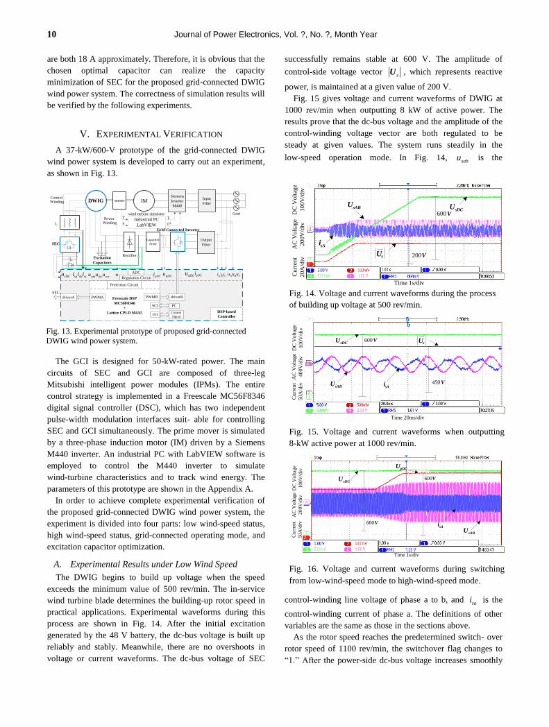
V. EXPERIMENTAL VERIFICATION
A 37-kW/600-V prototype of the grid-connected DWIG
wind power system is developed to carry out an experiment,
as shown in Fig. 13.
The GCI is designed for 50-kW-rated power. The main
circuits of SEC and GCI are composed of three-leg
Mitsubishi intelligent power modules (IPMs). The entire
control strategy is implemented in a Freescale MC56F8346
digital signal controller (DSC), which has two independent
pulse-width modulation interfaces suit- able for controlling
SEC and GCI simultaneously. The prime mover is simulated
by a three-phase induction motor (IM) driven by a Siemens
M440 inverter. An industrial PC with LabVIEW software is
employed to control the M440 inverter to simulate
wind-turbine characteristics and to track wind energy. The
parameters of this prototype are shown in the Appendix A.
In order to achieve complete experimental verification of
the proposed grid-connected DWIG wind power system, the
experiment is divided into four parts: low wind-speed status,
high wind-speed status, grid-connected operating mode, and
excitation capacitor optimization.
A. Experimental Results under Low Wind Speed
The DWIG begins to build up voltage when the speed
exceeds the minimum value of 500 rev/min. The in-service
wind turbine blade determines the building-up rotor speed in
practical applications. Experimental waveforms during this
process are shown in Fig. 14. After the initial excitation
generated by the 48 V battery, the dc-bus voltage is built up
reliably and stably. Meanwhile, there are no overshoots in
voltage or current waveforms. The dc-bus voltage of SEC
successfully remains stable at 600 V. The amplitude of
control-side voltage vector sU , which represents reactive
power, is maintained at a given value of 200 V.
Fig. 15 gives voltage and current waveforms of DWIG at
1000 rev/min when outputting 8 kW of active power. The
results prove that the dc-bus voltage and the amplitude of the
control-winding voltage vector are both regulated to be
steady at given values. The system runs steadily in the
low-speed operation mode. In Fig. 14, sabu
is the
control-winding line voltage of phase a to b, and sai
is the
control-winding current of phase a. The definitions of other
variables are the same as those in the sections above.
As the rotor speed reaches the predetermined switch- over
rotor speed of 1100 rev/min, the switchover flag changes to
“1.” After the power-side dc-bus voltage increases smoothly
Cu
rren
t
20
A/d
iv
DC
Vo
ltag
e
10
0V
/div
AC
Vo
ltag
e
20
0V
/div
Time 1s/div
sABU
sAi
sDCU600 V
200VsU
Fig. 14. Voltage and current waveforms during the process
of building up voltage at 500 rev/min.
Time 20ms/div
sDCU
sABUsAi 450 V
600VsU
Curr
ent
50
A/d
iv
DC
Volt
age
100
V/d
iv
AC
Volt
age
400
V/d
iv
Fig. 15. Voltage and current waveforms when outputting
8-kW active power at 1000 rev/min.
sDCU
pDCU
600V
sABUsAi
600V
Curr
ent
50A
/div
DC
Volt
age
100V
/div
AC
Volt
age
200
V/d
iv
Time 1s/div
Fig. 16. Voltage and current waveforms during switching
from low-wind-speed mode to high-wind-speed mode.
PowerWinding
IMDWIG sensorSiemens
Inverter
M440
Grid
Input
Filter
Industrial PC
LabVIEW
Rectifier
Output
Filter
Freescale DSP
MC56F8346
+
Lattice CPLD M4A5
PWMA
SCI PC
I/OControl
Signal
DSP-based
Controller
Grid-Connected Inverter
SEC
n
Capacitor
Array
sa sb sci i isab sbc scau u usDCu pDCu pDCi
oDCu
T
n*
T
A B Ci i i A B Cu u un pDCiADC
driverA driverBSEC
PWMB
Regulation Circuit
Pretection Circuit
L
ControlWinding
wind turbine simulator
Excitation
Capacitors
Fig. 13. Experimental prototype of proposed grid-connected
DWIG wind power system.
Grid-Connected Dual Stator-Winding Induction Generator … 11
to the given value of 600 V, the parallel diode enters into the
off-state. The electrical power is diverted to transfer from the
rectifier bridge. The dc-bus voltage of SEC is kept at the set
value of 600 V throughout the transition process without any
fluctuations, and the output dc voltage is maintained at a
stable level by controlling the reactive power of the system.
Fig. 16 shows the voltage and current waveforms of this
system during switching from low-wind-speed mode to high-
wind-speed mode.
B. Experimental Results under High Wind Speed
To avoid frequent switching between two operating
situations, the switchover speed from high-wind-speed mode
to low-wind-speed mode is defined as 1050 rev/min. Voltage
and current waveforms during switching from the
high-wind-speed mode to low-wind-speed mode are shown in
Fig. 17. During the transition process, in order to achieve a
rapid change in the two dc-bus currents, the control-winding
dc-bus voltage drops to less than 20 V.
Voltage and current waveforms operating at the maximum
rotor speed of 2000 rev/min in high-wind-speed mode are
exhibited in Fig. 18. The excess reactive power supplied by
the excitation capacitor to the generator is extracted by SEC.
The line current leads the line voltage at the phase position.
The dc-bus voltages at both winding sides are regulated to
small-scope fluctuations at the given value.
C. Experimental Results for Grid-connected Inverter
The three-phase current waveform and single-phase
voltage and current waveforms for GCI during output at 11
kW of active power are displayed in Fig. 19. It can be seen
that less harmonic content and a high power factor are
achieved. This demonstrates the accuracy of the proposed
double-closed-loop control strategy and the robustness of the
GCI without a boost converter.
D. Experimental Results for Optimization of Excitation
Capacitor
To prove the accuracy of the optimization scheme for the
excitation capacitor, some experiments are performed at
different wind speeds. The goal is to measure the
control-winding current from the start of the build-up of rotor
speed at 500 rev/min to the maximum rotor speed of 2000
rev/min (per 100 rev/min). The relationship of the output
active power and control-winding current RMS value under
different rotor speeds is shown in Fig. 20 (negative RMS
value means opposite current direction). The maximum RMS
value occurs at the switchover speed and the maximum speed.
Their corresponding voltage and current waveforms are
shown in Fig. 21 and Fig. 18, respectively.
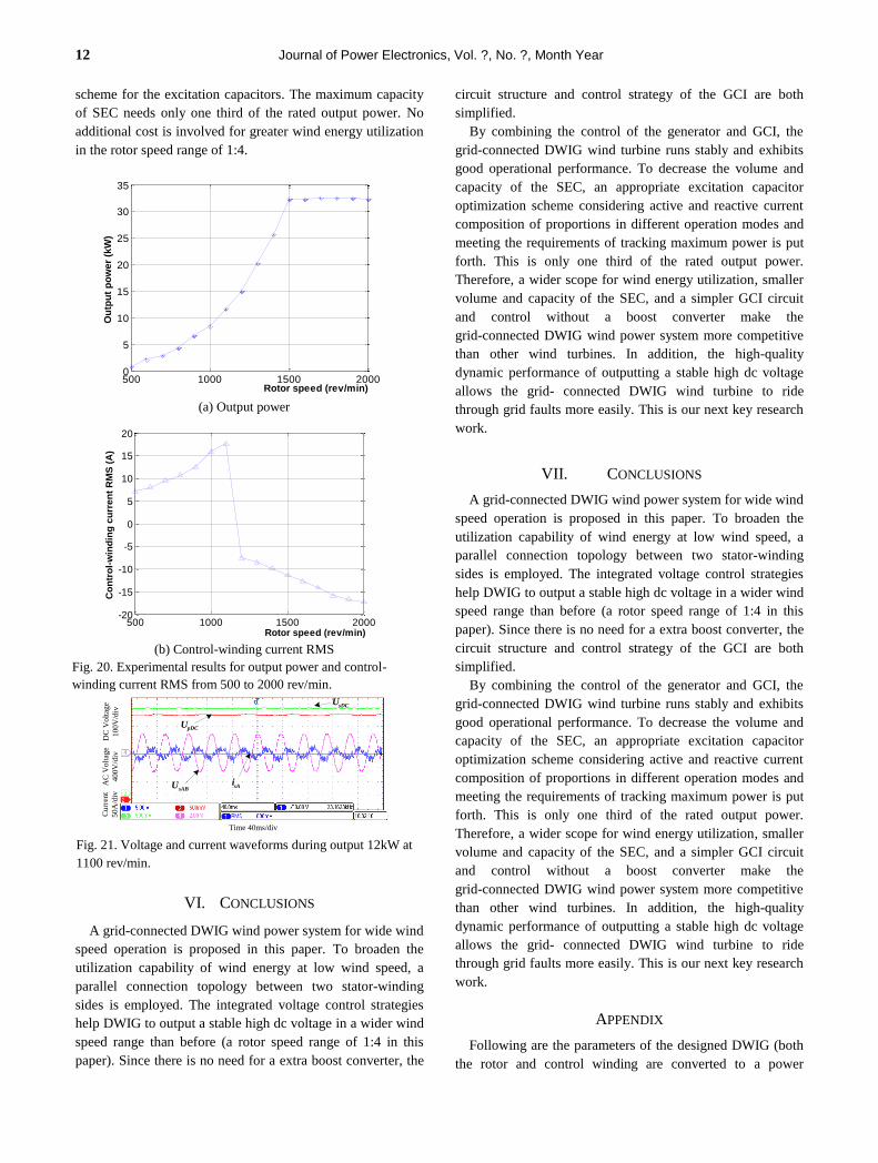
Experimental results reveal that the RMS value of the
control-winding current increases with a rise in rotor speed
during low-wind-speed mode. Once the rotor speed is higher
than the switchover speed, the control-winding current
becomes negative during the high-wind-speed mode.
Moreover, the RMS value of the control-winding current also
rises with the enhancement of rotor speed in high-wind-speed
mode. The minimal negative current almost equals the
maximum positive current, and the minimal current value is
approximately 18A. It can be seen that the results are
consistent with the theoretical analysis and simulation results.
These demonstrate the accuracy of the proposed optimization
sDCU
pDCU 600V
sABU sAi 600 V
Cu
rren
t
50
A/d
ivD
C V
olt
age
10
0V
/div
AC
Vo
ltag
e
20
0V
/div
Time 1s/div Fig. 17. Voltage and current waveforms during switching
from high-wind-speed mode to low-wind-speed mode.
sDCU pDCU
600V
sabU sai
600 V
Cu
rren
t
50
A/d
ivD
C V
olt
age
10
0V
/div
AC
Vo
ltag
e
40
0V
/div
Time 20ms/div
Fig. 18. Voltage and current waveforms during output rated 37
kW at 2000 rev/min.
A , ,B Ci i i
Cu
rren
t
25
A/d
iv
(a) Three-phase current waveforms
Ai
Ae
Time 10ms/div
AC
Volt
age
400V
/div
Cu
rren
t
25A
/div
(b) Single-phase voltage and current waveforms
Fig. 19. Voltage and current waveforms of the GCI during
output 11 kW of active power.
12 Journal of Power Electronics, Vol. ?, No. ?, Month Year
scheme for the excitation capacitors. The maximum capacity
of SEC needs only one third of the rated output power. No
additional cost is involved for greater wind energy utilization
in the rotor speed range of 1:4.
VI. CONCLUSIONS
A grid-connected DWIG wind power system for wide wind
speed operation is proposed in this paper. To broaden the
utilization capability of wind energy at low wind speed, a
parallel connection topology between two stator-winding
sides is employed. The integrated voltage control strategies
help DWIG to output a stable high dc voltage in a wider wind
speed range than before (a rotor speed range of 1:4 in this
paper). Since there is no need for a extra boost converter, the
circuit structure and control strategy of the GCI are both
simplified.
By combining the control of the generator and GCI, the
grid-connected DWIG wind turbine runs stably and exhibits
good operational performance. To decrease the volume and
capacity of the SEC, an appropriate excitation capacitor
optimization scheme considering active and reactive current
composition of proportions in different operation modes and
meeting the requirements of tracking maximum power is put
forth. This is only one third of the rated output power.
Therefore, a wider scope for wind energy utilization, smaller
volume and capacity of the SEC, and a simpler GCI circuit
and control without a boost converter make the
grid-connected DWIG wind power system more competitive
than other wind turbines. In addition, the high-quality
dynamic performance of outputting a stable high dc voltage
allows the grid- connected DWIG wind turbine to ride
through grid faults more easily. This is our next key research
work.
VII. CONCLUSIONS
A grid-connected DWIG wind power system for wide wind
speed operation is proposed in this paper. To broaden the
utilization capability of wind energy at low wind speed, a
parallel connection topology between two stator-winding
sides is employed. The integrated voltage control strategies
help DWIG to output a stable high dc voltage in a wider wind
speed range than before (a rotor speed range of 1:4 in this
paper). Since there is no need for a extra boost converter, the
circuit structure and control strategy of the GCI are both
simplified.
By combining the control of the generator and GCI, the
grid-connected DWIG wind turbine runs stably and exhibits
good operational performance. To decrease the volume and
capacity of the SEC, an appropriate excitation capacitor
optimization scheme considering active and reactive current
composition of proportions in different operation modes and
meeting the requirements of tracking maximum power is put
forth. This is only one third of the rated output power.
Therefore, a wider scope for wind energy utilization, smaller
volume and capacity of the SEC, and a simpler GCI circuit
and control without a boost converter make the
grid-connected DWIG wind power system more competitive
than other wind turbines. In addition, the high-quality
dynamic performance of outputting a stable high dc voltage
allows the grid- connected DWIG wind turbine to ride
through grid faults more easily. This is our next key research
work.
APPENDIX
Following are the parameters of the designed DWIG (both
the rotor and control winding are converted to a power
500 1000 1500 20000
5
10
15
20
25
30
35
Rotor speed (rev/min)
Ou
tpu
t p
ow
er
(kW
)
(a) Output power
500 1000 1500 2000-20
-15
-10
-5
0
5
10
15
20
Rotor speed (rev/min)
Co
ntr
ol-
win
din
g c
urr
en
t R
MS
(A
)
(b) Control-winding current RMS
Fig. 20. Experimental results for output power and control-
winding current RMS from 500 to 2000 rev/min.
sDCU
sABU sAi
Cu
rren
t
50
A/d
ivD
C V
olt
age
10
0V
/div
AC
Vo
ltag
e
40
0V
/div
Time 40ms/div
pDCU
Fig. 21. Voltage and current waveforms during output 12kW at
1100 rev/min.
Grid-Connected Dual Stator-Winding Induction Generator … 13
winding):
0.78pR ; 0.535sR ; 0.384rR ;
5.84mHlpL ; 2.86mHlrL ; 4.38mHlsL ;
165.5mHmL ; 0.57mHpsL ;
Turns ratio: : 52:60s pN N ;
Rated power: 37 kW;
Rated speed: 1500 rev/min;
The maximum speed: 2000 rev/min;
Pole pairs: 2;
Rated dc output voltage: 600 V;
Filter inductor: 3 4mH ;
Excitation capacitor: 3 235μF ;
DC bus capacitor: 1100μF / 900V ;
Voltage of battery: 48 V.
The designed parameters for the GCI are as follows:
Rated power: 50 kW;
Filter inductor: 3 4mH ;
Voltage on grid side: 155 V;
DC bus capacitor array:17mF / 900V .
ACKNOWLEDGMENT
This work was supported in part by the National Natural
Science Foundation of China under award 51407085,
Postdoctoral Science Foundation of China under award
2015M571685, the grant from the Priority Academic
Program Development of Jiangsu Higher Education
Institution and Jiangsu University Senior Talents Special
Project under award 13JDG111.
REFERENCES
[1] H. Li, and Z. Chen, “Overview of different wind generator
systems and their comparisons,” IET Renewable Power
Generation, Vol. 2, No. 2, pp. 123-138, Jun. 2008.
[2] A.C. Smith, R. Todd, M. Barnes, and P.J. Tavner,
“Improved energy conversion for doubly fed wind
generators,” IEEE Transactions on Industry Applications,
Vol. 42, No. 6, pp. 1421-1428, Nov./Dec. 2006.
[3] R.C. Bansal, T.S. Bhatti, and D.P. Kothari, “Bibliography
on the application of induction generators in non-
conventional energy systems,” IEEE Transactions on
Energy Conversion, Vol. 18, No. 3, pp. 433-439, Sep.
2003.
[4] E. Touti, R. Pusca, J. Manata, J. Brudny, and A. Chaari,
“On the use of a dimmer for a robust frequency control of
a self-excited three-phase induction wind generator,”
Journal of Power Electronics, Vol. 14, No. 3, pp.
580-591, May 2014.
[5] O. Ojo and I. E. Davidson, “A dual stator winding
induction generator with a four switch inverter-battery
scheme for control,” in Proceeding of IEEE PESC, pp.
230–234, Galway, Jun. 2000.
[6] O. Ojo and I. E. Davidson, “PWM-VSI inverter-assisted
stand-alone dual stator winding induction generator,” IEEE
Transactions on Industry Applications, Vol. 36, No. 6, pp.
1604-1611, Nov. 2000.
[7] D. Wang, W. Ma, F. Xiao, B. Zhang, D. Liu, and A. Hu,
“A novel stand-alone dual stator-winding induction
generator with static excitation regulation,” IEEE
Transactions on Industry Applications, Vol. 20, No. 4, pp.
826-835, Dec. 2005.
[8] Y. Li, Y. Hu, W. Huang, L. Liu, and Y. Zhang, “The
capacity optimization for the static excitation controller of
the dual-stator-winding induction generator operating in a
wide speed range,” IEEE Transactions on Industrial
Electronics, Vol. 56, No. 2, pp. 530-541, Feb. 2009.
[9] N.M. Kirby, L. Xu, M. Luckett, and W. Siepmann,
“HVDC transmission for large offshore wind farms,”
Power Engineering Journal, Vol. 16, No. 3, pp. 135-141,
Jul. 2002.
[10] P. Bresesti, W.L. Kling, R.L. Hendriks, and R. Vailati,
“HVDC connection of offshore wind farms to the
transmission system,” IEEE Transactions on Energy
Conversion, Vol. 22, No. 1, pp. 37-43, Mar. 2007.
[11] F. Bu, W. Huang, Y. Hu, and K. Shi, “An excitation-
capacitor-optimized dual stator-winding induction
generator with the static excitation controller for wind
energy application,” IEEE Transactions on Energy
Conversion, Vol. 26, No. 1, pp. 122-131, Mar. 2011.
[12] K. Shi, W. Huang, Y. Hu, and F. Bu, “An indirect-
field-oriented dual stator-winding induction generator for
the wind power system applications,” in Proceeding of
WNWEC, pp. 152–156, Nanjing, Sep. 2009.
[13] D. Wang, W. Ma, and Y. Guo, “Optimal design of a
self-excited capacitor in a dual-stator winding induction
generator,” IET Electric Power Applications, Vol. 3, No. 4,
pp. 334- 342, Jul. 2009.
[14] A. M. Knight and G. E. Peters, “Simple wind energy
controller for an expanded operating range,” IEEE
Transactions on Energy Conversion, Vol. 20, No. 2, pp.
459-466, Jul. 2005.
[15] E. Koutroulis, and K. Kalaitzakis, “Design of a maximum
power tracking system for wind-energy-conversion appli-
cations,” IEEE Transactions on Industrial Electronics, Vol.
53, No. 2, pp. 486-494, Apr. 2006.
[16] F. Bu, Y. Hu, W. Huang, S. Zhuang, and K. Shi, “Wide-
speed-range-operation dual stator-winding induction
generator DC generating system for wind power appli-
cations,” IEEE Transactions on Industrial Electronics ,
Vol. 30, No. 2, pp. 561-573, Mar. 2015.
[17] T. Furuhashi, S. Okuma, and Y. Uchikawa, “A study on
the theory of instantaneous reactive power,” IEEE
Transactions on Industrial Electronics, Vol. 37, No. 1, pp.
86-90, Mar. 1990.
[18] F. Z. Peng and J. Lai, “Generalized instantaneous reactive
power theory for three-phase power systems,” IEEE Trans.
On Instrumentation and Measurement, Vol. 45, No. 1, pp.
293-297, Feb. 1996.
Kai Shi was born in 1980 in Suzhou, China.
He received his B.S. in Automation and M.S.
in Power Electronic and Power Transmission
from Jiangsu University, Zhenjiang, China, in
2002 and 2005, respectively. He received the
Ph.D. in Power Electronic and Power
Transmission from Nanjing University of Aeronautics and
Astronautics, Nanjing, China, in 2012. From 2002 to today, he has

14 Journal of Power Electronics, Vol. ?, No. ?, Month Year
been always working at the School of Electrical and Information
Engineering, Jiangsu University. Since 2013, he has been an
Assistant Professor in Jiangsu University. His current research
interests include wind power generators control, grid-connected
control, and control strategies of low voltage ride through.
Peifeng Xu was born in 1980 in Nantong,
China. She received his B.S. and M.S. in
Electrical Engineering from Jiangsu
University, Zhenjiang, China, in 2002 and
2005, respectively. From 2002 to today, she
has been working at the School of Electrical
and Information Engineering, Jiangsu University, Zhenjiang,
China. Since 2007, she has been a lecturer at Jiangsu University.
Her current research interests include the design and control of
high efficiency wind power generators.
Zenqiang Wan was born in 1991 in Nantong,
China. He received his B.S. in Electrical
Engineering from Jiangsu University,
Zhenjiang, China, in 2014. Since 2014, he
has been a graduate student at the School of
Electrical and Information Engineering,
Jiangsu University, Zhenjiang, China. His current research
interests include the grid-connected control of high efficiency
wind power generators and low-voltage ride-through control.
Zhiming Fang was born in 1978 in Zhenjiang,
China. He received his M.S. degree in Control
Theory and Control Engineering from Jiangsu
University, Zhenjiang, China, in 2003. He
received his Ph.D. degree in Control Theory
and Control Engineering from Nanjing
University of Science and Technology, Nanjing, China, in 2012.
Since 2000, he has been a faculty member and he is currently a
lecturer at Jiangsu University. His main research interests include
switched systems, nonlinear control, robust control, and parallel
robot control.
Rongke Liu was born in 1977 in Changzhou,
China. He received his B.S. degree in
Mechanical Engineering from Southwest
Traffic University, Chengdu, China, in 2000.
Since 2003, he has been a senior engineer at
KTK Group, Changzhou, China. His main
research interests include the mechanical design and integrated
design of power supply systems.
Dean Zhao was born in 1956 in Changzhou,
China. He received his B.S. in Industrial
Electric Automation and M.S. in Machine
Manufacturing from Jiangsu University,
Zhenjiang, China, in 1982 and 1989,
respectively. He received Ph.D. in Power
Electronic and Power Transmission from Nanjing University of
Aeronautics and Astronautics, Nanjing, China, in 2007. Since 2000,
he has been a Professor at the School of Electrical and Information
Engineering, Jiangsu University. He is currently an Academic
Leader in Agriculture Electrification and Automation, Jiangsu
University. His current research interests include the production
process research of intelligent automation and network control, the
computer intelligent control, and robot control.


![Stator Laminated stator · · 2016-11-16Winding hotspot Average winding Lowest winding Magnet Stator back iron Housing 0 1800 3600 5400 7200 9000 20 40 60 80 100 120 140 Time [secs]]](https://img.pdfslide.us/doc/110x75/5b04e5c37f8b9a6c0b8e6eee/stator-laminated-stator-hotspot-average-winding-lowest-winding-magnet-stator-back.jpg)