Embed Size (px)
DESCRIPTION
Estimation of IQ vector components of RF field - Theory and implementation. M. Grecki , T. Jeżyński, A. Brandt. Agenda. Introduction - LLRF system Downconversion and IQ estimation VHDL implementation of IQ estimator Sources of incorrectness - PowerPoint PPT Presentation
Citation preview

Estimation of IQ vector components of RF field - Theory
and implementation
M. Grecki, T. Jeżyński, A. Brandt

Agenda
• Introduction - LLRF system
• Downconversion and IQ estimation
• VHDL implementation of IQ estimator
• Sources of incorrectness
• Simulation and optimization of IQ estimation parameters (IF, SF)
• Conclusion

Agenda
• Introduction - LLRF system
• Downconversion and IQ estimation
• VHDL implementation of IQ estimator
• Sources of incorrectness
• Simulation and optimization of IQ estimation parameters (IF, SF)
• Conclusion

FPGA
FT PZT
Klystron
AD
C
AD
CA
DC
DA
C
DA
C
DA
C
Digital feedback
~ ~ ~waveguidetunerHV
cav.1
RF power waveguide
AD
C
rf switch
~ AincAreftiming
DOOCS server
VM
E
beam
I Q
wectormodulator
Control panel
FT PZT
AD
C
AD
CA
DC
DA
C
~waveguidetuner
cav.n
AD
C
~ AincAref
....
LO - LocalOscillator
FPGA computational algorithm
[aij]
ab
ba+
Feedforwardtable
Gaintable
Setpointtable
[bij]
[zij]
...
cav A
cav B
cav Z
+
LLRF control system

Agenda
• Introduction - LLRF system
• Downconversion and IQ estimation
• VHDL implementation of IQ estimator
• Sources of incorrectness
• Simulation and optimization of IQ estimation parameters (IF, SF)
• Conclusion
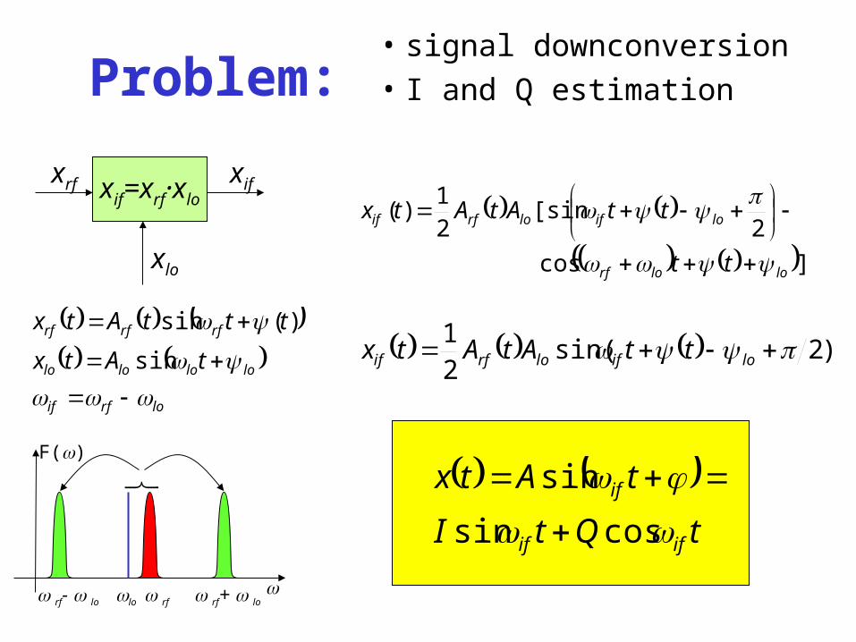
Problem:• signal downconversion
• I and Q estimation
xif=xrf·xloxrf
xlo
xif
lo
F()
rf rf- lo rf+ lo
tQtI
tAtx
ifif
if
cossin
sin
lorfif
lolololo
rfrfrf
tAtx
tttAtx
sin
)(sin
]cos
2[sin
21
)(
lolorf
loiflorfif
tt
ttAtAtx
)2sin(21 loiflorfif ttAtAtx

Sampling of downconverted signal
tQtI
tAtx
ifif
if
cossin
sin

System migration
Future:IF = 81MHz ?SF = 36MHz ?TS = 1usmany samples per TSaveraging possible (noise reduction)
Now:IF = 250kHzSF = 1MHzTS = 1us4 samples / IF signal periodprediction needed

AD Conversion parameters
• Constant SF (time uniform sampling)
• M·IF=N·SF (M,N –integer numbers)
• TS=1s, IF >= 1MHz
• SF >= 3MHz, limited by ADC parameters
• SF - averaging => noise reduction
• SF - ADC accuracy drops down
• IF - ADC accuracy drops down
Agenda
• Introduction - LLRF system
• Downconversion and IQ estimation
• VHDL implementation of IQ estimator
• Sources of incorrectness
• Simulation and optimization of IQ estimation parameters (IF, SF)
• Conclusion

IQ estimation
ixM
Q
ixM
I
SFIF
M
ii
M
ii
1
0
1
0
cos2
sin2
2
IF=81MHz, SF=36MHz
entity IQestim is port (I : buffer BREG; -- I output Q : buffer BREG; -- Q output iqr : out bit; -- IQ output ready S : in BREG; -- sample input sr : in bit; -- sample ready input clk : in bit; reset : in bit);end;
I
resetclk
sr
iqrQ
S

Numerical algorithm
sin cos
xi
18x18
14b int
14b int
24b int
>>8 >>8
>>5
32b int
*int(218/M)>>17
I Q14b int
>>5*int(218/M)
>>17
28b int
-213 < xi < 213-1
-213 < sin, cos < 213-1
%0122.0422.12113 e
The computation algorithm assures ~14bits accuracy of results

VHDL implementationDesign Summary--------------Target Device : x2v4000Target Package : ff1152Target Speed : -6Logic Utilization: Total Number Slice Registers: 64 out of 46,080 1% Number used as Flip Flops: 62 Number used as Latches: 2 Number of 4 input LUTs: 55 out of 46,080 1%Logic Distribution: Number of occupied Slices: 43 out of 23,040 1% Number of Slices containing only related logic: 43 out of 43 100% Number of Slices containing unrelated logic: 0 out of 43 0% *See NOTES below for an explanation of the effects of unrelated logicTotal Number 4 input LUTs: 80 out of 46,080 1% Number used as logic: 55 Number used as a route-thru: 25 Number of bonded IOBs: 46 out of 824 5% IOB Flip Flops: 29 Number of MULT18X18s: 4 out of 120 3% Number of GCLKs: 2 out of 16 12%
--------------Design statistics: Minimum period: 11.224ns (Maximum frequency: 89.095MHz)

Agenda
• Introduction - LLRF system
• Downconversion and IQ estimation
• VHDL implementation of IQ estimator
• Sources of incorrectness
• Simulation and optimization of IQ estimation parameters (IF, SF)
• Conclusion

Accuracy of ADC - AD6645 (1)
bitsdB 1590 bitsdB 1485

Accuracy of ADC - AD6645 (2)
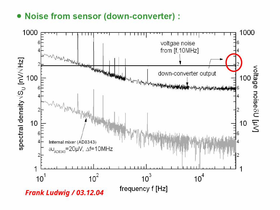
Frank Ludwig / 03.12.04

Agenda
• Introduction - LLRF system
• Downconversion and IQ estimation
• VHDL implementation of IQ estimator
• Sources of incorrectness
• Simulation and optimization of IQ estimation parameters (IF, SF)
• Conclusion

IF=81MHzSF=36MHzVn=0.5mVjit=5ps
IF=81MHzSF=72MHzVn=0.5mVjit=5ps
Aerr(mean,std,min,max)=-0.0055 / 0.0238 / -0.0977 / 0.0669 PHI(mean,std,min,max)=0.0003 / 0.0223 / -0.0845 / 0.0821 deg.
Aerr(mean,std,min,max)=-0.0024 / 0.0430 / -0.1525 / 0.1629 PHI(mean,std,min,max)=-0.0008 / 0.0263 / -0.1065 / 0.0976 deg.

IF=81MHz, Vn=0.5mV, jit=5ps
IF=9MHz, Vn=0.5mV, jit=5ps
Error vs SF

SF=36MHz, Vn=0.5mV, jit=5ps
SF=72MHz, Vn=0.5mV, jit=5ps
Error vs IF

-0.02
-0.01
0
0.01
0.02
0.03
0.04
0.05
1 10 100 1000
INL[bits]
Aerr[%]
-2.5
-2
-1.5
-1
-0.5
0
0.5
1 10 100 1000
INL[bits]
Aerr[%]
S shapeU shape
Nonlinearity of ADC
Nonlinearity does hardly influence phase
Agenda
• Introduction - LLRF system
• Downconversion and IQ estimation
• VHDL implementation of IQ estimator
• Source of incorrectness
• Simulation and optimization of IQ estimation parameters (IF, SF)
• Conclusion

Conclusion
• Algorithm of IQ calculation is straightforward • Its implementation in FPGA is simple and uses few
resources• The results of IQ calculation by Matlab script and
VHDL model is identical• the IF frequency should be chosen low (e.g. 9MHz)• the SF frequency should be chosen high, limited by
ADC SNR raise (e.g. 72MHz)• all the noise sources and jitters should be identified and
their influence on IQ estimation error investigated

Thank you for your attention.
Questions?

Some maths....
sincos QIx
when we sample x(t) we can say that we measure real part of complex RF vector in rotating coordinate system
RF
MMM QIx
QIx
QIx
sincos
......
sincos
sincos
222
111
x
from this equations I and Q have to be calculated
I
Q

Some more maths....
0
......
0
0
222
111
MMM xQbIa
xQbIa
xQbIa
0
0
2
2
iii
ii
iii
iii
iii
ii
xbbQbaI
xabaQaI
LS
22212
11211
sQaIa
sQaIa
ia
iiaa
ia
M
i
M
i
M
i
1
0
222
1
02112
1
0
211
cos
cossin
sin
ixs
ixs
M
ii
M
ii
1
02
1
01
cos
sin
where
where
that isconstantfor givenconversion scheme
that needscalculation samplesbetween
advance phase

Some math tricks...
2
cossin
0cossin
1
0
222
1
0
211
1
02112
Miaia
iiaa
M
i
M
i
M
i
Ms
Q
Ms
I
2
1
2
2
ixs
ixs
M
ii
M
ii
1
02
1
01
cos
sin
that is true if M=k*360deg
ixM
Q
ixM
I
M
ii
M
ii
1
0
1
0
cos2
sin2