Embed Size (px)
Citation preview

International Research Journal of Engineering and Technology (IRJET) e-ISSN: 2395 -0056
Volume: 03 Issue: 09 | Sep-2016 www.irjet.net p-ISSN: 2395-0072
ESTIMATION OF DEFLECTION OF A CHASIS FRAME UNDER MOVING
CONDITIONS BY USING ABAQUS SOFTWARE
Md. Abdul Fazal1, B.T. Naik 2, Doneti Gopi Krishna3, A. Sai Kumar 4 1M.Tech student, Department of Mechanical Engineering, AHTC Hyderabad
2 Associate Professor,(HOD) Department of Mechanical Engineering, AHTC, Hyderabad 3 Assistant Professor, Department of Mechanical Engineering, AHTC, Hyderabad 4Assistant Professor, Department of Mechanical Engineering, AHTC, Hyderabad
---------------------------------------------------------------------***--------------------------------------------------------------------- Abstract - A Vehicle is a Structural Assembly which consists of many components coupled together to make it run on
different initial conditions as well as under various load
conditions. Vehicles are basically designed to carry a wide
variety of loads. The chassis plays a vital role in the design of
any truck. This paper presents the estimation of deflection of
chassis for various loading cases while moving such as
Breaking, Turnings and crossing over the speed brakers is done
by using ABAQUS and also by Theoretical analysis which
include the Von-Mises stress distribution and displacement.
Finally concluded that the both analyses i.e., Theoretical and
ABAQUS results are approximately same.
Key Words: Deflection, Chassis, Abaqus, Pro – E, Hyper Mesh, structural performance, IGS file
1.1 Truck Definition And Classification
Generally, trucks are heavy motor vehicles designed for
carrying or pulling loads. Other definition of the truck is an
automotive vehicle suitable for hauling. Some other
definition are varied depending on the type of truck, such
as Dump Truck, is a truck whose contents can be emptied
without handling; the frontend of the platform can be
pneumatically raised, so that the load is discharged by
gravity. There are two classifications most applicable to
Recreational Vehicle tow trucks. The first one is the weight
classes, as defined by the US government, ranging from
Class 1 to Class 8, as listed in Table 1.1 and Table1.2. The
second is classified into a broader category: 1. Medium Light Duty Truck 2. Duty Truck 3. Heavy Duty Truck
1. INTRODUCTION
Different types of vehicles with wide variety of applications
are present in the market the capacity of which varies from
1Tonne to 40Tonnes and more. There are different types of
vehicles such as trucks, buses, cars etc. The present scenario
in automotive industry has an increase in demand of trucks
not only on the cost and weight aspects but also on improved
complete vehicle features and overall work performance. .
Vehicle chassis is an important part which supports the major
load of the vehicle assembly. As vehicle chassis plays a pivotal
role, its design has to be subjected to structural analysis to
validate against all the possible cases of load applications and
failures to strengthen the design. A chassis frame acts as a
structural backbone for a vehicle. The intrinsic function of the
truck chassis frame is to support the components and payload
placed upon it. When the truck travels along the road, the
chassis is subjected to vibration induced by road roughness
and excitation by vibrating components mounted on it.
1.2 Theories of Failures When the material starts exhibiting inelastic behavior, failure
starts to occur. Generally there are two types of material
namely Brittle and Ductile material. These ductile material
and brittle material have different failure modes depending
upon the loads. The ductile materials exhibits yielding in
elastic region and plastic deformation occurs before
material’s failure. In brittle material there is no yielding and
thus sudden failure takes place. Some of the important
theories of failures are discussed here as follows:
1. Maximum Principal stress theory (Rankine Theory)
2. Maximum Principal strain theory (StVenants Theory)
3. Maximum Strain energy (Beltrami Theory) 4. Maximum Distortion energy (Von Mises Theory) 5. Max. Shear stress theory (Tresca’s Theory)
1.2. 1 Maximum Principal Stress Theory This theory holds good for brittle materials. According to this
theory failure occurs when the maximum principal stress © 2016, IRJET | Impact Factor value: 4.45 | ISO 9001:2008 Certified Journal | Page 1239

International Research Journal of Engineering and Technology (IRJET) e-ISSN: 2395 -0056
Volume: 03 Issue: 09 | Sep-2016 www.irjet.net p-ISSN: 2395-0072
induced in a material under complex load condition
exceeds the maximum ultimate strength in a simple
tension test. So the failure condition can be expressed as,
oct
Where,
= Octahedral Shear Stress.
1 ultimate
1.2.5 Max. Shear Stress Theory
Where, 1 = Maximum Principal Stress, and
ultimate = Ultimate Stress.
1.2. 2 Maximum Principal Strain Theory According to theory it states that, “Failure occurs at a point
in a body when the maximum strain at that point exceeds
the value of the maximum strain in a uniaxial test of the
material at yield point.” The maximum normal strain in actual case is given by,
1 [
(
)]
1 E
1 2 3
Where,
1 = Maximum Principal Strain.E = Young’s Modulus
1 , 2 ,3 =Maximum Principal Stresses.And =Poisson’s Ratio.
This theory is also called Tresca’s theory. According to
theory it states that, “Yielding begins when the maximum
shear stress at a point equals the maximum shear stress at
yield in a uniaxial tension”, which is expressed as,
max
y
Where,
max = Maximum Shear Stress, and
y = Maximum Shear Stress at Yield.
Assuming 1 2 3 then, the maximum shear stress is
given by,
1
3
max 2
Also under simple tension,
y
max 2
1.2.3 Maximum Strain Energy According to theory it states that, “Failure at any point in a
body subjected to a state of stress begins only when the
energy density absorbed at that point is equal to the
energy density absorbed by the material when subjected
to elastic limit in a uniaxial stress state”. Total strain
energy (U) of deformation is given by,
U 1 [ 2 2 2 2 ( )]
2E
1 2 3 1 2 2 3 3 1
And in simple tension the strain energy is given by,
U
2
y
2E
Where, y = Yield Stress.
1.2.4 Maximum Distortion Energy: This theory is also called as Shear Energy Theory or Von
Mises-Hencky Theory. This theory states that, “Failure will
occur when distortion energy per unit volume in a part
reaches the distortion per unit volume at yield point in
tensile testing”. At the plastic limit, the elastic energy of
distortion reaches a constant value which is expressed as,
oct
2 y
3
© 2016, IRJET | Impact Factor value: 4.45 |
Hence the condition of yielding according to this theory becomes,
1 3 y
1.3 ABAQUS
Abaqus has complete solution for finite element modeling,
visualization and process Automation. By the use of
ABAQUS/CAE you can quickly and effectively create, edit,
monitor, diagnose and visualize advanced Abaqus analysis.
The spontaneous interface integrates modeling, analysis, job
management and results visualization in a consistent, easy to
use and highly productive for the experienced users.
Abaqus/CAE supports familiar interactive computer aided
engineering concepts such as feature based parametric
modeling, interactive and customization. Users can create
geometry, can import CAD models for meshing, or integrate
the solver desk that doesn’t have linked with CAD geometry. Associative interface for CATIA V5, SOLIDWORKS and
Pro/Engineer enable synchronization of CAD and CAE
assemblies and enable to spontaneous model updates
without any loss of analysis data. The open customization
toolset of ABAQUS provides a powerful process
automation solution. ISO 9001:2008 Certified Journal | Page 1240

International Research Journal of Engineering and Technology (IRJET) e-ISSN: 2395 -0056
Volume: 03 Issue: 09 | Sep-2016 www.irjet.net p-ISSN: 2395-0072
2. EXPERIMENTAL PROCEDURE AND RESULTS
The load on the chassis frame is recorded with electronic weighing machine for the following cases.
2.1 Theoretical Analysis
Equation of Beam, M
E
I y R
M = Bending Moment. I = Moment of Inertia of the section of the beam.
= Bending Stress in a fiber which is at a distance y from
neutral axis.
E = Young’s Modulus.
R = Radius of Curvature.
So from we get,
M y
and
I
Deflection of Beam is given by the equation,
3
ymax
PL P = load
3EI
1. Cross sectional area of beam (A) = 10 X 10 mm2 2. Length of beam (L) = 100 mm
3. Young’s Modulus (E) = 2x10⁵ N/mm2 Case 1: At Rest Condition. 500N Load Has Been Recorded.
Bending Moment (M) = P L = 500×100=5×10⁴N/mm2
Moment of Inertia (I) = b
4
104 833.33 mm4.
12 12
Distance y from the neutral axis = h
10 5 mm.
2 2
Substituting the values in Eq (13) we get,
= = 300 N/mm2
= =1.00 mm
Case 2: Inertia Load Or Load Due To Jerks While
Shifting Or Lifting The Chassis From One Place To
Other, 600N Load Has Been Recorded. Bending Moment(M) = P L = 600 100 6 10
4 N/mm2.
b 4 10 4
Moment of Inertia (I) = 833.33 mm4.
12 12
Distance y from the neutral axis = h
10 5 mm.
2 2
Substituting the values in Eq we get,
6 10
4 5
360 N/mm2.
833.33
Deflection of Beam is given by the equation,
= = 1.200 mm
Case 3: When Brakes Are Applied, Here 650N Load Is Has Been Recorded.
Bending Moment (M) = 4
N/mm2.
P L = 600 100 6 10
b 4 10 4
Moment of Inertia (I) =
833.33 mm4.
12 12
Distance y from the neutral axis = h
10 5 mm.
2 2
Substituting the values in Eq we get,
= = 390.00 N/mm2.
= = 1.300 mm
Case 4: When The Vehicle Goes Over A Speed Breaker Or On A Ditch, Here 750n Load Has Been Recorded. Bending Moment (M) = P L = 600 100 6 10
4 N/mm2.
b 4 10 4
Moment of Inertia (I) =
833.33 mm4.
12 12
Distance y from the neutral axis = h
10 5 mm.
2 2
Substituting the values in Eq we get,
= = 450 N/mm2
= = 1.500 mm
Case 5: Vehicle Cornering, Here 700N Load Has Been Recorded. Bending Moment (M) = P L = 600 100 6 104 N/mm2.
Moment of Inertia (I) =
b4
104
833.33 mm4. 12 12
© 2016, IRJET | Impact Factor value: 4.45 | ISO 9001:2008 Certified Journal | Page 1242
International Research Journal of Engineering and Technology (IRJET) e-ISSN: 2395 -0056
Volume: 03 Issue: 09 | Sep-2016 www.irjet.net p-ISSN: 2395-0072
Distance y from the neutral axis =
h
2
10
2
5
mm.
Substituting the values in Eq we get,
= 420 N/mm2.
= =1.400 mm
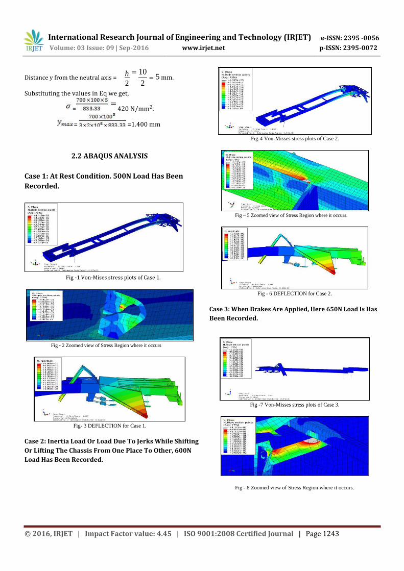
Fig-4 Von-Misses stress plots of Case 2.
2.2 ABAQUS ANALYSIS
Case 1: At Rest Condition. 500N Load Has Been Recorded.
Fig -1 Von-Mises stress plots of Case 1.
Fig – 5 Zoomed view of Stress Region where it occurs.
Fig - 6 DEFLECTION for Case 2.
Case 3: When Brakes Are Applied, Here 650N Load Is Has Been Recorded.
Fig - 2 Zoomed view of Stress Region where it occurs
Fig- 3 DEFLECTION for Case 1.
Fig -7 Von-Misses stress plots of Case 3.
Case 2: Inertia Load Or Load Due To Jerks While Shifting Or Lifting The Chassis From One Place To Other, 600N Load Has Been Recorded.
Fig - 8 Zoomed view of Stress Region where it occurs.
© 2016, IRJET | Impact Factor value: 4.45 | ISO 9001:2008 Certified Journal | Page 1243

International Research Journal of Engineering and Technology (IRJET) e-ISSN: 2395 -0056
Volume: 03 Issue: 09 | Sep-2016 www.irjet.net p-ISSN: 2395-0072
Fig – 13 Von-Misses stress plots of Case 5
Fig - 9 DEFLECTION for Case 3.
Case 4: When The Vehicle Goes Over A Speed Breaker Or .
Fig – 14 Zoomed view of Stress Region where it occurs.
On A Ditch, Here 750N Load Has Been Recorded.
Fig - 15 DEFLECTION for Case 5.
Fig - 10 Von-Misses stress plots of Case 4. Fig - 11 Zoomed view of Stress Region where it occurs
Fig - 12 DEFLECTION for Case 4
3. RESULT ANAYSIS & COMPARISION Table – 1: Comparison of Theoretical and Analytical results of stress
The above table gives the stress values which have been developed during
the load developed on the chassis frame for five cases by both theoretical and
Abaqus results. The abaqus results have been taken from the figures as shown
above. It is clearly understood that the error from the table gives evidence
that both analyses gives approximately same results. The below table gives
the deflection values for loading cases as mentioned in top by both the
analyses. From error column it is clearly understood that Abaqus software
gives approximately same values as theoretical. Case 5: Vehicle Cornering, Here 700N Load Has Been Recorded.
Table – 2 Comparisons of Theoretical and Analytical Results of Deflections
© 2016, IRJET | Impact Factor value: 4.45 | ISO 9001:2008 Certified Journal | Page 1244
International Research Journal of Engineering and Technology (IRJET) e-ISSN: 2395 -0056
Volume: 03 Issue: 09 | Sep-2016 www.irjet.net p-ISSN: 2395-0072
CONCLUSIONS The work presented herein is an attempt to study and
analyze the Heavy Vehicle Chassis Frame to get better
structural performance. From this study following
conclusions are observed, all the objectives are met and
results obtained are satisfactory. Theoretical and
analytical results are approximately same. The structure is
safe under given loading condition with the appropriate
factor of safety. Induced stresses are within the
permissible limit for all cases, thus giving a better
structural performance. The ABAQUS results from the
tables give the evidence, that the software is valid for
finding the deflection under various loading conditions.
Engineering and Technology eISSN: 2319-1163 | pISSN: 2321-7308
[8] Hemant B.Patil , Sharad D.Kachave , Eknath R.Deore
‘Stress Analysis of Automotive Chassis with Various Thicknesses’ IOSR Journal of Mechanical and Civil
Engineering (IOSR-JMCE) e-ISSN: 2278-1684 Volume 6, Issue 1 (Mar. - Apr. 2013), PP 44-49
[9] Swami K.I. , Prof. Tuljapure S.B.’ ‘Analysis of Ladder Chassis of Eicher 20.16 Using FEM’ IOSR Journal of
Applied Geology and Geophysics (IOSR-JAGG) e-ISSN:
2321–0990, p-ISSN: 2321–0982.Volume 2, Issue 1 Ver.
I. (Jan. 2014), PP 06-13
REFERENCES
[1] Hirak Patel, Panchal and Chetan, Structural Analysis of
Truck Chassis Frame and Design Optimization for
Weight Reduction, International Journal of
Engineering and Advanced Technology (IJEAT), ISSN:
2249 – 8958, Volume-2, Issue-4.
[2] Iqubal1,S.M.Oak,R.S.Kharatmal, Analytical Optimization
of Chassis Frame for 40ft D Axle Flatbed Trailer Design,
IOSR Journal of Mechanical (IOSR-JMCE), e-ISSN: 2278-1684
[3] Paul, Sarange, and Chaudhari, STRUCTURAL ANALYSIS
OFTRUCKCHASSISUSINGFINITEELEMENTMETHOD,Inte
rnationalJ.ofMultidispl.Research&Advcs.InEngg.(IJMRAE ),
ISSN 0975-7074, Vol. 4, No. I
[4] Patil, Kachave, and Deore, Stress Analysis of
Automotive Chassis with Various Thicknesses, IOSR
Journal of Mechanical and Civil Engineering (IOSR-
JMCE), e-ISSN: 2278-1684 Volume 6, Issue 1
[5] Vinayak R. Tayade*, Avinash V. Patil ‘Structural Analysis
Of Truck Chassis Using Finite Element Method’,
International Journal Of Engineering Sciences &
Research Technology. ISSN: 2277-9655 (I2OR),
Publication
[6] Kallappa Khannukar, Vinayak Kallannavar, Dr. B. S.
Manjunath ‘Dynamic Analysis Of Automotive Chassis Using Fea’ International Research Journal Of
Engineering And Technology (IRJET) E-ISSN: 2395 -
0056 Volume: 02 Issue: 09 | Dec-2015 Www.Irjet.Net
P-ISSN: 2395-0072
[7] Aditya V Sahasrabudhe , Rajesh V Patil ‘A Review On
Stress Analysis And Weight Reduction Of Automobile
Chassis’ IJRET: International Journal of Research in
© 2016, IRJET | Impact Factor value: 4.45 | ISO 9001:2008 Certified Journal | Page 1245